EP4488448A1 - Dispositif de protection contre les inondations - Google Patents
Dispositif de protection contre les inondations Download PDFInfo
- Publication number
- EP4488448A1 EP4488448A1 EP23183995.2A EP23183995A EP4488448A1 EP 4488448 A1 EP4488448 A1 EP 4488448A1 EP 23183995 A EP23183995 A EP 23183995A EP 4488448 A1 EP4488448 A1 EP 4488448A1
- Authority
- EP
- European Patent Office
- Prior art keywords
- wall element
- wall
- base
- receiving space
- protection device
- Prior art date
- Legal status (The legal status is an assumption and is not a legal conclusion. Google has not performed a legal analysis and makes no representation as to the accuracy of the status listed.)
- Pending
Links
Images


Classifications
-
- E—FIXED CONSTRUCTIONS
- E02—HYDRAULIC ENGINEERING; FOUNDATIONS; SOIL SHIFTING
- E02B—HYDRAULIC ENGINEERING
- E02B3/00—Engineering works in connection with control or use of streams, rivers, coasts, or other marine sites; Sealings or joints for engineering works in general
- E02B3/04—Structures or apparatus for, or methods of, protecting banks, coasts, or harbours
- E02B3/10—Dams; Dykes; Sluice ways or other structures for dykes, dams, or the like
- E02B3/102—Permanently installed raisable dykes
- E02B3/104—Permanently installed raisable dykes with self-activating means
Definitions
- a flood protection device can, for example, be designed as a protective wall that can protect areas near a body of water, such as a river or a lake, from flooding.
- the protective wall makes it possible, for example, to retain and/or dam flood water.
- a wall element of a flood protection device arranged in a sewer pit is known, which is provided with a float.
- the sewer pit can be flooded in order to bring the wall element into a raised position.
- the wall element sinks back into the sewer pit.
- GB 2 533 948 B describes a vertically movable wall element of a flood protection device which can be held in a raised position by means of a locking element.
- a flood protection device comprises at least one base element and one wall element, wherein the base element is designed to be introduced into the subsoil and the base element forms a receiving space for the wall element, the wall element can assume a first position in relation to the base element in which it is completely received in the receiving space and a second position in which it protrudes from the receiving space, wherein the flood protection device is designed such that the wall element can be brought from the first position into the second position by introducing a liquid, in particular water, into the receiving space.
- the wall element further has at least one groove and the base element comprises at least one pivotable flap which is designed to engage in the groove when the wall element is provided in the second position in order to hold the wall element in the second position.
- the flood protection device is designed in such a way that the introduction of the liquid, in particular water, into the receiving space displaces the wall element from the receiving space and thereby moves it into the second position.
- the receiving space is therefore also referred to as a flood chamber and the wall element as a floating body. This makes it possible, for example, to move the wall element from the first to the second position in a simple manner.
- the flood protection device can in particular be a self-activating protection device.
- the groove and the pivotable flap form a holding device which is designed to hold the wall element in the second position.
- two grooves are provided on the wall element on opposite sides of the wall element, and the base element has two pivotable flaps on opposite sides of the base element which are designed to engage in the grooves.
- the at least one flap is preferably arranged to be pivotable about an axis that extends parallel to a longitudinal direction of the base element and/or the wall element.
- the at least one groove is preferably an elongated recess that extends along the longitudinal direction of the base element and/or the wall element.
- the flap is preferably provided at the upper end of the base element. and/or the groove is provided in a region of the wall element adjacent to a lower end of the wall element, preferably in a region of the wall element corresponding to the lower third of the wall element
- the pivotable flap(s) for engaging in the groove(s) can, for example, hold the wall element in the second position even if the receiving space is no longer filled with sufficient liquid, e.g. when a flood recedes.
- the pivotable flap is preferably designed as a locking element which holds the wall element in the second position.
- the flap is designed such that a free end of the flap rests against a side wall of the wall element when the wall element is provided in the first position and/or while the wall element moves from the first to the second position.
- the pivotable flap can slide, for example, along a side wall of the wall element while the wall element moves from the first to the second position, in particular vertically upwards, and can engage with the groove in the second position of the wall element.
- the flood protection device further comprises a lifting carriage which is designed to lift the wall element in order to release the engagement of the flap with the groove, wherein the lifting carriage further preferably has a first lever arm and a second lever arm which are provided at an angle to one another, wherein the first lever arm is designed to engage with the wall element and is shorter than the second lever arm.
- the lifting carriage further preferably has a first lever arm and a second lever arm which are provided at an angle to one another, wherein the first lever arm is designed to engage with the wall element and is shorter than the second lever arm.
- the wall element has a cover plate at its upper end, which is flush with an upper end of the base element and/or rests on an upper end of the base element when the wall element is provided in the first position, and/or wherein the cover plate holds the wall element in the first position.
- the cover plate is provided in the first position in a plane of the upper end of the base element. This makes it possible, for example, to introduce the base element with the wall element in the first position into the ground at ground level.
- a lower end of the wall element in the first position of the wall element is provided at a distance from a wall of the base element delimiting the receiving space, in particular provided at a distance in the vertical direction and/or horizontal direction.
- the wall element hangs in the first position in a floating manner in the receiving space of the base element. This provides, for example, sufficient space for the liquid to be introduced into the receiving space.
- the lifting carriage is designed to engage an underside of the cover plate and/or the wall element has a recess at its upper end which is designed to engage with the lifting carriage.
- a force applied by the lifting carriage to the wall element in order to lift the wall element upwards can thus be applied to the wall element or the cover plate in a simple manner, for example.
- the base element is made of concrete and/or is essentially U-shaped.
- the base element is preferably a prefabricated element. This can be used to provide, for example, a receiving space that is protected from the environment (the ground) and at the same time is accessible from above.
- the wall element is designed as a floating body and/or made of aluminum, plastic or foam.
- the wall element is designed to be substantially flat, with a surface of the wall element serving in particular to hold back flood water.
- the surface of the wall element is provided in a plane that extends along a direction of movement of the wall element from the first to the second position and/or vice versa.
- the wall element can, for example, be part of a protective wall, or a protective wall can be formed by several Basic elements with respective wall elements are arranged adjacent to each other in the subsurface.
- the wall element has a widening section at its lower end
- the receiving space of the base element has a tapering section at its upper end
- the widening section of the wall element and the tapering section of the receiving space abut one another in the second position of the wall element and/or are designed to limit a movement of the wall element in relation to the base element and/or to hold the wall element in the second position, wherein more preferably the at least one groove is provided on the widening section of the wall element.
- the base element has at least one inlet for introducing the liquid into the receiving space and/or at least one outlet for discharging the liquid from the receiving space, wherein the at least one inlet is further preferably connectable to a hydrant and/or the at least one outlet is preferably connectable to the sewer system and/or wherein the at least one outlet is preferably designed to be closable.
- an inlet for example a water inlet opening
- an outlet for example in the form of a water outlet
- the flood protection device comprises a plurality of base elements arranged next to one another with respective wall elements, wherein the base elements are provided next to one another without any connection so that liquid, in particular water, can penetrate into the receiving spaces of the base elements through a gap provided between adjacent base elements, and/or wherein the base elements are arranged next to one another in such a way that the majority of the wall elements form a protective wall in the second position of the wall elements.
- the base elements are preferably arranged next to one another without seals. This makes it possible, for example, to provide a flood protection device made up of individual elements in a modular manner, which can simplify installation of the same, for example, and/or whereby, for example, a dimension and/or shape of the flood protection device can be made variable.
- An inventive use of a flood protection device described above for protection against flooding comprises at least one step of introducing a liquid, in particular water, into the receiving space of the at least one base element in order to bring the wall element into the second position, wherein the liquid is preferably supplied from a hydrant and/or wherein flood water penetrates into the receiving space.
- the use of the flood protection device further comprises a step of introducing at least one base element, preferably a plurality of base elements, into the subsoil, so that the at least one base element is provided with its upper end on a surface of the subsoil and/or so that an upper end of the at least one wall element is provided on a surface of the subsoil.
- the base element is preferably introduced into the subsoil at ground level. This makes it possible, for example, to
- the at least one wall element provided in the second position is provided with a covering device, in particular in the form of a waterproof Tarpaulin, wherein the covering direction further preferably additionally covers an area of the subsoil on a side of the at least one wall element which faces the flood water.
- a covering device in particular in the form of a waterproof Tarpaulin, wherein the covering direction further preferably additionally covers an area of the subsoil on a side of the at least one wall element which faces the flood water.
- the use of the flood protection device further comprises a step of discharging the liquid from the at least one receiving space, in particular through an outlet provided on the receiving space which is connected to the sewerage system, in order to bring the wall element from the second to the first position.
- the use of the flood protection device further comprises a step of lifting the wall element provided in the second position by means of a lifting truck and releasing the engagement of the flap with the groove, wherein the lifting truck further preferably has a first lever arm and a second lever arm which are provided at an angle to one another, wherein the first lever arm is brought into engagement with the wall element and the first lever arm is shorter than the second lever arm.
- the second lever arm can be operated manually in order to lift the wall element with the least possible effort.
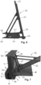
- the flood protection device 1 comprises at least one base element 2 and one wall element 3.
- the base element 2 has a receiving space 4 for receiving the wall element 3 therein, which is also referred to as a flood chamber.
- the base element 2 is essentially U-shaped. It extends from an upper end 2a to a lower end 2b over a height H.
- the receiving space 4 of the base element 2 is formed between the legs of the U-shaped base element 2. It is open towards the upper end 2a of the base element 2 and extends from the upper end 2a in the direction of the lower end 2b to a base 5 of the receiving space 4 over a height H1 which is smaller than the total height H of the base element 2.
- a width B1 of the base element 2 perpendicular to the height H is formed by the two legs of the U-shape of the base element. Perpendicular to the width B1 and the height H, the base element 2 extends over a length L1.
- the base element preferably has a substantially constant cross-section of the U-shape along the length L1.
- the height H of the base element 2 can be, for example, 1.6 meters, the width B1, for example, 0.6 or 0.7 meters, and the length L1, for example, 1 to 2 meters.
- the base element is made of concrete.
- the receiving space 4 of the base element 2 has a tapered section 6 at the upper end 2a of the base element.
- the wall of the base element 2 delimiting the receiving space 4 is formed obliquely in a section adjacent to the upper end 2a, so that the receiving space 2 is formed in a narrowing or wedge-shaped manner in the direction of the width B1 (width direction) of the base element 2 towards its upper end 2a.
- the tapered section 6 is preferably formed over the entire length L1 of the base element 2. It can, for example, extend over a quarter of the height H1 of the receiving space 4.
- the base element 2 has two anchoring rails or step sections 8 at its upper end 2a, which are provided on opposite sides of the receiving space 4 in the width direction.
- Each step section 8 preferably extends over the entire length L1 of the base element 2.
- the step sections 8 can also be formed only in sections along the length L1 of the base element 2.
- the step sections each form a recess in an upper side at the upper end 2a of the base element 2.
- Each step section 8 has at least one locking strip or flap 9, which is mounted on the step section 8 so as to be pivotable about an axis A.
- the axis A runs parallel to the longitudinal direction of the base element.
- the free ends 9a of the flaps 9 protrude into the receiving space 4.
- the flaps 9 can each be formed over the entire length L1 of the base element 2, or only in sections along the length L1.
- the flaps 9 are designed to engage in a groove formed in a wall of the wall element 3 (see below) when the wall element is provided in the second position (see Fig. 5 ). In the first position of the wall element, the flaps rest with their free ends 9a on the side walls 10 of the wall element (not shown in the figures).
- the flaps 9 can also be attached to the clamping element 7 (see Fig. 8 - Fig. 12 ).
- the base element 2 has at least one inlet for introducing a liquid, in particular water, into the receiving space 4, e.g. in the form of a water inlet opening (not shown in the figures).
- the inlet can be connected to a water supply, for example a hydrant, in a water-conducting manner, so that the receiving space 4 can be flooded with water from the water supply.
- the base element 2 has at least one outlet for discharging the liquid, in particular water, from the receiving space 4, e.g. in the form of a water outlet (not shown in the figures).
- the outlet can be connected to the sewer system in a water-conducting manner in order to drain the water from the receiving space 4 into the sewer system.
- the outlet is preferably designed to be closable, e.g. by means of a slide that selectively closes or opens the outlet (not shown in the figures).
- the wall element 3 also referred to as floating element, is designed to be accommodated in the receiving space 4 of the base element 2.
- the wall element 3 extends as in Fig. 3 shown, from an upper end 3a to a lower end 3b over a height H2 which is smaller than the height H1 of the receiving space 4 (see Fig. 1 , 4 ).
- the side walls 10 of the wall element extending from the upper end 3a to the lower end 3b form surfaces which serve to retain flood water when the wall element is provided in the second position (see Fig. 5 ). Between the two side walls 10, the wall element 3 extends over a width B2 which is smaller than or equal to the width of the receiving space 4 of the base element 2 in the width direction of the base element 2 (see Fig. 4 ).
- the wall element 3 has a driveable cover plate 11. In the width direction, the cover plate 11 protrudes beyond the side walls 10 of the wall element 3.
- the cover plate 11 is designed to be mounted on the upper end 2a of the base element 2 (see. Fig. 4 ) or to support oneself on it when the wall element 3 is in the first position (see Fig. 1 ).
- one or more recesses 17 can be provided at the upper end 3a of the wall element, in particular below the cover plate, which are designed to engage with a lifting carriage 20 described below (see Fig. 6 ) is/are trained.
- the cover plate 11 has downwardly extending projections 12 at its ends delimiting the cover plate 11 in the width direction, as shown in Fig. 2 shown.
- the projections 12 are designed to engage in recesses 13 which are formed at the upper end 2a of the base element 2 (see Fig. 2 ). This means that in the first position of the wall element (see Fig. 1 ) a movement of the wall element 3 in the width direction can be prevented.
- the wall element 3 has a widening section 14 which is complementary to the tapering section 6 of the base element 2 (see Fig. 4 ).
- the sections of the side walls 10 which are adjacent to the lower end 3b in the height direction are slanted or wedge-shaped, so that the width B2 of the wall element 3 increases towards the lower end 3b.
- the widening section 14 of the wall element 3 is designed such that it is located in the region of the tapering section 6 of the receiving space 4 on the wall of the wall element 2 which delimits the receiving space 4 (see Fig. 4 ) when the wall element 3 is in the second position (see Fig. 5 ).
- the widening section 14 is preferably formed over the entire length L2 of the wall element 3. It can, for example, extend over a quarter to a sixth of the height H2 of the wall element 3.
- the wall element 3 has a recess or groove 15 formed in each of the side walls 10.
- the groove 15 extends along the longitudinal direction of the wall element 3 and is preferably formed over the entire length L2.
- the groove 15 can also be formed only in sections along the length L2, but preferably in the areas of the length L2 in which the flap(s) 9 of the base element 2 (see Fig. 4 ) is/are formed.
- the groove 15 is formed in a region of the widening section 14.
- the groove 15 is formed to be connected to the flap 9 of the base element 2 (see Fig. 4 ) to be engaged when the wall element 3 is in the second position (see Fig. 5 ).
- the wall element 3 can assume a first position in relation to the base element 2 and a second position different from the first position.
- the first and second positions of the wall element 3 are spaced apart from one another in the height direction of the base element 2, ie the wall element can be moved away from the base element 2 by a movement in the vertical direction (along the height H of the base element). first to the second position and vice versa, as described below.
- the first position of the wall element 3 is in Fig. 1 shown.
- Fig. 1 are the groove 15 of the wall element and the flap 9 of the base element (see Fig. 3, 4 ) not shown.
- the wall element 3 rests with its cover plate 11 on the top or upper end 2a of the base element 2, so that the upper end 3a of the wall element 3, or the top of the cover plate 11, and the upper end 2a of the base element 2 are arranged essentially in one plane.
- the cover plate 11 can rest on the step sections 8 formed on the base element 2.
- the wall element 3 is completely accommodated in the receiving space 4 of the base element 2, with the exception of the cover plate 11.
- the lower end 3b of the wall element 3 is spaced from the base 5 of the receiving space 4 in the height direction, and in the width direction the side walls 10 of the wall element 3 are spaced from a wall of the base element 2 delimiting the receiving space 4, as in Fig. 1 shown.
- the wall element 3 In the first position, the wall element 3 thus hangs floating in the receiving space 4 of the base element 2 and is held in this position by the cover plate 11.
- the flap 9 formed on the base element 2 is provided in a lowered position in which it rests against the step section 8 and/or protrudes into the receiving space 4, and does not protrude in the vertical direction beyond the upper end 2a of the wall element 2 (in Fig. 1 not shown).
- the free ends 9a of the flap 9 can, for example, rest against the side walls 10 of the wall element 10 (not shown in the figures).
- the receiving space 4 of the base element 2 is not sealed against the wall element, in particular its cover plate 11.
- a liquid in particular water, can penetrate into the receiving space from the top through a gap formed between the cover plate 11 and the upper end 2a and/or the step section 8 of the base element 2 (not shown in the figures).
- FIG. 5 The second position of the wall element 3 in relation to the base element 2 is shown schematically.
- the wall element 3 is opposite the first position (see Fig. 1 ) in the height direction with respect to the base element 2 and protrudes upwards from the receiving space 4.
- the upper end 3a of the wall element 3, or the cover plate 11, is thus spaced apart in the height direction (vertically) from the upper end 2a of the base element 2.
- the side walls 10 protrude upwards from the base element 2.
- the widening section 14 of the wall element 3 rests against the tapering section 6 of the receiving space 4 of the base element 2 and is preferably wedged with the tapering section 6 so that further movement of the wall element 3 relative to the base element 2 upwards is prevented.
- the widening section 14 and the tapering section 6 thus form a limit or a stop for the movement of the wall element 3 with respect to the base element 2 in the vertical direction (height direction) upwards.
- the wall element 2 is held in the second position by wedging the widening section 14 in the tapering section 6, or the wedging can increase the stability of the wall element 3 with respect to forces acting in the width direction, e.g. caused by flood water.
- the flap 9 of the base element 2 engages or folds into the groove 15 of the wall element 3 so that the free end 9a of the flap 9 is received in the groove. This holds the wall element 3 in the second position.
- the at least one flap 9 and the groove 15 together form a holding device which holds the wall element 3 in the second position or prevents the wall element 3 from returning to the first position.
- At least one basic element 2 is placed in the subsoil, e.g. in the ground along a lake shore or a river.
- an excavation can be made along a line on which the flood protection device is to be built.
- the excavation can, for example, be approximately 1.6 meters deep and 0.6 to 0.7 meters wide.
- the excavation is dimensioned such that the at least one basic element 2 is embedded in the subsoil
- the at least one base element 2 is introduced into the subsoil in such a way that it is provided at ground level, ie so that the upper end 2a of the base element 2 is provided in a plane of the surface 16 of the subsoil (ground), as in Fig. 7 shown.
- a plurality of base elements 2 are introduced into the subsurface so that they are adjacent to one another in the longitudinal direction.
- the base elements 2 are provided next to one another without any connection, so that a liquid, in particular water, can penetrate into the receiving spaces 4 of the base elements 2 through a gap provided between adjacent base elements 2 (not shown in the figures).
- the plurality of base elements 2 are arranged such that the side walls 10 of the wall elements 3 together form a protective wall or a protective dam in the second position of the wall elements in order to hold back and/or dam flood water.
- the wall elements 3 In order to move the wall elements 3 from the first to the second position, it is only necessary to flood the receiving space with a liquid. No additional, e.g. mechanical and/or electronic, drive devices are required to move the wall elements.
- the at least one wall element, or the protective wall formed from a plurality of wall elements is covered with a covering device, e.g. a waterproof tarpaulin (not shown in the figures).
- a covering device e.g. a waterproof tarpaulin (not shown in the figures).
- the covering device is additionally attached to an area of the subsoil on the side of the at least one wall element which faces the flood water, i.e. on the water side. This can, for example, prevent flood water from penetrating the subsoil and undermining the flood protection device.
- the wall elements By engaging the flap 9 of the base elements 2 in the groove 15 of the wall elements 3 (see Fig. 3 to 5 ), the wall elements are held in the second position, even if the liquid is drained from the receiving space, e.g. when the flood water recedes.
- the flaps 9 and grooves 15 thus prevent the wall elements 2 from moving back from the second to the first position.
- the present invention is not limited to the embodiment described above. Rather, modifications to the flood protection device are possible.
- the individual elements such as the base element and/or the wall element, can deviate from the shape and/or size described above.
- the holding device is formed by the at least one flap of the base element, which engages in the at least one groove of the wall element.
- another holding device can also be provided, which is designed to hold the wall element in the second position and/or to prevent the wall element from returning to the first position.
Landscapes
- Engineering & Computer Science (AREA)
- General Engineering & Computer Science (AREA)
- Environmental & Geological Engineering (AREA)
- Ocean & Marine Engineering (AREA)
- Mechanical Engineering (AREA)
- Civil Engineering (AREA)
- Structural Engineering (AREA)
- Buildings Adapted To Withstand Abnormal External Influences (AREA)
- Barrages (AREA)
Priority Applications (2)
| Application Number | Priority Date | Filing Date | Title |
|---|---|---|---|
| EP23183995.2A EP4488448A1 (fr) | 2023-07-06 | 2023-07-06 | Dispositif de protection contre les inondations |
| EP24183102.3A EP4488449A1 (fr) | 2023-07-06 | 2024-06-19 | Dispositif de protection contre les inondations |
Applications Claiming Priority (1)
| Application Number | Priority Date | Filing Date | Title |
|---|---|---|---|
| EP23183995.2A EP4488448A1 (fr) | 2023-07-06 | 2023-07-06 | Dispositif de protection contre les inondations |
Publications (1)
| Publication Number | Publication Date |
|---|---|
| EP4488448A1 true EP4488448A1 (fr) | 2025-01-08 |
Family
ID=87158114
Family Applications (2)
| Application Number | Title | Priority Date | Filing Date |
|---|---|---|---|
| EP23183995.2A Pending EP4488448A1 (fr) | 2023-07-06 | 2023-07-06 | Dispositif de protection contre les inondations |
| EP24183102.3A Pending EP4488449A1 (fr) | 2023-07-06 | 2024-06-19 | Dispositif de protection contre les inondations |
Family Applications After (1)
| Application Number | Title | Priority Date | Filing Date |
|---|---|---|---|
| EP24183102.3A Pending EP4488449A1 (fr) | 2023-07-06 | 2024-06-19 | Dispositif de protection contre les inondations |
Country Status (1)
| Country | Link |
|---|---|
| EP (2) | EP4488448A1 (fr) |
Citations (7)
| Publication number | Priority date | Publication date | Assignee | Title |
|---|---|---|---|---|
| DE4437098A1 (de) | 1994-05-28 | 1995-11-30 | Gega Josef | Hochwasserschutzwand |
| GB2369387A (en) | 2000-08-10 | 2002-05-29 | Ivan Philipov | Buoyant automatic flood barrier |
| DE10302744A1 (de) * | 2003-01-24 | 2004-07-29 | Reh, Karl-Heinz, Dipl.-Ing. | Hochwasserschutzwand |
| WO2009076199A2 (fr) * | 2007-12-05 | 2009-06-18 | Linares Miguel A | Système de digue avec des composants déplaçables et d'actionnement de niveau d'eau |
| US20160244927A1 (en) * | 2015-02-12 | 2016-08-25 | Rsa Protective Technologies, Llc | Method and system for a rising floodwall system |
| GB2533948B (en) | 2015-01-08 | 2019-06-12 | Fluds Ltd | Flood defence apparatus and method |
| WO2021259919A1 (fr) * | 2020-06-22 | 2021-12-30 | Floodsolutions Nv | Barrière anti-inondation à fermeture automatique |
Family Cites Families (4)
| Publication number | Priority date | Publication date | Assignee | Title |
|---|---|---|---|---|
| NL9201601A (nl) * | 1992-09-16 | 1994-04-18 | Andreas Schmidt Apol | Beschermingsinrichting tegen hoog water. |
| NL1017109C2 (nl) * | 2000-03-18 | 2001-09-21 | Cornelis Elizabeth Rijlaarsdam | Waterkering. |
| DE10162568A1 (de) * | 2001-12-19 | 2003-07-17 | Seidl & Partner Gmbh Gesamtpla | Bauwerksegment für ein Hochwasserschutzbauwerk, Bauwerk und Verfahren zur Errichtung des Bauwerks |
| US9453315B2 (en) * | 2014-02-11 | 2016-09-27 | Scott Roy | Hydrostatic fluid containment system |
-
2023
- 2023-07-06 EP EP23183995.2A patent/EP4488448A1/fr active Pending
-
2024
- 2024-06-19 EP EP24183102.3A patent/EP4488449A1/fr active Pending
Patent Citations (8)
| Publication number | Priority date | Publication date | Assignee | Title |
|---|---|---|---|---|
| DE4437098A1 (de) | 1994-05-28 | 1995-11-30 | Gega Josef | Hochwasserschutzwand |
| GB2369387A (en) | 2000-08-10 | 2002-05-29 | Ivan Philipov | Buoyant automatic flood barrier |
| DE10302744A1 (de) * | 2003-01-24 | 2004-07-29 | Reh, Karl-Heinz, Dipl.-Ing. | Hochwasserschutzwand |
| WO2009076199A2 (fr) * | 2007-12-05 | 2009-06-18 | Linares Miguel A | Système de digue avec des composants déplaçables et d'actionnement de niveau d'eau |
| US7972081B2 (en) | 2007-12-05 | 2011-07-05 | Oria Collapsibles, Llc | Sea wall system with displaceable and water level actuating components |
| GB2533948B (en) | 2015-01-08 | 2019-06-12 | Fluds Ltd | Flood defence apparatus and method |
| US20160244927A1 (en) * | 2015-02-12 | 2016-08-25 | Rsa Protective Technologies, Llc | Method and system for a rising floodwall system |
| WO2021259919A1 (fr) * | 2020-06-22 | 2021-12-30 | Floodsolutions Nv | Barrière anti-inondation à fermeture automatique |
Also Published As
| Publication number | Publication date |
|---|---|
| EP4488449A1 (fr) | 2025-01-08 |
Similar Documents
| Publication | Publication Date | Title |
|---|---|---|
| DE69628299T2 (de) | Uferhochwasserschutzwand | |
| DE3122401A1 (de) | Befestigungsvorrichtung fuer ein pfahlfoermiges element | |
| EP0802285A2 (fr) | Système de protection contre les crues | |
| EP0684342A2 (fr) | Barrage pour la protection contre les crues | |
| DE2838431C2 (de) | Klapptor zum Sperren von Flüssen, Kanälen, Docks u.ä | |
| DE102011111127B4 (de) | Hochwasser-Schutzsystem | |
| EP4488448A1 (fr) | Dispositif de protection contre les inondations | |
| DE202018102880U1 (de) | Schott für den Hochwasserschutz und Durchgang mit einem solchen Schott | |
| EP1428948A1 (fr) | Caniveau d'écoulement | |
| DE3117954A1 (de) | Verfahren zum aufbau einer stuetzwandanordnung | |
| DE29617121U1 (de) | Entwässerungsrinne für den Einbau vor Tür- oder Fensterelementen | |
| DE10037454B4 (de) | Neuartige Bauweise von Stauzisternen in Bergregionen | |
| DE102004033962B4 (de) | Versenkbare Flutwasserschutzanlage | |
| DE19827092C1 (de) | Deich bzw. Deichkonstruktion sowie Verfahren zur Herstellung und Verfahren zum Betrieb desselben | |
| DE202019104122U1 (de) | Baugrubenumschließung zum Schutz der Umgebung einer im Watt befindlichen Baugrube vor Verunreinigungen aus dieser Baugrube | |
| DE102014108274B4 (de) | Hochwasser-Schutzsystem | |
| AT513567A1 (de) | Gerinne zur Abfuhr von Oberflächenwässern | |
| DE4437098A1 (de) | Hochwasserschutzwand | |
| EP1731682A2 (fr) | Système de canalisation à cascade pour eaux de surface | |
| DE102004015322B4 (de) | Hochwasserbarriere | |
| WO2004044334A1 (fr) | Systeme de protection contre les hautes eaux | |
| DE10023750C1 (de) | Vorrichtung zum Verhindern des Wasseraustritts aus Kanalöffnungen bei Hochwasser | |
| AT526639B1 (de) | Schutzsystem | |
| DE4344703A1 (de) | Erdbauwerk | |
| DE102005048303A1 (de) | Hochwasser-Schutzsystem |
Legal Events
| Date | Code | Title | Description |
|---|---|---|---|
| PUAI | Public reference made under article 153(3) epc to a published international application that has entered the european phase |
Free format text: ORIGINAL CODE: 0009012 |
|
| STAA | Information on the status of an ep patent application or granted ep patent |
Free format text: STATUS: THE APPLICATION HAS BEEN PUBLISHED |
|
| AK | Designated contracting states |
Kind code of ref document: A1 Designated state(s): AL AT BE BG CH CY CZ DE DK EE ES FI FR GB GR HR HU IE IS IT LI LT LU LV MC ME MK MT NL NO PL PT RO RS SE SI SK SM TR |
|
| STAA | Information on the status of an ep patent application or granted ep patent |
Free format text: STATUS: REQUEST FOR EXAMINATION WAS MADE |
|
| 17P | Request for examination filed |
Effective date: 20250703 |