EP4491460A1 - Aktuatorpufferstruktur, rückspiegel und fahrzeug - Google Patents
Aktuatorpufferstruktur, rückspiegel und fahrzeug Download PDFInfo
- Publication number
- EP4491460A1 EP4491460A1 EP23188778.7A EP23188778A EP4491460A1 EP 4491460 A1 EP4491460 A1 EP 4491460A1 EP 23188778 A EP23188778 A EP 23188778A EP 4491460 A1 EP4491460 A1 EP 4491460A1
- Authority
- EP
- European Patent Office
- Prior art keywords
- base frame
- actuator
- buffer block
- output shaft
- block
- Prior art date
- Legal status (The legal status is an assumption and is not a legal conclusion. Google has not performed a legal analysis and makes no representation as to the accuracy of the status listed.)
- Granted
Links
Images


Classifications
-
- B—PERFORMING OPERATIONS; TRANSPORTING
- B60—VEHICLES IN GENERAL
- B60R—VEHICLES, VEHICLE FITTINGS, OR VEHICLE PARTS, NOT OTHERWISE PROVIDED FOR
- B60R1/00—Optical viewing arrangements; Real-time viewing arrangements for drivers or passengers using optical image capturing systems, e.g. cameras or video systems specially adapted for use in or on vehicles
- B60R1/02—Rear-view mirror arrangements
- B60R1/06—Rear-view mirror arrangements mounted on vehicle exterior
- B60R1/062—Rear-view mirror arrangements mounted on vehicle exterior with remote control for adjusting position
- B60R1/064—Rear-view mirror arrangements mounted on vehicle exterior with remote control for adjusting position by manually powered actuators
-
- B—PERFORMING OPERATIONS; TRANSPORTING
- B60—VEHICLES IN GENERAL
- B60R—VEHICLES, VEHICLE FITTINGS, OR VEHICLE PARTS, NOT OTHERWISE PROVIDED FOR
- B60R1/00—Optical viewing arrangements; Real-time viewing arrangements for drivers or passengers using optical image capturing systems, e.g. cameras or video systems specially adapted for use in or on vehicles
- B60R1/02—Rear-view mirror arrangements
- B60R1/06—Rear-view mirror arrangements mounted on vehicle exterior
- B60R1/076—Rear-view mirror arrangements mounted on vehicle exterior yieldable to excessive external force and provided with an indexed use position
-
- B—PERFORMING OPERATIONS; TRANSPORTING
- B60—VEHICLES IN GENERAL
- B60R—VEHICLES, VEHICLE FITTINGS, OR VEHICLE PARTS, NOT OTHERWISE PROVIDED FOR
- B60R1/00—Optical viewing arrangements; Real-time viewing arrangements for drivers or passengers using optical image capturing systems, e.g. cameras or video systems specially adapted for use in or on vehicles
- B60R1/02—Rear-view mirror arrangements
- B60R1/06—Rear-view mirror arrangements mounted on vehicle exterior
- B60R1/062—Rear-view mirror arrangements mounted on vehicle exterior with remote control for adjusting position
- B60R1/07—Rear-view mirror arrangements mounted on vehicle exterior with remote control for adjusting position by electrically powered actuators
- B60R1/072—Rear-view mirror arrangements mounted on vehicle exterior with remote control for adjusting position by electrically powered actuators for adjusting the mirror relative to its housing
-
- B—PERFORMING OPERATIONS; TRANSPORTING
- B60—VEHICLES IN GENERAL
- B60R—VEHICLES, VEHICLE FITTINGS, OR VEHICLE PARTS, NOT OTHERWISE PROVIDED FOR
- B60R1/00—Optical viewing arrangements; Real-time viewing arrangements for drivers or passengers using optical image capturing systems, e.g. cameras or video systems specially adapted for use in or on vehicles
- B60R1/02—Rear-view mirror arrangements
- B60R1/06—Rear-view mirror arrangements mounted on vehicle exterior
- B60R1/062—Rear-view mirror arrangements mounted on vehicle exterior with remote control for adjusting position
- B60R1/07—Rear-view mirror arrangements mounted on vehicle exterior with remote control for adjusting position by electrically powered actuators
Definitions
- the present disclosure relates to the field of automotive technology, specifically to an actuator buffer structure, a rear-view device, and a motor vehicle.
- a rear-view device presents different rear-views when different drivers drive the vehicle.
- the mirror surface needs to be adjusted to meet the needs of the different drivers.
- the way to adjust the mirror surface is divided into electric and manual adjustment in the prior art.
- the folding durability of rear-view devices via electric adjustment is relatively good.
- the gear is easily damaged in the manual adjustment process, so enhancing the folding durability of manual adjustment is an important factor to improve the quality of the rear-view devices.
- One objective of the present disclosure is to provide a actuator buffer structure that can prevent damage to the actuator during manual adjustment.
- Another objective of the present disclosure is to provide a rear-view device with good product quality.
- Another objective of the present disclosure is to provide a vehicle with good product quality.
- an actuator buffer structure comprising a base frame for installing a rear-view element;an actuator fixedly installed and rotatably connected to the base frame; and a clutch assembly, wherein the output shaft of the actuator is connected to the base frame through the clutch assembly, wherein the actuator is suitable for driving the output shaft to rotate the base frame together with the rear-view element around the axis through the clutch assembly, wherein the base frame is capable of disengaging from the output shaft through the clutch assembly under external force, so that the base frame rotates together with the rear-view element relative to the output shaft via the actuator.
- the output shaft is able to drive the base frame together with the rear-view element to rotate around the axis via the clutch assembly.
- the output shaft is disengaged from the base frame via the clutch assembly and remains stationary with the actuator.
- the clutch assembly includes an adjusting buffer block and a spring; wherein the adjusting buffer block is axially slidably installed on the output shaft through a guiding structure, and the adjusting buffer block is adapted to be elastomically connected to the actuator or the base frame through the spring.
- the adjusting buffer block may be linked with the base frame through the clutch assembly; and, when the actuator is started, the adjusting buffer block maintains engagement with the base frame in the circumferential direction through the clutch assembly under the action of elasticity; whereas, when the base frame is driven by external force, the adjusting buffer block disengages from the engagement with the base frame in the circumferential direction via the clutch assembly.
- the adjusting buffer block is slidably matched with the output shaft through a through-hole.
- the guiding structure may include a guide groove that is axially extended along the output shaft on the side, and a guiding block that is set on the side wall of the through-hole; wherein the guiding block is slidably matched with the guide groove along the axis and simultaneously limitedly matched with it along the circumferential direction.
- the adjusting buffer block forms part of the clutch assembly by frictional engagement with the base frame in the circumferential direction through the end face.
- the driving force of the actuator is less than the frictional force between the end face of the adjusting buffer block and the base frame in the circumferential direction.
- the pressing force received by the base frame is greater than the frictional force but less than the self-locking force of the output shaft.
- the clutch assembly comprises a clutch groove set on the end face of the adjusting buffer block and a clutch block set on the base frame; wherein the clutch groove and the clutch block engage with each other along the circumferential direction via an inclined plane; such that, when the actuator is started, the driving force of the actuator is less than the engaging force of the clutch groove and the clutch block along the circumferential direction; and, when the base frame is driven by external force, the pressing force on the base frame is greater than the engaging force but less than the self-locking force of the output shaft.
- the clutch assembly further comprises a base frame buffer block, which can be detachably installed on the base frame.
- the base frame buffer block is adapted to axially slide with the adjusting buffer block via a connecting hole disposed at the center thereof, and by beingmatched with the positioning sleeve.
- the clutch block is disposed on the end face of the base frame buffer block, forming the clutch assembly between the adjusting buffer block and the base frame buffer block.
- the base frame includes a first installation area and a second installation area that are interconnected.
- the actuator is installed in the first installation area and the output shaft extends to the second installation area.
- the clutch assembly is installed in the second installation area, and the base frame buffer block is matched with the second installation area by means of a positioning structure.
- the clutch assembly is first installed on the output shaft, and then the actuator, together with the clutch assembly, is installed on the base frame.
- the base frame buffer block is connected to the side wall of the second installation area through fasteners at the center.
- the positioning structure includes at least one horizontal limiting surface set on the side of the base frame buffer block and at least one horizontal positioning surface set on the side of the second installation area.
- the base frame buffer block is adapted to fit against the positioning surface through the limiting surface.
- the end of the second installation area is provided with an installation sleeve penetrating the base frame, and the axis of the output shaft is aligned with the axis of the installation sleeve; wherein the actuator is first installed on the base frame, and then the clutch assembly is installed along the installation sleeve on the output shaft, and the base frame buffer block is fixed on the exterior of the installation sleeve by a pair of symmetrically arranged fasteners; the positioning structure includes a pair of positioning columns spaced apart and set on the outer end sides of the installation sleeve, and a pair of positioning hole spaced apart and set on the side of the base frame buffer block; and the base frame buffer block is adapted to be positioned and matched with the positioning columns via the positioning hole.
- a rear-view device of the present disclosure comprises the above actuator buffer structure.
- a vehicle of the present disclosure comprises the above rear-view device.
- the present disclosure has the beneficial effects below: By connecting the output shaft of the actuator to the base frame via the clutch assembly, damage to the actuator caused by relative rotation between the output shaft of the actuator and the actuator can be avoided by separating the clutch assembly during manual adjustment of the rear-view element angle; thereby effectively improving the service life of the actuator.
- orientations or positional relationships indicated by the terms “center”, “transverse”, “longitudinal”, “length” “width”, “thickness”, “upper”, “lower”, “front”, “rear”, “left”, “right”, “vertical”, “horizontal”, “top”, “bottom”, “inside” or “interior”, “outside” or “exterior”, “clockwise”, “anticlockwise”, and the like are orientations or positional relationships as shown in the drawings, and are only for the purpose of facilitating and simplifying the description of the present disclosure instead of indicating or implying that devices or elements indicated must have particular orientations, and be constructed and operated in the particular orientations, so that these terms cannot construed as limiting the specific protection scope of the present disclosure.
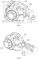
- One aspect of the present disclosure provides an actuator buffer structure, as shown in FIG. 1 to FIG. 14 .
- One preferred embodiment includes a base frame 100 for installing a rear-view element and an actuator 200 fixedly positioned and rotatably coupled to the base frame 100.
- the actuator 200 can drive the base frame 100 via an output shaft 220 to rotate the rear-view element about the axis of the output shaft 220 to achieve angular adjustment of the rear-view element.
- the actuator 200 When the user adjusts the angle of the rear-view element electrically, the actuator 200 is started. At this time, the clutch assembly 3 can maintain engagement, so that the actuator 200 can drive the rear-view element to deflect in a similar way as traditional methods, that is, the output shaft 220 of the actuator 200 is connected to the base frame 100 in the circumferential direction through the clutch assembly 3. Thus, after the actuator 200 is started, it can drive the base frame 100 together with the rear-view element to rotate by driving the rotation of the output shaft 220.
- the actuator 200 When the user manually adjusts the angle of the rear-view element, the actuator 200 is in a stopped state, and at this time, the base frame 100 can separate the clutch assembly 3 under manual drive to separate the actuator 200 together with the output shaft 220, which is self-locking, from the base frame 100 and keep them stationary. Then, the base frame 100 can drive the rear-view element to rotate around the axis of the output shaft 220 under manual drive.
- the actuator 200 and the output shaft 220 Compared to the traditional manual adjustment methods, during the rotation of the rear-view element, the actuator 200 and the output shaft 220 always remain relatively stationary, that is, there is no relative rotation between the two, thereby avoiding damage to the actuator 200 caused by the relative rotation of the output shaft 220 with respect to the actuator 200, and effectively improving the service life of the actuator 200.
- one side of the actuator 200 is provided with an installation section 210, and the actuator 200 can be installed on the body of a motor vehicle (not shown) through the installation section 210.
- the axial extension direction of the installation section 210 is perpendicular to the axis of the output shaft 220; when the base frame 100 rotates in cooperation with the actuator 200, the axis of rotation of the base frame 100 can coincide with the axis of the output shaft 220.
- the rear-view element can be provided in form of a mirror and/or camera.
- the actuator 200 In the traditional methods of adjusting the angle of the rear-view element via the actuator 200, it is necessary to rotate the base frame 100 and the actuator 200 during installation, and fix the output shaft 220 of the actuator 200 to the base frame 100. Then, when the actuator 200 drives the output shaft 220 to rotate, the output shaft 220 can drive the base frame 100 and the installed rear-view element to rotate together. Since the stability of the rear-view element needs to be ensured during use, generally, after the actuator 200 stops, the actuator 200 can grip the output shaft 220 via a brake structure, to keep the base frame 100 stable with the help of the brake of the output shaft 220.
- the driving force exerted on the base frame 100 by the output shaft 220 of the actuator 200 will forcibly disengage the brake and rotate around the actuator 200. This can easily cause damage to the brake structure of the actuator 200, and may cause the actuator 200 to malfunction and fail to maintain stability. And therefore reduce its folding durability.
- the clutch assembly 3 is installed between the output shaft 220 of the actuator 200 and the base frame 100.
- the clutch assembly 3 When electrically adjusting the angle of the rear-view element, the clutch assembly 3 is in the engaged state, that is, the output shaft 220 of the actuator 200 and the base frame 100 are stably connected through the clutch assembly 3, so that the actuator 200 can stably drive the output shaft 220 to rotate the rear-view element.
- the clutch assembly 3 can separate the output shaft 220 and the base frame 100, so that the actuator 200 and the output shaft 220 form a whole through the self-locking structure of the holding brake.
- the actuator 200 and the output shaft 220 remain stationary, so that the base frame 100 can drive the rear-view element to rotate around the axis of the output shaft 220 together with the base frame 100, whereas in contrast, traditionally a relative rotation between the actuator 200 and the output shaft 220 is avoided.
- the clutch assembly 3 comprises an adjusting buffer block 32 and a spring 31.
- the adjusting buffer block 32 can be axially slidably installed on the output shaft 220 through a guiding structure. That is, the adjusting buffer block 32 can only move axially relative to the output shaft 220 under the guidance of the guiding structure.
- the adjusting buffer block 32 can be matched with the base frame 100 through the clutch assembly.
- the adjusting buffer block 32 can also be elastically connected to the actuator 200 or the base frame 100 through the spring 31, and the spring 31 can apply the necessary engagement force to the clutch assembly through spring force.
- the adjusting buffer block 32 when adjusting the rear-view element electrically, the adjusting buffer block 32 can be kept engaged with the base frame 100 under the action of the spring force of the spring 31 through the clutch assembly, and then the output shaft 220 can drive the base frame 100 to rotate synchronously under the engagement force of the clutch assembly, so that the base frame 100 drives the rear-view element to deflect around the axis of the output shaft 220 to achieve angle adjustment.
- the pressure applied manually will be greater than the engagement force applied to the clutch assembly by the spring 31, causing the clutch assembly to disengage and separate, and then the adjusting buffer block 32 can remain stationary through the clutch assembly, while the base frame 100 rotates relative to the adjusting buffer block 32.
- the output shaft 220 will also remain stationary with the adjusting buffer block 32, that is, the actuator 200, the output shaft 220 and the adjusting buffer block 32 will remain stationary synchronously, to ensure that there is no relative motion between the actuator 200 and the output shaft 220, thereby avoiding damage to the actuator 200 and the output shaft 220 due to relative rotation.
- the spring 31 can apply a biting force to the clutch assembly by being opposed to the actuator 200 and the adjusting buffer block 32 at both ends, thus using the elastic force generated by the compression of the spring 31.
- the adjusting buffer block 32 can also be matched by being opposed to the base frame 100 through the spring 31 near the end close to the actuator 200, or the adjusting buffer block 32 can also be matched by being opposed to the base frame 100 through the spring 31 away from the end far from the actuator 200, and thereby applying a engagement force to the clutch assembly through the elastic force generated by the compression or stretching of the spring 31.
- the adjusting buffer block 32 slides and fits with the output shaft 220 through a connecting hole 320.
- the guiding structure includes a guide groove 221 extending axially along the side of the output shaft 220, and a guide block 3220 set on the side wall of the connecting hole 320.
- the guide block 3220 slides and fits with the guide groove 221 axially, and is also limitedly fitted along the circumferential direction.
- the guide groove 221 can also be set on the side of the connecting hole 320, and the guide block 3220 is correspondingly set on the side of the output shaft 220.
- the guide groove 221 is preferably set on the side of the output shaft 220, and the guide block 3220 is set on the side of the connecting hole 320.
- Structure 1 As shown in FIG. 3 to FIG. 6 , a plane is machined along the axis on the side of the output shaft 220 by processes such as cutting and grinding, and the plane can form the required guide groove 221 relative to the output shaft 220. At the same time, while machining the connecting hole 320, a plane extending along the axis can be left on the side of the connecting hole 320, and the plane can form the required guiding block 3220 relative to the connecting hole 320.
- the adjusting buffer block 32 when installing the adjusting buffer block 32, the adjusting buffer block 32 can be inserted over the output shaft 220 through the connecting hole 320, and then the side plane of the output shaft 220 can match with the side plane of the connecting hole 320 to make the adjusting buffer block 32 only axially movable relative to the output shaft 220.
- the planes forming the guide groove 221 and the guide block 3220 can be horizontal planes, arc-shaped planes, or other shaped planes, as long as the adjusting buffer block 32 and the output shaft 220 cannot rotate relative to each other in the circumferential direction.
- Structure 2 The guide groove 221 can be a spline groove set on the side of the output shaft 220, and the guiding block 3220 can be a spline set on the inner side of the connecting hole 320.
- the adjusting buffer block 32 can be spline-connected to the output shaft 220.
- the end face of the adjusting buffer block 32 is flat, and the adjusting buffer block 32 can form part of the clutch assembly with by engagement of the base frame 100 through frictional force with the end face.
- the adjusting buffer block 32 can be pressed against the inner wall of the base frame 100 in the axial direction opposite to the end face under the spring force of the spring 31.
- the spring force of the spring 31 acting on the adjusting buffer block 32 can be converted into positive pressure between the end face of the adjusting buffer block 32 and the base frame 100.
- the adjusting buffer block 32 is engaged with the inner wall of the base frame 100 in the circumferential direction through the frictional force formed by the positive pressure.
- the driving force of the actuator 200 needs to be smaller than the frictional force between the end face of the adjusting buffer block 32 and the inner wall of the base frame 100 along the circumferential direction, to ensure that the output shaft 220 and the base frame 100 are in frictional engagement for synchronous movement.
- the actuator 200 can drive the rear-view element to rotate with the rotation of the output shaft 220 to achieve angle adjustment.
- the pressing force manually applied to the base frame 100 needs to be greater than the frictional force between the end face of the adjusting buffer block 32 and the inner wall of the base frame 100 along the circumferential direction, and the pressing force applied to the base frame 100 also needs to be smaller than the self-locking force between the output shaft 220 and the actuator 200, to ensure that the base frame 100 can drive the rear-view element to rotate while the output shaft 220 can remain relatively stationary with the actuator 200.
- a positioning sleeve 333 is also set on the side wall of the base frame 100 where the adjusting buffer block 32 is set.
- the adjusting buffer block 32 can be positioned and matched with the positioning sleeve 333 through the connecting hole 320 in the middle to ensure the structural stability when the adjusting buffer block 32 is friction matched with the base frame 100.
- the clutch assembly 3 further includes a base frame buffer block 33.
- the base frame buffer block 33 can be detachably installed at the corresponding position of the base frame 100 through fasteners.
- the positioning sleeve 333 is located in the middle of the end face of the adjusting buffer block 32 directly opposite the base frame buffer block 33.
- the base frame buffer block 33 can be supported and matched with the adjusting buffer block 32 through the positioning sleeve 333;
- the adjusting buffer block 32 can achieve a friction match between the end face and the end face of base frame buffer block 33, thereby forming the required clutch assembly.
- the friction performance may not necessarily meet the needs of the clutch assembly. Therefore, by installing the additional base frame buffer block 33 for friction match with the adjusting buffer block 32, and setting the performance of the base frame buffer block 33, it can be ensured that the match between the base frame buffer block 33 and the adjusting buffer block 32 meets the needs of the clutch assembly.
- the clutch assembly includes a clutch groove 321 set on the end face of the adjusting buffer block 32 and a clutch block 331 set on the base frame 100.
- the adjusting buffer block 32 can be axially engaged with the end face of the clutch block 331 through the end face of the clutch groove 321 under the spring force of the spring 31, so that the clutch groove 321 and the clutch block 331 can be engaged along the circumferential direction through the inclined surface under the action of the spring force.
- the driving force of the actuator 200 needs to be less than the engagement force of the clutch groove 321 and the clutch block 331 along the circumferential direction, so as to ensure that the output shaft 220 and the base frame 100 maintain synchronous movement through the engagement of the clutch groove 321 and the clutch block 331, such that the actuator 200 can drive the rear-view element to rotate with the output shaft 220 to achieve angle adjustment.
- the pressing force applied to the base frame 100 needs to be greater than the engagement force of the clutch groove 321 and the clutch block 331, and at the same time, the pressing force applied to the base frame 100 needs to be less than the self-locking force of the output shaft 220 and the actuator 200.
- the positions of the clutch groove 321 and the clutch block 331 can be interchanged, that is, the clutch groove 321 is set on the base frame 100 and the clutch block 331 is set on the adjusting buffer block 32.
- the clutch groove 321 is set on the adjusting buffer block 32 and the clutch block 331 on the base frame 100. But other postions are possible.
- the specific shape of the clutch groove 321 and the clutch block 331 is not specifically limited as long as the stable engagement between the clutch groove 321 and the clutch block 331 can be achieved through an inclined surface in the circumferential direction.
- the inclined surface of the clutch groove 321 and the clutch block 331 in the circumferential direction can be an arc surface, a flat surface, or other shaped surface, as long as the above requirements of the clutch assembly are met.
- the specific number of settings for the clutch groove 321 and the clutch block 331 can be selected by those skilled in the art according to actual needs. It can be one corresponding unit or multiple corresponding units.
- the base frame 100 is provided with a side wall of the clutch block 331 and a positioning sleeve 333.
- the clutch block 331 is located on the side of the positioning sleeve 333.
- the adjusting buffer block 32 can be positioned and matched with the positioning sleeve 333 through the connecting hole 320, ensuring the stability of the mating structure of the clutch groove 321 and the clutch block 331.
- the adjusting buffer block 32 is generally first fitted to the output shaft 220, and then installed together with the actuator 200 within the base frame 100. Therefore, it is generally inconvenient to provide a positioning structure for the adjusting buffer block 32 at the corresponding position of the base frame 100, which leads to the unstable structure of the adjusting buffer block 32 when it is cooperated with the clutch block 331 on the base frame 100 through the clutch groove 321, which in turn can easily affect the normal use of the clutch assembly.
- the adjusting buffer block 32 can be supported while effectively reducing or avoiding the jumping of the adjusting buffer block 32 when it rotates in the circumferential direction.
- the adjusting buffer block 32 is not provided with a clutch groove 321, but an extension 322 is set on the end face of the adjusting buffer block 32.
- the connecting hole 320 of the adjusting buffer block 32 passes through the extension 322, and the guide block 3220 is set on the side wall of the corresponding connecting hole 320 of the extension 322. Therefore, when the adjusting buffer block 32 is matched with the positioning sleeve 333 through the connecting hole 320, it can avoid interference between the guide block 3220 and the positioning sleeve 333.
- the clutch block 331 and the base frame 100 are integrally formed.
- the preferred setting method for the clutch block 331 is to use the above setting method two.
- the clutch assembly 3 further comprises the base frame buffer block 33.
- the base frame buffer block 33 can be detachably installed at the corresponding position of the base frame 100 by fasteners.
- the positioning sleeve 333 is arranged in the middle of one end face of the base frame buffer block 33, and the clutch block 331 is located on the side of the same end face of the positioning sleeve 333.
- the base frame buffer block 33 can be supported and matched with the adjusting buffer block 32 through the positioning sleeve 333, and under the action of the spring 31, the adjusting buffer block 32 can be engaged with the base frame buffer block 33 that is provided with the clutch block 331 by setting an end face with a clutch groove 321, thus forming the required clutch assembly.
- One embodiment of the present disclosure includes the base frame 100 with interconnected first installation area 110 and second installation area 120.
- the actuator 200 is installed in the first installation area 110 and its output shaft 220 extends to the second installation area 120.
- the clutch assembly 3 is installed in the second installation area 120, and the base frame buffer block 33 can be matched with the second installation area 120 through a positioning structure.
- the actuator 200 can form an actuator buffer assembly through assembly with the base frame 100 via the clutch assembly 3.
- the actuator buffer assembly mainly includes the following two installation methods.
- Installation method 1 The base frame 100 is aranged at the end of the second installation area 120 away from the first installation area 11.;
- the installation process of clutch assembly 3 on the base frame 100 is as follows: first, install the clutch assembly 3 on the output shaft 220 of the actuator 200, and then install the actuator 200 together with the clutch assembly 3 in the corresponding first installation area 110 and the second installation area 120 of the base frame 100.
- the middle of the base frame buffer block 33 is provided with a second installation hole 330, and the side wall in the middle of the second installation area 120 of the base frame 100 away from the first installation area 110 is provided with a first installation hole 124.
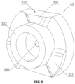
- the positioning structure includes at least one horizontal limiting surface 332 set on the side of the base frame buffer block 33, and at least one horizontal positioning surface set on the side of the second installation area 120.
- the base frame buffer block 33 can be fitted with the positioning surface through the limiting surface 332 to ensure the structural stability of base frame buffer block 33.
- connection accuracy of the fasteners is generally low, so the fasteners only need to ensure the connection between the base frame buffer block 33 and the base frame 100 in the axial direction.
- the positioning accuracy of the base frame buffer block 33 can be effectively improved by the fitting of the positioning surface and the limit surface 332 in the circumferential direction, which can further improve the structural stability of the clutch assembly 3 during operation.
- the specific number of limiting surfaces 332 and positioning surfaces can be selected by those skilled in the art according to actual needs. For example, as shown in FIG. 6 and FIG. 9 , the number of limiting surfaces 332 and positioning surface are both two, and the two limiting surfaces 332 and two positioning surfaces are symmetrically arranged.
- the base frame buffer block 33 is a disc-shaped structure. Symmetrical horizontal planes parallel to the axis can be processed on the side of the base frame buffer block 33 through processing such as washing and grinding, and the two horizontal planes are the limiting surfaces 332.
- the positioning block 121 can be formed on both side walls symmetrically in the second installation area 120. Both end faces of the positioning block 121 are horizontal surfaces, forming the required positioning surface.
- Installation method 2 Install the installation sleeve 122 in the second installation area 120 of the base frame 100 away from the end of the first installation area 110, and the installation sleeve 122 is connected to the second installation area 120.
- the installation process of the clutch assembly 3 on the base frame 100 is as follows: First, install the actuator 200 on the base frame 100, and then install the clutch assembly 3 along the installation sleeve 122 on the output shaft 220.
- the actuator 200 when assembling the actuator 200, the actuator 200 can be rotatably installed in the first installation area 110, and the output shaft 220 of the actuator 200 can extend to the second installation area 120, and the axis of the output shaft 220 is aligned with the axis of the installation sleeve 122.
- a pair of symmetric second installation holes 330 are arranged on the outer side of the base frame buffer block 33, and a pair of first installation holes 124 are symmetrically arranged on the outer side of the installation sleeve 122.
- the spring 31 can be first fitted onto the output shaft 220 of the actuator 200 along the opening of the installation sleeve 122.
- the adjusting buffer block 32 is also slidably installed along the opening of the installation sleeve 122 onto the output shaft 220, and the guide groove 221 is aligned and matched with the guide block 3220.
- the base frame buffer block 33 is inserted into the connecting hole 320 of the adjusting buffer block 32 by means of the positioning sleeve 333, and the second installation hole 330 of the base frame buffer block 33 is aligned with the first installation hole 124 of the installation sleeve 122, and then a pair of fasteners are respectively passed through the corresponding second installation hole 330 and the first installation hole 124 for fastening connection.
- the base frame buffer block 33 is generally a disc structure.
- a cover plate 334 can be set on the end face of the base frame buffer block 33 where no clutch block 331 is set.
- the size of the cover plate 334 is larger than the opening size of the installation sleeve 122, so the second installation hole 330 can be set on the side of the cover plate 334 to ensure that the cover plate 334 can be secured to the installation sleeve 122 by fasteners in the axial direction, thereby ensuring the axial stability of the base frame buffer block 33.
- the positioning structure includes a pair of positioning columns 123, which are spaced apart from the outer side of the installation sleeve 122, and a pair of positioning holes 3340, which are spaced apart from the side of the base frame buffer block 33. Therefore, the base frame buffer block 33 can be positioned and coordinated with the positioning column 123 through the positioning hole 3340, ensuring the stability of the structural circle of the base frame buffer block 33.
- a preferred embodiment includes an actuator 200 and a base frame 100, and the actuator 200 and the base frame 100 can be matched with the actuator buffer structure described above.
- Another aspect of the present disclosure provides a vehicle, wherein a preferred embodiment comprises the above rear-view device .
Landscapes
- Engineering & Computer Science (AREA)
- Multimedia (AREA)
- Mechanical Engineering (AREA)
- Rear-View Mirror Devices That Are Mounted On The Exterior Of The Vehicle (AREA)
- Mechanical Operated Clutches (AREA)
- Vibration Prevention Devices (AREA)
Applications Claiming Priority (1)
| Application Number | Priority Date | Filing Date | Title |
|---|---|---|---|
| CN202310843211.0A CN116552383B (zh) | 2023-07-10 | 2023-07-10 | 一种执行器缓冲结构、后视镜及车辆 |
Publications (2)
| Publication Number | Publication Date |
|---|---|
| EP4491460A1 true EP4491460A1 (de) | 2025-01-15 |
| EP4491460B1 EP4491460B1 (de) | 2025-11-12 |
Family
ID=87503970
Family Applications (1)
| Application Number | Title | Priority Date | Filing Date |
|---|---|---|---|
| EP23188778.7A Active EP4491460B1 (de) | 2023-07-10 | 2023-07-31 | Aktuatorpufferstruktur, rückspiegel und fahrzeug |
Country Status (3)
| Country | Link |
|---|---|
| US (1) | US20250018863A1 (de) |
| EP (1) | EP4491460B1 (de) |
| CN (1) | CN116552383B (de) |
Citations (6)
| Publication number | Priority date | Publication date | Assignee | Title |
|---|---|---|---|---|
| DE112017001911T5 (de) * | 2016-04-08 | 2018-12-20 | Kabushiki Kaisha Tokai-Rika-Denki-Seisakusho | Betrachtungsvorrichtung für ein Fahrzeug |
| DE102019122123B3 (de) * | 2019-08-16 | 2020-10-29 | Motherson Innovations Company Limited | Aktuator, Unterbaugruppe mit Aktuator und Spiegelkopf, Rückblickvorrichtung, Tür und Fahrzeug |
| US20210086694A1 (en) * | 2019-09-20 | 2021-03-25 | Honda Motor Co., Ltd. | Vehicle door mirror assembly |
| US20220176878A1 (en) * | 2012-01-24 | 2022-06-09 | Motherson Innovations Company Limited | Rear View Device With Actuator And Gasket Sealing Head Mover |
| CN217705650U (zh) * | 2022-05-17 | 2022-11-01 | 浙江极氪智能科技有限公司 | 一种外后视镜组件及具有其的车辆 |
| WO2023006761A1 (en) * | 2021-07-30 | 2023-02-02 | Motherson Innovations Company Ltd. | Method for moving at least one rearview device and actuator |
Family Cites Families (11)
| Publication number | Priority date | Publication date | Assignee | Title |
|---|---|---|---|---|
| JP3617163B2 (ja) * | 1996-02-07 | 2005-02-02 | 市光工業株式会社 | 電動格納式兼手動鏡面調整式ミラー装置におけるシャフト部材とミラーアセンブリとの支持構造 |
| JP5418356B2 (ja) * | 2010-03-26 | 2014-02-19 | 市光工業株式会社 | 車両用アウトサイドミラー装置 |
| EP2639112B1 (de) * | 2012-03-14 | 2014-10-01 | Magna Auteca AG | Gruppe von Außenspiegeln mit unterschiedlichen Funktionen |
| CN104590132B (zh) * | 2015-02-13 | 2017-04-26 | 宁波精成车业有限公司 | 汽车后视镜镜面驱动器双离合打滑装置 |
| KR101652893B1 (ko) * | 2015-03-13 | 2016-09-01 | 주식회사 호영자동차부품 | 아웃사이드미러 조정 장치용 클러치 조립체 |
| CN205395930U (zh) * | 2016-03-01 | 2016-07-27 | 上海中鹏岳博实业发展有限公司 | 用于汽车后视镜镜面驱动器的离合装置 |
| WO2018231807A1 (en) * | 2017-06-12 | 2018-12-20 | Gentex Corporation | Auto tilt clutch mechanism |
| CN108128250A (zh) * | 2017-12-24 | 2018-06-08 | 吴宗泽 | 一种新型汽车后视镜 |
| CN212313421U (zh) * | 2020-04-21 | 2021-01-08 | 黄山明智车业有限公司 | 一种车用后视镜控制模块 |
| JP7703374B2 (ja) * | 2021-06-17 | 2025-07-07 | 美里工業株式会社 | 車両用アウトサイドミラー装置における鏡面角度調整ユニット、車両用アウトサイドミラー装置 |
| CN218750549U (zh) * | 2022-09-19 | 2023-03-28 | 温州荣大汽车配件有限公司 | 一种便于调节的汽车后视镜 |
-
2023
- 2023-07-10 CN CN202310843211.0A patent/CN116552383B/zh active Active
- 2023-07-31 EP EP23188778.7A patent/EP4491460B1/de active Active
-
2024
- 2024-06-26 US US18/754,392 patent/US20250018863A1/en active Pending
Patent Citations (6)
| Publication number | Priority date | Publication date | Assignee | Title |
|---|---|---|---|---|
| US20220176878A1 (en) * | 2012-01-24 | 2022-06-09 | Motherson Innovations Company Limited | Rear View Device With Actuator And Gasket Sealing Head Mover |
| DE112017001911T5 (de) * | 2016-04-08 | 2018-12-20 | Kabushiki Kaisha Tokai-Rika-Denki-Seisakusho | Betrachtungsvorrichtung für ein Fahrzeug |
| DE102019122123B3 (de) * | 2019-08-16 | 2020-10-29 | Motherson Innovations Company Limited | Aktuator, Unterbaugruppe mit Aktuator und Spiegelkopf, Rückblickvorrichtung, Tür und Fahrzeug |
| US20210086694A1 (en) * | 2019-09-20 | 2021-03-25 | Honda Motor Co., Ltd. | Vehicle door mirror assembly |
| WO2023006761A1 (en) * | 2021-07-30 | 2023-02-02 | Motherson Innovations Company Ltd. | Method for moving at least one rearview device and actuator |
| CN217705650U (zh) * | 2022-05-17 | 2022-11-01 | 浙江极氪智能科技有限公司 | 一种外后视镜组件及具有其的车辆 |
Also Published As
| Publication number | Publication date |
|---|---|
| US20250018863A1 (en) | 2025-01-16 |
| CN116552383B (zh) | 2023-09-19 |
| EP4491460B1 (de) | 2025-11-12 |
| CN116552383A (zh) | 2023-08-08 |
Similar Documents
| Publication | Publication Date | Title |
|---|---|---|
| US10739606B2 (en) | Back focus adjustment mechanism and video camera provided with same | |
| CN111195815B (zh) | 同步紧固装置 | |
| CN103392082A (zh) | 多轴驱动装置 | |
| US10308183B2 (en) | Folding Device for an exterior mirror | |
| CN110888219A (zh) | 镜头对焦装置 | |
| EP4491460A1 (de) | Aktuatorpufferstruktur, rückspiegel und fahrzeug | |
| CN112738362A (zh) | 摄像装置、电子设备及电子设备的使用方法 | |
| CN117755380A (zh) | 一种方向盘圈数可调的转向系统总成 | |
| CN103029601B (zh) | 一种电动座椅及其调节装置 | |
| EP4377154A1 (de) | Verfahren zum bewegen mindestens einer rückblickvorrichtung und aktuator | |
| JP4038882B2 (ja) | オートフォーカスレンズ鏡筒 | |
| CN109629124B (zh) | 缝纫机及缝纫机针距调节限位装置 | |
| CN218240561U (zh) | 一种旋转镜片调整装置及抬头显示器 | |
| CN223148740U (zh) | 一种无人机归位装置 | |
| CN223802491U (zh) | 一种电动螺丝批 | |
| CN116608214B (zh) | 一种联轴器用传动调节机架 | |
| CN216086815U (zh) | 一种手机用潜望式光学变焦镜头模组 | |
| JP2003043335A (ja) | レンズ駆動装置 | |
| CN223569144U (zh) | 一种刀盘调节组件以及咖啡机 | |
| US11073197B2 (en) | Driving block, linear actuator and adjusting apparatus | |
| CN118220831B (zh) | 一种高效率的紧固件生产用上料装置 | |
| CN114777199B (zh) | 导风机构及空调柜机 | |
| CN114527579B (zh) | 一种光机装调装置 | |
| CN210629671U (zh) | 传动组件、驱动机构和激光电视 | |
| CN121199660A (zh) | 组装装置、组装生产线、组装方法及抬头数字显示仪 |
Legal Events
| Date | Code | Title | Description |
|---|---|---|---|
| PUAI | Public reference made under article 153(3) epc to a published international application that has entered the european phase |
Free format text: ORIGINAL CODE: 0009012 |
|
| STAA | Information on the status of an ep patent application or granted ep patent |
Free format text: STATUS: REQUEST FOR EXAMINATION WAS MADE |
|
| 17P | Request for examination filed |
Effective date: 20240815 |
|
| AK | Designated contracting states |
Kind code of ref document: A1 Designated state(s): AL AT BE BG CH CY CZ DE DK EE ES FI FR GB GR HR HU IE IS IT LI LT LU LV MC ME MK MT NL NO PL PT RO RS SE SI SK SM TR |
|
| GRAP | Despatch of communication of intention to grant a patent |
Free format text: ORIGINAL CODE: EPIDOSNIGR1 |
|
| STAA | Information on the status of an ep patent application or granted ep patent |
Free format text: STATUS: GRANT OF PATENT IS INTENDED |
|
| INTG | Intention to grant announced |
Effective date: 20250409 |
|
| GRAJ | Information related to disapproval of communication of intention to grant by the applicant or resumption of examination proceedings by the epo deleted |
Free format text: ORIGINAL CODE: EPIDOSDIGR1 |
|
| STAA | Information on the status of an ep patent application or granted ep patent |
Free format text: STATUS: REQUEST FOR EXAMINATION WAS MADE |
|
| GRAS | Grant fee paid |
Free format text: ORIGINAL CODE: EPIDOSNIGR3 |
|
| STAA | Information on the status of an ep patent application or granted ep patent |
Free format text: STATUS: GRANT OF PATENT IS INTENDED |
|
| GRAP | Despatch of communication of intention to grant a patent |
Free format text: ORIGINAL CODE: EPIDOSNIGR1 |
|
| INTC | Intention to grant announced (deleted) | ||
| GRAA | (expected) grant |
Free format text: ORIGINAL CODE: 0009210 |
|
| STAA | Information on the status of an ep patent application or granted ep patent |
Free format text: STATUS: THE PATENT HAS BEEN GRANTED |
|
| INTG | Intention to grant announced |
Effective date: 20250911 |
|
| AK | Designated contracting states |
Kind code of ref document: B1 Designated state(s): AL AT BE BG CH CY CZ DE DK EE ES FI FR GB GR HR HU IE IS IT LI LT LU LV MC ME MK MT NL NO PL PT RO RS SE SI SK SM TR |
|
| REG | Reference to a national code |
Ref country code: CH Ref legal event code: F10 Free format text: ST27 STATUS EVENT CODE: U-0-0-F10-F00 (AS PROVIDED BY THE NATIONAL OFFICE) Effective date: 20251112 Ref country code: GB Ref legal event code: FG4D |
|
| REG | Reference to a national code |
Ref country code: IE Ref legal event code: FG4D |
|
| REG | Reference to a national code |
Ref country code: DE Ref legal event code: R096 Ref document number: 602023008486 Country of ref document: DE |
|
| P01 | Opt-out of the competence of the unified patent court (upc) registered |
Free format text: CASE NUMBER: UPC_APP_0011817_4491460/2025 Effective date: 20251031 |
|
| REG | Reference to a national code |
Ref country code: NL Ref legal event code: MP Effective date: 20251112 |
|
| PG25 | Lapsed in a contracting state [announced via postgrant information from national office to epo] |
Ref country code: ES Free format text: LAPSE BECAUSE OF FAILURE TO SUBMIT A TRANSLATION OF THE DESCRIPTION OR TO PAY THE FEE WITHIN THE PRESCRIBED TIME-LIMIT Effective date: 20251112 |
|
| REG | Reference to a national code |
Ref country code: LT Ref legal event code: MG9D |
|
| PG25 | Lapsed in a contracting state [announced via postgrant information from national office to epo] |
Ref country code: NO Free format text: LAPSE BECAUSE OF FAILURE TO SUBMIT A TRANSLATION OF THE DESCRIPTION OR TO PAY THE FEE WITHIN THE PRESCRIBED TIME-LIMIT Effective date: 20260212 |
|
| PG25 | Lapsed in a contracting state [announced via postgrant information from national office to epo] |
Ref country code: AT Free format text: LAPSE BECAUSE OF FAILURE TO SUBMIT A TRANSLATION OF THE DESCRIPTION OR TO PAY THE FEE WITHIN THE PRESCRIBED TIME-LIMIT Effective date: 20251112 Ref country code: HR Free format text: LAPSE BECAUSE OF FAILURE TO SUBMIT A TRANSLATION OF THE DESCRIPTION OR TO PAY THE FEE WITHIN THE PRESCRIBED TIME-LIMIT Effective date: 20251112 Ref country code: FI Free format text: LAPSE BECAUSE OF FAILURE TO SUBMIT A TRANSLATION OF THE DESCRIPTION OR TO PAY THE FEE WITHIN THE PRESCRIBED TIME-LIMIT Effective date: 20251112 |
|
| REG | Reference to a national code |
Ref country code: AT Ref legal event code: MK05 Ref document number: 1856496 Country of ref document: AT Kind code of ref document: T Effective date: 20251112 |
|
| PG25 | Lapsed in a contracting state [announced via postgrant information from national office to epo] |
Ref country code: NL Free format text: LAPSE BECAUSE OF FAILURE TO SUBMIT A TRANSLATION OF THE DESCRIPTION OR TO PAY THE FEE WITHIN THE PRESCRIBED TIME-LIMIT Effective date: 20251112 |
|
| PG25 | Lapsed in a contracting state [announced via postgrant information from national office to epo] |
Ref country code: RS Free format text: LAPSE BECAUSE OF FAILURE TO SUBMIT A TRANSLATION OF THE DESCRIPTION OR TO PAY THE FEE WITHIN THE PRESCRIBED TIME-LIMIT Effective date: 20260212 |
|
| PG25 | Lapsed in a contracting state [announced via postgrant information from national office to epo] |
Ref country code: IS Free format text: LAPSE BECAUSE OF FAILURE TO SUBMIT A TRANSLATION OF THE DESCRIPTION OR TO PAY THE FEE WITHIN THE PRESCRIBED TIME-LIMIT Effective date: 20260312 |