EP4495538A1 - Appareil de mesure interférométrique - Google Patents
Appareil de mesure interférométrique Download PDFInfo
- Publication number
- EP4495538A1 EP4495538A1 EP24188820.5A EP24188820A EP4495538A1 EP 4495538 A1 EP4495538 A1 EP 4495538A1 EP 24188820 A EP24188820 A EP 24188820A EP 4495538 A1 EP4495538 A1 EP 4495538A1
- Authority
- EP
- European Patent Office
- Prior art keywords
- waves
- measuring device
- splitting
- measuring
- test surface
- Prior art date
- Legal status (The legal status is an assumption and is not a legal conclusion. Google has not performed a legal analysis and makes no representation as to the accuracy of the status listed.)
- Pending
Links
Images


Classifications
-
- G—PHYSICS
- G01—MEASURING; TESTING
- G01B—MEASURING LENGTH, THICKNESS OR SIMILAR LINEAR DIMENSIONS; MEASURING ANGLES; MEASURING AREAS; MEASURING IRREGULARITIES OF SURFACES OR CONTOURS
- G01B11/00—Measuring arrangements characterised by the use of optical techniques
- G01B11/24—Measuring arrangements characterised by the use of optical techniques for measuring contours or curvatures
- G01B11/2441—Measuring arrangements characterised by the use of optical techniques for measuring contours or curvatures using interferometry
-
- G—PHYSICS
- G01—MEASURING; TESTING
- G01B—MEASURING LENGTH, THICKNESS OR SIMILAR LINEAR DIMENSIONS; MEASURING ANGLES; MEASURING AREAS; MEASURING IRREGULARITIES OF SURFACES OR CONTOURS
- G01B9/00—Measuring instruments characterised by the use of optical techniques
- G01B9/02—Interferometers
- G01B9/02015—Interferometers characterised by the beam path configuration
- G01B9/02017—Interferometers characterised by the beam path configuration with multiple interactions between the target object and light beams, e.g. beam reflections occurring from different locations
- G01B9/02019—Interferometers characterised by the beam path configuration with multiple interactions between the target object and light beams, e.g. beam reflections occurring from different locations contacting different points on same face of object
-
- G—PHYSICS
- G01—MEASURING; TESTING
- G01B—MEASURING LENGTH, THICKNESS OR SIMILAR LINEAR DIMENSIONS; MEASURING ANGLES; MEASURING AREAS; MEASURING IRREGULARITIES OF SURFACES OR CONTOURS
- G01B9/00—Measuring instruments characterised by the use of optical techniques
- G01B9/02—Interferometers
- G01B9/02015—Interferometers characterised by the beam path configuration
- G01B9/02027—Two or more interferometric channels or interferometers
-
- G—PHYSICS
- G01—MEASURING; TESTING
- G01B—MEASURING LENGTH, THICKNESS OR SIMILAR LINEAR DIMENSIONS; MEASURING ANGLES; MEASURING AREAS; MEASURING IRREGULARITIES OF SURFACES OR CONTOURS
- G01B9/00—Measuring instruments characterised by the use of optical techniques
- G01B9/02—Interferometers
- G01B9/02034—Interferometers characterised by particularly shaped beams or wavefronts
- G01B9/02038—Shaping the wavefront, e.g. generating a spherical wavefront
- G01B9/02039—Shaping the wavefront, e.g. generating a spherical wavefront by matching the wavefront with a particular object surface shape
-
- G—PHYSICS
- G01—MEASURING; TESTING
- G01B—MEASURING LENGTH, THICKNESS OR SIMILAR LINEAR DIMENSIONS; MEASURING ANGLES; MEASURING AREAS; MEASURING IRREGULARITIES OF SURFACES OR CONTOURS
- G01B9/00—Measuring instruments characterised by the use of optical techniques
- G01B9/02—Interferometers
- G01B9/02083—Interferometers characterised by particular signal processing and presentation
- G01B9/02085—Combining two or more images of different regions
-
- G—PHYSICS
- G01—MEASURING; TESTING
- G01B—MEASURING LENGTH, THICKNESS OR SIMILAR LINEAR DIMENSIONS; MEASURING ANGLES; MEASURING AREAS; MEASURING IRREGULARITIES OF SURFACES OR CONTOURS
- G01B9/00—Measuring instruments characterised by the use of optical techniques
- G01B9/02—Interferometers
- G01B9/02097—Self-interferometers
- G01B9/02098—Shearing interferometers
-
- G—PHYSICS
- G01—MEASURING; TESTING
- G01M—TESTING STATIC OR DYNAMIC BALANCE OF MACHINES OR STRUCTURES; TESTING OF STRUCTURES OR APPARATUS, NOT OTHERWISE PROVIDED FOR
- G01M11/00—Testing of optical apparatus; Testing structures by optical methods not otherwise provided for
- G01M11/005—Testing of reflective surfaces, e.g. mirrors
-
- G—PHYSICS
- G01—MEASURING; TESTING
- G01M—TESTING STATIC OR DYNAMIC BALANCE OF MACHINES OR STRUCTURES; TESTING OF STRUCTURES OR APPARATUS, NOT OTHERWISE PROVIDED FOR
- G01M11/00—Testing of optical apparatus; Testing structures by optical methods not otherwise provided for
- G01M11/02—Testing optical properties
- G01M11/0242—Testing optical properties by measuring geometrical properties or aberrations
- G01M11/0271—Testing optical properties by measuring geometrical properties or aberrations by using interferometric methods
Definitions
- the invention relates to a measuring device and a method for the interferometric determination of a property of a shape of a test surface of a test object.
- An optical element for microlithography can be measured as a test object, for example.
- the specific shape property can in particular be the shape of the test surface itself. Due to the need for ever smaller structures, ever higher demands are being placed on the optical properties of the optical elements used in microlithography. The optical surface shape of these optical elements must therefore be determined with the greatest possible accuracy.
- Interferometric measuring devices and methods are known for the highly precise interferometric measurement of optical surfaces down to the sub-nanometer range.
- a diffractive optical element generates a test wave and a reference wave from an input wave.
- the wavefront of the test wave can be adapted to a target surface of the test object by the diffractive optical element in such a way that it would impinge perpendicularly on the target shape at any location and would be reflected back into itself by it. Deviations from the target shape can then be determined using the interferogram formed by superimposing the reflected test wave and the reference wave.
- a measuring device with a complex coded computer-generated hologram (CGH) as a diffractive optical element is described.
- the CGH generates a test wave from an input wave directed at the test surface to be measured with a wave front that is at least partially adapted to a desired shape of the test surface and a reference wave.
- the reference wave is reflected back to the CGH by a reflective optical element.
- DE 10 2011 004 376 B3 referred to.
- measurement errors can occur, for example due to air streaks or lattice structure errors in the CGH.
- the measuring device can be operated in a high vacuum.
- Calibration methods can be used to avoid measurement errors caused by lattice structure errors.
- all of these measures increase the effort required for the interferometric measurement and the complexity of the measuring device.
- the above-mentioned object can be achieved according to the invention, for example, with a measuring device for the interferometric determination of a property of a shape of a test surface of a test object.
- the measuring device comprises an irradiation device for generating an input wave and a splitting module which is configured to generate two plane waves with parallel propagation directions from the input wave, which are offset from one another transversely to the propagation directions.
- the measuring device also comprises a wavefront adaptation module for generating two measuring waves by adapting the respective wavefront of the mutually offset plane waves to a desired shape of the optical test surface and a detector for detecting at least one interferogram which is generated by superimposing the measuring waves after their interaction with the test surface.
- the property of the shape of the test surface can, for example, be a derivation of the test surface shape or the configuration of the test surface shape itself or the shape of the test surface itself, as explained in more detail below.
- the plane waves offset from one another with parallel propagation directions can also be referred to as sheared plane waves.
- the offset occurs in a lateral direction, i.e. transverse to the propagation direction of the input wave.
- the extent of the offset is at least one wavelength of the input wave, advantageously at least a multiple of the wavelength of the input wave, i.e. at a wavelength in the visible range, at least about 0.5 ⁇ m, in particular at least about 10 ⁇ m.
- the wavefront adaptation module can be configured as a diffractive optical element, such as a CGH or as a lens, in particular as an aspherical lens.
- the configuration according to the invention can therefore enable the measuring device to be operated with normal pressure or with only slightly reduced ambient pressure, such as for example, in a rough vacuum or a fine vacuum. Operation in a high vacuum can be avoided in any case, which reduces the effort required to operate the measuring device.
- a laminar, homogeneous, uniform and stationary flow through the cavity can also be achieved using a specially designed flow box.
- Undesirable effects caused by such a reproducible laminar flow can possibly be almost completely eliminated by calibrating against a so-called golden mirror.
- the inventive generation of parallel plane waves by the splitting module has the advantage that the two measuring waves are exactly identical copies of each other except for a lateral offset, i.e. both measuring waves have a wave front that is exactly adapted to the surface to be measured.
- the only difference between the two measuring waves is that when the measuring waves are split into local waves and the point of origin in the light source is marked, the local waves with the same origin in the light source or with identical coherence are laterally offset in the two measuring waves.
- the two measuring waves thus return to each other exactly in autocollimation, so that the measuring waves meet exactly on the detector, even if the (ideal or nominal) shape of the test surface deviates considerably from the shape of a plane plate.
- This avoids measurement artifacts with a high degree of reliability and can be used for test objects with any
- a high degree of measurement accuracy can be achieved with a surface shape, especially a shape that deviates significantly from a flat surface.
- the methodology therefore ensures that, even in the idealized case, the two measuring waves run back exactly into each other and interfere in an ideal way on the detector, since the waves arrive at identical or almost identical points on the detector.
- a qualification of the wavefront adaptation module for example with regard to material inhomogeneities of the wavefront adaptation module, is possible against a plane mirror, i.e. instead of the test object, a plane mirror is arranged during the qualification, also called calibration.
- the splitting module can be configured to generate from the input wave more than two plane waves, for example at least three or at least five plane waves, with parallel propagation directions, which are offset transversely to one another.
- the wavefront adaptation module can be configured accordingly to generate more than two measuring waves, for example at least three or at least five measuring waves, by adapting the respective wavefront of the mutually offset plane waves to a desired shape of the optical test surface.
- the measuring device can also comprise more than one splitting module, for example at least two, at least three or at least five splitting modules, each of which is configured to generate from the input wave at least two plane waves with parallel Propagation directions which are offset from one another transversely to the propagation directions.
- the measuring device can also comprise more than one wavefront adaptation module, for example at least two, at least three or at least five wavefront adaptation modules, for generating at least two, at least three or at least five measuring waves by adapting the respective wavefront of the mutually offset plane waves to a desired shape of the optical test surface.
- more than one wavefront adaptation module for example at least two, at least three or at least five wavefront adaptation modules, for generating at least two, at least three or at least five measuring waves by adapting the respective wavefront of the mutually offset plane waves to a desired shape of the optical test surface.
- the measuring device is configured such that the measuring waves, after their interaction with the test surface, pass through the splitting module in the opposite direction to the radiation of the input wave before hitting the detector, and the measuring waves are offset towards one another.
- offset towards one another is understood here to mean that the measuring waves are closer to one another after the offset than before.
- the offset is carried out such that the measuring waves lie exactly on top of one another.
- the measuring device comprises an evaluation device which is configured to determine at least one derivative of the shape of the test surface using the at least one detected interferogram.
- the measuring device is configured to vary a splitting direction of the two plane waves. This can be done, for example, by rotating the splitting module.
- the derivatives of the test surface in different directions are determined from this.
- the measuring device is configured to vary a lateral offset of the two plane waves and thus the size of the derivative differential or the spatial resolution. Both the directions of the derivatives and the size of the derivative differentials and thus the Spatial resolution can be changed, whereby the condition of reflection of the measuring waves in autocollimation at the mirror is always fulfilled.
- the evaluation device is configured to determine derivatives of the shape of the test surface at several locations on the test surface and to determine the shape of the test surface by integrating the determined derivatives.
- derivatives in different directions are used at the individual locations on the test surface during the integration.
- the splitting direction is understood to be the direction in which the propagation directions of the two measuring waves are offset from one another.
- the splitting module comprises at least one beam direction splitting element, according to different embodiments at least two, at least three or at least five beam direction splitting elements, and at least one direction adjustment element, according to different embodiments at least two, at least three or at least five direction adjustment elements, wherein the at least one beam direction splitting element is configured to generate from the input wave at least two intermediate waves, according to different embodiments at least three or at least five intermediate waves, with different propagation directions, and the direction adjustment element is configured to to generate the at least two mutually offset plane waves by matching the propagation directions of the at least two intermediate waves.
- the distance between the beam direction splitter element and the direction adjustment element is of the same order of magnitude as the distance between the wavefront adjustment module and the test surface. The same applies to the distance between the direction adjustment element and the wavefront adjustment module.
- the spatial resolution can be adjusted by selecting the distance between the beam direction splitter element and the direction adjustment element. A variation in the distance between the beam direction splitter element and the direction adjustment element can, on the one hand, cause a variation in the offset of the measuring waves, thus the size of the derivative differentials and thus the spatial resolution. On the other hand, the distance variation can be used simultaneously for phase shifting, whereby the distance variation will typically be smaller than when the spatial resolution is adjusted.
- the beam direction splitting element and/or the direction adjustment element is configured as a diffractive optical element, in particular as a CGH.
- the CGHs are tilted relative to one another to avoid reflections.
- the beam splitting element and/or the direction adjustment element are each configured to diffract incoming radiation only into the zeroth and first order of diffraction, for example into the 0th and +1st order of diffraction.
- the beam splitting element and/or the direction adjustment element are each configured to diffract incoming radiation only into the +1st and -1st diffraction orders.
- the beam direction splitting element is configured to split the second intermediate wave from the input wave, wherein the first intermediate wave is a portion of the input wave that passes through the beam direction splitting element without deflection.
- the beam direction splitting element can be configured for this purpose, for example, as a Rochon prism or as a CGH.
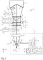
- a Cartesian xyz coordinate system is shown in the drawing, from which the respective positional relationship of the components shown in the figures results.
- Fig. 1 the y-direction runs vertically out of the drawing plane, the x-direction to the right and the z-direction downwards.
- Fig. 1 an embodiment 10 of a measuring device for the interferometric determination of a property of a shape z(x,y) (reference numeral 50) of a test surface 12 of a test object 14 is shown schematically.
- the determined property can be one or more derivatives dz/dx or dz/dy (reference numeral 52) of the shape z(x,y) of the test surface 12 or also the shape 50 of the test surface 12 itself.
- the shape of the test surface 12 or in particular also a desired shape of the test surface 12 can be non-spherical, in particular it can be designed as an aspheric or as a free-form surface.
- An aspheric surface is to be understood as a rotationally symmetrical surface that deviates from any sphere by at least 0.05 mm, in particular by at least 0.1 mm, by at least 1 mm or by at least 5 mm.
- Such an aspherical surface is also referred to in this text as a rotationally symmetrical asphere or simply as an asphere.
- a freeform surface is understood to be a shape with a deviation from any rotationally symmetrical asphere of at least 5 ⁇ m, in particular at least 10 ⁇ m.
- the freeform surface deviates from any sphere by at least 0.05 mm, in particular by at least 0.1 mm, by at least 1 mm or by at least 5 mm.
- the measuring device 10 is particularly suitable for the highly precise measurement of the optical surface of an aspherical mirror or a free-form mirror for microlithography with exposure radiation in the extreme ultraviolet (EUV) spectral range.
- EUV wavelength range extends to wavelengths below 100 nm and particularly concerns wavelengths of about 13.5 nm or about 6.8 nm. In order to reduce or correct errors in such optical surfaces, a shape determination down to the subnanometer range is necessary.
- the measuring device 10 is also suitable for measuring the surface of many other objects.
- the measuring device 10 comprises a beam generation and evaluation device 16, a splitting module 18, and a wavefront adaptation module configured as a diffractive optical element 20.
- the beam generation and evaluation device 16 comprises an irradiation device 22, which serves to generate an input wave 24 and has a radiation source 26 and a collimator lens 28.
- the radiation source 26 generates a measuring radiation 30 in the form of an expanding wave that is sufficiently coherent for interference.
- the radiation source 26 is a helium-neon laser with a wavelength of approximately 633 nm.
- the measuring radiation 30 can also have a different wavelength in the visible or non-visible wavelength range of electromagnetic radiation.
- the measuring radiation 30 generated by the radiation source 26 first passes through a beam splitter 31 and then the collimator lens 28.
- the input wave 24 generated by the irradiation device 22 is a plane wave, ie it has a plane wave front 25.
- the input wave 24 strikes the splitting module 18, which is configured to split the input wave 24 into two plane waves 32 and 34, ie waves with a plane wave front 33 and 35 respectively, with parallel propagation directions.
- the beam paths of the plane waves 32 and 34 are offset from one another transversely to their propagation direction in a splitting direction.
- the splitting is done by splitting the plane shaft 34 from the input wave 24, while the plane wave 32 is formed from the remaining radiation portion of the input wave 24.
- the Fig. 1 The splitting direction shown is the x-direction.
- the splitting module 18 comprises a beam direction splitting element in the form of a diffractive optical element 36 designed as a CGH and a direction adjustment element also in the form of a diffractive optical element 38 designed as a CGH.
- the beam direction splitting element is configured to generate two intermediate waves 40 and 42 with different propagation directions from the input wave 24.
- the intermediate waves 40 and 42 have plane wave fronts 41 and 43 tilted relative to one another.
- the generation of the intermediate waves 40 and 42 takes place in the embodiment according to Fig. 1 by splitting off the intermediate wave 42 with a slightly tilted propagation direction from the input wave 24, while the intermediate wave 40 is formed from the remaining radiation portion of the input wave 24.
- the wavefront adaptation module in the form of the diffractive optical element 20, for example designed as a CGH, is configured to adapt the respective wavefront of the plane waves 32 and 34 to a desired shape of the test surface 12 by diffraction in the first diffraction order and thus to generate, for example, two measuring waves 44 and 46, each with non-spherical wavefronts 45 and 47.
- the measuring waves 44 and 46 would impinge perpendicularly at every location on the test surface 12 and would be reflected back into themselves exactly if the test surface corresponded exactly to the desired shape. Deviations from the desired shape lead to an interference pattern in the superposition of the reflected measuring waves 44r and 46r, described in more detail below, i.e. the measuring waves 44 and 46 after their interaction with the test surface 12, with which the real surface shape can be determined with high precision.
- the reflected measuring waves 44r and 46r pass through the diffractive optical element 20, which functions as a wavefront adaptation module, and are converted back into mutually offset, parallel waves, which differ from the plane waves 32 and 34 only by deviations caused by the deviation of the test surface 12 from its desired shape.
- the reflected measuring waves 44r and 46r then run in the beam paths of the intermediate waves 40 and 42 and the input wave 24, but in the opposite direction to the radiation of the input wave 24.
- the measuring waves 44r and 46r are offset towards each other in such a way that the measuring waves 44r and 46r lie exactly on top of each other.
- the wave generated when passing through the diffractive optical element 38 in the 0th diffraction order of the measuring wave 44r is still referred to as the measuring wave 44r in the further beam path, while the 1st diffraction order of the measuring wave 44r represents an unused excess wave 72.
- the wave generated when passing through the diffractive optical element 38 in the 1st diffraction order of the measuring wave 46r is still referred to as the measuring wave 46r in the further beam path.
- the 0th diffraction order of the measuring wave 46r represents an unused excess wave 72.
- unused excess waves 72 are generated at the diffractive optical element 36.
- the diffractive optical elements 36 and 38 can be designed as blaze gratings, so that the undesired diffraction orders are strongly suppressed in their efficiencies.
- the reflected measuring waves 44r and 46r run in the same beam path after passing through the splitting module 18 in reverse, i.e. they are no longer offset from one another, and have wave fronts 60 and 62 that differ only by the deviations from planar wave fronts caused by the deviation of the test surface 12 from its nominal shape. Since the measuring waves 44 and 46 impinge on the test surface 12 slightly offset from one another, these deviations of the test surface 12 become noticeable through phase deviations of the wave fronts 60 and 62.
- the reflected measuring waves 44r and 46r are deflected in the beam generation and evaluation device 16 by the beam splitter 31 in the direction of a camera 58 after passing through the collimator lens 28. Both reflected measuring waves 44r and 46r pass through an eyepiece 54 and hit a detector 56 of the camera 58.
- the detector 56 comprises, for example, a CCD sensor and detects several interferograms 64 generated by the superposition of the reflected measuring waves 44r and 46r.
- the above-mentioned excess waves 72 have a beam path such that their radiation contributes nothing or only insignificantly to the interferograms 64, since these excess waves no longer hit the camera 58 at the same locations as the useful waves and therefore the condition for constructive interference is no longer met.
- the local excess waves and the local useful waves to the same source point arrive at different locations on the camera, or - the other way around expressed - the excess waves and the useful waves are no longer completely coherent with each other at a point on the camera 58, since they originate from different source locations.
- the recorded interferograms 64 are generated by changing the relative phase position between the two mutually offset plane waves 32 and 34 or the two measuring waves 44 and 46, the so-called phase shifting.
- This is done in the embodiment according to Fig. 1 by changing the distance between the diffractive optical element 38 serving as a direction adjustment element and the diffractive optical element 36 serving as a beam direction splitting element. The change in distance is brought about by axially displacing the diffractive optical element 38.
- a displacement device illustrated with a double arrow 39 is provided.
- the diffractive optical element 36 can also be axially displaced.
- the phase shifting can also be carried out by varying the wavelength ⁇ of the measuring radiation 30 or other measures.
- the phase shifting can also be carried out by a lateral displacement of the beam direction splitting element designed as a diffractive optical element 36 or the direction adjustment element designed as a diffractive optical element 38.
- the measuring device 10 is configured to vary the splitting direction of the two plane waves 32 and 34.
- the splitting module 18 is mounted axially, ie rotatably in relation to the direction of incidence of the input shaft 24.
- the splitting module 18 is rotated by 90°.
- a rotating device 65 illustrated with a double arrow, is provided. This arranges the splitting direction in the y-direction.
- a second set of interferograms 64 is determined with appropriate phase shifting.
- Both sets of recorded interferograms 64 are transmitted to an evaluation device 66, which comprises a first evaluation module 68 and a second evaluation module 70.
- first evaluation module 68 derivatives dz/dx and dz/dy (reference numeral 52) of the shape 50 of the test surface 12 are determined from the interferograms 64.
- the first set of interferograms 64 which were determined for the splitting in the x direction, is used to determine the derivatives dz/dx and the second set of interferograms 64, which were determined for the splitting in the y direction, is used to determine the derivatives dz/dy.
- the derivatives 52 are determined at the various coordinate points (x, y) of the test surface 12, i.e. at several locations on the test surface 12.
- the shape 50 of the test surface 12 is determined by integrating the determined derivatives dz/dx and dz/dy.
- the measuring device 10 is operated in air at normal pressure. This is possible because the interfering waves, namely the measuring waves 44r and 46r, travel through almost the same beam path and therefore air turbulence or air pressure fluctuations have hardly any influence on the measurement accuracy of the measuring device 10. An arrangement of the measuring device 10 in a vacuum, in particular in a high vacuum, can therefore be dispensed with.
- the size of the beam splitting of the intermediate waves 40 and 42 and thus the spatial resolution of the shape measurement can be varied by changing the distance between the diffractive optical elements 36 and 38.
- test surface 12 to be tested also serves as a reference surface and therefore no additional optical element is required as a reference mirror. This eliminates the effort required to manufacture and test such a reference mirror. In addition, possible errors in the measurement are eliminated. In other test optics with a reference or Fizeau element, the test and Reference wave have very different light paths and therefore experience large differences in error. Furthermore, the use of the test surface 12 as a reference surface enables a similarly large contrast regardless of the reflectivity of the test mirror.
- a further advantage of the measuring device 10 according to Fig. 1 is that the contrast is almost independent of the reflectivity of a mirror to be measured, in particular almost independent of whether the mirror is coated or not.
- a further advantage of the measuring device 10 according to Fig. 1 is that in addition to a coherent light source, an incoherent light source can also be used, with the advantage that disturbing reflections in the interferogram are strongly suppressed.
- a wavefront adaptation module 20 designed as a diffractive optical element or CGH
- Fig. 2 illustrates a qualification or calibration of the diffractive optical element 20 acting as a wavefront adaptation module.
- a flat calibration mirror 74 is arranged instead of the test object 14.
- the interferograms resulting from the superposition of the plane waves 32 and 34, here referred to as calibration waves 76 and 78, passing through the diffractive optical element 20 in the 0th diffraction order on the detector 56 are evaluated. From this, for example, material inhomogeneities in the substrate of the diffractive optical element 20 can be determined.
- Fig. 3 illustrates a qualification or calibration of the interferometer including the splitting module 18.
- the plane calibration mirror 74 is arranged instead of the diffractive optical element 20.
- the interferograms resulting from the superposition of the plane waves 32 and 34 reflected by the calibration mirror 74 on the detector 16 are evaluated. From this, for example, material inhomogeneities in the substrates of the diffractive optical elements 36 and 38 or other deviations in the beam path of the interferometer can be determined.
- the qualification according to Fig. 3 can be qualified according to Fig. 2 the error influence of the wavefront adaptation module can be separated from almost all other error contributions in the interferogram.
- FIG. 4 A further embodiment 110 of a measuring device for the interferometric determination of a property of a shape of a test surface 12 of a test object 14 is shown.
- the measuring device 110 differs from the measuring device 10 according to Fig. 1 only in the configuration of the splitting module 18, which in Fig. 4 designated by the reference numeral 118, as well as in the method of phase shifting.
- the beam generation and evaluation device 16 is in Fig. 4 only shown schematically.
- the splitting module 118 also comprises diffractive optical elements configured as beam direction splitting elements or direction adjustment elements, which are designated by the reference numerals 136 and 138.
- the diffractive optical elements 136 and 138 according to Fig. 4 differ from the diffractive optical elements 36 and 38 in that they are configured to be operated in the 1st diffraction order instead of in the 0th/1st diffraction order.
- This means that intermediate waves 140 and 142 are generated at the diffractive optical element 136 in the -1st and +1st diffraction order of the input wave 24 in the passage.
- the propagation directions of the intermediate waves 140 and 142 are thus oriented symmetrically to the propagation direction of the input wave 24.
- the 1st diffraction order of the intermediate wave 140 serves as the plane wave 32 and the 1st diffraction order of the intermediate wave 142 serves as the plane wave 34.
- FIG. 5 A further embodiment 210 of a measuring device for interferometrically determining a property of a shape of a test surface 12 of a test object 14 is shown.
- the measuring device 210 differs from the measuring device 110 according to Fig. 4 merely in that the diffractive optical elements 136 and 138 are tilted relative to the perpendicular arrangement to the beam direction of the input wave 24, advantageously by at least 1°, in particular by at least 10°.
- the tilting can be used to shift the phase, as in the embodiment according to Fig. 1 , by moving the diffractive optical element 138 serving as a direction adjustment element.
- a displacement device illustrated with a double arrow 39 is provided in the measuring device 210.
- Another important advantage of this tilted version of the splitting module is the suppression of the reflected light for reflection at the unstructured surfaces of the beam direction splitting element and the direction adjustment element in the non-tilted case, where the reflected light runs back into itself with the direction of the input wave 24.
- FIG. 6 A further embodiment 310 of a measuring device for interferometrically determining a property of a shape of a test surface 12 of a test object 14 is shown.
- the measuring device 310 differs from the measuring device 210 according to Fig. 5 merely in that the element serving as a beam splitting element is formed by a shear prism 336 instead of the diffractive optical element 136.
- the shear prism 336 is configured to split the input wave 24, which in this embodiment comprises unpolarized or diagonally polarized light, into two beams of differently polarized light that are tilted relative to one another and then function as the intermediate waves 140 and 142.
- Exemplary embodiments for the shear prism 336 may be designed as a Nomarski prism 336a or a Wollaston prism 336b.
- the unpolarized or diagonally polarized input wave 24 is separated into two beams that are linearly polarized at right angles to one another, which are deflected in different directions with respect to the input wave 24 and serve as intermediate waves 140 and 142.
- the intermediate waves 140 can be oriented symmetrically to the direction of propagation of the input wave 24.
- the phase shifting can be carried out in the measuring device 310, as in the measuring device 210 according to Fig. 5 , by axially displacing the diffractive optical element 138 serving as a direction adjustment element. Furthermore, the phase shifting can also be accomplished by laterally displacing the shear prism 336.
- variable phase delay element 339 can be used for phase shifting. This can be arranged between the diffractive optical element 118 of the splitting module 318 and the diffractive optical element 20 serving as the wavefront adaptation module 20.
- the variable phase delay element 339 also referred to as a phase retarder, can contain a liquid crystal, for example, and causes different phase retarding for wavefronts of different polarization. This thus causes different phase retarding for the two plane waves 32 and 34 or the two returning measuring waves 44r and 46r.
- FIG. 7 A further embodiment 410 of a measuring device for interferometrically determining a property of a shape of a test surface 12 of a test object 14 is shown.
- the measuring device 410 differs from the measuring device 310 according to Fig. 6 only in the sense that the direction adjustment element is also formed by a shear prism 438.
- the functionality of the shear prism 438 corresponds to that of the shear prism 336 in the opposite direction. That is, the shear prism 438 is arranged in the opposite orientation to the shear prism 336 of the same type.
- the splitting module 18 can also have a diffractive optical element as a beam direction splitting element and a shear prism as a direction adjustment element.
Landscapes
- Physics & Mathematics (AREA)
- General Physics & Mathematics (AREA)
- Chemical & Material Sciences (AREA)
- Analytical Chemistry (AREA)
- Engineering & Computer Science (AREA)
- Signal Processing (AREA)
- Geometry (AREA)
- Instruments For Measurement Of Length By Optical Means (AREA)
Applications Claiming Priority (1)
| Application Number | Priority Date | Filing Date | Title |
|---|---|---|---|
| DE102023206874.5A DE102023206874A1 (de) | 2023-07-20 | 2023-07-20 | Interferometrische Messvorrichtung |
Publications (1)
| Publication Number | Publication Date |
|---|---|
| EP4495538A1 true EP4495538A1 (fr) | 2025-01-22 |
Family
ID=91953748
Family Applications (1)
| Application Number | Title | Priority Date | Filing Date |
|---|---|---|---|
| EP24188820.5A Pending EP4495538A1 (fr) | 2023-07-20 | 2024-07-16 | Appareil de mesure interférométrique |
Country Status (4)
| Country | Link |
|---|---|
| US (1) | US20250027764A1 (fr) |
| EP (1) | EP4495538A1 (fr) |
| CN (1) | CN119334270A (fr) |
| DE (1) | DE102023206874A1 (fr) |
Cited By (1)
| Publication number | Priority date | Publication date | Assignee | Title |
|---|---|---|---|---|
| CN119984030A (zh) * | 2025-04-11 | 2025-05-13 | 深圳中科飞测科技股份有限公司 | 一种测量设备 |
Families Citing this family (2)
| Publication number | Priority date | Publication date | Assignee | Title |
|---|---|---|---|---|
| DE102023206874A1 (de) | 2023-07-20 | 2025-01-23 | Carl Zeiss Smt Gmbh | Interferometrische Messvorrichtung |
| DE102024126901A1 (de) * | 2024-09-19 | 2025-10-02 | Asml Netherlands B.V. | Messvorrichtung zum interferometrischen vermessen einer oberflächenform |
Citations (5)
| Publication number | Priority date | Publication date | Assignee | Title |
|---|---|---|---|---|
| DE102011004376B3 (de) | 2011-02-18 | 2012-06-21 | Carl Zeiss Smt Gmbh | Verfahren und Vorrichtung zum Bestimmen einer Form einer optischen Testfläche |
| WO2016188620A2 (fr) | 2015-05-22 | 2016-12-01 | Carl Zeiss Smt Gmbh | Dispositif de mesure interférométrique |
| DE102019210910A1 (de) * | 2019-07-23 | 2019-10-31 | Carl Zeiss Smt Gmbh | Messvorrichtung zur interferometrischen Bestimmung einer Oberflächenform |
| DE102021208880A1 (de) * | 2021-08-13 | 2023-02-16 | Carl Zeiss Smt Gmbh | Diffraktives optisches Element zur Generierung einer Prüfwelle |
| DE102023206874A1 (de) | 2023-07-20 | 2025-01-23 | Carl Zeiss Smt Gmbh | Interferometrische Messvorrichtung |
Family Cites Families (6)
| Publication number | Priority date | Publication date | Assignee | Title |
|---|---|---|---|---|
| DE19538747A1 (de) * | 1995-10-18 | 1997-04-24 | Johannes Prof Dr Schwider | Verfahren für die Bestimmung der Wellenaberrationen von Planwellen unter Benutzung von Gittershearinterferometern |
| DE102005041203A1 (de) * | 2005-08-31 | 2007-03-01 | Carl Zeiss Sms Gmbh | Vorrichtung und Verfahren zur interferometrischen Messung von Phasenmasken |
| CN102879111B (zh) * | 2012-10-10 | 2013-12-18 | 北京理工大学 | 用于扩束准直系统波面像差检测的装置及方法 |
| US10809055B2 (en) * | 2018-07-24 | 2020-10-20 | Kla Corporation | Apparatus and method for measuring topography and gradient of the surfaces, shape, and thickness of patterned and unpatterned wafers |
| DE102019214979A1 (de) * | 2019-09-30 | 2021-04-01 | Carl Zeiss Smt Gmbh | Messvorrichtung zur interferometrischen Bestimmung einer Oberflächenform |
| DE102020215540B4 (de) * | 2020-12-09 | 2022-07-07 | Uwe Schellhorn | Verfahren zum Bestimmen einer Abbildungsqualität eines Abbildungssystems, Vorrichtung sowie Projektionsbelichtungsanlage |
-
2023
- 2023-07-20 DE DE102023206874.5A patent/DE102023206874A1/de active Pending
-
2024
- 2024-07-16 EP EP24188820.5A patent/EP4495538A1/fr active Pending
- 2024-07-19 CN CN202410974284.8A patent/CN119334270A/zh active Pending
- 2024-07-19 US US18/778,483 patent/US20250027764A1/en active Pending
Patent Citations (5)
| Publication number | Priority date | Publication date | Assignee | Title |
|---|---|---|---|---|
| DE102011004376B3 (de) | 2011-02-18 | 2012-06-21 | Carl Zeiss Smt Gmbh | Verfahren und Vorrichtung zum Bestimmen einer Form einer optischen Testfläche |
| WO2016188620A2 (fr) | 2015-05-22 | 2016-12-01 | Carl Zeiss Smt Gmbh | Dispositif de mesure interférométrique |
| DE102019210910A1 (de) * | 2019-07-23 | 2019-10-31 | Carl Zeiss Smt Gmbh | Messvorrichtung zur interferometrischen Bestimmung einer Oberflächenform |
| DE102021208880A1 (de) * | 2021-08-13 | 2023-02-16 | Carl Zeiss Smt Gmbh | Diffraktives optisches Element zur Generierung einer Prüfwelle |
| DE102023206874A1 (de) | 2023-07-20 | 2025-01-23 | Carl Zeiss Smt Gmbh | Interferometrische Messvorrichtung |
Cited By (1)
| Publication number | Priority date | Publication date | Assignee | Title |
|---|---|---|---|---|
| CN119984030A (zh) * | 2025-04-11 | 2025-05-13 | 深圳中科飞测科技股份有限公司 | 一种测量设备 |
Also Published As
| Publication number | Publication date |
|---|---|
| CN119334270A (zh) | 2025-01-21 |
| DE102023206874A1 (de) | 2025-01-23 |
| US20250027764A1 (en) | 2025-01-23 |
Similar Documents
| Publication | Publication Date | Title |
|---|---|---|
| EP4495538A1 (fr) | Appareil de mesure interférométrique | |
| EP3298446B1 (fr) | Procédé de mesure et ensemble de mesure pour un système optique de formation d'image | |
| WO2008012091A2 (fr) | Procédé et dispositif de détermination de l'écart d'une forme réelle de la forme nominale d'une surface optique | |
| EP3887754B1 (fr) | Procédé et interféromètre pour déterminer une phase d'entrée et/ou une amplitude d'entrée d'un champ lumineux d'entrée | |
| WO2019063437A1 (fr) | Optique de compensation pour un système de mesure interférométrique | |
| EP3224570B1 (fr) | Procédé et dispositif de test interférométrique | |
| EP0045321A2 (fr) | Procédé et dispositif de mesure optique de distances | |
| CH693968A5 (de) | Verfahren und Vorrichtung fuer die Topographiepruefung von Oberflaechen. | |
| DE102021202909A1 (de) | Messvorrichtung zum interferometrischen Vermessen einer Oberflächenform | |
| DE102020207946A1 (de) | Messvorrichtung zur interferometrischen Bestimmung einer Oberflächenform | |
| DE102020203847A1 (de) | Interferometrische Messvorrichtung für Oberflächen | |
| EP3123247B1 (fr) | Dispositif de mesure servant à déterminer un paramètre de polarisation | |
| WO2024056501A1 (fr) | Procédé de traitement d'un élément de référence pour un interféromètre | |
| DE102015220588A1 (de) | Messverfahren und Messanordnung für ein abbildendes optisches System | |
| DE102012008745B4 (de) | Messvorrichtung | |
| DE102012100311B4 (de) | Verfahren und Anordnung zur Kalibrierung des Wellenfrontfehlers eines computergenerierten Hologramms für die Prüfung optischer Oberflächen | |
| DE102020213762B3 (de) | Diffraktives optisches Element für eine interferometrische Messvorrichtung | |
| EP4107480B1 (fr) | Dispositif de mesure de forme interférométrique | |
| DE10304822A1 (de) | Verfahren und Vorrichtung zur Bestimmung der Polarisationszustandsbeeinflussung durch ein optisches System und Analysator | |
| DE10325601B3 (de) | Schaltbares Punktlichtquellen-Array und dessen Verwendung in der Interferometrie | |
| DE102015209489A1 (de) | Interferometrische Messvorrichtung | |
| EP0079981B1 (fr) | Symétrisation de la phase d'un front d'ondes optiques | |
| DE102017210636A1 (de) | Messvorrichtung zur Vermessung eines lateralen Abbildungsfehlers eines abbildenden optischen Moduls | |
| WO2021228723A1 (fr) | Procédé de mesure par interférométrie d'une forme d'une surface | |
| DE102011086910A1 (de) | Verfahren und Messanordnung zum Vermessen einer Form einer Oberfläche eines Testobjektes |
Legal Events
| Date | Code | Title | Description |
|---|---|---|---|
| PUAI | Public reference made under article 153(3) epc to a published international application that has entered the european phase |
Free format text: ORIGINAL CODE: 0009012 |
|
| STAA | Information on the status of an ep patent application or granted ep patent |
Free format text: STATUS: THE APPLICATION HAS BEEN PUBLISHED |
|
| AK | Designated contracting states |
Kind code of ref document: A1 Designated state(s): AL AT BE BG CH CY CZ DE DK EE ES FI FR GB GR HR HU IE IS IT LI LT LU LV MC ME MK MT NL NO PL PT RO RS SE SI SK SM TR |
|
| STAA | Information on the status of an ep patent application or granted ep patent |
Free format text: STATUS: REQUEST FOR EXAMINATION WAS MADE |
|
| 17P | Request for examination filed |
Effective date: 20250626 |