EP4503493A1 - Procédé et appareil de détermination d'une relation entre des ports ptrs et des ports dmrs, support et produit - Google Patents
Procédé et appareil de détermination d'une relation entre des ports ptrs et des ports dmrs, support et produit Download PDFInfo
- Publication number
- EP4503493A1 EP4503493A1 EP23777865.9A EP23777865A EP4503493A1 EP 4503493 A1 EP4503493 A1 EP 4503493A1 EP 23777865 A EP23777865 A EP 23777865A EP 4503493 A1 EP4503493 A1 EP 4503493A1
- Authority
- EP
- European Patent Office
- Prior art keywords
- uplink
- dmrs port
- port
- information field
- ptrs
- Prior art date
- Legal status (The legal status is an assumption and is not a legal conclusion. Google has not performed a legal analysis and makes no representation as to the accuracy of the status listed.)
- Pending
Links
Images


Classifications
-
- H—ELECTRICITY
- H04—ELECTRIC COMMUNICATION TECHNIQUE
- H04L—TRANSMISSION OF DIGITAL INFORMATION, e.g. TELEGRAPHIC COMMUNICATION
- H04L5/00—Arrangements affording multiple use of the transmission path
- H04L5/003—Arrangements for allocating sub-channels of the transmission path
- H04L5/0048—Allocation of pilot signals, i.e. of signals known to the receiver
- H04L5/0051—Allocation of pilot signals, i.e. of signals known to the receiver of dedicated pilots, i.e. pilots destined for a single user or terminal
-
- H—ELECTRICITY
- H04—ELECTRIC COMMUNICATION TECHNIQUE
- H04L—TRANSMISSION OF DIGITAL INFORMATION, e.g. TELEGRAPHIC COMMUNICATION
- H04L5/00—Arrangements affording multiple use of the transmission path
- H04L5/0001—Arrangements for dividing the transmission path
- H04L5/0014—Three-dimensional division
- H04L5/0023—Time-frequency-space
-
- H—ELECTRICITY
- H04—ELECTRIC COMMUNICATION TECHNIQUE
- H04W—WIRELESS COMMUNICATION NETWORKS
- H04W72/00—Local resource management
- H04W72/20—Control channels or signalling for resource management
- H04W72/23—Control channels or signalling for resource management in the downlink direction of a wireless link, i.e. towards a terminal
- H04W72/232—Control channels or signalling for resource management in the downlink direction of a wireless link, i.e. towards a terminal the control data signalling from the physical layer, e.g. DCI signalling
Definitions
- the present disclosure relates to the field of communications, and more particularly to a method and apparatus for determining a relationship between a PTRS port and a DMRS port, medium and product.
- a Phase Tracking Reference Signal (PTRS) is designed, and the PTRS is used to estimate a Common Phase Error (CPE).
- CPE Common Phase Error
- a User Equipment adopts a layer mapping scheme of 1 Code Word (CW) to 1-4 layers; for the above-mentioned layer mapping scheme, the UE determines one or two uplink DMRS ports associated with an uplink PTRS port from 4 uplink DMRS ports, and sends a Demodulation Reference Signal (DMRS) from at most 4 antenna ports.
- CW Code Word
- Embodiments of the present disclosure provide a method and apparatus for determining a relationship between a PTRS port and a DMRS port, medium and product.
- the technical solution is as follows.
- a method for determining a relationship between a PTRS port and a DMRS port is provided, the method being performed by a terminal, and the method including:
- a method for determining a relationship between a PTRS port and a DMRS port is provided, the method being performed by a network device, the method including:
- an apparatus for determining a relationship between a PTRS port and a DMRS port including:
- an apparatus for determining a relationship between a PTRS port and a DMRS port including:
- a terminal which includes:
- a network device which includes:
- a computer-readable storage medium which has stored therein at least one instruction, at least one program, a set of codes, or a set of instructions loaded and executed by a processor to implement a method for determining a relationship between a PTRS port and a DMRS port as described in the various aspects above.
- a computer program product (or computer program) is provided, which includes computer instructions stored in a computer-readable storage medium; a processor of a computer device reads the computer instructions from the computer-readable storage medium, and executes the computer instructions to cause the computer device to perform the method for determining a relationship between a PTRS port and a DMRS port as described in the various aspects above.
- a chip which includes editable logic circuitry and/or program instructions for implementing, when the chip is running, a method for determining a relationship between a PTRS port and a DMRS port as described in the various aspects above.
- an uplink DMRS port associated with an uplink PTRS port is determined from at most 8 uplink DMRS ports based on downlink control information, and the method is used for supporting the implementation of relevant functions of the uplink PTRS port and the uplink DMRS port corresponding to the use of at most 8 antenna ports under different layer mapping schemes, for example, for supporting the terminal to use the uplink PTRS port and the uplink DMRS port corresponding to the use of 8 antenna ports to perform a co-phase error estimation under different layer mapping schemes.
- first, second, third, etc. may be used for the embodiments of the present disclosure to describe various information, such information should not be limited to these terms. These terms are only used to distinguish one type of information from another.
- the first information may also be referred to as the second information, and similarly, the second information may also be referred to as the first information, without departing from the scope of the embodiments of the present disclosure.
- the word “if' as used herein may be interpreted as "when://” or “whileising” or “in response to......”, and the word “in response to «” as used herein may also be interpreted as "in the case where......”.
- the terms “greater than” or “less than” are used herein when characterizing size relationships. However, for a person skilled in the art, it can be understood that: the term “greater than” also encompasses the meaning of “greater than or equal to”, and “less than” also encompasses the meaning of “less than and equal to”.
- FIG. 1 illustrates a block diagram showing a communication system provided by an exemplary embodiment of the present disclosure, which may include: an access network 12 and a user equipment 14.
- Network equipment 120 may be a base station, which is a type of device deployed in an access network to provide wireless communication functionality for user equipment (simply “terminals ") 14.
- a base station may include various forms of macro base stations, micro base stations, relay stations, access points, etc.
- the name of a device with a base station function may be different, for example, in a Long Term Evolution (LTE) system, it is called eNodeB or eNB; in the 5G NR (New Radio) system, it is called gNodeB or gNB.
- LTE Long Term Evolution
- gNodeB New Radio
- the means for providing wireless communication functionality for the user equipment 14 described above are collectively referred to as a network device.
- the communication interface between network devices 120 is an Xn interface.
- the user equipment 14 may include various hand-held devices with wireless communication capabilities, on-board devices, wearable devices, computing devices or other processing devices connected to wireless modems, as well as various forms of user equipment, Mobile Station (MS), terminal device, etc.
- MS Mobile Station
- the network device 120 and the user equipment 14 communicate with each other via some air interface technology, such as a Uu interface.
- the user equipment 14 supports performing a small data transmission procedure in an inactive state.
- an uplink communication scenario there are two communication scenarios between the network device 120 and the user equipment 14: an uplink communication scenario and a downlink communication scenario.
- the uplink communication is to transmit a signal to the network device 120; and the downlink communication is to transmit a signal to the user equipment 14.
- GSM Global System of Mobile Communication
- CDMA Code Division Multiple Access
- WCDMA Wideband Code Division Multiple Access
- GPRS General Packet Radio Service
- LTE Long Term Evolution
- FDD Frequency Division Duplex
- TDD Time Division Duplex
- LTE-A Advanced Long Term Evolution
- NR New Radio
- UMTS Universal Mobile Telecommunication System
- WiMAX Worldwide Interoperability for Microwave Access
- WLAN Wireless Local Area Networks
- Wi-Fi TM wireless network
- next generation communication system or other communication system etc.
- the conventional communication system supports a limited number of connections and is easy to implement, however, with the development of communication technology, the mobile communication system will support not only the conventional communication but also, for example, Device to Device (D2D) communication, Machine to Machine (M2M) communication, Machine Type Communication (MTC), Vehicle to Vehicle (V2V) communication and Vehicle to Everything (V2X) system, etc.
- D2D Device to Device
- M2M Machine to Machine
- MTC Machine Type Communication
- V2V Vehicle to Vehicle
- V2X Vehicle to Everything
- Embodiments of the present disclosure may also be applied to these communication systems.
- FIG. 2 is a flow chart showing a method for determining a relationship between a PTRS port and a DMRS port, which is applied to a terminal of the communication system shown in FIG 1 , according to an exemplary embodiment of the present disclosure, the method including the following steps.
- step 210 in case a target layer mapping scheme corresponding to n CWs is used, an association relationship between an uplink PTRS port and an uplink DMRS port based on downlink control information is determined, in which a maximum number of uplink DMRS ports is 8, a value of n is 1 or 2, and the target layer mapping scheme is a layer mapping scheme of type 1 or a layer mapping scheme of type 2.
- the above-mentioned layer mapping scenario for determining an association relationship between an uplink PTRS port and an uplink DMRS port includes any one of:
- a layer mapping scheme of type 1 includes 8 layer mapping schemes corresponding to 1 code word and 2 code words.
- the number of transmission layers corresponding to 1 code word after performing a layer mapping is greater than 0 and less than or equal to 4.
- the 2 code words include a first code word and a second code word; the first code word corresponds to a number of first transmission layers after performing the layer mapping, and the second code word corresponds to a number of second transmission layers after performing the layer mapping; in case of the layer mapping scheme of type 1, a layer number difference between the number of the first transmission layers and the number of the second transmission layers is 0 or 1, and a sum of the number of the first transmission layers and the number of the second transmission layers is greater than 4 and less than or equal to 8.
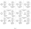
- layer mapping scheme of type 1 corresponding to 1 code word includes the following 4 types:
- a layer mapping scheme of type 1 corresponding to 2 code words includes the following 4 types:
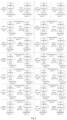
- a layer mapping scheme of type 2 includes 1 code word and 16 layer mapping schemes corresponding to 2 code words.
- the number of transmission layers corresponding to 1 code word after performing the layer mapping is greater than 0 and less than or equal to 4.
- a layer mapping scheme of type 2 corresponding to 1 code word includes the following 4 types:
- the 2 code words include a first code word and a second code word; the first code word corresponds to the number of first transmission layers after performing the layer mapping, and the second code word corresponds to the number of second transmission layers after performing the layer mapping; in case of the layer mapping scheme of type 2, the layer number difference between the number of the first transmission layers and the number of the second transmission layers is any value from 0 to 6, and the sum of the number of the first transmission layers and the number of the second transmission layers is greater than 1 and less than or equal to 8.
- the layer mapping scheme of type 1 it can be seen from the above-mentioned description of the layer mapping scheme of type 1 that the difference between the number of first transmission layers and the number of second transmission layers in the layer mapping scheme of type 1 is zero or one, and the difference between the number of layers between the number of first transmission layers and the number of second transmission layers in the layer mapping scheme of type 2 is any value from 0 to 6; and it can be seen that the layer mapping scheme of type 2 is more flexible than the layer mapping scheme of type 1.
- the layer number difference between the first number of transmission layers and the second number of transmission layers in the layer mapping scheme of type 2 can be any value from zero to six.
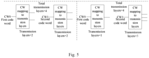
- CW0 maps to a transmission layer 1
- CW1 maps to transmission layers 2 to 7 for a total number of 8 transmission layers
- the layer number difference between the number of the first transmission layers and the number of the second transmission layers is six.
- the layer mapping scheme of type 2 includes at least one of:
- a layer mapping scheme of type 2 corresponding to 2 code words includes the following 12 types:
- a layer mapping scheme of type 2 corresponding to 2 code words includes the following 2 types in addition to those in FIG 4 :
- a layer mapping scheme of type 2 corresponding to 2 code words includes the following 4 types in addition to those in FIG 4 :
- a terminal determines one or two uplink DMRS ports associated with an uplink PTRS port from at most 8 uplink DMRS ports allocated correspondingly via a Physical Uplink Shared Channel (PUSCH)/Physical Uplink Control Channel (PUCCH) based on downlink control information (DCI).
- PUSCH Physical Uplink Shared Channel
- PUCCH Physical Uplink Control Channel
- the terminal determines an uplink DMRS port associated with the uplink PTRS port from at most 8 uplink DMRS ports correspondingly allocated by the PUSCH based on the indication of the information field in the downlink control information.
- the terminal determines a first uplink DMRS port associated with the first uplink PTRS port and a second uplink DMRS port associated with the second uplink PTRS port from at most 8 uplink DMRS ports correspondingly allocated by the PUSCH based on an indication of an information field in the downlink control information.
- the second uplink PTRS port refers to another one of the 2 uplink PTRS ports except the first uplink PTRS port; the second uplink DMRS port refers to another one of the at most 8 uplink DMRS ports except the first uplink DMRS port.
- the at most 8 uplink DMRS ports are assigned by the network device to the terminal.
- terminals are assigned by the network device to use all or part of the uplink DMRS ports. For example, there are 8 uplink DMRS ports available for allocation by a network device, and the network device allocates some or all the 8 uplink DMRS ports for a terminal to use; there are 12 uplink DMRS ports available for allocation by the network device, and the terminal is allocated to use some of the 12 uplink DMRS ports by the network device.
- a network device allocates all the 8 uplink DMRS ports for the terminal to use; or the network device allocates port 1, a port 3, a port 5 and a port 7 of the 8 uplink DMRS ports for the terminal to use; or the network device allocates ports 0 to 7 of the 12 uplink DMRS ports for the terminal to use; or, the terminals are assigned by the network device to use a port 0, a port 2, a port 4, a port 6, a port 8, and a port 10 of the 12 uplink DMRS ports.
- the number of uplink PTRS ports is configured by the network device for the terminal. For example, the terminal determines that the number of uplink PTRS ports is 1 or 2 based on the indication of downlink control information. For another example, a terminal receives high-layer signaling, such as Radio Resource Control (RRC) signaling, transmitted by a network device; based on the indication of the higher layer signaling, it is determined that the number of uplink PTRS ports is 1 or 2.
- RRC Radio Resource Control
- the number of uplink PTRS ports is determined by the terminal.
- the number of uplink PTRS ports is determined in any one of the following manners.
- the terminal receives downlink control information transmitted on a Media Access Control (MAC) layer.
- MAC Media Access Control
- the above-mentioned at most 8 uplink DMRS ports can be antenna ports mapped to the same antenna panel or different antenna panels; that is, the above-mentioned at most 8 uplink DMRS ports are antenna ports mapped onto M antenna panels, M being a positive integer less than or equal to 8.
- M being a positive integer less than or equal to 8.
- 4 of the 8 uplink DMRS ports are mapped onto a first antenna panel and the remaining 4 of the 8 uplink DMRS ports are mapped onto a second antenna panel.
- the above-mentioned at most 8 corresponds to a range from 0 to 8, for example, the at most 8 uplink DMRS ports refer to any one of 8 cases: 1 uplink DMRS port, 2 uplink DMRS ports, 3 uplink DMRS ports, 4 uplink DMRS ports, 5 uplink DMRS ports, 6 uplink DMRS ports, 7 uplink DMRS ports, and 8 uplink DMRS ports.
- the present embodiment provides a method for determining the relationship between a PTRS port and a DMRS port.
- an uplink DMRS port associated with an uplink PTRS port is determined from at most 8 uplink DMRS ports based on downlink control information, and the method is used for supporting the implementation of relevant functions of the uplink PTRS port and the uplink DMRS port corresponding to the use of at most 8 antenna ports under different layer mapping schemes, for example, for supporting the terminal to use the uplink PTRS port and the uplink DMRS port corresponding to the use of 8 antenna ports to perform a co-phase error estimation in case of the layer mapping scheme of type 1; for another example, an uplink PTRS port and an uplink DMRS port corresponding to 8 antenna ports are used to support a terminal to perform a CPE estimation in case of a layer mapping scheme of type 2.
- the number of CWs is 2, and at most 8 uplink DMRS ports are divided into 2 DMRS port groups, and the 2 CWs correspond to the 2 DMRS port groups on a one-to-one basis, and a first information field in downlink control information can be defined to indicate an association relationship between an uplink PTRS port and an uplink DMRS port.
- step 210 can be implemented by step 310 as follows.
- step 310 in response to the number of the uplink PTRS ports being 1, an association relationship between an uplink DMRS port in a DMRS port group corresponding to one of the CWs and the uplink PTRS port is determined based on a first information field in the DCI.
- 2 CWs include a first CW and a second CW
- 2 DMRS port groups include a first DMRS port group and a second DMRS port group
- the first CW corresponds to a first DMRS port group
- the second CW corresponds to a second DMRS port group.
- the terminal determines an association relationship between an uplink DMRS port in a first DMRS port group corresponding to a first CW and an uplink PTRS port based on a first information field in downlink control information; or, determines an association relationship between an uplink DMRS port in a second DMRS port group corresponding to a second CW and an uplink PTRS port based on a first information field in downlink control information.
- the first information field includes at most 3 bits.
- the first information field includes 2 bits, and for example, the first information field includes 3 bits.
- the first information field includes 2 bits.
- the first information field includes at most 3 bits.
- the value of M bits on the first information field can be used for indicating the port number of an uplink DMRS port allocated in a DMRS port group; for example, when the first information field includes 2 bits, and the port numbers of 4 uplink DMRS ports in 2 DMRS port groups are 0 to 3, the value of the 2 bits can be used for indicating the port numbers of the uplink DMRS ports.
- the value of M bits on the first information field can be used for indicating a sequencing position of an uplink DMRS port allocated in a DMRS port group; for example, when the first information field includes 3 bits, the uplink DMRS ports allocated in one DMRS port group are a port 0, a port 2, a port 4, a port 6, a port 8 and a port 10 in sequence, then "000” indicates a port 0, "001” indicates a port 2, “010” indicates a port 4, “011” indicates a port 6, "100” indicates a port 8 and "101” indicates a port 10; for another example, if the allocated uplink DMRS ports in a DMRS port group are a port 2, a port 5, a port 8 and a port 1, then “000” indicates a port 2, "001” indicates a port 5, “010” indicates a port 8 and "011” indicates a port 1.
- M bits are used for indicating one uplink DMRS port in a DMRS port group corresponding to a CW with a higher Modulation and Coding Scheme (MCS); that is, the first information field is used for indicating one uplink DMRS port in the DMRS port group corresponding to CW with a higher MCS.
- MCS Modulation and Coding Scheme
- M bits are used for indicating that an uplink DMRS port in the first DMRS port group corresponding to the first CW is associated with an uplink PTRS port.
- M bits are used for indicating one uplink DMRS port in the DMRS port group with the maximum number of allocated ports when the MCS of 2 CWs is the same; that is, the first information field is used for indicating one uplink DMRS port in the DMRS port group having the maximum number of allocated ports if the MCS of 2 CWs is the same.
- an uplink DMRS port in each DMRS port group is allocated by a network device, and M bits are used for indicating that an uplink DMRS port in the first DMRS port group is associated with an uplink PTRS port when the MCS level of 2 CWs is the same and the number of allocated ports in the first DMRS port group is greater than the number of allocated ports in the second DMRS port group.
- M bits are used for indicating one uplink DMRS port in the DMRS port group with the minimum number of allocated ports when the MCS of 2 CWs is the same; that is, the first information field is used for indicating one uplink DMRS port in the DMRS port group having the maximum number of allocated ports if the MCS of 2 CWs is the same.
- an uplink DMRS port in each DMRS port group is allocated by a network device, and M bits are used for indicating that an uplink DMRS port in the second DMRS port group is associated with an uplink PTRS port when the MCS level of 2 CWs is the same and the number of allocated ports in the second DMRS port group is greater than the number of allocated ports in the second DMRS port group.
- M bits are used for indicating one uplink DMRS port in a first DMRS port group corresponding to a first CW; that is, the first information field is used for indicating one uplink DMRS port in the first DMRS port group to which the first CW corresponds.
- M bits are used for indicating one uplink DMRS port in a second DMRS port group corresponding to a second CW; that is, the first information field is used for indicating one uplink DMRS port in the second DMRS port group to which the second CW corresponds.
- first and second in the second CW are only used for distinguishing 2 different CWs and do not include other meanings.
- the first CW is a first one of the 2 CWs
- the second CW is a second one of the 2 CWs
- the second CW is a first CW of the 2 CWs
- the first CW is a second CW of the 2 CWs.
- M bits are used for indicating one uplink DMRS port in a DMRS port group corresponding to the first CW of the 2 CWs when the MCS of the 2 CWs is the same; that is, the first information field is used for indicating one uplink DMRS port in the DMRS port group corresponding to the first CW of the 2 CWs if the MCS of the 2 CWs is the same.
- M when the number of uplink DMRS ports is 4, the value of M is 2; when the number of uplink DMRS ports is 8, M may have a maximum value of 3, for example M may be 2 or 3.
- the first information field includes 2 bits; and in case of the layer mapping scheme of type 2, the first information field includes at most 3 bits.
- the first information field includes 2 bits; and in case of the layer mapping scheme of type 2, the first information field includes at most 3 bits.
- the first information field includes at most 3 bits.
- an association relationship between an uplink DMRS port in a DMRS port group corresponding to one CW and an uplink PTRS port is determined based on an indication of 2 bits of a first information field; as another example, when using a layer mapping scheme of type 2 corresponding to 2 CWs, in response to the number of uplink PTRS ports being 1, an association relationship between an uplink DMRS port in a DMRS port group corresponding to one CW and an uplink PTRS port is determined based on an indication of 2 or 3 bits of the first information field.
- a terminal determines an uplink DMRS port associated with an uplink PTRS port from at most 8 uplink DMRS ports based on downlink control information when using a target layer mapping scheme corresponding to 2 code words, and the method is used for supporting the association of an uplink PTRS port on one of the at most 8 uplink DMRS ports in the layer mapping scheme corresponding to 2 code words.
- step 210 can be implemented by steps 410 to 420 as follows.
- step 410 in response to the number of the uplink PTRS ports being 2, an association relationship between the first uplink DMRS port in a DMRS port group corresponding to one of the CWs and the uplink PTRS port is determined based on a first information field in the DCI.
- 2 CWs include a first CW and a second CW
- 2 DMRS port groups include a first DMRS port group and a second DMRS port group
- the first CW corresponds to a first DMRS port group
- the second CW corresponds to a second DMRS port group.
- the 2 uplink PTRS ports include a first uplink PTRS port and a second uplink PTRS port; the first information field in the downlink control information is used for indicating a first uplink DMRS port associated with the first uplink PTRS port.
- the terminal determines an association relationship between a first uplink DMRS port in a first DMRS port group corresponding to a first CW and a first uplink PTRS port based on a first information field in downlink control information; or, determines the association relationship between the first uplink DMRS port in the second DMRS port group corresponding to the second CW and the first uplink PTRS port based on the first information field in the downlink control information.
- the first information field includes at most 3 bits.
- the first information field includes 2 bits, and for example, the first information field includes 3 bits.
- the first information field includes 2 bits.
- the first information field includes at most 3 bits.
- the value of M bits on the first information field may be used for indicating the port numbers of the uplink DMRS ports allocated in one DMRS port group; or, the value of M bits in the first information field may be used for indicating a sequencing position of the allocated uplink DMRS ports in a DMRS port group.
- M bits are used for indicating a first uplink DMRS port in a DMRS port group corresponding to a CW with a higher MCS; that is, the first information field is used for indicating the first uplink DMRS port in the DMRS port group corresponding to the CW with a higher MCS.
- M bits are used for indicating that the first uplink DMRS port in the second DMRS port group corresponding to the second CW is associated with the first uplink PTRS port.
- M bits are used for indicating the first uplink DMRS port in the DMRS port group with the maximum number of allocated ports when the MCS of 2 CWs is the same; that is, the first information field is used for indicating the first uplink DMRS port in the DMRS port group having the maximum number of allocated ports if the MCS of 2 CWs is the same.
- an uplink DMRS port in each DMRS port group is allocated by a network device, and M bits are used for indicating that the first uplink DMRS port in the second DMRS port group is associated with the first uplink PTRS port when the MCS level of 2 CWs is the same and the number of allocated ports in the first DMRS port group is smaller than the number of allocated ports in the second DMRS port group.
- M bits are used for indicating the first uplink DMRS port in the DMRS port group with the minimum number of allocated ports when the MCS of 2 CWs is the same; that is, the first information field is used for indicating the first uplink DMRS port in the DMRS port group having the minimum number of allocated ports if the MCS of 2 CWs is the same.
- an uplink DMRS port in each DMRS port group is allocated by a network device, and M bits are used for indicating that the first uplink DMRS port in the first DMRS port group is associated with the first uplink PTRS port when the MCS level of 2 CWs is the same and the number of allocated ports in the first DMRS port group is smaller than the number of allocated ports in the second DMRS port group.
- M bits are used for indicating the first uplink DMRS port in a first DMRS port group corresponding to a first CW; that is, the first information field is used for indicating the first uplink DMRS port in the first DMRS port group to which the first CW corresponds.
- M bits are used for indicating the first uplink DMRS port in a second DMRS port group corresponding to a second CW; that is, the first information field is used for indicating the first uplink DMRS port in the second DMRS port group to which the second CW corresponds.
- first and second in the second CW are only used for distinguishing 2 different CWs and do not include other meanings.
- the first CW is a first one of the 2 CWs
- the second CW is a second one of the 2 CWs
- the second CW is a first CW of the 2 CWs
- the first CW is a second CW of the 2 CWs.
- M bits are used for indicating the first uplink DMRS port in the DMRS port group corresponding to the first CW of the 2 CWs when the MCS of the 2 CWs is the same; that is, the first information field is used for indicating the first uplink DMRS port in the DMRS port group corresponding to the first CW of the 2 CWs if the MCS of the 2 CWs is the same.
- M when the number of uplink DMRS ports is 4, the value of M is 2; when the number of uplink DMRS ports is 8, M may have a maximum value of 3, for example M may be 2 or 3.
- the first information field includes 2 bits; and in case of the layer mapping scheme of type 2, the first information field includes 3 bits.
- the first information field includes 2 bits; and in case of the layer mapping scheme of type 2, the first information field includes 3 bits.
- an association relationship between the first uplink DMRS port in a DMRS port group corresponding to one CW and the first uplink PTRS port is determined based on an indication of 2 bits of a first information field; as another example, when using a layer mapping scheme of type 2 corresponding to 2 CWs, in response to the number of uplink PTRS ports being 2, an association relationship between the first uplink DMRS port in a DMRS port group corresponding to one CW and the first uplink PTRS port is determined based on an indication of 2 or 3 bits of the first information field.
- step 420 an association relationship between a second uplink DMRS port in the remaining DMRS port groups and a second uplink PTRS port is determined based on a default rule.
- the above default rules define a default association relationship between the second uplink PTRS port and the second uplink DMRS port.
- the terminal may determine a second uplink DMRS port associated with the second uplink PTRS port among the allocated uplink DMRS ports in the remaining DMRS port groups based on the above-mentioned default rule.
- the above-mentioned default rule may be pre-configured for a terminal by a network device; or, the default rules may be defined by a protocol.
- the above-mentioned remaining DMRS port groups refer to another DMRS port group except the DMRS port group where the first uplink DMRS port is located among the 2 DMRS port groups.
- the remaining DMRS port groups are a first DMRS port group or a second DMRS port group.
- the default rules include any one of the following.
- the second uplink DMRS port is an uplink DMRS port corresponding to the maximum port number in the remaining DMRS port groups.
- the uplink DMRS ports allocated in the first/second DMRS port group include a port 0 and a port 1, and the terminal determines an association between port 1 and the second uplink PTRS port.
- the second uplink DMRS port is an uplink DMRS port corresponding to the minimum port number in the remaining DMRS port groups;
- the uplink DMRS ports allocated in the first/second DMRS port group include a port 3, a port 5 and a port 7, and the terminal determines the association between the port 3 and the second uplink PTRS port.
- the second uplink DMRS port is one uplink DMRS port in the remaining DMRS port groups determined based on a predefined manner.
- the predefined manner includes: when the first uplink DMRS port is a G th uplink DMRS port in one of the DMRS port groups, the second uplink DMRS port is an H th uplink DMRS port in the remaining DMRS port groups, H is a remainder of a sum of G and 2 divided by P, P is the minimum number of ports corresponding to the 2 DMRS port groups, a value of G is a positive integer less than 8, and values of H and P are both positive integers not greater than 4.
- the second uplink DMRS port is an uplink DMRS port indicated by a network device.
- the network device indicates a fixed one of the 8 uplink DMRS ports as the second uplink DMRS port.
- a terminal determines a first uplink DMRS port associated with a first uplink PTRS port from uplink DMRS ports allocated for use in one DMRS port group based on downlink control information and determines a second uplink DMRS port associated with a second uplink PTRS port from uplink DMRS ports allocated for use in another DMRS port group based on a default rule when using a target layer mapping scheme corresponding to 2 code words.
- 2 uplink DMRS ports corresponding to the 2 uplink PTRS ports on a one-to-one basis are supported when at most 8 uplink DMRS ports are used in a layer mapping scheme corresponding to 2 code words.
- an information field in downlink control information indicates an uplink DMRS port in the at most 8 uplink DMRS ports associated with an uplink PTRS port.
- step 210 can be implemented by step 510 as follows.
- step 510 in response to the number of uplink PTRS ports being 1, an association relationship between one uplink DMRS port of the at most 8 uplink DMRS ports and an uplink PTRS port is determined based on a first information field in downlink control information.
- the first information field includes 2 bits, the 2 bits in the first information field being used for indicating an association relationship between one of the 4 uplink DMRS ports and an uplink PTRS port.
- the network device assigns the terminal to use ports 0 to 3 of the uplink DMRS ports, "00" for indicating a port 0, "01” for indicating a port 1, "10” for indicating a port 2, and "11” for indicating a port 3.
- the first information field includes at most 3 bits, the at most 3 bits in the first information field being used for indicating an association between one of the 8 uplink DMRS ports and an uplink PTRS port.
- the network device assigns the terminal to use ports 4 to 11 of the uplink DMRS ports, "000” for indicating a port 4, "001” for indicating a port 5, “010” for indicating a port 6, "011” for indicating a port 7, “100” for indicating a port 8, "101” for indicating a port 9, “110” for indicating a port 10, and "111” for indicating a port 11.
- an uplink DMRS port associated with an uplink PTRS port is determined from at most 8 uplink DMRS ports allocated for use by the terminal based on an information field in downlink control information, so as to support one uplink DMRS port corresponding to one uplink PTRS port when at most 8 uplink DMRS ports are used in the layer mapping scheme corresponding to 1 code word.
- step 210 can be implemented by step 610 as follows.
- step 610 in response to the number of uplink PTRS ports being 2, an association relationship between a first uplink DMRS port in at most 8 uplink DMRS ports and a first uplink PTRS port is determined based on a first information field in the DCI; and an association relationship between a second uplink DMRS port of the at most 8 uplink DMRS ports and a second uplink PTRS port is determined based on a second information field in the DCI.
- the 2 uplink PTRS ports include a first uplink PTRS port and a second uplink PTRS port.
- the first information field and the second information field respectively include 2 bits
- the terminal determines a first uplink DMRS port from the 4 uplink DMRS ports based on the indication of the 2 bits in the first information field and determines a second uplink DMRS port from 4 uplink DMRS ports based on the indication of 2 bits in the second information field, in which the second uplink DMRS port refers to other uplink DMRS ports except the first uplink DMRS port in the 4 uplink DMRS ports.
- the terminal determines a first uplink DMRS port in the 8 uplink DMRS ports based on the indication of the at most 3 bits in the first information field and determines a second uplink DMRS port from 8 uplink DMRS ports based on the indication of at most 3 bits in the second information field, in which the second uplink DMRS port refers to other uplink DMRS ports except the first uplink DMRS port in the 8 uplink DMRS ports.
- the above first information field is a PTRS-DMRS association field (i.e., a PTRS-DMRS association field).
- the second information field refers to bits of the MCS field other than the first information field or reserved codepoints (bits) of other information fields on the DCI.
- step 210 can be further implemented by step 710 as follows.
- step 710 in response to the number of uplink PTRS ports being 2, an association relationship between a first uplink DMRS port in at most 8 uplink DMRS ports and a first uplink PTRS port is determined based on a first information field in the DCI; and an association relationship between a second uplink DMRS port of the at most 8 uplink DMRS ports and a second uplink PTRS port is determined based on a codepoint of a second information field in the DCI.
- the first information field includes M bits, M having a value of 1 or 2.
- the second information field includes M bits, a codepoint of M bits being used for indicating 2 M uplink DMRS ports, M being a positive integer.
- the 2 uplink PTRS ports include a first uplink PTRS port and a second uplink PTRS port.
- the first information field and the second information field respectively include 2 bits
- the terminal determines a first uplink DMRS port from the 4 uplink DMRS ports based on the indication of the 2 bits in the first information field and determines a second uplink DMRS port from 4 uplink DMRS ports based on a codepoint of 2 bits and a correspondence in a second information field, in which the second uplink DMRS port refers to other uplink DMRS ports except the first uplink DMRS port in the 4 uplink DMRS ports and the correspondence refers to an association relationship between the second uplink PTRS port corresponding to the codepoint in the second information field and the uplink DMRS port.
- the terminal determines a first uplink DMRS port in the 8 uplink DMRS ports based on the indication of the at most 3 bits in the first information field and determines a second uplink DMRS port from 8 uplink DMRS ports based on a codepoint of at most 3 bits and a correspondence in a second information field, in which the second uplink DMRS port refers to other uplink DMRS ports except the first uplink DMRS port in the 8 uplink DMRS ports, and the correspondence refers to an association relationship between the second uplink PTRS port corresponding to the codepoint in the second information field and the uplink DMRS port.
- a codepoint of 2 bits can represent 4 uplink DMRS ports, and when the value of the codepoint is "00", a second uplink PTRS port is associated with an uplink DMRS port 3 in a correspondence; when the codepoint value is "01”, a second uplink PTRS port is associated with an uplink DMRS port 2 in a correspondence; when the codepoint value is "10”, a second uplink PTRS port is associated with an uplink DMRS port 1 in a correspondence; when the codepoint value is "11”, a second uplink PTRS port is associated with an uplink DMRS port 0 in a correspondence.
- Table 1 Codepoint value Uplink DMRS port associated with the second uplink PTRS port 00 Uplink DMRS port 3 01 Uplink DMRS port 2 10 Uplink DMRS port 1 11 Uplink DMRS port 0
- the above first information field is a PTRS-DMRS association field.
- the second information field refers to bits of the MCS field other than the first information field or reserved bits of other information fields on the DCI.
- the correspondence is defined by a network device; or, the correspondence is predefined.
- the above-mentioned M is obtained by a high-level configuration, or the above-mentioned M is obtained by a pre-definition.
- step 210 can be further implemented by step 810 as follows.
- step 810 in response to the number of uplink PTRS ports being 2, an association relationship between a first uplink DMRS port in at most 8 uplink DMRS ports and a first uplink PTRS port is determined based on a codepoint of a first information field in the DCI and a first correspondence; and an association relationship between a second uplink DMRS port in the at most 8 uplink DMRS ports and a second uplink PTRS port is determined based on a codepoint of a first information field in the DCI and a second correspondence.
- the first information field includes M bits, and the value of M is 2 or 3; a first correspondence is a mapping relationship between a codepoint corresponding to a first uplink PTRS port and an uplink DMRS port; the second correspondence is a mapping relationship between a codepoint corresponding to a second uplink PTRS port and an uplink DMRS port.
- an M-bit codepoint is used for indicating 2 M association combinations, each association combination corresponding to an uplink DMRS port associated with a first uplink PTRS port and an uplink DMRS port associated with a second uplink PTRS port.
- the uplink DMRS port 0 is associated with the uplink PTRS port 0 (i.e., a first uplink PTRS port) in a first correspondence
- the uplink DMRS port 4 is associated with the uplink PTRS port 1 (i.e., a second uplink PTRS port) in a second correspondence
- the uplink DMRS port 3 is associated with the uplink PTRS port 0 in the first correspondence
- the uplink DMRS port 5 is associated with the uplink PTRS port 1 in the second correspondence
- the uplink DMRS port 6 is associated with the uplink PTRS port 0 in the first correspondence
- the uplink DMRS port 3 is associated with the uplink PTRS port 1 in the second correspondence.
- Uplink DMRS port 0 Uplink DMRS port associated with uplink PTRS port 1 000 Uplink DMRS port 0 Uplink DMRS port 4 001 Uplink DMRS port 1 Uplink DMRS port 0 010 Uplink DMRS port 2 Uplink DMRS port 7 011 Uplink DMRS port 3 Uplink DMRS port 5 100 Uplink DMRS port 4 Uplink DMRS port 1 101 Uplink DMRS port 5 Uplink DMRS port 2 110 Uplink DMRS port 6 Uplink DMRS port 3 111 Uplink DMRS port 7 Uplink DMRS port 6
- uplink DMRS ports are divided into 2 DMRS port groups: a first port group and a second DMRS port group, and a first uplink PTRS port corresponding to the first DMRS port group and a second uplink PTRS port corresponding to the second DMRS port group are allocated.
- Each association combination corresponds to one uplink DMRS port in a first DMRS port group associated with a first uplink PTRS port and one uplink DMRS port in a second DMRS port group associated with a second uplink PTRS port.
- Uplink DMRS port 1 Uplink DMRS port 0 Uplink DMRS port associated with uplink PTRS port 1 000 Uplink DMRS port 0 Uplink DMRS port 1 001 Uplink DMRS port 2 Uplink DMRS port 3 010 Uplink DMRS port 4 Uplink DMRS port 5 011 Uplink DMRS port 6 Uplink DMRS port 7 100 Uplink DMRS port 0 Uplink DMRS port 3 101 Uplink DMRS port 2 Uplink DMRS port 7 110 Uplink DMRS port 4 Uplink DMRS port 5 111 Uplink DMRS port 6 Uplink DMRS port 1
- first correspondence and the second correspondence are defined by a network device; or, the first correspondence and the second correspondence are predefined.
- the above-mentioned M is obtained by a high-level configuration, or the above-mentioned M is obtained by a pre-definition.
- the first information field is a PTRS-DMRS association field.
- a terminal determines a first uplink DMRS port associated with a first uplink PTRS port and a second uplink DMRS port associated with a second uplink PTRS port from at most 8 uplink DMRS ports allocated for use by the terminal based on one or two information fields in downlink control information when using a target layer mapping scheme corresponding to 1 code word, so as to support 2 uplink DMRS ports corresponding to the 2 uplink PTRS ports on a one-to-one basis when at most 8 uplink DMRS ports are used in the layer mapping scheme corresponding to the 1 code word.
- an information field in the downlink control information can be defined to indicate an uplink DMRS port in the at most 8 uplink DMRS ports associated with an uplink PTRS port.
- step 210 can be implemented by step 910 as follows.
- step 910 in response to the number of uplink PTRS ports being 2, an association relationship between a first uplink DMRS port of the at most 8 uplink DMRS ports and a first uplink PTRS port, and an association relationship between a second uplink DMRS port of the at most 8 uplink DMRS ports and a second uplink PTRS port are determined based on a first information field in the DCI.
- the first information field includes 2M or 2 (M-1) bits, and M has a value of 2 or 3.
- M Most Significant Bytes
- LSB Least Significant Bytes
- the M most significant bytes are used for indicating a second uplink DMRS port of the 2 M uplink DMRS ports
- the M least significant bytes are used for indicating a first uplink DMRS port of the 2 M uplink DMRS ports.
- the value of 3 bits of a highly significant byte is used for indicating one uplink DMRS port (i.e., a first uplink DMRS port) in the 8 uplink DMRS ports associated with a first uplink PTRS port; the value of 2 bits of the lowly significant bytes is used for indicating another uplink DMRS port (i.e., a second uplink DMRS port) in the 8 uplink DMRS ports associated with the second uplink PTRS port.
- 8 uplink DMRS ports are divided into 2 DMRS port groups: a first DMRS port group and a second DMRS port group.
- Each DMRS port group may include 4 uplink DMRS ports.
- the values of 2 bits of highly significant bytes are used for indicating an uplink DMRS port (i.e., a first uplink DMRS port) associated with a first uplink PTRS port in a first DMRS port group; the value of 2 bits of the lowly significant bytes is used for indicating one uplink DMRS port (i.e., a second uplink DMRS port) associated with the second uplink PTRS port in the second DMRS port group.
- the second DMRS port group is a DMRS port group of the two DMRS port groups except the first DMRS port group.
- the terminal in response to the 4 bits being "0001", determines that the first uplink DMRS port associated with the first uplink PTRS port 0 is the uplink DMRS port 0, and the second uplink DMRS port associated with the second uplink PTRS port 1 is the uplink DMRS port 1; in response to the 4 bits being "0110", the terminal determines that the first uplink DMRS port associated with the first uplink PTRS port 0 is an uplink DMRS port 1, and the second uplink DMRS port associated with the second uplink PTRS port 1 is an uplink DMRS port 2; the terminal, in response to the 4 bits being "1011", determines that a first uplink DMRS port associated with a first uplink PTRS port 0 is an uplink DMRS port 2, and a second uplink DMRS port associated with a second uplink PTRS port 1 is an uplink DMRS port
- Table 4 2 bits of MSB Uplink DMRS port associated with uplink PTRS port 0 2 bits of LSB Uplink DMRS port associated with uplink PTRS port 1 00 Uplink DMRS port 0 01 Uplink DMRS port 1 01 Uplink DMRS port 1 10 Uplink DMRS port 2 10 Uplink DMRS port 2 11 Uplink DMRS port 3 11 Uplink DMRS port 3 00 Uplink DMRS port 0
- the first information field is a PTRS-DMRS association field.
- a terminal determines a first uplink DMRS port associated with a first uplink PTRS port and a second uplink DMRS port associated with a second uplink PTRS port from at most 8 uplink DMRS ports allocated for use by the terminal based on an information field in downlink control information when using a target layer mapping scheme corresponding to one or two code words.
- 2 uplink DMRS ports corresponding to two uplink PTRS ports on a one-to-one basis when using at most 8 uplink DMRS ports with a layer mapping scheme corresponding to 1 code word and 2 uplink DMRS ports corresponding to two uplink PTRS ports on a one-to-one basis when using at most 8 uplink DMRS ports with a layer mapping scheme corresponding to 2 code words can be simultaneously supported.
- FIG 14 is a flow chart showing a method for determining a relationship between a PTRS port and a DMRS port, which is applied to a network device of the communication system shown in FIG 1 , according to an exemplary embodiment of the present disclosure. he method includes the following steps.
- step 1010 downlink control information is sent to a terminal, in which the downlink control information is used for indicating an association relationship between an uplink PTRS port and an uplink DMRS port when the terminal adopts a target layer mapping scheme corresponding to n code words, in which the maximum number of uplink DMRS ports is 8; N has a value of 1 or 2; the target layer mapping scheme is a layer mapping scheme of type 1, or a layer mapping scheme of type 2.
- Each type of layer mapping scheme includes two cases when the number of code words is 1 and 2.
- a layer mapping scheme of type 1 when the number of code words is 1, the number of transmission layers corresponding to 1 code word after performing the layer mapping is greater than 0 and less than or equal to 4; when the number of code words is 2, 2 code words include a first code word and a second code word, the first code word corresponds to the number of first transmission layers after performing the layer mapping, and the second code word corresponds to the number of second transmission layers after performing the layer mapping, then the difference between the number of first transmission layers and the number of second transmission layers is 0 or 1, and the sum of the number of first transmission layers and the number of second transmission layers is greater than 4 and less than or equal to 8.
- the number of code words when the number of code words is 1, the number of transmission layers corresponding to 1 code word after performing the layer mapping is greater than 0 and less than or equal to 4; when the number of code words is 2, the 2 code words include a first code word and a second code word, the first code word corresponds to the number of first transmission layers after performing the layer mapping, and the second code word corresponds to the number of second transmission layers after performing the layer mapping, then the difference between the number of first transmission layers and the number of second transmission layers is any value from 0 to 6, and the sum of the number of first transmission layers and the number of second transmission layers is greater than 4 and less than or equal to 8.
- the number of code words when the number of code words is 1, the number of transmission layers corresponding to 1 code word after performing the layer mapping is greater than 0 and less than or equal to 3; when the number of code words is 2, the 2 code words include a first code word and a second code word, the first code word corresponds to the number of first transmission layers after performing the layer mapping, and the second code word corresponds to the number of second transmission layers after performing the layer mapping, then the difference between the number of first transmission layers and the number of second transmission layers is any value from 0 to 6, and the sum of the number of first transmission layers and the number of second transmission layers is greater than 3 and less than or equal to 8.
- the 2 code words include a first code word and a second code word, the first code word corresponds to the number of first transmission layers after performing the layer mapping, and the second code word corresponds to the number of second transmission layers after performing the layer mapping, then the difference between the number of first transmission layers and the number of second transmission layers is any value from 0 to 6, and the sum of the number of first transmission layers and the number of second transmission layers is greater than 1 and less than or equal to 8.
- the number of code words is 2, and the manner for a network device to indicate an uplink PTRS port association relationship may include any one of the following.
- the number of uplink PTRS ports is 1, the first information field in the DCI includes M bits, and the M bits are used for indicating an association relationship between an uplink DMRS port in a DMRS port group corresponding to a CW and an uplink PTRS port.
- M bits are used for indicating one uplink DMRS port in a DMRS port group corresponding to a CW with a higher MCS, that is to say, a first information field is used for indicating one uplink DMRS port in a DMRS port group corresponding to a CW with a higher MCS.
- M bits are used for indicating one uplink DMRS port in the DMRS port group with the maximum number of allocated ports when the MCS of 2 CWs is the same; that is, the first information field is used for indicating one uplink DMRS port in the DMRS port group having the maximum number of allocated ports if the MCS of 2 CWs is the same.
- M bits are used for indicating one uplink DMRS port in the DMRS port group with the minimum number of allocated ports when the MCS of 2 CWs is the same; that is, the first information field is used for indicating one uplink DMRS port in the DMRS port group having the minimum number of allocated ports if the MCS of 2 CWs is the same.
- M bits are used for indicating one uplink DMRS port in a first DMRS port group corresponding to a first CW; that is, the first information field is used for indicating one uplink DMRS port in the first DMRS port group to which the first CW corresponds.
- M bits are used for indicating one uplink DMRS port in a second DMRS port group corresponding to a second CW; that is, the first information field is used for indicating one uplink DMRS port in the second DMRS port group to which the second CW corresponds.
- M bits are used for indicating one uplink DMRS port in a DMRS port group corresponding to the first CW of the 2 CWs when the MCS of the 2 CWs is the same; that is, the first information field is used for indicating one uplink DMRS port in the DMRS port group corresponding to the first CW of the 2 CWs if the MCS of the 2 CWs is the same.
- the first information field includes at most 3 bits.
- M has a maximum value of 3, such as 2 or 3.
- the first information field includes 2 bits; and in case of the layer mapping scheme of type 2, the first information field includes at most 3 bits.
- the first information field includes 2 bits; and in case of the layer mapping scheme of type 2, the first information field includes at most 3 bits.
- the number of the uplink PTRS ports is 2, and a first information field in the DCI is used for indicating an association relationship between a first uplink DMRS port in a DMRS port group corresponding to one of the CWs and a first uplink PTRS port; in which the first information field includes M bits.
- M bits are used for indicating a first uplink DMRS port in a DMRS port group corresponding to a CW with a higher MCS; that is, the first information field is used for indicating the first uplink DMRS port in the DMRS port group corresponding to CW with higher MCS.
- M bits are used for indicating the first uplink DMRS port in the DMRS port group with the maximum number of allocated ports when the MCS of 2 CWs is the same; that is, the first information field is used for indicating the first uplink DMRS port in the DMRS port group having the maximum number of allocated ports if the MCS of 2 CWs is the same.
- M bits are used for indicating the first uplink DMRS port in the DMRS port group with the minimum number of allocated ports when the MCS of 2 CWs is the same; that is, the first information field is used for indicating the first uplink DMRS port in the DMRS port group having the minimum number of allocated ports if the MCS of 2 CWs is the same.
- M bits are used for indicating the first uplink DMRS port in a first DMRS port group corresponding to a first CW; that is, the first information field is used for indicating the first uplink DMRS port in the first DMRS port group to which the first CW corresponds.
- M bits are used for indicating the first uplink DMRS port in a second DMRS port group corresponding to a second CW; that is, the first information field is used for indicating the first uplink DMRS port in the second DMRS port group to which the second CW corresponds.
- M bits are used for indicating the first uplink DMRS port in the DMRS port group corresponding to the first CW of the 2 CWs when the MCS of the 2 CWs is the same; that is, the first information field is used for indicating the first uplink DMRS port in the DMRS port group corresponding to the first CW of the 2 CWs if the MCS of the 2 CWs is the same.
- the first information field includes at most 3 bits.
- M has a maximum value of 3, such as 2 or 3.
- the first information field includes 2 bits; and in case of the layer mapping scheme of type 2, the first information field includes at most 3 bits.
- the first information field includes 2 bits; and in case of the layer mapping scheme of type 2, the first information field includes at most 3 bits.
- the first information field includes at most 3 bits.
- a layer mapping scheme of type 1 corresponding to 2 CWs is used and the number of uplink PTRS ports is 2, an association relationship between a first uplink DMRS port in a DMRS port group corresponding to one CW and a first uplink PTRS port is indicated based on 2 bits of a first information field; for another example, when using a layer mapping scheme of type 2 corresponding to 2 CWs and the number of uplink PTRS ports being 2, an association relationship between a first uplink DMRS port in a DMRS port group corresponding to one CW and a first uplink PTRS port is indicated based on 2 or 3 bits of a first information field.
- the network device pre-configures a default rule for the terminal, and the default rule includes any one of the following.
- the second uplink DMRS port is an uplink DMRS port corresponding to the maximum port number in the remaining DMRS port groups.
- the second uplink DMRS port is an uplink DMRS port corresponding to the minimum port number in the remaining DMRS port groups.
- the second uplink DMRS port is one uplink DMRS port in the remaining DMRS port groups determined based on a predefined manner.
- the second uplink DMRS port is an uplink DMRS port indicated by a network device.
- the predefined manner includes: when the first uplink DMRS port is a G th uplink DMRS port in one of the DMRS port groups, the second uplink DMRS port is an H th uplink DMRS port in the remaining DMRS port groups, H is a remainder of a sum of G and 2 divided by P, P is the minimum number of ports corresponding to the 2 DMRS port groups, a value of G is a positive integer less than 8, and values of H and P are both positive integers not greater than 4.
- the number of code words is 1, and the manner for a network device to indicate an uplink PTRS port association relationship may include any one of the following.
- the first information field in the DCI includes M bits for indicating an association relationship between one of the 2 M uplink DMRS ports and the uplink PTRS port.
- the number of uplink PTRS ports is 2, and a first information field in the DCI is used for indicating an association relationship between a first uplink DMRS port in the 2 M uplink DMRS ports and the first uplink PTRS port; a second information field in the DCI is used for indicating an association relationship between a second uplink DMRS port in the 2 M uplink DMRS ports and a second uplink PTRS port; in which the first information field includes M bits.
- the second information field refers to bits of the MCS field other than the first information field or reserved bits of other information fields on the DCI.
- a first information field in the DCI is used for indicating an association relationship between a first uplink DMRS port in the 2 M uplink DMRS ports and the first uplink PTRS port; a codepoint of a second information field in the DCI is used for indicating an association relationship between a second uplink DMRS port in the 2 M uplink DMRS ports and a second uplink PTRS port; in which the first information field includes M bits.
- the second information field refers to bits of the MCS field other than the first information field or reserved bits of other information fields on the DCI.
- a codepoint of a first information field in the DCI is used for indicating an association relationship between a first uplink DMRS port in 2 M uplink DMRS ports and a first uplink PTRS port in a first correspondence; a codepoint of a first information field in the DCI is used for indicating an association relationship between a second uplink DMRS port in 2 M uplink DMRS ports and a second uplink PTRS port in a second correspondence; in which the first information field includes M bits; the first correspondence is a mapping relationship between a codepoint corresponding to a first uplink PTRS port and an uplink DMRS port; the second correspondence is a mapping relationship between a codepoint corresponding to a second uplink PTRS port and an uplink DMRS port.
- the number of code words is 1 or 2
- the manner for a network device to indicate an uplink PTRS port association relationship may include the following.
- the number of uplink PTRS ports is 2, and a first information field in the DCI includes 2M bits, in which the 2M bits are used for indicating an association relationship between a first uplink DMRS port in the 2 M uplink DMRS ports and a first uplink PTRS port and an association relationship between a second uplink DMRS port and a second uplink PTRS port.
- the 2M bits include M most significant bytes and M least significant bytes; the M most significant bytes are used for indicating a first uplink DMRS port, and the M least significant bytes are used for indicating a second uplink DMRS port; or, the M most significant bytes are used for indicating the second uplink DMRS port and the M least significant bytes are used for indicating the first uplink DMRS port.
- the value of M is 2 or 3.
- the above first information field is a PTRS-DMRS association field.
- the network device transmits downlink control information to a terminal, so that when a terminal uses a target layer mapping scheme corresponding to n code words, an uplink DMRS port associated with an uplink PTRS port is determined from at most 8 uplink DMRS ports based on downlink control information, and the method is used for supporting the implementation of relevant functions of the uplink PTRS port and the uplink DMRS port corresponding to the use of at most 8 antenna ports with different layer mapping schemes, for example, for supporting the terminal to use the uplink PTRS port and the uplink DMRS port corresponding to the use of 8 antenna ports to perform a co-phase error estimation with different layer mapping schemes.
- FIG 15 illustrates a block diagram showing an apparatus for determining a relationship between a PTRS port and a DMRS port, which may be implemented as part or the whole UE through software, hardware, or a combination thereof, according to an exemplary embodiment of the present disclosure, the apparatus including a first processing module 1110.
- the first processing module 1110 is configured to determine an association relationship between an uplink PTRS port and an uplink DMRS port based on DCI in case of adopting a target layer mapping scheme corresponding to n CWs.
- a maximum number of uplink DMRS ports is 8, a value of n is 1 or 2, and the target layer mapping scheme is a layer mapping scheme of type 1 or a layer mapping scheme of type 2.
- the 2 code words include a first code word and a second code word; the first code word corresponds to the number of first transmission layers after performing layer mapping, and the second code word corresponds to the number of second transmission layers after performing layer mapping; In case of the layer mapping scheme of type 1, the layer number difference between the number of the first transmission layers and the number of the second transmission layers is 0 or 1.
- the layer number difference between the number of the first transmission layers and the number of the second transmission layers is any value from 0 to 6.
- the sum of the number of the first transmission layers and the number of the second transmission layers is greater than 4 and less than or equal to 8.
- the sum of the number of the first transmission layers and the number of the second transmission layers is greater than 4 and less than or equal to 8; or, the sum of the number of the first transmission layers and the number of the second transmission layers is greater than 3 and less than or equal to 8; or, the sum of the first number of transmission layers and the second number of transmission layers is greater than 1 and less than or equal to 8.
- the 8 uplink DMRS ports are divided into 2 DMRS port groups, and the 2 CWs correspond to the 2 DMRS port groups on a one-to-one basis.
- the first processing module 1110 is configured to, in response to the number of the uplink PTRS ports being 1, determine an association relationship between an uplink DMRS port in a DMRS port group corresponding to one of the CWs and the uplink PTRS port based on a first information field in the DCI; in which the first information field includes at most 3 bits.
- the first information field is used for indicating one uplink DMRS port in a DMRS port group corresponding to the CW with a higher MCS;
- the first information field includes 2 bits.
- the first information field includes at most 3 bits.
- the 8 uplink DMRS ports are divided into 2 DMRS port groups, and the 2 CWs correspond to the 2 DMRS port groups on a one-to-one basis.
- the first processing module 1110 is configured to, in response to the number of the uplink PTRS ports being 2, determine an association relationship between the first uplink DMRS port in a DMRS port group corresponding to one of the CWs and the first uplink PTRS port based on a first information field in the DCI; in which the first information field includes at most 3 bits.
- the first information field is used for indicating the first uplink DMRS port in the DMRS port group corresponding to the CW with a higher MCS;
- the first information field includes 2 bits.
- the first information field includes at most 3 bits.
- the first processing module 1110 is configured to determine an association relationship between a second uplink DMRS port in the remaining DMRS port groups and a second uplink PTRS port based on a default rule.
- the default rules include any one of:
- the predefined manner includes the following.
- the second uplink DMRS port is an H th uplink DMRS port in the remaining DMRS port groups
- H is a remainder of a sum of G and 2 divided by P
- P is the minimum number of ports corresponding to the 2 DMRS port groups
- a value of G is a positive integer less than 8
- values of H and P are both positive integers not greater than 4.
- the number of transmission layers corresponding to 1 code word after performing a layer mapping is greater than 0 and less than or equal to 4.
- the number of transmission layers corresponding to 1 code word after performing a layer mapping is greater than 0 and less than or equal to 4; or, the number of transmission layers corresponding to the 1 CW after performing the layer mapping is greater than 0 and less than or equal to 3; or, the number of transmission layers corresponding to the 1 CW after performing the layer mapping is 1.
- the first processing module 1110 is configured to, in response to the number of uplink PTRS ports being 1, determine an association relationship between an uplink DMRS port of the 8 uplink DMRS ports and the uplink PTRS port based on a first information field in the DCI when the number of CWs is 1; the first information field includes 3 bits.
- the first processing module 1110 is configured to, in response to the number of the uplink PTRS ports being 2, determine an association relationship between a first uplink DMRS port in the 8 uplink DMRS ports and a first uplink PTRS port based on a first information field in the DCI when the number of the CWs is 1, the first information field including 3 bits; and determine an association relationship between a second uplink DMRS port in the 8 uplink DMRS ports and a second uplink PTRS port based on a second information field in the DCI.
- the first processing module 1110 is configured to, in response to the number of the uplink PTRS ports being 2, determine an association relationship between a first uplink DMRS port in the 8 uplink DMRS ports and a first uplink PTRS port based on a first information field in the DCI when the number of the CWs is 1, the first information field including 3 bits; and determine an association relationship between a second uplink DMRS port in the 8 uplink DMRS ports and a second uplink PTRS port based on a codepoint of a second information field in the DCI.
- the second information field refers to bits of a MCS field or reserved bits of other information fields on the DCI than the first information field.
- the first processing module 1110 is configured to, in response to the number of uplink PTRS ports being 2, determine an association relationship between a first uplink DMRS port in the 8 uplink DMRS ports and a first uplink PTRS port based on a codepoint of a first information field in the DCI and a first correspondence when the number of CWs is 1; and determine an association relationship between a second uplink DMRS port in the 8 uplink DMRS ports and a second uplink PTRS port based on a codepoint of a first information field in the DCI and a second correspondence.
- the first information field includes 3 bits; the first correspondence is a mapping relationship between a codepoint corresponding to the first uplink PTRS port and an uplink DMRS port; the second correspondence is a mapping relationship between a codepoint corresponding to the second uplink PTRS port and the uplink DMRS port.
- the first processing module 1110 is configured to, in response to the number of the uplink PTRS ports being 2, determine an association relationship between a first uplink DMRS port in the 8 uplink DMRS ports and a first uplink PTRS port and an association relationship between a second uplink DMRS port in the 8 uplink DMRS ports and a second uplink PTRS port based on a first information field in the DCI; in which the first information field includes 6 bits.
- the 6 bits include 3 most significant bytes MSB and 3 least significant bytes LSB.
- the 3 most significant bytes are used for indicating the first uplink DMRS port, and the 3 least significant bytes are used for indicating the second uplink DMRS port; or, the 3 most significant bytes are used for indicating the second uplink DMRS port and the 3 least significant bytes are used for indicating the first uplink DMRS port.
- FIG 16 illustrates a block diagram showing an apparatus for determining a relationship between a PTRS port and a DMRS port, which may be implemented as part or the whole network device through software, hardware, or a combination thereof, according to an exemplary embodiment of the present disclosure, the apparatus including a second transmission module 1120.
- the second transmission module 1120 is configured to transmit downlink control information to a terminal, in which the downlink control information is used for indicating an association relationship between an uplink PTRS port and an uplink DMRS port of the terminal when using a target layer mapping scheme corresponding to n code words.
- a maximum number of uplink DMRS ports is 8, a value of n is 1 or 2, and the target layer mapping scheme is a layer mapping scheme of type 1 or a layer mapping scheme of type 2.
- the 2 code words include a first code word and a second code word; the first code word corresponds to the number of first transmission layers after performing the layer mapping, and the second code word corresponds to the number of second transmission layers after performing the layer mapping.
- the layer number difference between the number of the first transmission layers and the number of the second transmission layers is 0 or 1.
- the layer number difference between the number of the first transmission layers and the number of the second transmission layers is any value from 0 to 6.
- the sum of the number of the first transmission layers and the number of the second transmission layers is greater than 4 and less than or equal to 8.
- the sum of the number of the first transmission layers and the number of the second transmission layers is greater than 4 and less than or equal to 8; or, the sum of the number of the first transmission layers and the number of the second transmission layers is greater than 3 and less than or equal to 8; or, the sum of the first number of transmission layers and the second number of transmission layers is greater than 1 and less than or equal to 8.
- the 8 uplink DMRS ports are divided into 2 DMRS port groups, and the 2 CWs correspond to the 2 DMRS port groups on a one-to-one basis.
- the number of the uplink PTRS ports is 1, a first information field in the DCI includes at most 3 bits, and the first information field is used for indicating an association relationship between an uplink DMRS port in a DMRS port group corresponding to one of the CWs and the uplink PTRS port.
- the first information field is used for indicating one uplink DMRS port in a DMRS port group corresponding to the CW with a higher MCS;
- the first information field includes 2 bits.
- the first information field includes at most 3 bits.
- the 8 uplink DMRS ports are divided into 2 DMRS port groups, and the 2 CWs correspond to the 2 DMRS port groups on a one-to-one basis.
- the number of the uplink PTRS ports is 2, and a first information field in the DCI is used for indicating an association relationship between a first uplink DMRS port in a DMRS port group corresponding to one of the CWs and a first uplink PTRS port; in which the first information field includes at most 3 bits.
- the first information field is used for indicating the first uplink DMRS port in the DMRS port group corresponding to the CW with a higher MCS;
- the first information field includes 2 bits.
- the first information field includes at most 3 bits.
- the number of transmission layers corresponding to 1 code word after performing a layer mapping is greater than 0 and less than or equal to 4.
- the number of transmission layers corresponding to 1 code word after performing a layer mapping is greater than 0 and less than or equal to 4; or, the number of transmission layers corresponding to the 1 CW after performing the layer mapping is greater than 0 and less than or equal to 3; or, the number of transmission layers corresponding to the 1 CW after performing the layer mapping is 1.
- the first information field in the DCI includes 3 bits for indicating an association relationship between one of the 8 uplink DMRS ports and the uplink PTRS port.
- a first information field in the DCI is used for indicating an association relationship between a first uplink DMRS port in the 8 uplink DMRS ports and a first uplink PTRS port, and the first information field includes 3 bits; a second information field in the DCI is used for indicating an association relationship between a second uplink DMRS port in the 8 uplink DMRS ports and a second uplink PTRS port.
- a first information field in the DCI is used for indicating an association relationship between a first uplink DMRS port in the 8 uplink DMRS ports and a first uplink PTRS port, and the first information field includes 3 bits; a codepoint of a second information field in the DCI is used for indicating an association relationship between a second uplink DMRS port in the 8 uplink DMRS ports and a second uplink PTRS port.
- the second information field refers to bits of a MCS field or reserved bits of other information fields on the DCI than the first information field.
- the number of uplink PTRS ports is 2, and a codepoint of a first information field in the DCI is used for indicating an association relationship between a first uplink DMRS port in the 8 uplink DMRS ports and a first uplink PTRS port in a first correspondence; a codepoint of a first information field in the DCI is used for indicating an association relationship between a second uplink DMRS port in the 8 uplink DMRS ports and a second uplink PTRS port in a second correspondence.
- the first information field includes 3 bits; the first correspondence is a mapping relationship between a codepoint corresponding to the first uplink PTRS port and an uplink DMRS port; the second correspondence is a mapping relationship between a codepoint corresponding to the second uplink PTRS port and the uplink DMRS port.
- the number of uplink PTRS ports is 2, and the first information field in the DCI includes 6 bits for indicating an association relationship between a first uplink DMRS port in the 8 uplink DMRS ports and a first uplink PTRS port and an association relationship between a second uplink DMRS port in the 8 uplink DMRS ports and a second uplink PTRS port.
- the 6 bits include 3 most significant bytes and 3 least significant bytes.
- the 3 most significant bytes are used for indicating the first uplink DMRS port, and the 3 least significant bytes are used for indicating the second uplink DMRS port; or, the 3 most significant bytes are used for indicating the second uplink DMRS port and the 3 least significant bytes are used for indicating the first uplink DMRS port.
- FIG 17 shows a schematic structural diagram showing a UE provided by an exemplary embodiment of the present disclosure, the UE including: a processor 1201, a receiver 1202, a transmitter 1203, a memory 1204, and a bus 1205.
- the processor 1201 includes one or more processing cores and executes software programs and modules to perform various functional applications and information processing.
- the receiver 1202 and the transmitter 1203 may be implemented as a communication assembly, which may be a communication chip.
- the memory 1204 is coupled to the processor 1201via the bus 1205.
- the memory 1204 may be used to store at least one instruction, and the processor 1201 may be used to execute the at least one instruction to implement various steps in the method embodiments described above.
- the memory 1204 may be implemented by any type or combination of volatile or non-volatile memory devices including, but not limited to: magnetic or optical disk, Electrically Erasable Programmable Read Only Memory (EEPROM), Erasable Programmable Read Only Memory (EPROM), Static Random-Access Memory (SRAM), Read Only Memory (ROM), magnetic memory, flash memory, and Programmable Read Only Memory (PROM).
- EEPROM Electrically Erasable Programmable Read Only Memory
- EPROM Erasable Programmable Read Only Memory
- SRAM Static Random-Access Memory
- ROM Read Only Memory
- magnetic memory magnetic memory
- flash memory flash memory
- PROM Programmable Read Only Memory
- a non-transitory computer-readable storage medium including instructions is further provided, such as a memory including instructions, executable by a processor of a UE to perform the above method for determining a relationship between a PTRS port and a DMRS port.
- the non-transitory computer-readable storage medium may be an ROM, a Random-Access Memory (RAM), a Compact Disc Read Only Memory (CD-ROM), a magnetic tape, a floppy disk, an optical data storage device, etc.
- a non-transitory computer-readable storage medium that, when executed by a processor of a UE, enables the UE to perform the above method for determining a relationship between a PTRS port and a DMRS port.
- FIG 18 is a block diagram showing a network device 1300 according to an exemplary embodiment.
- the network device 1300 may be a base station.
- the network device 1300 may include: a processor 1301, a receiver 1302, a transmitter 1303, and a memory 1304.
- the receiver 1302, the transmitter 1303, and the memory 1304 are each coupled to the processor 1301 via a bus.
- the processor 1301 includes one or more processing cores and executes software programs and modules to perform the method of determining a relationship between a PTRS port and a DMRS port provided by the embodiment of the present disclosure.
- the memory 1304 may be used for storing software programs and modules. Specifically, the memory 1304 may store an operation system 13041, an application module 13042 required for at least one function.
- the receiver 1302 is used for receiving communication data transmitted by other devices, and the transmitter 1303 is used for transmitting communication data to other devices.
- An exemplary embodiment of the present disclosure also provides a computer-readable storage medium having stored therein at least one instruction, at least one program, a set of codes, or a set of instructions that are loaded and executed by the processor to implement the method for determining a relationship between a PTRS port and a DMRS port as provided by various method embodiments above.
- An exemplary embodiment of the present disclosure also provides a computer program product including computer instructions stored in a computer-readable storage medium; a processor of a computer device reads the computer instructions from the computer-readable storage medium, and executes the computer instructions to cause the computer device to perform the method for determining a relationship between a PTRS port and a DMRS port as provided by various method embodiments described above.
Landscapes
- Engineering & Computer Science (AREA)
- Signal Processing (AREA)
- Computer Networks & Wireless Communication (AREA)
- Mobile Radio Communication Systems (AREA)
Applications Claiming Priority (2)
| Application Number | Priority Date | Filing Date | Title |
|---|---|---|---|
| PCT/CN2022/084107 WO2023184245A1 (fr) | 2022-03-30 | 2022-03-30 | Procédé et appareil de détermination de relation entre un port ptrs et un port dmrs, support et produit |
| PCT/CN2023/081868 WO2023185490A1 (fr) | 2022-03-30 | 2023-03-16 | Procédé et appareil de détermination d'une relation entre des ports ptrs et des ports dmrs, support et produit |
Publications (2)
| Publication Number | Publication Date |
|---|---|
| EP4503493A1 true EP4503493A1 (fr) | 2025-02-05 |
| EP4503493A4 EP4503493A4 (fr) | 2026-04-01 |
Family
ID=87642229
Family Applications (1)
| Application Number | Title | Priority Date | Filing Date |
|---|---|---|---|
| EP23777865.9A Pending EP4503493A4 (fr) | 2022-03-30 | 2023-03-16 | Procédé et appareil de détermination d'une relation entre des ports ptrs et des ports dmrs, support et produit |
Country Status (3)
| Country | Link |
|---|---|
| US (1) | US20250219785A1 (fr) |
| EP (1) | EP4503493A4 (fr) |
| CN (1) | CN116636177B (fr) |
Families Citing this family (3)
| Publication number | Priority date | Publication date | Assignee | Title |
|---|---|---|---|---|
| JP7685075B2 (ja) * | 2022-04-28 | 2025-05-28 | 中興通訊股▲ふん▼有限公司 | 復調参照信号(dmrs)と位相追跡参照信号(ptrs)との関連性の指示 |
| WO2025065239A1 (fr) * | 2023-09-26 | 2025-04-03 | 富士通株式会社 | Procédé et appareil pour indiquer un signal de référence de suivi de phase |
| CN119728060A (zh) * | 2023-09-28 | 2025-03-28 | 华为技术有限公司 | 相位跟踪参考信号ptrs端口映射方法以及相关装置 |
Family Cites Families (13)
| Publication number | Priority date | Publication date | Assignee | Title |
|---|---|---|---|---|
| CN108400855B (zh) * | 2017-02-07 | 2022-09-13 | 中兴通讯股份有限公司 | 一种相位噪声导频的配置、确定、信息反馈方法及装置 |
| AU2018246779B2 (en) * | 2017-03-25 | 2020-01-02 | Lg Electronics Inc. | Method for PTRS reception for phase noise cancellation in wireless communication system, and device therefor |
| CN108809598B (zh) * | 2017-05-05 | 2023-10-20 | 华为技术有限公司 | 一种通信方法及装置 |
| CN109150429B (zh) * | 2017-06-15 | 2020-10-20 | 电信科学技术研究院 | 相位跟踪参考信号的传输方法、接收方法及装置 |
| US10396871B2 (en) * | 2017-06-15 | 2019-08-27 | At&T Intellectual Property I, L.P. | Layer mapping subset restriction for 5G wireless communication systems |
| EP3665987B1 (fr) * | 2017-08-11 | 2026-04-29 | Lenovo (Beijing) Limited | Détermination d'une association entre un dmrs et un ptrs |
| CN109474398B (zh) * | 2017-09-08 | 2020-12-04 | 电信科学技术研究院有限公司 | 一种参考信号的传输方法、装置、基站及终端 |
| US10419099B2 (en) * | 2017-11-17 | 2019-09-17 | Huawei Technologies Co., Ltd. | Phase tracking reference signal sending method and apparatus |
| CN109194453B (zh) * | 2017-11-17 | 2019-11-15 | 华为技术有限公司 | 相位跟踪参考信号的发送方法及装置 |
| CN110034904B (zh) * | 2018-01-11 | 2022-01-04 | 维沃移动通信有限公司 | 相位跟踪参考信号关联指示及发送方法、网络设备和终端 |
| CN110266626A (zh) * | 2018-03-12 | 2019-09-20 | 维沃移动通信有限公司 | 相位跟踪参考信号ptrs的传输方法、终端及网络设备 |
| CN110855329B (zh) * | 2018-08-20 | 2022-01-04 | 大唐移动通信设备有限公司 | 一种确定码字映射方式的方法及装置 |
| PH12022551072A1 (en) * | 2019-11-08 | 2023-09-18 | Ericsson Telefon Ab L M | Ptrs to dmrs port association |
-
2023
- 2023-03-16 US US18/851,641 patent/US20250219785A1/en active Pending
- 2023-03-16 EP EP23777865.9A patent/EP4503493A4/fr active Pending
- 2023-03-16 CN CN202380008736.0A patent/CN116636177B/zh active Active
Also Published As
| Publication number | Publication date |
|---|---|
| EP4503493A4 (fr) | 2026-04-01 |
| CN116636177A (zh) | 2023-08-22 |
| CN116636177B (zh) | 2026-02-06 |
| US20250219785A1 (en) | 2025-07-03 |
Similar Documents
| Publication | Publication Date | Title |
|---|---|---|
| EP4013161B1 (fr) | Procédé et dispositif de transmission de données | |
| EP4503493A1 (fr) | Procédé et appareil de détermination d'une relation entre des ports ptrs et des ports dmrs, support et produit | |
| CN111989885B (zh) | 用于通信系统中的上行链路传输的方法和装置 | |
| KR102877873B1 (ko) | 다운링크 제어 정보 식별 방법 및 기기 | |
| EP3455991B1 (fr) | Configuration de transmissions en liaison descendante | |
| EP3528536A1 (fr) | Procédé et appareil de communication sans fil | |
| US20220158779A1 (en) | Data Transmission Method, Apparatus, And System | |
| US20240381387A1 (en) | Method for transmitting sidelink feedback channels, terminal, and chip | |
| CN119095179A (zh) | 用于通信系统中的上行链路传输的方法和装置 | |
| EP4496249A1 (fr) | Procédé et appareil pour déterminer une relation d'association de ports ptrs de liaison montante, support et produit | |
| CN114616884A (zh) | 传输参数的确定方法及装置 | |
| US20210167938A1 (en) | Resource Allocation Method And Device In TDD System | |
| CN115334629A (zh) | 上行传输的方法和装置 | |
| EP4496401A1 (fr) | Procédé et appareil de détermination d'une relation d'association de ports ptrs de liaison montante, support et produit | |
| WO2023206458A1 (fr) | Attribution de ressources pour une transmission de pusch simultanée multi-panneaux | |
| CN119111110A (zh) | 资源指示方法、装置、设备、存储介质及程序产品 | |
| CN118975178A (zh) | 资源配置方法、装置、设备及存储介质 | |
| EP4228350A1 (fr) | Procédé et appareil de réception, dispositif terminal et support de stockage | |
| CN117693916A (zh) | 确定ptrs端口与dmrs端口间关系的方法、装置、介质及产品 | |
| EP4586725A1 (fr) | Procédé et appareil de transmission d'informations de commande, dispositif et support de stockage | |
| US12395272B2 (en) | Method for determining frequency-domain locations, terminal device, and network device | |
| US20250338266A1 (en) | Method for determining transport block size, and terminal device and network device thereof | |
| CN119138064A (zh) | 传输块大小的确定方法、装置、设备及存储介质 | |
| CN121647001A (zh) | 上行信道资源的确定方法、装置、设备、介质和程序产品 | |
| EP3910846A1 (fr) | Procédé de commande d'interprétation de signal |
Legal Events
| Date | Code | Title | Description |
|---|---|---|---|
| STAA | Information on the status of an ep patent application or granted ep patent |
Free format text: STATUS: THE INTERNATIONAL PUBLICATION HAS BEEN MADE |
|
| PUAI | Public reference made under article 153(3) epc to a published international application that has entered the european phase |
Free format text: ORIGINAL CODE: 0009012 |
|
| STAA | Information on the status of an ep patent application or granted ep patent |
Free format text: STATUS: REQUEST FOR EXAMINATION WAS MADE |
|
| 17P | Request for examination filed |
Effective date: 20241018 |
|
| AK | Designated contracting states |
Kind code of ref document: A1 Designated state(s): AL AT BE BG CH CY CZ DE DK EE ES FI FR GB GR HR HU IE IS IT LI LT LU LV MC ME MK MT NL NO PL PT RO RS SE SI SK SM TR |
|
| DAV | Request for validation of the european patent (deleted) | ||
| DAX | Request for extension of the european patent (deleted) | ||
| A4 | Supplementary search report drawn up and despatched |
Effective date: 20260304 |
|
| RIC1 | Information provided on ipc code assigned before grant |
Ipc: H04L 5/00 20060101AFI20260226BHEP Ipc: H04W 72/04 20230101ALI20260226BHEP |