EP4506145A1 - Dispositif et procédé de formation d'une tête de tube par compression d'une préforme et de liaison de la tête de tube à un corps de tube pour la fabrication d'un tube d'emballage - Google Patents
Dispositif et procédé de formation d'une tête de tube par compression d'une préforme et de liaison de la tête de tube à un corps de tube pour la fabrication d'un tube d'emballage Download PDFInfo
- Publication number
- EP4506145A1 EP4506145A1 EP23190606.6A EP23190606A EP4506145A1 EP 4506145 A1 EP4506145 A1 EP 4506145A1 EP 23190606 A EP23190606 A EP 23190606A EP 4506145 A1 EP4506145 A1 EP 4506145A1
- Authority
- EP
- European Patent Office
- Prior art keywords
- tube body
- tube
- tool
- preform
- outer shoulder
- Prior art date
- Legal status (The legal status is an assumption and is not a legal conclusion. Google has not performed a legal analysis and makes no representation as to the accuracy of the status listed.)
- Pending
Links
Images


Classifications
-
- B—PERFORMING OPERATIONS; TRANSPORTING
- B29—WORKING OF PLASTICS; WORKING OF SUBSTANCES IN A PLASTIC STATE IN GENERAL
- B29C—SHAPING OR JOINING OF PLASTICS; SHAPING OF MATERIAL IN A PLASTIC STATE, NOT OTHERWISE PROVIDED FOR; AFTER-TREATMENT OF THE SHAPED PRODUCTS, e.g. REPAIRING
- B29C43/00—Compression moulding, i.e. applying external pressure to flow the moulding material; Apparatus therefor
- B29C43/02—Compression moulding, i.e. applying external pressure to flow the moulding material; Apparatus therefor of articles of definite length, i.e. discrete articles
- B29C43/18—Compression moulding, i.e. applying external pressure to flow the moulding material; Apparatus therefor of articles of definite length, i.e. discrete articles incorporating preformed parts or layers, e.g. compression moulding around inserts or for coating articles
-
- B—PERFORMING OPERATIONS; TRANSPORTING
- B29—WORKING OF PLASTICS; WORKING OF SUBSTANCES IN A PLASTIC STATE IN GENERAL
- B29C—SHAPING OR JOINING OF PLASTICS; SHAPING OF MATERIAL IN A PLASTIC STATE, NOT OTHERWISE PROVIDED FOR; AFTER-TREATMENT OF THE SHAPED PRODUCTS, e.g. REPAIRING
- B29C43/00—Compression moulding, i.e. applying external pressure to flow the moulding material; Apparatus therefor
- B29C43/32—Component parts, details or accessories; Auxiliary operations
- B29C43/52—Heating or cooling
-
- B—PERFORMING OPERATIONS; TRANSPORTING
- B65—CONVEYING; PACKING; STORING; HANDLING THIN OR FILAMENTARY MATERIAL
- B65D—CONTAINERS FOR STORAGE OR TRANSPORT OF ARTICLES OR MATERIALS, e.g. BAGS, BARRELS, BOTTLES, BOXES, CANS, CARTONS, CRATES, DRUMS, JARS, TANKS, HOPPERS, FORWARDING CONTAINERS; ACCESSORIES, CLOSURES, OR FITTINGS THEREFOR; PACKAGING ELEMENTS; PACKAGES
- B65D35/00—Pliable tubular containers adapted to be permanently or temporarily deformed to expel contents, e.g. collapsible tubes for toothpaste or other plastic or semi-liquid material; Holders therefor
- B65D35/02—Body construction
- B65D35/12—Connections between body and closure-receiving bush
-
- B—PERFORMING OPERATIONS; TRANSPORTING
- B29—WORKING OF PLASTICS; WORKING OF SUBSTANCES IN A PLASTIC STATE IN GENERAL
- B29L—INDEXING SCHEME ASSOCIATED WITH SUBCLASS B29C, RELATING TO PARTICULAR ARTICLES
- B29L2023/00—Tubular articles
- B29L2023/20—Flexible squeeze tubes, e.g. for cosmetics
-
- B—PERFORMING OPERATIONS; TRANSPORTING
- B29—WORKING OF PLASTICS; WORKING OF SUBSTANCES IN A PLASTIC STATE IN GENERAL
- B29L—INDEXING SCHEME ASSOCIATED WITH SUBCLASS B29C, RELATING TO PARTICULAR ARTICLES
- B29L2031/00—Other particular articles
- B29L2031/712—Containers; Packaging elements or accessories, Packages
- B29L2031/715—Caulking cartridges
Definitions
- a tube body is first produced and then connected to a tube head, with the tube head forming an outlet opening and/or comprising a closure or having means for attaching a closure.
- the tube bodies are usually cylindrical or almost cylindrical pieces of pipe or hollow bodies, which in turn can be manufactured in various ways.
- extrusion processes and injection molding processes are also known for producing tube bodies, which may be connected to a tube head in a suitable manner.
- a preform for example made of heated/warmed plastic, is then applied to this inner part of the shaping tool, preferably in a ring geometry or a donut geometry, before the multi-part shaping tool is closed from the outside by further tool parts or is brought into a closed state.
- Shaping tools are also known which are "upside down" compared to the above embodiment. In this case, the preform is introduced into the outer part of the shaping tool and the inner part is introduced from above. For the effect of the present invention, it is unimportant how the shaping tool is aligned.
- the preform is formed or shaped into the tube head when the shaping tool is closed and during the closed state.
- the multi-part forming tool has been cooled by contour-close cooling devices, for example both in the area of the inner part, i.e.
- the male part, the mandrel or mandrel, and in the outer parts of the forming tool for example the multi-part die of the Shaping tool for forming the shoulder region of the tube head, the neck region of the tube head and the end section of the tube head is cooled with preferably contour-close cooling devices in order to be able to initially deform the warmed or heated and accordingly deformable preform, preferably made of molten polymer material or a polymer melt, well and at the same time to produce solidification and a stable connection, in particular welding, with the tube body as quickly as possible.
- the high initial temperatures have the disadvantage that, for example, in the case of unavoidable temperature fluctuations in the heating process of the preform material, for example in an extruder, critical material temperatures can be exceeded, which lead to undesirable degradation, i.e. premature aging, in the preform material, for example in the polymer or the polymer melt, which in turn can lead to the fact that after cooling and Solidification of the preform material can result in or leave behind chemically, optically and/or mechanically undesirable and negative material properties.
- high initial temperatures have the disadvantage that the time required for the necessary cooling of the tube head material until the demolding temperature is reached, at which the tube head has achieved sufficient strength, is long, which disadvantageously increases the cycle time of the forming tool.
- This object is achieved with a device for forming a tube head by pressing a preform and connecting the tube head to a tube body to produce a packaging tube with the features of claim 1.
- a method for forming a tube head by pressing a preform and connecting the tube head to a tube body to produce a packaging tube the above-mentioned object is achieved with the features of claim 10.
- the device for forming a tube head by pressing a preform and connecting the tube head to a tube body to produce a packaging tube comprises a multi-part shaping tool forming a first processing station, in particular comprising a male mold, and a multi-part die, into which a preform and a tube body can be introduced in an open state and which, when changing to a closed state, shapes the tube head from the preform, in particular presses it, and establishes the connection with the tube body, wherein the shaping tool has cooling devices with which parts of the shaping tool can be cooled, wherein the shaping tool, in particular the die, comprises an outer, preferably multi-part, shoulder part, which in the closed state is arranged, preferably radially on the outside, adjacent to an axial end section of the tube body.
- the outer shoulder part or the outer shoulder parts have/have a heating device or heating devices or are designed in such a way that they can be heated so that the axial end section of the tube body is heated when approaching the outer shoulder part and/or when contacting the outer shoulder part.
- the basic idea of the invention is that when the multi-part forming tool is heated in places or sections, especially in the areas or sections that come into contact with the axial end section of the tube body or are approached, the corresponding axial end section of the tube body is preheated before and while the preform is pressed into the area of the axial end section of the tube body or is deformed, which in turn enables a better connection to be formed between the deformed preform or the already formed tube head and the axial end section of the tube body, even if the preform is introduced into the forming tool at a significantly lower starting temperature or initial temperature, preferably applied to a male mold of the forming tool. This makes it possible for less energy to be applied to heat the preform to the starting temperature.
- this ensures that a larger distance can be maintained between the starting temperature or initial temperature of the preform and critical temperatures of the material, thus ensuring that heating the preform to the starting temperature does not lead to degeneration, decomposition, discoloration or other negative influences on the material that remain or can remain in the cooled or hardened tube head.
- the lower temperature also requires a shorter cooling time until sufficient strength is achieved and the tube can be demolded. The cycle time shortened in this way increases the throughput of the forming tool.
- the processing station preferably in close proximity to the shoulder part or parts, comprises corresponding induction means, in particular induction coils.
- the induction means can advantageously be connected to the tool in such a way that they are moved along with the tool parts when opening and closing. This creates a minimal distance to the area of the outer shoulder part to be heated.
- the induction means are moved towards the tool when it is closed in order to achieve the most effective possible Heating of the relevant part of the outer shoulder part is particularly preferred.
- the induction means are designed in such a way, for example by designing and influencing the spatial radiation characteristics, that the part of the outer shoulder part in which the axial end section of the tube body is contacted by the outer shoulder part is heated/warmed in a targeted and limited manner.
- the shaping tool can be, for example, a multi-part tool made of a steel or stainless steel material or of a copper-based or copper-containing alloy.
- the individual components of the multi-part shaping tool can include, for example, a male part for attaching or guiding the tube body and for forming an inner contour of the tube head, a one-part or multi-part outer shoulder part, a preferably multi-part outer head part or threaded part and an outer end part, preferably with a vertically displaceable pin for forming an outlet opening in the tube head (orifice pin).
- a male part for attaching or guiding the tube body and for forming an inner contour of the tube head
- a one-part or multi-part outer shoulder part a preferably multi-part outer head part or threaded part and an outer end part
- a preferably multi-part outer head part or threaded part preferably with a vertically displaceable pin for forming an outlet opening in the tube head (orifice pin).
- an outer shoulder part of the shaping tool which in itself is not necessarily separate or separated from other parts or areas of the forming tool, which, however, is integrated into the forming tool in such a way that, in the closed state, it is arranged, preferably radially outward, adjacent to an axial end portion of the tube body or is arranged to have a, preferably active, heating device which ensures that the axial end portion of the tube body is heated when approaching the outer shoulder part and/or when in contact with the outer shoulder part.
- the preform can preferably be placed centrally from an extruder as a molten polymer material, for example in ring form or in the form of a donut, onto a male mold, which also holds or guides the tube body.
- the preform can comprise or consist of HDPE.
- the tube body may, for example, comprise a tube-shaped material formed into a tube shape, which has a weld seam along a longitudinal direction
- the cooling devices of the multi-part shaping tool comprise at least cooling channels in the tool or in parts of the shaping tool, through which a cooling medium, for example a cooling fluid, is conveyed, from which heat is extracted by a heat exchanger unit, preferably comprised by the cooling device, before it is introduced into the cooling channels and/or after it is led out of the cooling channels of the shaping tool.
- a cooling medium for example a cooling fluid
- the cooling device or the cooling devices can form a cooling circuit with a corresponding heat exchanger.
- the heating device is arranged such that, in the closed state of the shaping tool, an overlap region is formed in an axial direction between the axial end section of the tube body and the heating device. It can also advantageously be provided that the heating device is only arranged in the overlap region. However, it can also be provided that the heating device extends in the axial direction beyond the overlap region, so that the heating device is also arranged in the axial direction in regions beyond the axial end section of the tube body.
- This arrangement of the heating device has the particularly advantageous effect that the heat acts or acts as specifically and locally as possible on the axial end section of the tube body and heats it, while at the same time not heating or not significantly heating other areas of the forming tool and/or the tube head and not weakening or only slightly weakening the cooling or cooling device provided there, if applicable.
- the outer shoulder part has only at least one heating device and no cooling device.
- the overlapping heating device described above can be implemented simply and therefore inexpensively.
- the total energy consumption is also kept low or minimized by the fact that the shoulder part does not have to be heated in sections and cooled in other sections.
- the outer shoulder part has a cooling device in a first section and a heating device in a second section This advantageously makes it possible to adjust the temperatures of the die to the requirements of the respective processing areas.
- a cooling device in a first section
- a heating device in a second section
- an insulating section can be formed in the outer shoulder part between the first section and the second section.
- the energy required for heating and cooling the device is reduced compared to a design without an insulating area.
- the thermal insulation between the tempered areas of the shoulder piece also prevents these two areas from assuming significantly different temperatures, meaning that the tube is not processed at the desired temperatures everywhere in the tempered areas. In other words, without insulation, a constant and clear temperature gradient from hot to cold would develop between the areas, so that the desired temperatures would not prevail in all areas.
- the device is designed such that the cooling devices comprise cooling fluid channels introduced into tool parts of the shaping tool and conduits connected thereto in a fluid-conducting manner, which are designed for the circulation of a cooling fluid.
- the cooling devices comprise cooling fluid channels introduced into tool parts of the shaping tool and conduits connected thereto in a fluid-conducting manner, which are designed for the circulation of a cooling fluid.
- the device is designed such that the heating device comprises heat fluid channels introduced into the outer shoulder part and fluid-conductingly connected conduits that are designed to circulate a heat fluid. This allows the heat to be provided in a targeted manner. If the cooling device(s) are already designed to be fluid-based, existing infrastructure can also be used, even if the circuits for the heat fluid and the cooling fluid naturally have to be designed separately. Fluid-based solutions for controlling the temperature of molds in plastics processing are tried and tested and are common on the market.
- the device is designed such that the heating device comprises electrical heating means introduced into the outer shoulder part and electrically connected line means which are designed to supply the heating means with electricity.
- the device is designed such that it can be heated inductively. Electrical or inductive heating can be advantageous because it can be regulated more quickly, more easily and more precisely as direct heating of the tool than indirect heating using a thermal fluid. It can also be switched off more quickly than heating using a thermal fluid, in which the hot fluid in the channels reheats the device even when the fluid circulation is switched off. The heating can thus also be carried out very close to the surface, which further improves the controllability of the temperature in the processing area of the device.
- the components required for a liquid circuit such as a pump, storage and/or compensation tank, sensors for monitoring a thermal fluid leak, etc., are also omitted.
- the implementation of the invention with electrical heating also requires less maintenance because no Heat fluid needs to be replaced and because no moving pipe elements or valves, pumps, etc. can wear out.
- the device is designed such that it has a multi-part pressing tool forming a second processing station with a, preferably one-part, head part, wherein the head part is also arranged adjacent to an axial end section of the tube body when the pressing tool is closed and comprises a cooling device which is also designed to cool the axial end section of the tube body.
- the post-pressing tool can be used to apply further pressure to the shoulder area during cooling, so that the weld seam in particular solidifies under controlled conditions and the quality of the welded joint is ensured at a consistent level.
- the present invention initially comprises a device which can realize the advantages described above, the invention nevertheless also includes providing an operating method which describes in particular the operation of the tool according to the invention, but in principle also goes beyond this and independently describes an advantageous method for producing a packaging tube consisting of a tube head and a tube body.
- the shaping tool contains cooling devices with which it is cooled at least in the closed state and it comprises an outer shoulder part which, when the shaping tool is closed, is preferably arranged radially outward and adjacent to an axial end section of the tube body.
- This outer shoulder part comprises a heating device or is heated from the outside, so that on the one hand the axial end section of the tube body is heated when approaching the shoulder part and/or when in contact with the shoulder part and on the other hand the cooling of the inflowing shoulder material in the region of the axial end section of the tube body is slowed down.
- the workpiece consisting of the tube body and the tube head formed on it and thus connected to it, can be transferred from the first processing station to a re-pressing tool as the second processing station.
- a head part of the re-pressing tool lies adjacent to an axial end section of the tube body and cools it by means of the cooling device arranged in the head part.
- the shoulder section of the head part is particularly preferably cooled.
- the re-pressing tool like the shaping tool, can have a multi-part tool, for example made of stainless steel or a copper-containing alloy, which can preferably be converted into at least one closed state and one open state.
- a tube produced in the forming tool and removed from it can be received and removed.
- individual parts of the pressing tool can be designed to be movable or displaceable.
- the heating device of the forming tool can be arranged such that an overlap region is formed in the axial direction between the axial end section of the tube body and the heating device.
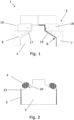
- the Fig. 1 shows the sectional view of a multi-part forming tool 1 according to the prior art, consisting of the multi-part die 2 and the patrix 3.
- the dashed line 16 which is only shown in the left half of the illustration, shows that the die is movable in the neck area. This allows the forming tool 1 to be moved into a closed and an open state.
- the process for closing and opening the forming tool 1 is as follows: close the neck area, as indicated by the dashed line 16, then bring the die 2 and the male die 2 closer together in a linear manner relative to one another, open the neck area and then move the die 2 and the male die 2 away in a linear manner relative to one another.
- the mobility of the die in the neck area is crucial so that the plastic tube 19 produced can be removed from the forming tool 1 without destroying areas of the plastic tube with undercuts.
- a cavity or hollow space 17 is formed between the parts of the forming tool 1, in which the tube head can be formed and connected to the tube body.
- the tube body In the open state of the forming tool 1 (not explicitly shown but indicated), the tube body can be slipped over the male mold 3 at the start of the process. After the process has ended, the tube can be demolded or removed from the mold in the open state of the forming tool 1.
- the female mold is cooled in a neck area 18 with the cooling device 6.
- the cooling devices can comprise contour-close cooling channels and can be supplied with a cooling fluid in order to dissipate heat from the respective parts of the forming tool. This accelerates the solidification of the preform. At the same time, however, a high starting temperature or initial temperature of the preform is required.
- FIG. 1 In the right half shows Figure 1 the cross-section of the tube 19 after processing.
- the cold tube body 5 and the hot preform 4 into the opened Shaping tool 1 is introduced.
- Shaping tool 1 is closed or converted into the closed state and in the process presses the plastic preform 4.
- the tube head of the tube is thus formed from the preform. Due to the high temperature of the preform, a welded connection is made with the tube body in the overlap area 8.
- the cooled die and patrix cool the tube so that the material solidifies and the tube can be removed from the shaping tool after it has been converted back into the open state.
- the disadvantage here is that the preform has to be introduced so hot that the temperature is sufficient to produce the welded connection before the cooled tool parts have dissipated the heat.
- the Fig. 2 shows, as already mentioned, how the tube body 5 and the preform 4 are introduced for processing, both in the prior art and in the invention.
- the tubular tube body 5 is pushed onto the cylindrical male mold 3 and the preform 4 is placed centered on the collar 20.
- the tubular tube body 5 (horizontally hatched) can be seen around the male mold 3 and the ring-shaped preform 4, also called a donut, rests on the collar 20 of the male mold 3.
- the preform 4 can be dispensed or applied, for example, from an extruder with an annular opening (not shown).
- the Fig. 3 shows a first embodiment of the shaping tool 1 of the device according to the invention with a cooling device 6, for example in the neck area 18 and the heating device 9 in the outer shoulder part 7.
- the heating device 9 is positioned so that the overlap area 8 is heated, which in the closed state of the shaping tool 1 with the axial end section (cf.: Figures 7b and 7c ) of the tube body (23) in axial direction A.
- the Heating device 9 which can also include contour-close heating channels, makes it easier to weld the preform to the tube body because, on the one hand, the edge section of the tube is preheated and, on the other hand, the preform cools less quickly in this area, so that the preform can be introduced into the tool at a lower temperature.
- thermal decomposition processes in the plastic of the preform in the extruder are greatly slowed down or even prevented, less energy has to be used for heating and cooling, and the cooling time for reaching a target temperature in the cooled areas is shortened, so that the cycle time can be reduced. This enables gentler and more energy-efficient processing.
- the Fig. 4 shows a second advantageous embodiment of the shaping tool 1.
- a cooling device 6 in the shoulder part 7 is implemented by means of the cooling fluid channels 11 and a heating device 9 in the shoulder part 7 is implemented by means of heating fluid channels 12.
- An insulating section 10 is located between the cooled, first section 21 and the heated, second section 22 of the shoulder part 7.
- the insulating section 10 can be formed, for example, by a separate thermally insulating material.
- the insulating section can be implemented by changing the material or structure of the material of the shoulder part 7. The advantage of this is that the thermal insulation means that the tempered sections do not influence each other or only influence each other minimally, which reduces the energy required for tempering and ensures a more uniform temperature in the sections.
- the Fig. 5 shows a third advantageous embodiment of the shaping tool 1.
- the heating device of the shoulder part 7 is designed as an electrical heating means 13.
- the embodiment with the electric heating means 13 can also be used with the embodiment of the Fig. 4 in which an insulating section and/or a cooling device is formed in the shoulder part 7 (cf. Figure 6 ).
- the electrical heating means may, for example, comprise heating resistors which generate and release heat when energised.
- the Fig. 6 shows a fourth advantageous embodiment of the shaping tool 1.
- the heating device is designed as an electrical heating means 13, wherein the heated, second section 22 of the tool is thermally decoupled from the cooled, first section 21 of the shoulder part 7 with the cooling fluid channels 11 by the insulating section 10.
- This embodiment thus combines the advantages of the two previous embodiments.
- the Fig. 7a shows a forming tool 1 during the process according to the invention.
- the Figure 7a The process step shown can follow the process step described in the Figure 2
- the shaping tool 1 is shown in the illustration of the Figure 7a into the closed state.
- the preform 4 is already partially pressed, while the tube body 5, in particular the axial end section 23, has not yet been formed or folded into the overlapping area 8.
- the geometrically complex head part (for example having an external thread) is produced by plastic deformation of the hot preform.
- heat transfer and preheating of the axial end section 23 can take place. With increasing proximity of the axial end section 23 and the shoulder part 7 and/or the heating device 13, the heat transfer is improved and increased.
- the Fig. 7b shows a forming tool 1 in the closed state during the method according to the invention.
- the preform 4 is completely formed and the axial end section 23 of the tube body 5 is folded into the overlap area 8.
- the first section 21 of the outer shoulder piece 7 is cooled by means of the cooling fluid channels 11, thus accelerating the solidification of the formed preform 8.
- the overlap area 8 is in Fig. 7c shown in an enlarged view.
- the Fig. 7c shows an enlarged section of the overlap area 8 in the forming tool.
- the electrical heating means 13 specifically heat this area, in which the axial end section 23 of the tube body is also arranged, so that the production of the welded connection between the preform formed into the tube head and the tube body is supported.
- the Figure 8 shows a pressing tool 14, which can be part of a second processing station of the device according to the invention.
- the forming tool 1 of the Figures 1 to 7c is advantageously part of a first processing station of the device.
- the pressing tool can, similar to the shaping tool, be transferred into an open and a closed state, whereby in the open state it is possible to insert and remove a tube and in the closed state it is possible to cool the tube, preferably the tube head.
- the post-pressing tool 14 can be cooled by means of cooling fluid which is guided through the contour-near cooling fluid channels 24.
- cooling the post-pressing tool 14 the cooling and solidification of the previously formed tube, in particular the tube head, is accelerated and controlled.
- pressure to the tube, in particular on the weld joint in the overlap area 8 it is ensured that the tube solidifies in the desired shape and the weld joint remains securely connected until it is sufficiently cold and thus solid.
Landscapes
- Engineering & Computer Science (AREA)
- Mechanical Engineering (AREA)
- Shaping Of Tube Ends By Bending Or Straightening (AREA)
Priority Applications (2)
| Application Number | Priority Date | Filing Date | Title |
|---|---|---|---|
| EP23190606.6A EP4506145A1 (fr) | 2023-08-09 | 2023-08-09 | Dispositif et procédé de formation d'une tête de tube par compression d'une préforme et de liaison de la tête de tube à un corps de tube pour la fabrication d'un tube d'emballage |
| PCT/EP2024/071726 WO2025031911A1 (fr) | 2023-08-09 | 2024-07-31 | Appareil et procédé de formation d'une tête de tube par compression d'une préforme et raccordement de la tête de tube à un corps de tube afin de produire un tube d'emballage |
Applications Claiming Priority (1)
| Application Number | Priority Date | Filing Date | Title |
|---|---|---|---|
| EP23190606.6A EP4506145A1 (fr) | 2023-08-09 | 2023-08-09 | Dispositif et procédé de formation d'une tête de tube par compression d'une préforme et de liaison de la tête de tube à un corps de tube pour la fabrication d'un tube d'emballage |
Publications (1)
| Publication Number | Publication Date |
|---|---|
| EP4506145A1 true EP4506145A1 (fr) | 2025-02-12 |
Family
ID=87567545
Family Applications (1)
| Application Number | Title | Priority Date | Filing Date |
|---|---|---|---|
| EP23190606.6A Pending EP4506145A1 (fr) | 2023-08-09 | 2023-08-09 | Dispositif et procédé de formation d'une tête de tube par compression d'une préforme et de liaison de la tête de tube à un corps de tube pour la fabrication d'un tube d'emballage |
Country Status (2)
| Country | Link |
|---|---|
| EP (1) | EP4506145A1 (fr) |
| WO (1) | WO2025031911A1 (fr) |
Citations (3)
| Publication number | Priority date | Publication date | Assignee | Title |
|---|---|---|---|---|
| AT249358B (de) * | 1959-11-18 | 1966-09-26 | Valer Flax | Verfahren und Vorrichtung zum Befestigen eines Tubenkopfstückes an einem rohrförmigen Tubenkörper aus thermoplastischem Kunststoff |
| DE2023652A1 (en) * | 1969-06-16 | 1971-01-07 | C F. Spiess & Sohn, 6719 Kleinkarl bach | Plastic tubes production |
| US5690764A (en) * | 1995-02-13 | 1997-11-25 | The Procter & Gamble Company | Collapsible tube package and method of construction |
-
2023
- 2023-08-09 EP EP23190606.6A patent/EP4506145A1/fr active Pending
-
2024
- 2024-07-31 WO PCT/EP2024/071726 patent/WO2025031911A1/fr active Pending
Patent Citations (3)
| Publication number | Priority date | Publication date | Assignee | Title |
|---|---|---|---|---|
| AT249358B (de) * | 1959-11-18 | 1966-09-26 | Valer Flax | Verfahren und Vorrichtung zum Befestigen eines Tubenkopfstückes an einem rohrförmigen Tubenkörper aus thermoplastischem Kunststoff |
| DE2023652A1 (en) * | 1969-06-16 | 1971-01-07 | C F. Spiess & Sohn, 6719 Kleinkarl bach | Plastic tubes production |
| US5690764A (en) * | 1995-02-13 | 1997-11-25 | The Procter & Gamble Company | Collapsible tube package and method of construction |
Also Published As
| Publication number | Publication date |
|---|---|
| WO2025031911A1 (fr) | 2025-02-13 |
Similar Documents
| Publication | Publication Date | Title |
|---|---|---|
| DE10038158B4 (de) | Verfahren und Vorrichtung zum Verbinden von Gegenständen mittels plastisch verformbarer Verbindungskörper | |
| EP3134248B1 (fr) | Dispositif et procédé de formage à chaud d'ébauches de tuyau optimisé en termes de cycle et de complexité | |
| DE102012004613A1 (de) | Verfahren und Vorrichtung zur Herstellung einer optimierten Bodenkontur von Preformen | |
| DE19928873B4 (de) | Verfahren und Vorrichtung zum Innendruckformen eines hohlen metallischen Werkstücks aus Aluminium oder einer Aluminiumlegierung | |
| EP0280204B1 (fr) | Procédé et appareil pour le formage d'un flanc à un corps creux en matière thermoplastique | |
| WO2014187852A9 (fr) | Procédé et dispositif de fabrication d'un composant façonné | |
| EP2332715A2 (fr) | Machine de formage par soufflage doté d'un dispositif de refroidissement | |
| EP3186063B1 (fr) | Système de traitement ultérieur de préformes fabriquées par moulage par injection | |
| DE2543640B2 (de) | Verfahren und Vorrichtung zum Herstellen eines Vorformlings für das Blasformen eines Hohlkörpers | |
| EP2758224B1 (fr) | Dispositif et procédé pour la production, à optimisation de processus et de cycle, de corps creux à partir d'une ébauche tubulaire | |
| EP4506145A1 (fr) | Dispositif et procédé de formation d'une tête de tube par compression d'une préforme et de liaison de la tête de tube à un corps de tube pour la fabrication d'un tube d'emballage | |
| DE102012014013B4 (de) | Verfahren und Vorrichtung zur Herstellung eines Kunststoffteils, insbesondere eines Kunststoffteils für ein Automobil, in einem Spritzgussverfahren | |
| AT515969B1 (de) | Vorrichtung und Verfahren zur Erstellung zumindest eines metallischen Bauteils | |
| WO2007063063A1 (fr) | Procede de post-traitement et dispositif approprie | |
| DE102025105264B3 (de) | Spritzgießvorrichtung mit Mikrowellen-Vorwärmung und nachgeschalteter Angussverteilung und Spritzgießverfahren mit Mikrowellen-Vorwärmung | |
| DE2817099A1 (de) | Vorrichtung zum herstellen eines aus einem thermoplastischen kunststoff bestehenden rohrfoermigen koerpers | |
| DE102006000949B4 (de) | Spritzgussvorrichtung bzw. Spritzgussverfahren zum Herstellen eines Spritzguss-Formteils mit einem seitlich von einer Formteilwandung abstehenden Rohr | |
| DE60309696T2 (de) | Verfahren und system zur herstellung eines zweigs in einem polymerrohr unter verwendung erwärmter flüssigkeit zur plastifizierung eines rohrwandabschnitts, der zur bildung des zweigs nach aussen verschoben werden soll | |
| EP3024952B1 (fr) | Procédé et dispositif permettant le durcissement partiel de demi-produits | |
| EP1900494A1 (fr) | Procédé de fabrication de composants en forme de tiges | |
| WO2024074439A1 (fr) | Dispositif et procédé de fabrication d'un récipient, rempli d'un matériau de remplissage liquide, à partir d'une préforme thermiquement conditionnée | |
| EP2746019B1 (fr) | Procédé et dispositif de fabrication de pièces à partir de produits semi-finis en fibres | |
| DE2262871C3 (de) | Verfahren und Vorrichtung zum Herstellen eines zweischichtigen Hohlkörpers nach dem Spritzblasverfahren | |
| AT517240B1 (de) | Barrel für eine Thixomoldingvorrichtung | |
| EP4568824A1 (fr) | Dispositif et procédé de fabrication d'un récipient, rempli d'un matériau de remplissage liquide, à partir d'une préforme thermiquement conditionnée |
Legal Events
| Date | Code | Title | Description |
|---|---|---|---|
| PUAI | Public reference made under article 153(3) epc to a published international application that has entered the european phase |
Free format text: ORIGINAL CODE: 0009012 |
|
| STAA | Information on the status of an ep patent application or granted ep patent |
Free format text: STATUS: THE APPLICATION HAS BEEN PUBLISHED |
|
| AK | Designated contracting states |
Kind code of ref document: A1 Designated state(s): AL AT BE BG CH CY CZ DE DK EE ES FI FR GB GR HR HU IE IS IT LI LT LU LV MC ME MK MT NL NO PL PT RO RS SE SI SK SM TR |
|
| STAA | Information on the status of an ep patent application or granted ep patent |
Free format text: STATUS: REQUEST FOR EXAMINATION WAS MADE |
|
| 17P | Request for examination filed |
Effective date: 20250612 |