EP4513984A1 - Datenübertragungsverfahren und zugehörige vorrichtung - Google Patents
Datenübertragungsverfahren und zugehörige vorrichtung Download PDFInfo
- Publication number
- EP4513984A1 EP4513984A1 EP23810720.5A EP23810720A EP4513984A1 EP 4513984 A1 EP4513984 A1 EP 4513984A1 EP 23810720 A EP23810720 A EP 23810720A EP 4513984 A1 EP4513984 A1 EP 4513984A1
- Authority
- EP
- European Patent Office
- Prior art keywords
- data packet
- user equipment
- downlink data
- rrc
- network device
- Prior art date
- Legal status (The legal status is an assumption and is not a legal conclusion. Google has not performed a legal analysis and makes no representation as to the accuracy of the status listed.)
- Pending
Links
Images


Classifications
-
- H—ELECTRICITY
- H04—ELECTRIC COMMUNICATION TECHNIQUE
- H04W—WIRELESS COMMUNICATION NETWORKS
- H04W68/00—User notification, e.g. alerting and paging, for incoming communication, change of service or the like
-
- H—ELECTRICITY
- H04—ELECTRIC COMMUNICATION TECHNIQUE
- H04W—WIRELESS COMMUNICATION NETWORKS
- H04W68/00—User notification, e.g. alerting and paging, for incoming communication, change of service or the like
- H04W68/02—Arrangements for increasing efficiency of notification or paging channel
-
- H—ELECTRICITY
- H04—ELECTRIC COMMUNICATION TECHNIQUE
- H04W—WIRELESS COMMUNICATION NETWORKS
- H04W76/00—Connection management
- H04W76/20—Manipulation of established connections
- H04W76/27—Transitions between radio resource control [RRC] states
-
- H—ELECTRICITY
- H04—ELECTRIC COMMUNICATION TECHNIQUE
- H04W—WIRELESS COMMUNICATION NETWORKS
- H04W52/00—Power management, e.g. Transmission Power Control [TPC] or power classes
- H04W52/02—Power saving arrangements
- H04W52/0209—Power saving arrangements in terminal devices
- H04W52/0212—Power saving arrangements in terminal devices managed by the network, e.g. network or access point is leader and terminal is follower
-
- H—ELECTRICITY
- H04—ELECTRIC COMMUNICATION TECHNIQUE
- H04W—WIRELESS COMMUNICATION NETWORKS
- H04W76/00—Connection management
- H04W76/20—Manipulation of established connections
- H04W76/25—Maintenance of established connections
-
- H—ELECTRICITY
- H04—ELECTRIC COMMUNICATION TECHNIQUE
- H04W—WIRELESS COMMUNICATION NETWORKS
- H04W88/00—Devices specially adapted for wireless communication networks, e.g. terminals, base stations or access point devices
- H04W88/02—Terminal devices
-
- H—ELECTRICITY
- H04—ELECTRIC COMMUNICATION TECHNIQUE
- H04W—WIRELESS COMMUNICATION NETWORKS
- H04W88/00—Devices specially adapted for wireless communication networks, e.g. terminals, base stations or access point devices
- H04W88/08—Access point devices
Definitions
- This application relates to the field of communication technologies, and specifically, to a data transmission method and a related device.
- a radio resource control (Radio Resource Control, RRC) state is introduced: an RRC inactive (Inactive) state.
- RRC Radio Resource Control
- a gNB When user equipment (User Equipment, UE) is in the RRC inactive state, if a gNB sends a downlink data packet or signaling to the user equipment, the user equipment needs to migrate from the RRC inactive state to an RRC connected state to receive the downlink data packet or signaling. In addition, after the user equipment successfully receives the data sent by the gNB, the user equipment subsequently switches from the RRC connected state to the RRC inactive state. Because the gNB sends the downlink data packet or signaling to the user equipment relatively frequently, the user equipment needs to frequently migrate between the RRC inactive state and the RRC connected state, and consequently, signaling overheads are relatively high, which increases power consumption of the user equipment.
- the user equipment remains in the RRC connected state after the user equipment successfully receives the data sent by the gNB, if a service frequency is not high, for example, a period in which the gNB sends the downlink data packet to the user equipment is very long, the user remains in the RRC connected state for a long time, resulting in excessively large power consumption of the user equipment.
- a first aspect of this application provides a data transmission method, applied to a network device.
- the network device may be a base station device, and the method includes: receiving a first downlink data packet to be sent to user equipment; if the first downlink data packet meets a preset transmission scenario, sending an enhanced paging message to the user equipment, where the enhanced paging message carries a mobile-terminated small data transmission indication, so that the user equipment activates a corresponding target bearer based on the mobile-terminated small data transmission indication in the enhanced paging message; and receiving a paging response message sent by the user equipment, and sending the first downlink data packet to the user equipment, so that the user equipment in a radio resource control RRC inactive state receives the first downlink data packet based on the target bearer.
- the network device sends the downlink data packet to the user equipment after receiving a response message from the user equipment, and the user equipment receives the downlink data packet based on the target bearer. In this way, the user equipment can receive the downlink data packet in the RRC inactive state.
- the user equipment may receive the new downlink data packet based on the activated target bearer. In this way, the downlink data packet is received in the RRC inactive state, to reduce state switching of the user equipment and reduce a loss of the user equipment.
- the enhanced paging message further carries a trigger indication and a receive indication, where the trigger indication is used to indicate the user equipment not to send an RRC resume request message to the network device when receiving the enhanced paging message, and the receive indication is used to indicate the user equipment to receive, in the RRC inactive state, the first downlink data packet sent by the network device.
- the network device adds the trigger indication and the receive indication to the enhanced paging message, to indicate the user equipment to directly receive a downlink data packet in the RRC inactive state and not to trigger the RRC resume request message after receiving the enhanced paging message, thereby preventing the user equipment from entering an RRC connected state to consume user signaling.
- the network device sends the first downlink data packet to the user equipment by using a downlink media access control layer protocol data unit, where the downlink media access control layer protocol data unit carries a media access control layer control unit, and the media access control layer control unit is configured to indicate the user equipment not to send the RRC resume request message to the network device when receiving the enhanced paging message, and receive, in the RRC inactive state, the first downlink data packet sent by the network device.
- the network device newly adds the media access control layer control unit to the downlink media access control layer protocol data unit, to indicate the user equipment to directly receive a downlink data packet in the RRC inactive state and not to trigger the RRC resume request message after receiving the enhanced paging message, thereby preventing the user equipment from entering an RRC connected state to consume user signaling.
- a method for determining that the first downlink data packet meets the preset transmission scenario includes: determining that the first downlink data packet is a small data packet; and ⁇ or the first downlink data packet carries transmission indication information, and the transmission indication information is used to indicate that the first downlink data packet meets the preset transmission scenario. In this way, when a downlink data packet meets the foregoing condition, the downlink data packet meets the preset transmission scenario, and the network device can be triggered to send the enhanced paging message.
- the enhanced paging message further carries a bearer identity, so that the user equipment activates the corresponding target bearer based on the bearer identity and the mobile-terminated small data transmission indication. In this way, the user equipment activates the corresponding target bearer based on the bearer identity.
- the user equipment activates, based on the mobile-terminated small data transmission indication, all bearers configured with small data transmission.
- the method further includes: if a received second downlink data packet to be sent to the user equipment does not meet the preset transmission scenario, or/and a received uplink data packet sent by the user equipment does not meet the preset transmission scenario, sending an RRC resume message to the user equipment, so that the user equipment migrates from the RRC inactive state to an RRC connected state, where time for receiving the first downlink data packet by the network device is earlier than time for receiving the second downlink data packet and the uplink data packet by the network device.
- the user equipment migrates from the RRC inactive state to the RRC connected state, so that the user equipment can successfully receive the downlink data packet or upload the uplink data packet.
- the method when sending the first downlink data packet to the user equipment, the method further includes: determining that the first downlink data packet is a single data packet; or starting, by the network device, a small data timer when sending the first downlink data packet to the user equipment, and if the small data timer expires and no new downlink data packet to be sent to the user equipment is received, sending an RRC release message to the user equipment.
- the RRC release message is sent to the user equipment to release the target bearer of the user equipment, thereby reducing power consumption of the user equipment.
- a second aspect of this application provides a data transmission method, applied to user equipment.
- the method includes: receiving an enhanced paging message sent by a network device, where the enhanced paging message carries a mobile-terminated small data transmission indication; activating a corresponding target bearer based on the mobile-terminated small data transmission indication, so that the user equipment receives, in an RRC inactive state, a downlink data packet sent by the network device; sending a paging response message to the network device; and receiving, based on the target bearer, a first downlink data packet sent by the network device.
- the enhanced paging message further carries a trigger indication and a receive indication, where the trigger indication is used to indicate the user equipment not to send an RRC resume request message to the network device when receiving the enhanced paging message, and the receive indication is used to indicate the user equipment to receive, in the RRC inactive state, the first downlink data packet sent by the network device.
- the network device sends the first downlink data packet to the user equipment by using a downlink media access control layer protocol data unit, where the downlink media access control layer protocol data unit further carries a media access control layer control unit, and the media access control layer control unit is configured to indicate the user equipment not to send the RRC resume request message to the network device when receiving the enhanced paging message, and receive, in the RRC inactive state, the first downlink data packet sent by the network device.
- the RRC inactive state includes a first RRC inactive state and a second RRC inactive state
- the method further includes: starting a small data packet timer; and if the small data packet timer expires, deactivating the target bearer and migrating the user equipment from the first RRC inactive state to the second RRC inactive state. In this way, the user equipment starts the small data transmission timer after activating the target bearer. After the small data transmission timer expires, the user equipment switches between sub-states of the RRC inactive state. Because the switching does not require signaling interaction with the network device, signaling overheads of the user equipment are reduced.
- the method further includes: if a received second downlink data packet does not meet a preset receiving scenario, or/and an uplink data packet sent to the network device does not meet the preset receiving scenario, sending an RRC resume request message to the network device, so that the user equipment migrates from the RRC inactive state to an RRC connected state, where time for receiving the first downlink data packet by the user equipment is earlier than time for receiving the second downlink data packet and sending the uplink data packet by the user equipment.
- that the received second downlink data packet does not meet the preset receiving scenario, or/and that the uplink data packet sent to the network device does not meet the preset receiving scenario includes: the received second downlink data packet sent by the network device is a non-small data packet, or/and the uplink data packet sent to the network device is a non-small data packet, or/and a quantity of second downlink data packets received from the network device is greater than a quantity threshold, or/and a quantity of uplink data packets sent to the network device is greater than a quantity threshold, or/and a size of the second downlink data packet received from the network device is greater than a size threshold, or/and a size of the uplink data packet sent to the network device is greater than a size threshold.
- the enhanced paging message further carries a bearer identity, so that the user equipment activates the corresponding target bearer based on the bearer identity.
- an embodiment of this application provides a network device, including:
- an embodiment of this application provides user equipment, including:
- an embodiment of this application provides a computer-readable storage medium.
- the computer-readable storage medium includes computer instructions.
- the computer instructions When the computer instructions are run on an electronic device, the electronic device is enabled to perform the method according to any one of the implementations of the first aspect.
- an embodiment of this application provides a computer-readable storage medium.
- the computer-readable storage medium includes computer instructions.
- the computer instructions When the computer instructions are run on an electronic device, the electronic device is enabled to perform the method according to any one of the implementations of the second aspect.
- the method in the second aspect, the network device in the third aspect, the user equipment in the fourth aspect, the computer-readable storage medium in the fifth aspect, and the computer-readable storage medium in the sixth aspect that are provided above all correspond to the method in the first aspect. Therefore, for beneficial effects that can be achieved by the method, the network device, the user equipment, and the computer-readable storage media, refer to the beneficial effects in the corresponding method provided above. Details are not described herein again.
- User Equipment User Equipment
- the user equipment may also be referred to as a mobile terminal (Mobile Terminal), mobile user equipment, or the like, and may communicate with one or more core networks through a radio access network (Radio Access Network, RAN).
- Mobile Terminal Mobile Terminal
- RAN Radio Access Network
- the network device is a device that is deployed in a radio access network and that provides a wireless communication function for user equipment.
- the network device may include a base station, and the base station may include a macro base station, a micro base station, a relay station, an access point base station controller, a transmission and reception point (Transmission and Reception Point, TRP), and the like.
- the base station has different specific names.
- the base station in a long term evolution (Long Term Evolution, LTE) network, the base station is referred to as an evolved NodeB (Evolved NodeB, eNB), and in a subsequent evolved system, the base station may also be referred to as a new radio NodeB (New Radio NodeB, gNB).
- LTE Long Term Evolution
- eNB evolved NodeB
- New Radio NodeB New Radio NodeB
- the gNB may serve as a serving gNB (Serving gNB) and/or an anchor gNB (Anchor gNB).
- the serving gNB is a gNB that currently serves the user equipment
- the anchor gNB is a gNB that serves the user equipment last time.
- Radio access network Radio Access Network, RAN
- RAN Radio Access Network
- RNA Radio Access Network based notification area
- the radio access network based notification area is also referred to as a radio access network notification area (RNA), and may include one or more cells. If the RNA includes a plurality of cells, the plurality of cells may be cells controlled by one or more base stations (for example, eNB and/or gNB).
- a radio access network notification area may include one or more cells. If the RNA includes a plurality of cells, the plurality of cells may be cells controlled by one or more base stations (for example, eNB and/or gNB).
- Core network Core Network, CN
- User equipment performs data transmission with the core network by using a network device, for example, performs data transmission with an access and mobility management function (Access and Mobility Management Function, AMF) or a user plane function (User Plane Function, UPF) of the core network.
- AMF Access and Mobility Management Function
- UPF User Plane Function
- Radio resource control Radio Resource Control, RRC
- network functions and entities mainly include: user equipment (UE), an access network (access network, AN) or a radio access network (RAN), a user plane function (UPF), a data network (data network, DN), an access management function (AMF), a session management function (session management function, SMF), an authentication server function (authentication server function, AUSF), a policy control function (policy control function, PCF), an application function (application function, AF), a network slice selection function (network slice selection function, NSSF), unified data management (unified data management, UDM) function, a network exposure function (network exposure function, NEF), and a network repository function (network repository function, NRF).
- UE user equipment
- access network access network
- RAN radio access network
- UPF user plane function
- AMF access management function
- SMF session management function
- policy control function policy control function
- PCF policy control function
- application function application function
- AF network slice selection function
- NSSF network slice selection function
- UDM network
- a network function can be used as a network element running on dedicated hardware, or a software instance running on dedicated hardware, or a virtual function instantiated on an appropriate platform, for example, implemented on a cloud infrastructure.
- the AN/RAN may include various forms of network devices.
- the AN/RAN is mainly responsible for functions such as radio resource management on an air interface side, uplink and downlink data classification, quality of service (quality of service, QoS) management, data compression and encryption, and completion of signaling processing with a control plane network element or completion of data forwarding with a user plane function network element.
- QoS quality of service
- a specific form and structure of the AN/RAN are not limited in the embodiments of this application.
- the UPF is mainly responsible for packet routing and forwarding, QoS processing of user plane data, collection of statistics about charging information, and the like.
- a transmission resource and a scheduling function in the UPF that are for providing a service to UE are managed and controlled by the SMF.
- the DN is a network used for transmitting data.
- the DN may be an operator service network, an internet access network, or a third-party service network.
- user equipment In a 5G network, user equipment has three RRC states: an RRC connected state, an RRC idle state, and an RRC inactive state.
- the three RRC states may be switched to each other.
- conversion between the three RRC states may also be referred to as "state switching" or "state migration”.
- the RRC connected (Connected) state may also be referred to as a connected state for short.
- the "connected state” and the “RRC connected state” are same concepts.
- the user equipment When the user equipment is in the connected state, the user equipment establishes an RRC connection to a network, and may perform data transmission.
- the RRC idle (Idle) state or may be referred to as an idle state for short.
- the "idle state” and the "RRC idle state” are same concepts.
- the user equipment When the user equipment is in the idle state, the user equipment does not establish an RRC connection to a network, and a gNB does not store context (Context) of the user equipment. If the user equipment needs to enter the RRC connected state from the RRC idle state, the user equipment needs to initiate an RRC connection establishment process.
- the RRC inactive (Inactive) state may also be referred to as an inactive state for short.
- the "inactive state” and the "RRC inactive state” are same concepts.
- the anchor gNB releases the RRC connection, but the anchor gNB stores the context of the user equipment. If the user equipment needs to enter the RRC connected state again from the RRC inactive state, the user equipment needs to initiate an RRC connection resume process at a serving gNB, which is referred to as an RRC connection reestablishment process. Because the user equipment may be moving, the serving gNB and the anchor gNB may be a same gNB, or may be different gNBs.
- a data packet whose data amount is less than a preset data amount threshold may be referred to as a small data packet.
- user equipment in an idle state or an inactive state needs to first perform transmission of a plurality of pieces of control signaling with a base station before entering a connected state, and then can perform data or signaling transmission with the base station.
- MTC Machine Type Communication
- the user equipment frequently sends some small data packets to the base station.
- the user equipment in the idle state or the inactive state needs to frequently switch to the connected state, causing a large quantity of signaling overheads, and increasing power consumption of the base station.
- the small data transmission manner means that after determining that a to-be-transmitted data packet is a small data packet, the user equipment integrates the small data packet into some control signaling, and then transmits the small data packet to the base station by using the control signaling. Alternatively, the user equipment transmits the small data packet to the base station by using context stored in the user equipment.
- the small data transmission manner may include an early data transmission (Early Data Transmission, EDT) manner, a two-step random access manner, a pre-configured uplink resource (Pre-Configured Uplink Resource, PUR) manner, and the like.
- Mobile terminated is a mobile message that is routed from a core network device (such as an AMF) or a network device (such as a base station) and that is sent to user equipment. Mobile terminated also refers to a voice call terminated on the user equipment from another mobile user, a public switched telephone network (Public Switch Telephone Network, PSTN), or another network.
- a core network device such as an AMF
- a network device such as a base station
- PSTN Public Switch Telephone Network
- terminated means that transfer of a message is terminated on the user equipment.
- the term also describes communication between a short message service center (Short Message Service Center, SMSC) and the user equipment, and between a mobile switching center (Mobile Switching Center, MSC) and the user equipment.
- SMSC Short Message Service Center
- MSC Mobile Switching Center
- MT-SDT refers to a manner of small data transmission terminated on user equipment, which is also referred to as mobile-terminated small data transmission.
- the user equipment may not switch to an RRC connected state to reduce signaling overheads and UE power consumption, and allows fast transmission of a small data packet (for example, a small data packet used for positioning) to reduce a delay.
- MT-SDT corresponds to mobile originating-small data transmission (Mobile Originating-Small Data Transmission, MO-SDT), which is also referred to as mobile originating-small data transmission.
- MO-SDT refers to a manner of small data transmission initiated by user equipment. When sending uplink data and/or signaling to a network device in the MO-SDT manner, the user equipment may transmit a small data packet in an RRC inactive state, thereby reducing signaling overheads and UE power consumption.
- UE Context user equipment context
- the user equipment context is used to store device information of the user equipment, for example, a mobile number, a device number, an IP address, and a quality of service (Quality of Service, QoS) parameter.
- the user equipment context is used to maintain a communication connection to the user equipment and service processing for the user equipment in the communication process.
- the "user equipment context (UE Context)” is referred to as “context (context)” for short.
- Radio bearer (Radio Bearer, RB)
- the radio bearer includes a data radio bearer (Data Radio Bearer, DRB) and a signaling radio bearer (Signaling Radio Bearer, SRB), a DRB type includes a DRB1, a DRB2, and the like, and an SRB type includes an SRB1, an SRB2, and the like.
- DRB Data Radio Bearer
- SRB Signaling Radio Bearer
- Radio access network-based paging (RAN-based Paging)
- the radio access network-based paging refers to paging (Paging) initiated by a network device in a radio access network notification area (RNA), to determine a cell in which user equipment is located.
- Paging paging
- RNA radio access network notification area
- the network device When receiving downlink data/signaling from a core network, the network device triggers a radio access network paging (RAN Paging) message.
- RAN-based Paging "RAN Paging”
- RAN Paging radio access network paging
- the Xn interface refers to an interface for data transmission between two gNBs, for example, data transmission is performed between a serving gNB and an anchor gNB by using the Xn interface.
- the Xn interface may include but is not limited to a user plane interface Xn-U, a control plane interface Xn-C, and the like.
- the user plane interface Xn-U mainly provides a data forwarding function and a traffic control function.
- the control plane interface Xn-C mainly provides functions such as Xn interface management, UE mobility management, and dual connectivity implementation.
- the NG interface refers to an interface for data transmission between a radio access network and a core network.
- the NG interface may include but is not limited to a user plane interface NG-U, a control plane interface NG-C, and the like.
- the user plane interface NG-U is an interface between the radio access network and a user plane function (UPF) of the core network.
- the control plane interface NG-C is an interface between the radio access network and a control plane function (AMF) of the core network.
- UPF user plane function
- AMF control plane function
- UE user equipment
- Anchor gNB an anchor gNB
- UE Context user equipment context
- the user equipment context is the same as user equipment context in the RRC connected state or is a part of the user equipment context in the RRC connected state.
- RAN Radio Access Network
- RNA Radio Notification Area
- Scenario 1 The user equipment enters a serving range of a serving gNB (Serving gNB), and the user equipment receives a broadcast signal from the serving gNB, and performs data transmission with a core network by using the serving gNB.
- the anchor gNB receives a downlink data packet/signaling from the core network
- the anchor gNB triggers a radio access network paging (RAN Paging) message.
- RAN Paging radio access network paging
- the anchor gNB sends the paging message to the serving gNB, and the serving gNB continues to broadcast the paging message.
- RAN Paging radio access network paging
- the serving gNB may determine that the user equipment is currently in the serving range of the serving gNB. Therefore, the anchor gNB needs to forward the downlink data packet/signaling to the user equipment by using the serving gNB.
- Scenario 2 The user equipment is still in the serving range of the anchor gNB, and the user equipment continues to receive the broadcast signal from the anchor gNB, and performs data transmission with the core network by using the anchor gNB.
- the anchor gNB and the serving gNB are a same gNB.
- the anchor gNB receives a downlink data packet/signaling from the core network
- the anchor gNB triggers a radio access network paging (RAN Paging) message.
- RAN Paging radio access network paging
- the anchor gNB may determine that the user equipment is currently in the serving range of the anchor gNB. In this case, the anchor gNB may directly send the downlink data packet/signaling to the user equipment.
- Scenario 1 a difference between Scenario 1 and Scenario 2 lies in the following:
- the anchor gNB needs to forward the downlink data packet/signaling by using the serving gNB when sending the downlink data packet/signaling to the user equipment.
- the anchor gNB and the serving gNB are a same gNB, and therefore, the anchor gNB may directly send the downlink data packet/signaling to the user equipment.
- a 5G new radio (New Radio, NR) network includes a connected state and an idle state.
- an RRC inactive state is introduced into the 5G NR network.
- a gNB sends, to user equipment (UE) in the connected state, an RRC release (Release) message that carries a suspend (Suspend) configuration to indicate the UE to enter the RRC inactive state.
- RRC release Release
- context Context information of the UE is suspended on both a terminal side and a gNB side.
- the UE triggers an RRC resume request (Resume Request) procedure, so that the UE switches from the RRC inactive state to the RRC connected state and then can send the data/signaling.
- FIG. 1 is a schematic diagram in which when UE needs to send data and/or signaling to a network side, the UE moves from an RRC inactive state to an RRC connected state.
- the user equipment when the UE is in the RRC inactive state, if the UE needs to send data/signaling to a network device, the user equipment (UE) sends an RRC resume request (RRC Resume Request) message to a serving gNB, to request to resume to the RRC connected state (refer to S101).
- RRC Resume Request RRC resume request
- the serving gNB sends a retrieve UE context request (Retrieve UE Context Request) message to an anchor gNB to obtain user context information (UE Context) (refer to S102).
- UE Context user context information
- the anchor gNB In response to the retrieve user context request message, the anchor gNB sends a retrieve user context response (Retrieve UE Context Response) message to the serving gNB, where the user context response message carries the user context information (refer to S103).
- retrieve user context response Retrieve UE Context Response
- the serving gNB After obtaining the context information, the serving gNB sends an RRC resume (RRC Resume) message to the user equipment, to indicate the user equipment to resume to the RRC connected state (refer to S104).
- RRC Resume RRC resume
- the user equipment After resuming from the RRC inactive state to the RRC connected state, the user equipment sends an RRC resume complete (RRC Resume Complete) message to the serving gNB, to notify the serving gNB that the user equipment has resumed to the RRC connected state (refer to S105).
- RRC Resume Complete RRC Resume Complete
- the serving gNB sends an Xn-U address indication (Xn-U Address Indication) message to the anchor gNB, where the Xn-U address indication message carries a data forwarding address (refer to S106).
- the serving gNB provides the data forwarding address to the anchor gNB, to prevent a downlink data packet buffered in the anchor gNB from being lost in a data transmission process.
- the serving gNB sends a path switch request (Path Switch Request) message to a core network (such as an AMF), to request to switch an endpoint of a downlink of an NG interface transport bearer to a new endpoint (refer to S107).
- a core network such as an AMF
- the core network In response to the path switch request, the core network sends a path switch response (Path Switch Response) message to the serving gNB (refer to S108), to notify the serving gNB that the downlink of the NG interface transport bearer has been switched to the new endpoint (refer to S108).
- a path switch response Path Switch Response
- the serving gNB sends a user equipment context release (UE Context Release) message to the anchor gNB, to indicate the anchor gNB to release the context information buffered in the anchor gNB (refer to S109).
- UE Context Release user equipment context release
- FIG. 2 is another schematic diagram in which UE migrating from an RRC inactive state to an RRC connected state when data and/or signaling need/needs to be sent.
- an anchor gNB when the UE is in the RRC inactive state, if an anchor gNB receives a downlink data packet/signaling from a core network (refer to S201), the anchor gNB pages the user equipment in a radio access network-based notification area (RAN-based Notification Area, RNA), and may directly send a paging (Paging) message to the user equipment, or may forward the paging message to the user equipment by using a serving gNB.
- RAN-based Notification Area RNA
- the anchor gNB sends a radio access network paging (RAN Paging) message to the serving gNB, to indicate the serving gNB to page the user equipment in the radio access network-based notification area (RNA) (refer to S202-S203).
- the serving gNB pages the user equipment (Paging UE) over an air interface by using an inactive radio network temporary identity (Inactive Radio Network Temporary Identity, I-RNTI) (refer to S204).
- I-RNTI Inactive Radio Network Temporary Identity
- the user equipment triggers an RRC resume request procedure (refer to S101-S109 in FIG. 1 ) to resume from the RRC inactive state (Resume from RRC Inactive State) to the RRC connected state, and then receives the downlink data packet/signaling.
- the serving gNB After the user equipment successfully receives the downlink data packet/signaling, the serving gNB sends a context release message to the user equipment, and the user equipment migrates from the RRC connected state to the RRC inactive state again. As shown in FIG. 1 and FIG. 2 , if data/signaling is transmitted frequently, the user equipment frequently performs state migration, causing an excessively large proportion of signaling overheads.
- this application provides a data transmission method, to support a mobile terminated-small data transmission (Mobile Terminated-Small Data Transmission, MT-SDT) function, and indicate user equipment to receive a downlink data packet in an RRC inactive state, thereby reducing signaling overheads caused by state migration of the user equipment, reducing an amount of signaling between interfaces of a serving gNB and an anchor gNB, and reducing a service delay.
- MT-SDT Mobile Terminated-Small Data Transmission
- FIG. 2 is a flowchart of a data transmission method according to an implementation of this application.
- the data transmission method may include the following steps: S301: An anchor gNB obtains a downlink data packet from a core network.
- the downlink data packet may be downlink data (Downlink Data) or downlink signaling (Downlink Signaling).
- the downlink data packet may carry assistance information, radio bearer (Radio Bearer, RB) information, a data packet size, and the like.
- the assistance information is used to indicate data that needs to be transmitted.
- the assistance information may include subscription data, a capability, data transmission statistics information, a data/signaling service feature, and indication information of the UE that are related to SDT.
- the data service feature may include a frequency of a single data packet/multi-data packet, duration of a session, and a data amount in a session.
- the signaling service feature may include a signaling frequency and a signaling data packet size.
- the downlink data packet may further carry indication information to indicate triggering of MT-SDT data transmission.
- the anchor gNB sends an enhanced paging message to the user equipment.
- the downlink data packet meets the preset transmission scenario, it indicates that the data can be transmitted to the user equipment by using an MT-SDT method.
- the downlink data packet sent by the core network carries the indication information.
- the anchor gNB may determine, based on the indication information, whether MT-SDT data transmission can be triggered for the downlink data, that is, whether the data can be transmitted to the user equipment by using the MT-SDT method. If yes, it is determined that the downlink data packet meets the preset transmission scenario; or if no, it is determined that the downlink data packet does not meet the preset transmission scenario, and the user equipment needs to be indicated to establish a connection to the anchor gNB, so that the user equipment enters a connected state to receive the downlink data packet.
- the downlink data packet sent by the core network carries the assistance information.
- the anchor gNB may determine, based on the assistance information, whether MT-SDT data transmission can be triggered for the downlink data, that is, whether the data can be transmitted to the user equipment by using the MT-SDT method. If yes, it is determined that the downlink data packet meets the preset transmission scenario.
- the anchor gNB may determine that the downlink data packet meets the preset transmission scenario.
- the anchor gNB stores an MT-SDT list, and the MT-SDT list records at least one downlink data packet.
- the anchor gNB determines whether the received downlink data packet delivered by the core network is recorded in the MT-SDT list, and if yes, determines that the downlink data packet meets the preset transmission scenario.
- S303 The user equipment receives the enhanced paging message, and activates a corresponding target bearer, so that the user equipment is in the RRC inactive state.
- the enhanced paging message carries an MT-SDT indication parameter
- the user equipment activates, based on the MT-SDT indication parameter, a bearer configured with a small data transmission capability.
- the enhanced paging message further carries a bearer identity, and the user equipment activates the corresponding target bearer based on the bearer identity.
- the bearer identity is used to identify a target bearer that needs to be activated by the user equipment.
- the user equipment further determines, based on the enhanced paging message, that sending of an RRC resume request message to the anchor gNB does not need to be triggered, so that the user equipment keeps in the RRC inactive state and does not enter the connected state.
- S304 The user equipment sends a paging response message to the anchor gNB.
- the anchor gNB sends the downlink data packet to the user equipment, and the user equipment receives the downlink data packet by using the target bearer.
- the anchor gNB in this application first determines whether the downlink data packet supports transmission in the MT-SDT manner. If the downlink data packet supports transmission in the MT-SDT manner, the anchor gNB sends the enhanced paging message to the user equipment, so that the user equipment receives the downlink data packet in the RRC inactive state. Because the user equipment can receive the downlink data packet in the RRC inactive state without migrating to the connected state, signaling overheads for establishing an RRC connection to the anchor gNB are reduced, and power consumption of the user equipment is reduced.
- the data transmission method may include the following steps: S401: Establish a protocol data unit session (Protocol Data Unit session, PDU session).
- S401 Establish a protocol data unit session (Protocol Data Unit session, PDU session).
- the PDU session (also referred to as a PDU session) is established to implement data transmission between UE and a network device.
- a core network side delivers assistance information corresponding to UE to an anchor gNB.
- the assistance information may be determined by the core network side based on subscription data, a capability, a data transmission statistics parameter, and the like that are of the UE.
- the assistance information may include: an MT-SDT identifier, where the MT-SDT identifier is used to identify whether a type of the PDU session supports MT-SDT.
- the assistance information may further include other information, for example, a data service feature of the PDU session.
- the data service feature may include a parameter such as a frequency of a single data packet, a frequency of a multi-data packet, duration of a session, and a data amount in a session.
- the anchor gNB may determine, based on a capability of the anchor gNB and the capability of the UE, whether to configure an MT-SDT transmission capability when a bearer is activated.
- the core network side may further deliver an MT-SDT list to the anchor gNB, where the MT-SDT list records at least one downlink data packet, and the anchor gNB receives the MT-SDT list and stores the MT-SDT list locally.
- the anchor gNB determines whether the message is in the MT-SDT list. If the message is in the MT-SDT list, the message meets a preset transmission scenario, and may be transmitted in an MT-SDT manner provided in this application. If the message is not in the MT-SDT list, the anchor gNB sends the message as a common message.
- the MT-SDT list may include positioning information.
- the core network side delivers positioning information of the user equipment to the anchor gNB, if the anchor gNB determines that the positioning information is located in the MT-SDT list, the anchor gNB determines that transmission of the positioning information meets the preset transmission scenario.
- the anchor gNB cannot determine a type of the downlink data packet
- the downlink data packet may carry indication information.
- the anchor gNB determines, based on the indication information corresponding to the downlink data packet, whether the downlink data packet meets the preset transmission scenario.
- S402 A downlink data packet sent, to the user equipment, by the core network side to the anchor gNB arrives.
- the anchor gNB determines that the downlink data packet meets the preset transmission scenario.
- an implementation process of S403 may be, for example, but is not limited to the following description:
- the anchor gNB after receiving the downlink data packet sent by the core network, the anchor gNB obtains a size of the downlink data packet, and then determines whether the size of the downlink data packet is greater than a threshold. If the size of the downlink data packet is less than the threshold, the downlink data packet meets the preset transmission scenario; or if the size of the data packet is greater than or equal to the threshold, the downlink data packet does not meet the preset transmission scenario.
- the anchor gNB determines, only based on the size of the downlink data packet, whether the downlink data packet meets the preset transmission scenario. When the size of the small data packet is less than the threshold, the anchor gNB determines that the downlink data packet meets the preset transmission scenario.
- the threshold may be configured by the core network side on a gNB side.
- the core network side configures the threshold for the anchor gNB when the PDU session is established.
- the threshold may be determined through negotiation between the anchor gNB and the user equipment. For example, when the user equipment establishes a connection to the anchor gNB, the anchor gNB determines the threshold based on capability information of the UE.
- the downlink data packet delivered by the core network side carries indication information.
- the anchor gNB After receiving the downlink data packet sent by the core network, the anchor gNB obtains indication information corresponding to the downlink data packet, where the indication information is used to indicate whether the downlink data packet meets the preset transmission scenario.
- the downlink data packet sent by the core network carries assistance information.
- the anchor gNB determines, based on the assistance information, whether the downlink data packet meets the preset transmission scenario.
- the assistance information includes identification information and service feature information.
- the identification information is used to identify whether the data packet or the PDU session supports MT-SDT transmission
- the service feature information is used to indicate a feature of a data packet transmitted through the PDU session, for example, whether the data packet is a single data packet. If the data packet is not a single data packet and is a multi-data packet, a frequency of the multi-data packet is determined.
- the service feature information further includes parameters such as duration of a PDU session and a data packet quantity or size in time supported by the PDU session.
- the anchor gNB receives the downlink data packet sent by the core network, and the anchor gNB determines, based on the identification information, whether the downlink data packet is a small data packet. If the downlink data packet is not a small data packet, the anchor gNB transmits the downlink data packet as a common data packet (to be specific, an RRC connection is established, so that the UE enters an RRC connected state). If the downlink data packet is a small data packet, the anchor gNB determines, based on the service feature information, whether the downlink data packet is a single data packet.
- the anchor gNB determines that the downlink data packet meets the preset transmission scenario; or if the downlink data packet is a multi-data packet, the anchor gNB obtains a frequency of the multi-data packet. If the frequency is less than a preset frequency threshold, the anchor gNB determines that the downlink data packet meets the preset transmission scenario; otherwise, the anchor gNB determines that the downlink data packet does not meet the preset transmission scenario.
- the anchor gNB sends an enhanced paging message to the user equipment.
- the enhanced paging message carries MT-SDT indication information, and the MT-SDT indication information is used to indicate that downlink data packet transmission triggered by using the paging message meets the preset transmission scenario.
- the user equipment may receive the downlink data packet in an RRC inactive state.
- the enhanced paging message may be a RAN-paging message.
- the paging message may further carry a bearer identity, such as an RB ID, a DRB1, a DRB2, or an SRB2.
- the user equipment may activate a corresponding target bearer based on the bearer identity, so that the user equipment can receive, in the RRC inactive state by using the bearer, the downlink data packet sent by the anchor gNB.
- the paging message may further carry a dedicated sequence, such as a Preamble code.
- step S404 may be omitted. Therefore, the anchor gNB directly sends a paging message to the UE.
- the anchor gNB triggers a RAN-paging. Because the UE is in an area covered by a serving gNB, the UE does not receive paging from the anchor gNB.
- the anchor gNB pages the UE and obtains no paging response sent by the UE.
- the anchor gNB sends a paging message to the serving gNB, to request, by using the paging, the serving gNB to assist in paging the UE.
- the user equipment activates the corresponding target bearer based on the paging message and is in the RRC inactive state.
- the target bearer may be a data bearer or a signaling bearer.
- the target bearer may be only used to receive a downlink data packet, or may be used to receive a downlink data packet and send an uplink data packet to a gNB side.
- the paging message carries the bearer identity.
- the UE activates the corresponding target bearer based on the bearer identity, that is, the target bearer corresponding to the bearer identity is resumed from a suspended state to a data receiving state, where the target bearer is a DRB or an SRB identified by the bearer identity.
- the UE activates all bearers that are configured with a small data transmission capability.
- the UE directly responds with the RRC resume request (RRC Resume Request) message, where the RRC Resume Request message carries a small data transmission access cause value as the paging response message, for example, the small data transmission access cause value may be an MT access cause value.
- RRC Resume Request RRC resume request
- the UE triggers an uplink random access procedure, and responds with the RRC resume request (RRC Resume Request) message in an Msg3 message in random access, where the RRC Resume Request message carries a small data transmission access cause value as the paging response message.
- RRC Resume Request RRC resume request
- the user equipment after sending the paging response message to the serving gNB, the user equipment starts a small data transmission timer (SDT timer).
- SDT timer small data transmission timer
- the RRC inactive state of the user equipment has two sub-states: a first RRC inactive state (RRC Inactivate Resume) and a second RRC inactive state (RRC Inactivate suspend).
- RRC Inactivate Resume a first RRC inactive state
- RRC Inactivate suspend a second RRC inactive state
- the small data transmission timer is configured by the anchor gNB for the UE in an RRC release (RRC Release) message.
- a behavior action of the UE may also be configured based on an actual requirement after the small data transmission timer expires.
- the anchor gNB delivers the downlink data packet.
- the anchor gNB forwards the downlink data packet to the serving gNB, and the serving gNB delivers the downlink data packet to the UE.
- the UE receives the data packet by using the target bearer activated in the foregoing step.
- the anchor gNB delivers a subsequently received downlink data packet.
- the anchor gNB When the anchor gNB subsequently receives a data packet sent by the core network to the UE again, the anchor gNB delivers the data packet to the UE by using the activated target bearer. The UE receives, based on the target bearer, the data packet delivered by the anchor gNB.
- the anchor gNB delivers an RRC release (RRC-Release) message to the user equipment, so that the user equipment enters the RRC inactive state or idle state.
- RRC release RRC-Release
- the anchor gNB when receiving the downlink data packet sent to the user equipment by the core network, the anchor gNB in this embodiment first determines whether the downlink data packet meets the preset transmission scenario. If the downlink data packet supports the preset transmission scenario, the anchor gNB sends the enhanced paging message to the user equipment, so that the user equipment receives the downlink data packet in the RRC inactive state. Because the user equipment can receive the downlink data packet in the RRC inactive state without migrating to the connected state, signaling overheads for establishing an RRC connection to the anchor gNB are reduced, and power consumption of the user equipment is reduced.
- Embodiment 2 A difference between Embodiment 2 and Embodiment 1 lies in the following: After step S406 in Embodiment 1, the anchor gNB sends an RRC resume (RRC Resume) message to the user equipment, so that a state of the user equipment is migrated from the RRC inactive state to the RRC connected state.
- RRC resume RRC Resume
- the data transmission method may include the following steps:
- a serving gNB determines that the user equipment needs to be resumed to the RRC connected state.
- Condition 1 Security context information is to be updated.
- the serving gNB updates the security context information.
- a downlink data packet is to be obtained from a non-mobile terminated-small data transmission (Non-MT-SDT) bearer.
- the non-mobile terminated-small data transmission (Non-MT-SDT) bearer is a bearer that does not support a mobile terminated-small data transmission (MT-SDT) function.
- a size of a data packet is greater than a first preset threshold.
- the size of the data packet may be a size of a single data packet, or may be a size of a total data amount.
- the size of the total data amount is a size of a total amount of data allowed to be transmitted during mobile terminated-small data transmission (MT-SDT).
- the size of the total data amount may be a size of an amount of downlink data packets and/or uplink data packets.
- the first preset threshold may also be referred to as a size threshold.
- a quantity of data packets is greater than a second preset threshold.
- the quantity of data packets is a quantity of downlink data packets sent and/or uplink data packets received during small data transmission (SDT).
- a value of the first preset threshold/the second preset threshold is related to factors such as a transmission bandwidth, a transmission rate, and transmission quality, and a gNB may set the first preset threshold/the second preset threshold based on a data transmission situation.
- the anchor gNB when the anchor gNB sends the downlink data packet to the user equipment, after determining that the downlink data packet to be sent to the user equipment does not meet a preset scenario or another scenario (for example, security context update), the anchor gNB determines that the user equipment needs to be resumed to the RRC connected state.
- the serving gNB triggers the RRC Resume (RRC Resume) message to indicate the user equipment to enter the RRC connected state.
- the user equipment triggers the RRC resume complete (RRC Resume Complete) message.
- the user equipment may receive the downlink data packet when being in the RRC inactive state.
- Embodiment 3 A difference between Embodiment 3 and Embodiment 1 lies in the following: After step S403 in Embodiment 1, the anchor gNB sends an enhanced paging message to the user equipment, the user equipment triggers random access and activates a corresponding target bearer after receiving the enhanced paging message, and the user equipment receives the downlink data packet in an RRC inactive state.
- the data transmission method may include the following steps:
- the enhanced paging message triggered by the anchor gNB is an enhanced RAN-paging message, and the enhanced paging message carries an MD-SDT cause value.
- the user equipment determines, based on the MD-SDT cause value, whether the UE can receive the downlink data packet in an RRC inactive state.
- the enhanced paging message carries receive indication information, and the user equipment determines, based on the receive indication information, whether the UE can receive the downlink data packet in the RRC inactive state.
- the UE in the RRC inactive state can receive the downlink data packet.
- the enhanced paging message may carry trigger indication information, which is used to indicate whether the user equipment can send an RRC resume request (RRC Resume Request) to the anchor gNB after receiving the enhanced paging message.
- RRC Resume Request RRC resume request
- the trigger indication information carried in the enhanced paging message indicates the UE to send the RRC Resume Request message to the anchor gNB after receiving the enhanced paging message
- the UE in the RRC inactive state sends the RRC Resume Request message to establish an RRC connection relationship with the anchor gNB, so that the UE enters a connected state, and receives the downlink data packet in the connected state.
- an example of an enhanced paging message format (Enhanced Paging format) is as follows:
- the PagingEnhancedInfo includes an RRCResumeRequest element and a DLinfotransmisison element, the RRCResumeRequest element is the trigger indication information described above, and the DLinfotransmisison element is the receive indication information described above.
- the UE determines, based on the trigger indication information, not to send the RRCResumeRequest message to the anchor gNB after receiving the enhanced paging message; or if the Boolean variable of the RRCResumeRequest element is "false”, the UE determines, based on the trigger indication information, to send the RRCResumeRequest message to the anchor gNB after receiving the paging message.
- the UE monitors a C-RNTI and/or an I-RNTI after triggering an uplink random access procedure based on the receive indication information, to receive the downlink data packet sent by the anchor gNB.
- the enhanced paging message further carries a dedicated Preamble sequence.
- the UE after successfully receiving the paging message, the UE triggers a random access procedure to activate a corresponding target bearer.
- the UE sends the dedicated Preamble sequence to the anchor gNB, and monitors a downlink data packet scheduled by a C-RNTI or an I-RNTI.
- the user equipment may further start a small data transmission timer after sending the paging response message.
- Functions of the small data transmission timer have been described in Embodiment 1, and details are not described herein again.
- the paging response message may be an RRC resume request (RRC Resume Request) message.
- RRC Resume Request RRC Resume Request
- the paging response message may alternatively be another message.
- the UE directly responds with the RRC Resume Request message.
- the RRC Resume Request message carries an MT access cause value.
- the UE triggers an uplink random access procedure, and responds with the RRC Resume Request message in an Msg3 message in random access.
- the RRC Resume Request message carries an MT access cause value.
- the anchor gNB After receiving the paging response message, the anchor gNB sends the downlink data packet to the user equipment.
- the anchor gNB sends the downlink data packet to the UE, and the UE receives the downlink data packet by using the target bearer activated in the foregoing step.
- the anchor gNB receives the dedicated preamble code sent by the user equipment, and determines that the UE successfully receives the paging message.
- the UE triggers a random access procedure, and feeds back, by using the Msg3 message, that the paging message has been successfully received.
- the UE determines, based on the trigger indication information, not to trigger sending of the RRCResumeRequest message.
- the UE adds, the Msg3 message, only a MAC CE that includes information such as a UE identifier, and integrity of the message needs to be protected.
- the UE if the UE does not have the dedicated preamble code, the UE triggers a random access procedure. If the paging message indicates that an MT-SDT service arrives, the UE may not send the RRC message in the Msg3 message, and send a MAC CE message that carries the UE identifier.
- the anchor gNB delivers a subsequently received downlink data packet to the user equipment.
- the user equipment determines that the uplink data packet does not meet the preset uplink transmission scenario, and a state of the user equipment is migrated from the RRC inactive state to an RRC connected state.
- a size of the uplink data packet is greater than a third preset threshold.
- the size of the uplink data packet may be a size of a single uplink data packet, or may be a size of a total data amount.
- the size of the total data amount is a size of a total amount of data allowed to be transmitted during mobile terminated-small data transmission (MT-SDT).
- a quantity of uplink data packets is greater than a fourth preset threshold.
- the quantity of uplink data packets is a quantity of uplink data packets sent during small data transmission (SDT).
- a value of the third preset threshold/the fourth preset threshold is related to factors such as a transmission bandwidth, a transmission rate, and transmission quality, and a gNB may set the third preset threshold/the fourth preset threshold based on a data transmission situation.
- the UE receives, based on the target bearer, the data packet delivered by the anchor gNB.
- the anchor gNB sends an RRC resume message to the user equipment.
- the anchor gNB sends the RRC resume message to the user equipment by using a serving gNB, to resume the RRC connected state.
- S610 The user equipment sends an RRC resume complete message to the anchor gNB.
- the user equipment sends the RRC resume complete message to the anchor gNB by using the serving gNB, so that the state of the user equipment is migrated to the RRC connected state.
- Embodiment 4 A difference between Embodiment 4 and Embodiment 1 lies in the following: After step S406 in Embodiment 1, the serving gNB triggers an RRC resume (RRC Resume) message to indicate the user equipment to enter an RRC connected state.
- RRC resume RRC Resume
- the data transmission method may include the following steps:
- the user equipment determines that an uplink data packet sent to the network side does not meet a preset uplink transmission scenario (as described in Embodiment 3), the user equipment sends the dedicated RRC message to the anchor gNB to notify the anchor gNB.
- the UE when the UE receives a new uplink data packet and determines that the data packet does not meet the preset uplink transmission scenario, the UE triggers the dedicated RRC message on a DCCH channel to notify the anchor gNB of the following: The UE receives an uplink data packet that does not meet the preset uplink transmission scenario.
- the dedicated RRC message carries an uplink data packet buffered in the user equipment and a bearer used when the UE receives the uplink data packet.
- the dedicated RRC message sent by the UE to the anchor gNB undergoes integrity protection and encryption protection.
- the UE when the UE receives a new data packet and determines that the uplink data packet does not meet the preset uplink transmission scenario, the UE sends an RRCResumeRequest message to the anchor gNB on a CCCH channel, to notify the anchor gNB that an uplink data packet does not meet the preset uplink transmission scenario arrives.
- the user equipment when the user equipment receives an uplink data packet that does not meet the preset uplink transmission scenario, the user equipment sends an RRCResumeRequest message to the anchor gNB to migrate a state, to request the anchor gNB to migrate the user equipment from the RRC inactive state to an RRC connected state.
- the anchor gNB sends an RRC resume (RRC Resume) message to the user equipment, to indication the user equipment to enter an RRC connected state.
- RRC Resume RRC resume
- the user equipment After entering the RRC connected state, the user equipment sends an RRC resume complete (RRC Resume Complete) message to the anchor gNB.
- RRC Resume Complete RRC Resume Complete
- the user equipment when the user equipment receives an uplink data packet that does not meet the preset uplink transmission scenario, the user equipment sends the RRCResumeRequest to the anchor gNB, to request the anchor gNB to migrate the user equipment from the RRC inactive state to the RRC connected state anchor, and the anchor gNB triggers the RRC resume (RRC Resume) message to indicate the user equipment to enter the RRC connected state. After entering the RRC connected state, the user equipment triggers the RRC resume complete (RRC Resume Complete) message. Before resuming to the RRC connected state, the user equipment may continue to receive the downlink data packet when being in the RRC inactive state.
- Embodiment 5 A difference between Embodiment 5 and Embodiment 3 lies in the following: After S604 in Embodiment 3, the PDU session ends because the small data transmission timer on the user equipment side expires.
- the data transmission method may include the following steps:
- the UE when a small data transmission timer on the UE side expires, the UE ends the PDU session and enters an RRC idle state from the RRC inactive state.
- the anchor gNB sends an RRC release (RRC Release) message to the user equipment to end the current session.
- RRC Release RRC Release
- the user equipment starts the small data timer when any one of the following conditions is met:
- the small data timer has fixed duration.
- the user equipment After the user equipment successfully receives the paging message from the anchor gNB, the user equipment sends the paging response message to the anchor gNB, where the paging response message carries a Preamble to notify the anchor gNB that the paging message is successfully received; and starts the small data timer.
- the small data timer identifies duration of a mobile-terminated small data transmission session.
- the UE discontinuously monitors a control channel.
- a period for discontinuously monitoring the control channel is configured by the anchor gNB for the UE in the RRC Release message, or configured by the anchor gNB for the UE in the paging message, or configured by the anchor gNB for the UE by using a broadcast message.
- Embodiment 6 A difference between Embodiment 6 and Embodiment 1 lies in the following: After step S406 in Embodiment 1, the anchor gNB sends an RRC release message to the user equipment, to release an RRC connection.
- the data transmission method may include the following steps:
- the anchor gNB after receiving the paging response message (for example, RRC Request Resume) sent by the UE, the anchor gNB sends the downlink data packet to the UE, and sends the RRC release message to the UE, so that the UE enters an idle state from the RRC inactive state.
- the paging response message for example, RRC Request Resume
- the anchor gNB may deliver the RRC release message and the downlink data packet to the UE as a same message. Certainly, the anchor gNB may alternatively send the RRC release message and the downlink data packet to the UE as two separate messages.
- a reason for the anchor gNB to deliver the downlink data packet and the RRC release message to the UE includes the following:
- the anchor gNB receives a downlink data packet sent by the core network side to the UE, where the downlink data packet carries a single data packet indication, and the anchor gNB delivers, based on the single data packet indication, the RRC release message when delivering the downlink data packet to the UE.
- the anchor gNB again does not receive a data packet sent by the core network side. After sending a last downlink data packet to the UE, the anchor gNB sends the RRC release message to the UE to release an RRC connection between the anchor gNB and the UE because the anchor gNB receives no new downlink data packet.
- a condition for starting or restarting an SDT Timer is that a downlink data packet is received or a downlink data packet is scheduled.
- the anchor gNB and the serving gNB are a same gNB, and the "serving gNB” and the “anchor gNB” in all method steps in the foregoing embodiment of Scenario 1 may be replaced with a "network device” or a "gNB", to implement the data transmission method in Scenario 2.
- embodiments of this application may be further used in another service scenario, for example, quality of service (Quality of Service, QoS) requirements of services such as extended reality (Extended Reality, XR) and ultra reliable low latency communication (Ultra Reliable Low Latency Communication, URLLC).
- QoS Quality of Service
- XR Extended Reality
- URLLC Ultra Reliable Low Latency Communication
- the network device may notify the user equipment to receive a downlink data packet/signaling in an RRC inactive state, to quickly resume a downlink connection and transmit the downlink data packet/signaling to the user equipment in a timely manner.
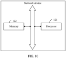
- FIG. 10 is a schematic diagram of a structure of a network device according to an embodiment of this application.
- the network device may be configured to perform the data transmission methods in the embodiments corresponding to FIG. 3 to FIG. 9 .
- the network device may include: components such as a processor 121 and a memory 122. These components are connected and communicate with each other by using one or more buses.
- the processor 121 is a control center of the network device, connects various parts of an entire gNB by using various interfaces and lines, and performs various functions and/or data processing of the gNB by running or executing a software program and/or module stored in the memory 122 and invoking data stored in the memory 122.
- the processor 121 may include an integrated circuit (integrated circuit, IC for short), for example, may include a single packaged IC, or may include a plurality of packaged ICs connected to a same function or different functions.
- the processor 121 may be a communication processor (communication processor, CP for short).
- the memory 122 may be configured to store a software program and a module.
- the processor 121 runs the software program and the module that are stored in the memory 122, to implement various function applications and data processing of the network device.
- the memory 122 may include a volatile memory, for example, a nonvolatile random access memory (nonvolatile random access memory, NVRAM for short), a phase change random access memory (phase change RAM, PRAM for short), or a mageto-resistive random access memory (mageto-resistive RAM, MRAM for short), and may further include a nonvolatile memory, for example, at least one magnetic disk storage device, an electrically erasable programmable read-only memory (Electrically erasable programmable read-only memory, EEPROM for short), or a flash memory device, for example, an NOR flash memory (NOR flash memory) or an NAND flash memory (NAND flash memory).
- NOR flash memory NOR flash memory
- NAND flash memory NAND flash memory
- FIG. 11 is a schematic diagram of a structure of user equipment according to an implementation of this application.
- the structure of the user equipment may be shown in FIG. 11 , and the UE may include: a processor 110, an external memory interface 120, an internal memory 121, a universal serial bus (universal serial bus, USB) interface 130, a charging management module 140, a power management unit 141, a battery 142, an antenna 1, an antenna 2, a mobile communication module 150, a wireless communication module 160, an audio module 170, a speaker 170A, a receiver 170B, a microphone 170C, a headset jack 170D, a sensor module 180, a button 190, a motor 191, an indicator 192, a camera 193, a display screen 194, a subscriber identification module (subscriber identification module, SIM) card interface 195, and the like.
- a processor 110 an external memory interface 120, an internal memory 121, a universal serial bus (universal serial bus, USB) interface 130, a charging management module 140, a power management unit 141, a battery 142, an antenna 1, an antenna 2, a mobile communication
- the sensor module 180 may include a pressure sensor 180A, a gyroscope sensor 180B, a barometric pressure sensor 180C, a magnetic sensor 180D, an acceleration sensor 180E, a distance sensor 180F, an optical proximity sensor 180G, a fingerprint sensor 180H, a temperature sensor 180J, a touch sensor 180K, an ambient light sensor 180L, a bone conduction sensor 180M, and the like.
- the structure illustrated in this embodiment does not constitute a specific limitation on the UE.
- the UE may include more or fewer components than those shown in the figure, or combine some components, or split some components, or have different component arrangements.
- the components shown in the figure may be implemented by hardware, software, or a combination of software and hardware.
- the processor 110 may include one or more processing units.
- the processor 110 may include an application processor (application processor, AP), a Modem, a graphics processing unit (graphics processing unit, GPU), an image signal processor (image signal processor, ISP), a controller, a video codec, a digital signal processor (digital signal processor, DSP), a baseband processor, and/or a neural-network processing unit (neural-network processing unit, NPU).
- application processor application processor, AP
- Modem graphics processing unit
- graphics processing unit graphics processing unit
- ISP image signal processor
- controller a video codec
- DSP digital signal processor
- baseband processor baseband processor
- neural-network processing unit neural-network processing unit
- Different processing units may be independent devices, or may be integrated into one or more processors.
- the charging management module 140 is configured to receive a charging input from a charger.
- the charger may be a wireless charger or may be a wired charger.
- the power management module 141 is configured to connect the battery 142 and the charging management module 140 to the processor 110.
- the power management module 141 receives an input from the battery 142 and/or an input from the charging management module 140, and supplies power to the processor 110, the internal memory 171, the display screen 194, the camera 193, the wireless communication module 160, and the like.
- a wireless communication function of the UE may be implemented by using the antenna 1, the antenna 2, the mobile communication module 150, the wireless communication module 160, the modem, the baseband processor, and the like.
- the antenna 1 and the antenna 2 are configured to transmit and receive an electromagnetic wave signal.
- Each antenna in the UE may be configured to cover one or more communication frequency bands. Different antennas may be further multiplexed to improve antenna utilization.
- the mobile communication module 150 may provide a solution for wireless communication including 2G/3G/4G/5G and the like applied to the UE.
- the wireless communication module 160 may provide a solution for wireless communication that is applied to the UE and that includes a wireless local area network (wireless local area network, WLAN) (such as a wireless fidelity (wireless fidelity, Wi-Fi) network), Bluetooth (Bluetooth, BT), a global navigation satellite system (global navigation satellite system, GNSS), frequency modulation (frequency modulation, FM), near field communication (near field communication, NFC), and an infrared (infrared, IR) technology.
- the wireless communication module 160 may be one or more devices integrating at least one communication processing module.
- the wireless communication module 160 receives an electromagnetic wave by using the antenna 2, performs frequency modulation and filtering processing on an electromagnetic wave signal, and sends a processed signal to the processor 110.
- the wireless communication module 160 may further receive a to-be-sent signal from the processor 110, perform frequency modulation and amplification on the signal, and convert the signal into an electromagnetic wave for radiation by using the antenna 2.
- the wireless communication module 160 may be used by the UE to send, to a network node, a request for resuming an RRC connection, and receives a response message from the network node.
- the display screen 194 is configured to display an image, a video, or the like.
- a series of graphical user interfaces may be displayed on the display screen 194 of the UE.
- the camera 193 is configured to capture a still image or a video.
- the external memory interface 120 may be configured to connect to an external storage card, for example, a Micro SD card, to extend a storage capability of the UE.
- an external storage card for example, a Micro SD card
- the internal memory 121 may be configured to store computer-executable program code.
- the executable program code includes instructions.
- the processor 110 runs the instructions stored in the internal memory 121, to implement various function applications and data processing of the UE.
- the UE may implement an audio function, for example, music playing and video recording, by using the audio module 170, the speaker 170A, the receiver 170B, the microphone 170C, the headset interface 170D, the application processor, and the like.
- the UE may further include a pressure sensor 180A, a barometric pressure sensor 180C, a gyroscope sensor 180B, a magnetic sensor 180D, an acceleration sensor 180E, a distance sensor 180F, an optical proximity sensor 180G, an ambient light sensor 180L, a fingerprint sensor 180H, a temperature sensor 180J, a touch sensor 180K, a bone conduction sensor 180M, a button 190, a motor 191, an indicator 192, and the like.
- a pressure sensor 180A a barometric pressure sensor 180C, a gyroscope sensor 180B, a magnetic sensor 180D, an acceleration sensor 180E, a distance sensor 180F, an optical proximity sensor 180G, an ambient light sensor 180L, a fingerprint sensor 180H, a temperature
- the SIM card interface 195 is configured to connect to a SIM card.
- the SIM card may be inserted into the SIM card interface 195 or removed from the SIM card interface 195 to implement contact with and separation from the UE.
- the UE may support one or N SIM card interfaces, where N is a positive integer greater than 1.
- the SIM card interface 195 may support a Nano SIM card, a Micro SIM card, a SIM card, and the like. A plurality of cards may be simultaneously inserted into a same SIM card interface 195.
- the SIM card interface 195 may also be compatible with an external storage card. The UE interacts with a network by using the SIM card, to implement functions such as a call making/answering and data communication.
- an operating system is running, such as a Harmony operating system, an iOS operating system, an Android operating system, or a Windows operating system.
- An application may be installed and runs on the operating system. In some other embodiments, there may be a plurality of operating systems running in the UE.
- the hardware modules included in the UE shown in FIG. 11 are merely examples for description, and constitute no limitation on a specific structure of the UE.
- the UE provided in this embodiment of this application may further include another hardware module that has an interaction relationship with the hardware module shown in the figure. This is not specifically limited herein.
- the UE may further include a flash, a micro projection apparatus, and the like.
- the UE may further include components such as a keyboard and a mouse.
- the user equipment shown in FIG. 11 may implement all method steps of the method embodiments on the user equipment side in this application.
- this application further provides a computer storage medium.
- the computer storage medium may store a program, and when the program is executed, some or all of the steps in the embodiments of the data transmission method provided in this application may be included.
- the storage medium may be a magnetic disk, an optical disc, a read-only memory (read-only memory, ROM), a random access memory (random access memory, RAM), or the like.
- the memory in the embodiments of this application may be a volatile memory or a nonvolatile memory, or may include both a volatile memory and a nonvolatile memory.
- the nonvolatile memory may be a read-only memory (read-only memory, ROM), a programmable read-only memory (programmable ROM, PROM), an erasable programmable read-only memory (erasable PROM, EPROM), an electrically erasable programmable read-only memory (electrically EPROM, EEPROM), or a flash memory.
- the volatile memory may be a random access memory (random access memory, RAM), and is used as an external cache.
- RAMs are available, for example, a static random access memory (static RAM, SRAM), a dynamic random access memory (dynamic RAM, DRAM), a synchronous dynamic random access memory (synchronous DRAM, SDRAM), a double data rate synchronous dynamic random access memory (double data rate SDRAM, DDR SDRAM), an enhanced synchronous dynamic random access memory (enhanced SDRAM, ESDRAM), a synch link dynamic random access memory (synch link DRAM, SLDRAM), and a direct ram bus random access memory (direct ram bus RAM, DRRAM).
- static random access memory static random access memory
- DRAM dynamic random access memory
- DRAM dynamic random access memory
- SDRAM synchronous dynamic random access memory
- double data rate SDRAM double data rate SDRAM
- DDR SDRAM double data rate SDRAM
- ESDRAM enhanced synchronous dynamic random access memory
- synch link dynamic random access memory synch link dynamic random access memory
- direct ram bus RAM direct ram bus RAM
- a corresponds to B may be understood as that A is associated with B or A and B have an association relationship.
- the disclosed system, apparatus, and method may be implemented in other manners.
- the apparatus embodiments described above are merely examples.
- division into the units is merely logical function division, and there may be another division manner in actual implementation.
- a plurality of units or components may be combined or integrated into another system, or some features may be ignored or not performed.
- the displayed or discussed mutual couplings or direct couplings or communication connections may be implemented by using some interfaces.
- the indirect couplings or communication connections between the apparatuses or units may be implemented in an electrical form, a mechanical form, or another form.
- the units described as separate parts may or may not be physically separate, and parts displayed as units may or may not be physical units, that is, may be located in one place, or may be distributed on a plurality of network units. Some or all of the units may be selected based on actual requirements to achieve the objectives of the solutions of the embodiments.
- the function When the function is implemented in a form of a software functional unit and sold or used as an independent product, the function may be stored in a computer-readable storage medium. Based on such an understanding, the technical solutions in this application essentially, or the part contributing to the conventional technology, or some of the technical solutions may be implemented in a form of a software product.
- the computer software product is stored in a storage medium and includes several instructions for instructing a computer device (which may be a personal computer, a server, a network device, or the like) to perform all or some of the steps in the methods in the embodiments of this application.
- the foregoing storage medium includes: any medium that can store program code, such as a USB flash drive, a removable hard disk, a read-only memory (read-only memory, ROM), a random access memory (random access memory, RAM), a magnetic disk, or an optical disc.
- program code such as a USB flash drive, a removable hard disk, a read-only memory (read-only memory, ROM), a random access memory (random access memory, RAM), a magnetic disk, or an optical disc.
- An embodiment of this application further provides a storage medium, configured to store a computer program or instructions.
- a storage medium configured to store a computer program or instructions.
- the computer program or the instruction are executed by a processor, the data transmission method in the embodiments of this application is implemented. Same method steps and beneficial effects are not described herein again.
Landscapes
- Engineering & Computer Science (AREA)
- Computer Networks & Wireless Communication (AREA)
- Signal Processing (AREA)
- Mobile Radio Communication Systems (AREA)
Applications Claiming Priority (2)
| Application Number | Priority Date | Filing Date | Title |
|---|---|---|---|
| CN202210573972.4A CN117156526A (zh) | 2022-05-24 | 2022-05-24 | 数据传输方法及相关设备 |
| PCT/CN2023/089727 WO2023226646A1 (zh) | 2022-05-24 | 2023-04-21 | 数据传输方法及相关设备 |
Publications (2)
| Publication Number | Publication Date |
|---|---|
| EP4513984A1 true EP4513984A1 (de) | 2025-02-26 |
| EP4513984A4 EP4513984A4 (de) | 2025-08-13 |
Family
ID=88904815
Family Applications (1)
| Application Number | Title | Priority Date | Filing Date |
|---|---|---|---|
| EP23810720.5A Pending EP4513984A4 (de) | 2022-05-24 | 2023-04-21 | Datenübertragungsverfahren und zugehörige vorrichtung |
Country Status (3)
| Country | Link |
|---|---|
| EP (1) | EP4513984A4 (de) |
| CN (1) | CN117156526A (de) |
| WO (1) | WO2023226646A1 (de) |
Families Citing this family (1)
| Publication number | Priority date | Publication date | Assignee | Title |
|---|---|---|---|---|
| CN117729652B (zh) * | 2024-02-07 | 2024-07-02 | 荣耀终端有限公司 | 通信方法、设备和存储介质 |
Family Cites Families (5)
| Publication number | Priority date | Publication date | Assignee | Title |
|---|---|---|---|---|
| CN107295638B (zh) * | 2016-04-01 | 2019-08-02 | 电信科学技术研究院 | 下行数据的传输方法、基站及终端 |
| CN110475320B (zh) * | 2018-05-11 | 2023-11-21 | 华为技术有限公司 | 传输寻呼消息的方法和装置 |
| EP4144176A4 (de) * | 2020-05-13 | 2024-05-01 | FG Innovation Company Limited | Datenübertragungsverwaltung in inaktivem zustand der funkressourcensteuerung (rrc) |
| CN114126012A (zh) * | 2020-08-28 | 2022-03-01 | 中国移动通信有限公司研究院 | 寻呼处理方法、装置、用户设备及基站 |
| CN116965104A (zh) * | 2020-10-21 | 2023-10-27 | 欧芬诺有限责任公司 | 针对小数据传输的寻呼 |
-
2022
- 2022-05-24 CN CN202210573972.4A patent/CN117156526A/zh active Pending
-
2023
- 2023-04-21 WO PCT/CN2023/089727 patent/WO2023226646A1/zh not_active Ceased
- 2023-04-21 EP EP23810720.5A patent/EP4513984A4/de active Pending
Also Published As
| Publication number | Publication date |
|---|---|
| CN117156526A (zh) | 2023-12-01 |
| WO2023226646A1 (zh) | 2023-11-30 |
| EP4513984A4 (de) | 2025-08-13 |
Similar Documents
| Publication | Publication Date | Title |
|---|---|---|
| US11304054B2 (en) | Communication method and device | |
| EP3751954A1 (de) | Kommunikationsverfahren und -vorrichtung | |
| US12464464B2 (en) | Managing a ue preferred configuration | |
| US20240049327A1 (en) | Communication method, apparatus, and system | |
| CN110178433B (zh) | 一种通信方法、相关设备及系统 | |
| JP7540502B2 (ja) | 端末装置及び基地局 | |
| CN109327917A (zh) | 建立连接的方法及设备 | |
| US20240365282A1 (en) | Managing Paging for a User Device | |
| CN108430070B (zh) | 一种无线资源控制连接方法及设备、计算机存储介质 | |
| CN113747457B (zh) | 配置信息获取方法、装置、用户设备及系统 | |
| CN109246853A (zh) | 一种会话处理方法、装置及系统 | |
| CN103037472A (zh) | 集群登记的方法及装置 | |
| WO2023134410A1 (zh) | 通信方法、装置及系统 | |
| EP4132041B1 (de) | Informationsübertragungsverfahren und -vorrichtung, kommunikationsvorrichtung und speichermedium | |
| CN114698151A (zh) | 定位数据发送方法、接收方法、终端及网络侧设备 | |
| EP4513984A1 (de) | Datenübertragungsverfahren und zugehörige vorrichtung | |
| WO2022041016A1 (zh) | 寻呼消息的处理方法及装置、通信设备和存储介质 | |
| EP4132035B1 (de) | Kommunikationsverfahren und -vorrichtung | |
| CN115004848B (zh) | 无线通信方法和终端设备 | |
| US20250301526A1 (en) | Network configuration method, user equipment, network device, and computer storage medium | |
| US20200252842A1 (en) | Managing cell group configuration in disaggregated base station architecture | |
| WO2023226648A1 (zh) | 数据传输方法及相关设备 | |
| CN114828293A (zh) | 连接保持方法、装置及电子设备 | |
| CN117156500B (zh) | 数据传输方法、网络设备及计算机可读存储介质 | |
| WO2023051366A1 (zh) | 一种控制传输的方法及相关装置 |
Legal Events
| Date | Code | Title | Description |
|---|---|---|---|
| STAA | Information on the status of an ep patent application or granted ep patent |
Free format text: STATUS: THE INTERNATIONAL PUBLICATION HAS BEEN MADE |
|
| PUAI | Public reference made under article 153(3) epc to a published international application that has entered the european phase |
Free format text: ORIGINAL CODE: 0009012 |
|
| STAA | Information on the status of an ep patent application or granted ep patent |
Free format text: STATUS: REQUEST FOR EXAMINATION WAS MADE |
|
| 17P | Request for examination filed |
Effective date: 20241118 |
|
| AK | Designated contracting states |
Kind code of ref document: A1 Designated state(s): AL AT BE BG CH CY CZ DE DK EE ES FI FR GB GR HR HU IE IS IT LI LT LU LV MC ME MK MT NL NO PL PT RO RS SE SI SK SM TR |
|
| REG | Reference to a national code |
Ref country code: DE Ref legal event code: R079 Ref document number: 602023017034 Country of ref document: DE Free format text: PREVIOUS MAIN CLASS: H04W0052020000 Ipc: H04W0068000000 Ref country code: DE Ref legal event code: R079 Free format text: PREVIOUS MAIN CLASS: H04W0052020000 Ipc: H04W0068000000 |
|
| A4 | Supplementary search report drawn up and despatched |
Effective date: 20250715 |
|
| RIC1 | Information provided on ipc code assigned before grant |
Ipc: H04W 68/00 20090101AFI20250709BHEP Ipc: H04W 68/02 20090101ALI20250709BHEP Ipc: H04W 76/27 20180101ALI20250709BHEP Ipc: H04W 52/02 20090101ALN20250709BHEP Ipc: H04W 76/25 20180101ALN20250709BHEP Ipc: H04W 88/02 20090101ALN20250709BHEP Ipc: H04W 88/08 20090101ALN20250709BHEP |
|
| DAV | Request for validation of the european patent (deleted) | ||
| DAX | Request for extension of the european patent (deleted) | ||
| GRAP | Despatch of communication of intention to grant a patent |
Free format text: ORIGINAL CODE: EPIDOSNIGR1 |
|
| STAA | Information on the status of an ep patent application or granted ep patent |
Free format text: STATUS: GRANT OF PATENT IS INTENDED |
|
| RIC1 | Information provided on ipc code assigned before grant |
Ipc: H04W 68/00 20090101AFI20251120BHEP Ipc: H04W 68/02 20090101ALI20251120BHEP Ipc: H04W 76/27 20180101ALI20251120BHEP Ipc: H04W 52/02 20090101ALN20251120BHEP Ipc: H04W 76/25 20180101ALN20251120BHEP Ipc: H04W 88/02 20090101ALN20251120BHEP Ipc: H04W 88/08 20090101ALN20251120BHEP |
|
| INTG | Intention to grant announced |
Effective date: 20251202 |
|
| RIC1 | Information provided on ipc code assigned before grant |
Ipc: H04W 68/00 20090101AFI20251125BHEP Ipc: H04W 68/02 20090101ALI20251125BHEP Ipc: H04W 76/27 20180101ALI20251125BHEP Ipc: H04W 52/02 20090101ALN20251125BHEP Ipc: H04W 76/25 20180101ALN20251125BHEP Ipc: H04W 88/02 20090101ALN20251125BHEP Ipc: H04W 88/08 20090101ALN20251125BHEP |
|
| GRAS | Grant fee paid |
Free format text: ORIGINAL CODE: EPIDOSNIGR3 |
|
| GRAA | (expected) grant |
Free format text: ORIGINAL CODE: 0009210 |
|
| STAA | Information on the status of an ep patent application or granted ep patent |
Free format text: STATUS: THE PATENT HAS BEEN GRANTED |