EP4514048A1 - Terminal et procédé de communication - Google Patents
Terminal et procédé de communication Download PDFInfo
- Publication number
- EP4514048A1 EP4514048A1 EP22938460.7A EP22938460A EP4514048A1 EP 4514048 A1 EP4514048 A1 EP 4514048A1 EP 22938460 A EP22938460 A EP 22938460A EP 4514048 A1 EP4514048 A1 EP 4514048A1
- Authority
- EP
- European Patent Office
- Prior art keywords
- terminal
- transmission
- resource
- channel access
- communication
- Prior art date
- Legal status (The legal status is an assumption and is not a legal conclusion. Google has not performed a legal analysis and makes no representation as to the accuracy of the status listed.)
- Pending
Links
Images


Classifications
-
- H—ELECTRICITY
- H04—ELECTRIC COMMUNICATION TECHNIQUE
- H04W—WIRELESS COMMUNICATION NETWORKS
- H04W56/00—Synchronisation arrangements
- H04W56/001—Synchronization between nodes
- H04W56/0015—Synchronization between nodes one node acting as a reference for the others
-
- H—ELECTRICITY
- H04—ELECTRIC COMMUNICATION TECHNIQUE
- H04W—WIRELESS COMMUNICATION NETWORKS
- H04W56/00—Synchronisation arrangements
- H04W56/001—Synchronization between nodes
- H04W56/002—Mutual synchronization
-
- H—ELECTRICITY
- H04—ELECTRIC COMMUNICATION TECHNIQUE
- H04W—WIRELESS COMMUNICATION NETWORKS
- H04W74/00—Wireless channel access
- H04W74/08—Non-scheduled access, e.g. ALOHA
- H04W74/0808—Non-scheduled access, e.g. ALOHA using carrier sensing, e.g. carrier sense multiple access [CSMA]
-
- H—ELECTRICITY
- H04—ELECTRIC COMMUNICATION TECHNIQUE
- H04W—WIRELESS COMMUNICATION NETWORKS
- H04W92/00—Interfaces specially adapted for wireless communication networks
- H04W92/16—Interfaces between hierarchically similar devices
- H04W92/18—Interfaces between hierarchically similar devices between terminal devices
Definitions
- the present invention relates to a terminal and a communication method in a wireless communication system.
- LTE long term evolution
- LTE-A LTE Advanced
- NR new radio
- D2D device to device technology in which terminals perform direct communication without passing through a base station has been discussed (for example, Non Patent Literature 1).
- D2D reduces traffic between the terminal and the base station, and enables communication between the terminals even when the base station becomes incommunicable at the time of disaster or the like.
- 3GPP 3rd generation partnership project
- D2D is referred to as "sidelink”, but in the present specification, D2D, which is a more general term, is used. However, the term sidelink is also used as necessary in the description of the embodiment to be described later.
- D2D communication is roughly divided into D2D discovery (also referred to as D2D discovery, D2D discovery) for discovering other communicable terminals and D2D communication (also referred to as D2D direct communication, D2D communication, device-to-device direct communication, and the like) for performing direct communication between the terminals.
- D2D communication, the D2D discovery, and the like are simply referred to as D2D when not particularly distinguished from each other.
- a signal transmitted and received in D2D is referred to as a D2D signal.
- V2X vehicle to everything
- NR release 17 the use of a frequency band higher than that in a conventional release (for example, Non Patent Literature 3) is considered.
- a frequency band higher than that in a conventional release for example, Non Patent Literature 3
- an applicable numerology including a sub-carrier spacing, a channel bandwidth, and the like, a design of a physical layer, a failure assumed in actual wireless communication, and the like in a frequency band from 52.6 GHz to 71 GHz have been considered.
- unlicensed bands In new frequency bands in which higher frequencies than in the past are used, unlicensed bands are defined.
- Various regulations are set forth for unlicensed bands, and, for example, LBT (Listen Before Talk) is performed when accessing a channel.
- LBT Listen Before Talk
- S-SSBs idelink SS/PBCH blocks
- the present invention has been made in view of the foregoing, and aims to transmit and receive synchronization signals successfully in terminal-to-terminal direct communication in an unlicensed band.
- a terminal includes: a receiving unit configured to perform sensing in a resource pool set in an unlicensed band; a control unit configured to select a resource based on a result of the sensing and carry out a channel access procedure for a band in which the selected resource is included; and a transmitting unit configured to transmit a signal including at least a synchronization signal to another terminal, in the selected resource, when the channel access procedure is carried out successfully, and the signal including at least the synchronization signal further includes a broadcast channel.
- synchronization signals for terminal-to-terminal direct communication can be successfully transmitted and received in an unlicensed band.
- an existing technology is appropriately used.
- the existing technology is, for example, existing LTE, but the present invention is not limited to the existing LTE.
- LTE Long Term Evolution
- the term "LTE" used in the present specification has a broad meaning including LTE-Advanced, systems subsequent to LTE-Advanced (for example, NR), and a wireless local area network (LAN), unless otherwise specified.
- a duplex system may be a time division duplex (TDD) system, a frequency division duplex (FDD) system, or other systems (for example, flexible duplex and the like).
- TDD time division duplex
- FDD frequency division duplex
- other systems for example, flexible duplex and the like.
- meaning of a radio parameter or the like being “set (configured)" may indicate that a predetermined value is configured in advance (pre-configured), or that a radio parameter indicated by a base station 10 or a terminal 20 is configured.
- Fig. 1 is a diagram illustrating V2X.
- V2X vehicle to everything
- eV2X enhanced V2X
- V2X is a part of intelligent transport systems (ITS), and is a generic name of vehicle to vehicle (V2V) meaning a communication form performed between vehicles, vehicle to infrastructure (V2I) meaning a communication form performed between a vehicle and a road-side unit (RSU) installed beside a road, vehicle to network (V2N) meaning a communication form performed between a vehicle and an ITS server, and vehicle to pedestrian (V2P) meaning a communication form performed between a vehicle and a mobile terminal possessed by a pedestrian.
- V2V vehicle to vehicle
- V2I vehicle to infrastructure
- RSU road-side unit
- V2N vehicle to network
- V2P vehicle to pedestrian
- V2X using LTE or NR cellular communication and device-to-device communication has been discussed.
- V2X using cellular communication is also referred to as cellular V2X.
- studies to realize a large capacity, a low delay, high reliability, and quality of service (QoS) control are in progress.
- V2X of LTE or NR it is expected that the discussions will go beyond the development of the 3GPP technical specifications in the future. For example, it is expected that discussions will be held on achieving interoperability, reducing costs by implementation of an upper layer, a method of using a plurality of radio access technologies (RATs) in parallel or switching between the plurality of RATs, regulatory compliance in each country, and a method of acquiring, distributing, managing a database of, and using data of an LTE or NR V2X platform.
- RATs radio access technologies
- the communication device may be a terminal carried by a person, the communication device may be a device mounted on a drone or an aircraft, or the communication device may be a base station, an RSU, a relay station (a relay node), a terminal having a scheduling capability, or the like.
- sidelink may be distinguished from uplink (UL) or downlink (DL) based on either or a combination of the following 1) to 4). Further, SL may have another name.
- OFDM orthogonal frequency division multiplexing
- CP-OFDM cyclic-prefix OFDM
- DFT-S-OFDM discrete Fourier transform-spread-OFDM
- OFDM without transform precoding OFDM with transform precoding
- Mode 3 and Mode 4 are defined regarding resource allocation of the SL to the terminal 20.
- transmission resources are dynamically allocated by downlink control information (DCI) transmitted from the base station 10 to the terminal 20.
- DCI downlink control information
- SPS semi persistent scheduling
- the terminal 20 autonomously selects a transmission resource from a resource pool.
- a slot in the embodiment of the present invention may be replaced with a symbol, a mini-slot, a sub-frame, a radio frame, or a transmission time interval (TTI).
- a cell in the embodiment of the present invention may be replaced with a cell group, a carrier component, a BWP, a resource pool, a resource, a radio access technology (RAT), a system (including a wireless LAN), or the like.
- RAT radio access technology
- the terminal 20 is not limited to a V2X terminal, and may be any type of terminal that performs D2D communication.
- the terminal 20 may be a terminal such as a smartphone carried by a user, or may be an Internet of Things (IoT) device such as a smart meter.
- IoT Internet of Things
- 3GPP Release 16 or Release 17 sidelink is specified in the technical specifications for 1) and 2) described below.
- an unlicensed band will be a new target of sidelink after 3GPP Release 18.
- the newly targeted unlicensed band is an unlicensed band such as a 5 GHz to 7 GHz band or a 60 GHz band.
- Fig. 2 is a diagram illustrating an example of a frequency range according to the embodiment of the present invention.
- FR1 defined for the current operation is a frequency band from 410 MHz to 7.125 GHz
- the sub carrier spacing (SCS) is 15, 30, or 60 kHz
- the bandwidth is from 5 MHz to 100 MHz.
- FR2 is a frequency band from 24.25 GHz to 52.6 GHz
- the SCS is 60, 120, or 240 kHz
- the bandwidth is 50 MHz to 400 MHz.
- a newly operated frequency band may be expected to be from 52.6 GHz to 71 GHz.
- the unlicensed band in the 5 GHz to 7 GHz band 5.15 GHz to 5.35 GHz, 5.47 GHz to 5.725 GHz, 5.925 GHz or more, and the like are expected.
- 59 GHz to 66 GHz 57 GHz to 64 GHz or 66 GHz, 59.4 GHz to 62.9 GHz, and the like are expected.
- LBT listen before talk
- the base station 10 or the terminal 20 performs power detection in a predetermined period immediately before performing transmission, and stops transmission when the power exceeds a certain value, that is, when detecting transmission of another device.
- a maximum channel occupancy time (MCOT) is defined.
- the MCOT is a maximum time period during which transmission is allowed to be continued when the transmission is started after LBT, and is, for example, 4 ms in Japan.
- OCB occupied channel bandwidth
- X% or more of the band needs to be used when transmission is performed using a certain carrier bandwidth. For example, in Europe, it is required to use 80% to 100% in a nominal channel bandwidth (NCB).
- the OCB requirement is intended to ensure that power detection of channel access is performed correctly.
- maximum transmission power and maximum power spectral density it is specified that transmission is performed at predetermined transmission power or less. For example, in Europe, 23 dBm is the maximum transmission power in a 5,150 MHz to 5,350 MHz band. In addition, for example, in Europe, the maximum power spectral density is 10 dBm/MHz in the 5,150 MHz to 5,350 MHz band.
- LBT is executed at the time of channel access in the 60 GHz band.
- the base station 10 or the terminal 20 performs power detection in a predetermined period immediately before performing transmission, and stops transmission when the power exceeds a certain value, that is, when detecting transmission of another device.
- a certain value that is, when detecting transmission of another device.
- transmission is performed at predetermined transmission power or less. It is also specified to have a capability to meet the OCB requirement.
- the nominal channel bandwidth is a maximum bandwidth including a guard band allocated to a single channel, and may be 20 MHz.
- the bandwidth allocated to a single channel to be operated may be an LBT bandwidth.
- an occupied channel bandwidth may be defined as a bandwidth including 99% of signal power.
- NR In NR, four types of channel access procedures described below are defined based on a difference in behavior of time reporting of LBT (period during which sensing is performed).
- Type 1 Variable time sensing is executed before transmission.
- Type 1 is also referred to as category-4 LBT.
- Type 2A 25 ⁇ s sensing is executed before transmission.
- Type 2A is also referred to as category-2 LBT.
- Type 2B 16 ⁇ s sensing is executed before transmission.
- Type 2B is also referred to as category-2 LBT.
- Type 2C Transmission starts without performing LBT.
- Type 2C is similar to transmission in the licensed band.
- Fig. 3 is a diagram illustrating an example (1) of LBT.
- Fig. 3 is an example of a channel access procedure of Type 1.
- Type 1 is further classified into four classes indicating a channel access priority class based on a difference in sensing length. Sensing is executed in the following two periods of time.
- a first period is a prioritization period or a defer duration and has a length of 16 + 9 ⁇ m p [ ⁇ s].
- a fixed value of m p is defined for each channel access priority class.
- a second period is a back-off procedure and has a length of 9 ⁇ N[ ⁇ s].
- the value of N is randomly determined from a certain range (refer to Non Patent Literature 4).
- the 9 ⁇ s sensing period may be referred to as a sensing slot period.
- m p 3
- a defer duration is 43 ⁇ s.
- a back-off counter is fixed during the channel-busy state.
- a contention window size is increased from 3 to 13 in the NR-U gNB.
- Fig. 4 is a diagram illustrating an example (2) of LBT.
- Fig. 4 is an example of the channel access procedure of Type 2A or Type 2B without random back-off.
- a gap for performing power detection of 25 ⁇ s for Type 2A or 16 ⁇ s for Type 2B is configured before transmission.
- Fig. 5 is a diagram illustrating an example (3) of LBT.
- Fig. 5 is an example of the channel access procedure of Type 2C. As illustrated in Fig. 5 , no power detection is performed before transmission, and after a gap not exceeding 16 ⁇ s, transmission is performed immediately. The transmission period may be up to 584 ⁇ s.
- a DL transmission burst is defined as a set of transmissions from an eNB or gNB, without a gap longer than 16 ⁇ s therein. If a gap exceeding a length determined to divide DL transmission bursts is present, then the multiple transmissions from the eNB or gNB are separated. The eNB or gNB may perform transmissions after the gap in the DL transmission burst without performing sensing to determine the availability of the corresponding channel.
- a UL transmission burst is defined as a set of transmissions from a UE, without a gap longer than 16 ⁇ s therein. If a gap longer than 16 ⁇ s divides UL transmission bursts, then the multiple transmissions from the UE are separated. The UE may perform transmissions after the gap in the UL transmission burst without performing sensing to determine the availability of the corresponding channel.
- the conditions for the use of channel access procedures other than type 1 include the following (1) to (4):
- the DG-PUSCH or the PUCCH can be transmitted during the COT in the ongoing type 1 channel access procedures if the CAPC value in the ongoing type 1 channel access procedures is greater than or equal to the CAPC value for the new PUSCH/PUCCH. In other words, there is no need to cause the type 1 channel access procedures to be run.
- the ongoing type 1 channel access procedures must be interrupted 1 channel access procedures must be carried out based on the newly indicated CAPC value.
- the PUCCH can always be transmitted during the COT of ongoing type 1 channel access procedures, and so there is no need to cause new type 1 channel access procedures to be run.
- the CAPCs of radio bearers and MAC-CEs can be configured to be fixed or variable.
- the padding BSR and recommended-bit-rate MAC-CEs are always set to the lowest priority.
- SRB0, SRB1, SRB3 and other MAC-CEs are always set to the highest priority.
- the priority of SRB2 and DRBs can be set by the gNB.
- the gNB When selecting a DRB's CAPC, the gNB takes into account the 5QIs of all QoS flows (5G QoS Identifiers) multiplexed over that DRB, considering the fairness between different traffic types and transmissions.
- Table 1 shows the mapping of CAPCs used for standardized 5QIs. [Table 1] CAPC 5QI 1 1, 3, 5, 65, 66, 67, 69, 70, 79, 80, 82, 83, 84, 85 2 2, 7, 71 3 4, 6, 8, 9, 72, 73, 74, 76 4 - NOTE: Smaller CAPC values indicate higher priorities.
- the CAPCs shown in Table 1 are used for QoS flows.
- a QoS flow corresponding to a non-standardized 5QI (that is, an operator-specific 5QI) should use the CAPC of a standardized 5QI that matches the QoS characteristics of the non-standardized 5QI.
- the UE selects the CAPC as follows:
- the transport block contains only MAC-CEs, the highest CAPC among the CAPCs of these MAC-CEs is used. If the transport block contains CCCH-SDUs, the highest CAPC is used. Alternatively, if the transport block contains DCCH-SCUs, the highest CAPC among the CAPCs of the DCCHs is used. Alternatively, the lowest CAPC among the CAPCs of logical channels with MAC-SDUs multiplexed over the transport block may be used.
- the sensing period in the back-off procedure during type 1 channel access procedures is randomly selected from a specific range ⁇ 0 ... CW ⁇ .
- the CW value is selected from the range from CWmin (minimum CW) to CWmax (maximum CW) in Table 2 below, based on the CWS (Contention Window Size) adjustment procedure defined in non-patent document 4.
- the minimum CW and the maximum CW are set to different values per channel access priority class. In higher class numbers, the minimum CW and maximum CW are set to larger values. Therefore, the higher the class number, the lower the possibility of collisions with other devices and the longer the time required for channel access procedures. On the other hand, the lower the class number, the higher the possibility of collisions with other devices and the shorter the time required for channel access procedures.
- the maximum COT shown in Table 2 is the maximum channel occupancy time.
- the initial CW value is the minimum CW.
- the CW value is incremented based on the decoded results from past PDSCH transmissions or PUSCH transmissions.
- FIG. 6 shows an example of multi-PUSCH scheduling.
- a multi-TTI (Transmission Time Interval) grant is used to schedule multiple PUSCHs over multiple slots/mini-slots with one DCI (Downlink Control Information).
- DCI Downlink Control Information
- HARQ Hybrid Automatic Repeat reQuest
- an NDI New Data Indicator
- an RV Redundancy Version
- the HARQ process ID indicated in that DCI is applied to the first PUSCH that is scheduled, and, as for the HARQ process IDs of subsequent PUSCHs, a value incremented by one in the order of the PUSCHs is applied to each PUSCH.
- the user terminal 20 performs LBT before the slot labeled "A,” in which the first PUSCH is scheduled. If the result of that LBT is OK, the user terminal 20 transmits data in four contiguous PUSCHs. If the result of the first LBT is NG, LBT is performed before the slot labeled "B,” in which a PUSCH is scheduled, and, if the result of this LBT is OK, the user terminal 20 transmits data in three contiguous PUSCHs. The same process is performed thereafter. If LBT is performed before the slot labeled "D,” in which the last PUSCH is scheduled and its result is NG, no transmission is performed.
- PUSCH scheduling may be configured such that one DCI supports multiple slots or mini-slots including multiple contiguous PUSCHs that may include multiple separated TBs.
- DCI signaling multiple PUSCHs may include the NDIs and RVs.
- CBG (Code Block Group)-based retransmission may be supported in multiple PUSCH scheduling, and may be signaled for every one or more PUSCHs to be retransmitted, for every PUSCH, or for every fixed number of PUSCHs, in a field in DCI.
- the HARQ process ID signaled in DCI may be applied to the first-scheduled PUSCH and may be incremented by one in every following PUSCH.
- the time-domain resource allocation for PUSCH scheduling may be expanded.
- the range of the starting symbol's position and the ending symbol's position may be expanded, consecutive time-domain resource allocation may be expanded, multiple PUSCHs may be positioned in the leading slot, multiple starting symbol positions may be supported in a terminal-initiated COT, and so forth.
- multiple PUSCH transmissions can be scheduled, in the direction of time, by one UL grant (PDCCH).
- PDCCH UL grant
- Channel access procedures using LBT can be run multiple times. Also, once channel access is successfully gained, the subsequent PUSCH transmissions are carried out as contiguous transmissions in the direction of time, which makes LBT unnecessary.
- Table 3 shows a part of the resource pool configuration for sidelink.
- SCS [kHz] Minimum subchannel size [MHz] Maximum subchannel size [MHz] Maximum configurable bandwidth [MHz] 15 1.8 18 486 30 3.6 36 972 60 7.2 72 1944
- the minimum sub-channel size, the maximum sub-channel size, and the maximum configurable bandwidth are defined for each SCS.
- the size of the frequency domain of a sub-channel is indicated by the number of PRBs, ⁇ 10, 12, 15, 20, 25, 50, 75, 100 ⁇ may be available to be configured.
- the number of sub-channels in the resource pool may be configurable to be 1 to 27.
- the resource pool includes only consecutive RBs and includes only consecutive sub-channels.
- Fig. 7 is a diagram illustrating an example of LBT according to the embodiment of the present invention.
- the terminal 20 selects a resource and performs transmission.
- the terminal 20 executes sensing with a sensing window in the resource pool.
- the terminal 20 receives a resource reservation field or a resource assignment field included in sidelink control information (SCI) transmitted from another terminal 20, and identifies, based on the field, available resource candidates in a resource selection window in the resource pool. Subsequently, the terminal 20 randomly selects a resource from the available resource candidates.
- SCI sidelink control information
- the configuration of the resource pool may have a period.
- the period may be a period of 10,240 milliseconds.
- Fig. 7 illustrates an example in which slots t 0 st to t Tmax-1 SL are configured as a resource pool.
- a region of the resource pool in each period may be configured by, for example, a bitmap.
- a transmission trigger in the terminal 20 occurs in the slot n, and the priority of the transmission is p TX .
- the terminal 20 can detect, for example, that another terminal 20 is performing transmission of a priority p RX in the sensing window from the slot n-T 0 to the slot immediately before the slot n-T proc,0 .
- RSRP reference signal received power
- a threshold value may be, for example, a threshold value Th pTx,pRx configured or defined for each resource in the sensing window based on the priority p TX and the priority p RX .
- a resource in a resource selection window which is a candidate for resource reservation information, corresponding to a resource in a sensing window such as a slot t m SL illustrated in Fig. 7 which was not monitored due to the transmission, is excluded.
- a resource selection window from a slot n+T 1 to a slot n+T 2 as illustrated in Fig. 7 , resources obtained by excluding a resource identified to be occupied by another UE become available resource candidates.
- a set of available resource candidates is defined as S A
- the threshold value Th pTx,pRx configured for each resource of the sensing window may be increased by 3 dB, and resource identification may be executed again. That is, by increasing the threshold value Th pTx,pRx and executing the resource identification again, resources which are not excluded because the RSRP is less than the threshold value may be increased, and the set S A of resource candidates may become 20% or more of the resource selection window.
- the operation of increasing the threshold value Th pTx,pRx configured for each resource of the sensing window by 3 dB and of executing the resource identification again may be repeatedly performed.
- a lower layer of the terminal 20 may report S A to an upper layer thereof.
- the upper layer of the terminal 20 may execute random selection on S A to determine a resource to be used.
- the terminal 20 may execute sidelink transmission by using the determined resource.
- the upper layer may be a MAC layer
- the lower layer may be a PHY layer or a physical layer.
- the reception side terminal 20 may detect data transmission from another terminal 20 based on a result of sensing or partial sensing and may receive data from the another terminal 20.
- the terminal 20 executes a sensing and resource selection procedure in a 3GPP Release 16/17 sidelink.
- the terminal 20 executes the above-described channel access procedure (3GPP Release 16 NR-U/ETSI broadband radio access networks (BRAN)) on a band corresponding to the resource selected in the first step).
- BRAN broadband radio access networks
- Fig. 8 is a diagram illustrating an example of a sidelink according to the embodiment of the present invention.
- a control signal and a data signal of the sidelink may be configured.
- Fig. 8 illustrates an example in which three sub-channels are used for transmission of PSCCH and PSSCH.
- SCI is separated into a first stage SCI and a second stage SCI.
- the first stage SCI is transmitted via PSCCH
- the second stage SCI is transmitted via PSSCH.
- PSCCH carrying the first stage SCI does not exceed one sub-channel width and includes ⁇ 10, 12, 15, 20, 25 ⁇ PRBs and 2 or 3 symbols.
- the second symbol is copied to the first symbol for AGC.
- the last symbol is used as a gap for switching between transmission and reception.
- Table 4 shows a 1st-stage SCI format 1-A in a 2-stage SCI format.
- 1 st-stage SCI SCI format 1-A Field Number of bits Priority 3 Resource reservation period A* or 0 Time resource assignment 5 or 9 Frequency resource assignment B* or C* DM-RS pattern 0 or 1 or 2 2nd stage SCI format 2 Beta offset indicator 2 Number of DM-RS ports 1 MCS 5 Additional MCS table 2 or 0 PSFCH overhead 1 or 0 Reserved 2 to 4
- bit duration of the priority field is 3 bits.
- the bit duration of the resource reservation period field is determined by the following mathematical expression 1, or is 0.
- A* log 2 N reservPeriod
- N reservPeriod in the mathematical expression 1 is the reservation period.
- the bit duration of the time resource assignment field is 5 or 9 bits.
- the bit duration of the frequency resource assignment field is determined by the following mathematical expression 2 or mathematical expression 3.
- B * log 2 N subChannel SL N subChannel SL + 1 2
- C * log 2 N subChannel SL N subChannel SL + 1 2 N subChannel SL + 1 6
- Table 5 shows the 2nd-stage SCI format 2-A.
- the 2nd-stage SCI format 2-A can be received by decoding the 1st-stage SCI.
- 2nd-stage SCI SCI format 2-A Field Number of bits L1 source ID 8 L1 destination ID 16 HARQ process ID 4 New data indicator 1 Redundancy version 2 HARQ feedback enabled/disabled 1 Cast type 2 CSI request 1
- the bit duration of the LI source ID field is 8 bits.
- the bit duration of the L1 destination ID field is 16 bits.
- the bit duration of the HARQ process ID field is 4 bits.
- the bit duration of the new data indicator field is 1 bit.
- the bit duration of the redundancy version field is 2 bits.
- the bit duration of the HARQ feedback enabled/disabled field is 1 bit.
- the bit duration of the cast type field is 2 bits.
- the bit duration of the CSI request field is 1 bit.
- Table 6 shows the 2nd-stage SCI format 2-B.
- the 2nd-stage SCI format 2-B can be received by decoding the 1st-stage SCI.
- the 2nd-stage SCI format 2-B is used for groupcast.
- 2nd-stage SCI SCI format 2-B Field Number of bits L1 source ID 8 L1 destination ID 16 HARQ process ID 4 New data indicator 1 Redundancy version 2 HARQ feedback enabled/disabled 1 Zone ID 12 Communication range requirement 4
- the bit duration of the LI source ID field is 8 bits.
- the bit duration of the L1 destination ID field is 16 bits.
- the bit duration of the HARQ process ID field is 4 bits.
- the bit duration of the new data indicator field is 1 bit.
- the bit duration of the redundancy version field is 2 bits.
- the bit duration of the HARQ feedback enabled/disabled field is 1 bit.
- the bit duration of the zone ID field is 12 bits.
- the bit duration of the communication range requirement field is 4 bits.
- FIG. 9 is a diagram that shows an example of resource allocation mode 1.
- resource allocation mode 1 SL transmission resources are allocated from the base station 10 to the terminal 20A. That is, as shown in FIG. 3 , SL transmission resources (PSCCH/PSCCH) are allocated to the terminal 20A by a PDCCH received from the base station 10 (to be more specific, DCI), and the terminal 20A performs SL transmissions to the terminal 20B using these transmission resources.
- PSCCH/PSCCH SL transmission resources
- a dynamic grant (DG), a configured grant (CG) type 1, and a CG type 2 are used.
- DG dynamic grant
- CG configured grant
- CG type 2 a CG type 2
- resource allocation mode 1 a DCI format 3_0 is used for DG and CG type 2. Note that the monitoring occasions in DCI format 3_0 are configured differently from other formats.
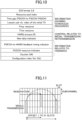
- FIG. 10 is a diagram for explaining an example of DCI format.
- the information indicated by DCI format 3_0 includes information about the scheduled resources, information about the initial transmission/retransmissions, and information about HARQ (Hybrid Automatic Repeat reQuest) feedback.
- the transmitting terminal 20A manages the association between the HPN (HARQ Process Number) indicated in DCI format 3_0 and the HPN indicated in SCI.
- HPN HARQ Process Number
- the terminal 20 autonomously selects resources for periodic or aperiodic traffic by performing the following two steps. When this takes place, periodic or aperiodic resource reservations by other terminals 20 are taken into account.
- Step 1 Identifying candidate resources in the resource selection window.
- Step 2 Selecting resources to be used for transmissions or retransmissions from the identified candidates.
- Step 1 above is performed based on two types of resource reservations.
- the first one is a reservation of aperiodic traffic for transmission or retransmission by the time resource assignment field.
- the second one is a reservation of periodic traffic for transmissions or retransmissions by the resource reservation period field.
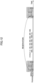
- FIG. 11 shows an example (1) of resource allocation mode 2.
- multiple aperiodic resources may be reserved in a single transmission.
- the offset from the transmission of a reservation to the reserved resources may vary from 1 slot to 31 slots.
- FIG. 12 shows an example (2) of resource allocation mode 2.
- resources may be reserved periodically after a single transmission is made.
- the periodicity here may be, for example, 0 ms, 1 ms to 99 ms, 100 ms, 200 ms, 300 ms, 400 ms, 500 ms, 600 ms, 700 ms, 800 ms, 900 ms, 1,000 ms.
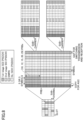
- FIG. 13 is a diagram for explaining an example (1) of synchronization in sidelink communication according to an embodiment of the present invention.
- Table 7 shows the priority levels of synchronization sources in GNSS-based synchronization and gNB/eNB-based synchronization.
- Table 7 Priority level GNSS-based synchronization gNB/eNB-based synchronization P0 GNSS gNB/eNB P1 All UEs directly synchronized with GNSS All UEs directly synchronized with gNB/eNB P2 All UEs indirectly synchronized with GNSS All UEs indirectly synchronized with gNB/eNB P3 gNB/eNB GNSS P4 All UEs directly synchronized with gNB/eNB All UEs directly synchronized with GNSS P5 All UEs indirectly synchronized with gNB/eNB All UEs indirectly synchronized with GNSS P6 Other UEs Other UEs Other UEs Other UEs Other UEs Other UEs
- FIG. 13 shows an example of gNB/eNB-based synchronization.
- each UE transmits an S-SSB, based on the selected synchronization source, to another UE.
- the priority level P0 corresponds to the gNB/eNB.
- the priority level P1 corresponds to UEs that synchronize directly with the gNB/eNB.
- the priority level P2 corresponds to UEs that synchronize indirectly with the gNB/eNB.
- the priority level P3 corresponds to a GNSS.
- the priority level P4 corresponds to UEs that synchronize directly with the GNSS.
- the priority level P5 corresponds to UEs that synchronize indirectly with the GNSS.
- the priority level P6 corresponds to other UEs. If the UE detects multiple synchronization sources of the same priority level, the UE may select a synchronization source based on RSRP.
- FIG. 14 is a diagram for explaining an example (2) of synchronization in sidelink communication according to an embodiment of the present invention.
- an S-SSB is composed of an S-PSS (Sidelink-Primary Synchronization Signal), an S-SSS (Sidelink-Secondary Synchronization Signal), and a PSBCH.
- the periodicity of S-SSBs is 160 ms at all subcarrier spacings.
- AGC Access Control
- a transient period is assumed
- the PSBCH necessitates positioning of DM-RS.
- the number of S-SSBs transmitted in one period is determined based on the FR and subcarrier spacing.
- the number of S-SSBs transmitted in one period is 1 when the SCS is 15 kHz, 1 or 2 when the SCS is 30 kHz, and 1, 2, or 4 when the SCS is 60 kHz.
- the number of S-SSBs transmitted in one period is 1, 2, 4, 8, 16, or 32 when the SCS is 60 kHz, and 1, 2, 4, 8, 16, 32, or 64 when the SCS is 120 kHz. These numbers may be used for beam management.
- the S-PSS and the S-SSS are used to detect the slot and symbol timings, source ID, and so forth.
- S-PSS an M sequence that is 127 bits long is used.
- S-SSS a Gold sequence that is 127 bits long is used (see Non-Patent Document 1).
- the PSBCH contains information related to SL synchronization.
- S-SSBs' frequency resources are configured or pre-configured.
- Table 8 shows the SL-SSIDs indicated by the S-PSS and the S-SSS per synchronization source type.
- the SL-SSID is configured to 0. If the cell (eNB/gNB) is the source of synchronization, the SL-SSID is configured to any value between 1 and 335. If a UE that synchronizes directly with the eNB/gNB is the source of synchronization, the SL-SSID that is received is configured as is. If a UE that synchronizes indirectly with the eNB/gNB is the source of synchronization, 336 is added to the SL-SSID that is received, and the resulting value is configured. If a UE that synchronizes directly with the GNSS is the source of synchronization, the SL-SSID is configured to 0.
- the SL-SSID is configured to 337. If there is no synchronization source, the SL-SSID will be a randomly selected value between 338 and 671.
- Table 9 shows the contents and bit duration of the PSBCH. [Table 9] Contents Number of bits Direct frame number 10 Indication of TDD configuration Pattern 1 Periodicity 4 UL slots 7 Slot index 7 In-coverage indicator 1 Reserved bits 2 CRC 24 Total bits 56
- the direct frame number is indicated using 10 bits.
- the pattern is indicated using 1 bit
- the periodicity is indicated using 4 bits
- the UL slots are indicated using 7 bits.
- the slot index is indicated using 7 bits.
- the in-coverage indicator is indicated using 1 bit.
- the reserved bits are 2 bits long.
- the CRC is 24 bits long.
- the total number of PSBCH bits is 56.
- the S-SSB is transmitted a predetermined number of times within 160 ms.
- the predetermined number of times is determined based on SCS.
- 3GPP Release 16 NR-U sets forth a discovery burst (DB) and a discovery burst transmission window (DBTW) to reduce the impact of failures of LBT on the transmission of SSBs for gaining synchronization and other transmissions.
- a discovery burst collectively defines an SSB, a CORESET #0-PDCCH, and an SIB1-PDSCH.
- DBTW allows the number of occasions for transmitting DBs, that is, SSBs, to be set greater than the actual number of SSB beams.
- a discovery burst for sidelink communication may be provided.
- Option 2 Channel access procedures for the S-SSB or sidelink discovery burst may be provided.
- Transmission occasions (the number of transmissions, transmission position candidates, etc.) for the S-SSB or sidelink discovery burst may be increased.
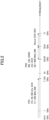
- FIG. 15 is a flowchart for explaining an example of sidelink communication in an unlicensed band according to an embodiment of the present invention.
- the terminal 20 acquires a sidelink resource allocation.
- the terminal 20 may receive the sidelink resource allocation from the base station 10, or a resource pool may be configured.
- the terminal 20 carries out sensing and resource selection procedures.
- Step S2 may be performed in the resource pool in the event resource allocation mode 2 is used.
- the terminal 20 carries out channel access procedures with respect to the band where the selected resource is located.
- the above options 1 and 3 may be applied to the sidelink transmission in the above step.
- the above option 2 may be applied to the channel access procedures of step S2.
- sensing in NR-U is for measuring the RSSI (Received Signal Strength Indicator) of a certain channel during channel access procedures performed prior to a transmission.
- the RSSI value is compared against a threshold to determine whether or not the channel is occupied by another device.
- sensing in UR-U will be referred to as "LBT sensing.”
- sidelink sensing works such that the RSRPs of all subchannels included in the resource pool are measured, and the resource candidates for performing a sidelink transmission are measured. Based on these measurement values, resources that are available for use from the present point in time until a certain period of time later, that is, sidelink transmission resource candidates, are selected.
- SL resource sensing sensing in sidelink will be referred to as "SL resource sensing.”
- one or multiple signals or channels may be collectively defined as one set of transmissions.
- This "transmission set” may be referred to as (1) to (4) below:
- the signals or channels that may be included in this set of transmissions may be any one or more of (1) to (5) below:
- the above-described option 1 allows a specific transmission (set) to be carried out based on a specific LBT, regardless of whether or not there is a gap in the SL transmission (set) in the direction of time or the gap's length in the direction of time.
- the terminal 20 may use channel access procedures in which LBT sensing is performed at fixed times.
- the channel access procedures in which the time of LBT is thus fixed may be any of (1) to (4) shown below:
- An S-SSB transmission may be replaced with either of the following (1) and (2):
- Option 2 above may be applicable if one or more of the following conditions (1) to (3) are satisfied:
- the above option 2 thus allows the terminal 20 to carry out channel access procedures suitable for the S-SSB or sidelink discovery burst.
- Option 3 The number of transmission occasions (the number of transmissions, candidate transmission positions, etc.) for the S-SSB or sidelink discovery bursts may be increased.” will be explained.
- the number of times to transmit the S-SSB in sidelink communication in an unlicensed band may be newly specified. Provisions regarding the transmission of the S-SSB may be set forth as shown below in (1) to (3) .
- a new number of times of S-SSB transmissions may also be specified.
- the parameter "sl-NumSSB-WithinPeriod(-r18)" may be specified.
- the setting related to option 3 above may be configured or pre-configured. Also, the setting related to option 3 may be changed by RRC signaling.
- This RRC signaling may be RRC signaling from the base station 10 or may be PC5-RRC signaling.
- the above option 3 allows the S-SSB to be transmitted frequently enough to gain synchronization even if the frequency of transmitting the S-SSB decreases due to failures of LBT.
- the above embodiment may be applied to an operation in which one terminal 20 configures or allocates transmission resources for another terminal 20.
- the above embodiment is not limited to V2X terminals, and may be applied to terminals that perform D2D communication.
- synchronization signals for terminal-to-terminal direct communication can be transmitted and received successfully in an unlicensed band.
- the base station 10 and the terminal 20 include a function of implementing the above-described embodiment. However, each of the base station 10 and the terminal 20 may have only a part of functions in the embodiment.
- Fig. 16 is a diagram illustrating an example of a functional configuration of the base station 10.
- the base station 10 includes a transmission unit 110, a reception unit 120, a configuration unit 130, and a control unit 140.
- the functional configuration illustrated in Fig. 16 is merely an example. As long as the operation according to the embodiment of the present invention can be executed, the functional classification and the name of the functional units may be freely selected.
- the transmission unit 110 has a function of generating a signal to be transmitted to the terminal 20 side and wirelessly transmitting the signal.
- the reception unit 120 has a function of receiving various signals transmitted from the terminal 20 and acquiring, for example, information of an upper layer from the received signals.
- the transmission unit 110 has a function of transmitting NR-PSS, NR-SSS, NR-PBCH, a DL/UL control signal, a DL reference signal, and the like to the terminal 20.
- the configuration unit 130 stores setting information set in advance and various types of setting information to be transmitted to the terminal 20 in a storage device, and reads the setting information from the storage device as necessary.
- a content of the setting information is, for example, information related to setting of the D2D communication.
- the control unit 140 performs processing related to setting for the terminal 20 to perform the D2D communication. Furthermore, the control unit 140 transmits scheduling of the D2D communication and the DL communication to the terminal 20 via the transmission unit 110. Furthermore, the control unit 140 receives information regarding HARQ responses of the D2D communication and the DL communication from the terminal 20 via the reception unit 120.
- the functional unit related to signal transmission in the control unit 140 may be included in the transmission unit 110, and the functional unit related to signal reception in the control unit 140 may be included in the reception unit 120.
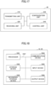
- Fig. 17 is a diagram illustrating an example of a functional configuration of the terminal 20.
- the terminal 20 includes a transmission unit 210, a reception unit 220, a configuration unit 230, and a control unit 240.
- the functional configuration illustrated in Fig. 17 is merely an example. As long as the operation according to the embodiment of the present invention can be executed, the functional classification and the name of the functional units may be freely selected.
- the transmission unit 210 generates a transmission signal from transmission data and wirelessly transmits the transmission signal.
- the reception unit 220 wirelessly receives various signals and acquires a signal of an upper layer from the received signals of a physical layer. Furthermore, the reception unit 220 has a function of receiving NR-PSS, NR-SSS, NR-PBCH, a DL/UL/SL control signal, a reference signal, and the like transmitted from the base station 10.
- the transmission unit 210 transmits a physical sidelink control channel (PSCCH), a physical sidelink shared channel (PSSCH), a physical sidelink discovery channel (PSDCH), a physical sidelink broadcast channel (PSBCH), or the like to the other terminal 20 as the D2D communication, and the reception unit 220 receives PSCCH, PSSCH, PSDCH, PSBCH, or the like from the other terminal 20.
- PSCCH physical sidelink control channel
- PSSCH physical sidelink shared channel
- PSDCH physical sidelink discovery channel
- PSBCH physical sidelink broadcast channel
- the configuration unit 230 stores various types of setting information received from the base station 10 or the terminal 20 by the reception unit 220 in a storage device, and reads the setting information from the storage device as necessary.
- the configuration unit 230 also stores setting information set in advance.
- a content of the setting information is, for example, information related to setting of the D2D communication.
- the control unit 240 controls the D2D communication for establishing an RRC connection with another terminal 20. Furthermore, the control unit 240 performs processing related to a power saving operation. Furthermore, the control unit 240 performs processing related to HARQ of the D2D communication and the DL communication. Furthermore, the control unit 240 transmits, to the base station 10, information regarding HARQ responses of the D2D communication and the DL communication scheduled from the base station 10 to another terminal 20. Furthermore, the control unit 240 may schedule the D2D communication to another terminal 20. Furthermore, the control unit 240 may autonomously select a resource to be used for the D2D communication from a resource selection window based on a result of sensing, or may execute reevaluation or pre-emption.
- control unit 240 performs processing related to power saving in transmission and reception of the D2D communication. Furthermore, the control unit 240 performs processing related to inter-terminal cooperation in the D2D communication.
- the functional unit related to signal transmission in the control unit 240 may be included in the transmission unit 210, and the functional unit related to signal reception in the control unit 240 may be included in the reception unit 220.
- each functional block may be implemented by using one physically or logically combined device, or may be implemented by directly or indirectly (for example, by using wired, wireless, or the like) connecting two or more physically or logically separated devices to each other and using the plurality of devices.
- the functional block may be implemented by combining software with the one device or the plurality of devices.
- the functions include, but are not limited to, deciding, determining, judging, calculating, computing, processing, deriving, investigating, searching, confirming, receiving, transmitting, outputting, accessing, resolving, selecting, choosing, establishing, comparing, assuming, expecting, considering, broadcasting, notifying, communicating, forwarding, configuring, reconfiguring, allocating and mapping, assigning, and the like.
- a functional block (configuration unit) that causes transmission to function is referred to as a transmission unit (transmitting unit) or a transmitter.
- the implementation method is not particularly limited.
- the base station 10, the terminal 20, and the like in the embodiment of the present disclosure may function as a computer that performs processing of a wireless communication method of the present disclosure.
- Fig. 18 is a diagram illustrating an example of hardware configurations of the base station 10 and the terminal 20 according to the embodiment of the present disclosure.
- the base station 10 and the terminal 20 described above may be physically configured as a computer device including a processor 1001, a storage device 1002, an auxiliary storage device 1003, a communication device 1004, an input device 1005, an output device 1006, a bus 1007, and the like.
- the term "device” can be replaced with a circuit, a device, a unit, or the like.
- the hardware configurations of the base station 10 and the terminal 20 may be configured to include one or more devices illustrated in the drawing, or may be configured without including a part of devices.
- Each function in the base station 10 and the terminal 20 is implemented by the processor 1001 performing calculation by loading predetermined software (program) on hardware such as the processor 1001 and the storage device 1002, controlling communication by the communication device 1004, and controlling at least one of reading and writing of data in the storage device 1002 and the auxiliary storage device 1003.
- predetermined software program
- the processor 1001 operates, for example, an operating system to control the entire computer.
- the processor 1001 may include a central processing unit (CPU) including an interface with a peripheral device, a control device, an arithmetic device, a register, and the like.
- CPU central processing unit
- the control unit 140, the control unit 240, and the like described above may be implemented by the processor 1001.
- the processor 1001 reads a program (a program code), a software module, data, or the like from at least one of the auxiliary storage device 1003 and the communication device 1004 to the storage device 1002, and executes various types of processing according to the program, the software module, the data, or the like.
- a program a program that causes a computer to execute at least part of the operations described in the above-described embodiments is used.
- the control unit 140 of the base station 10 illustrated in Fig. 16 may be implemented by a control program stored in the storage device 1002 and operated by the processor 1001.
- the control unit 240 of the terminal 20 illustrated in Fig. 17 may be implemented by a control program stored in the storage device 1002 and operated by the processor 1001.
- the various types of processing may be executed simultaneously or sequentially by two or more processors 1001.
- the processor 1001 may be implemented by one or more chips.
- the program may be transmitted from a network via an electric communication line.
- the storage device 1002 is a computer-readable recording medium, and may be configured with, for example, at least one of a read only memory (ROM), an erasable programmable ROM (EPROM), an electrically erasable programmable ROM (EEPROM), a random access memory (RAM), and the like.
- the storage device 1002 may be referred to as a register, a cache, a main memory (a main storage device), or the like.
- the storage device 1002 can store a program (a program code), a software module, and the like that can be executed to implement the communication method according to the embodiment of the present disclosure.
- the auxiliary storage device 1003 is a computer-readable recording medium, and may be configured with, for example, at least one of an optical disk such as a compact disc ROM (CD-ROM), a hard disk drive, a flexible disk, a magneto-optical disk (for example, a compact disc, a digital versatile disc, or a Blu-ray (registered trademark) disc), a smart card, a flash memory (for example, a card, a stick, or a key drive), a floppy (registered trademark) disk, a magnetic strip, and the like.
- the above-described storage medium may be, for example, a database including at least one of the storage device 1002 and the auxiliary storage device 1003, a server, or another appropriate medium.
- the communication device 1004 is hardware (a transmission/reception device) for performing communication between computers via at least one of a wired network and a wireless network, and is also referred to as, for example, a network device, a network controller, a network card, a communication module, or the like.
- the communication device 1004 may be configured with a high-frequency switch, a duplexer, a filter, a frequency synthesizer, and the like to implement, for example, at least one of frequency division duplex (FDD) and time division duplex (TDD).
- FDD frequency division duplex
- TDD time division duplex
- a transmission/reception antenna, an amplifier unit, a transmission/reception unit, a transmission/reception path interface, and the like may be implemented by the communication device 1004.
- the transmission/reception unit may be implemented such that the transmission unit and the reception unit are physically or logically separated from each other.
- the input device 1005 is an input device (for example, a keyboard, a mouse, a microphone, a switch, a button, a sensor, or the like) that receives an input from the outside.
- the output device 1006 is an output device (for example, a display, a speaker, an LED lamp, and the like) that performs an output to the outside. Note that the input device 1005 and the output device 1006 may be formed to be integrated with each other (for example, a touch panel).
- bus 1007 for communicating information.
- the bus 1007 may be configured using a single bus or may be configured using different buses between the devices.
- the base station 10 and the terminal 20 may be configured to include hardware such as a microprocessor, a digital signal processor (DSP), an application specific integrated circuit (ASIC), a programmable logic device (PLD), or a field programmable gate array (FPGA), and some or all of the functional blocks may be implemented by the hardware.
- the processor 1001 may be implemented using at least one of the pieces of hardware.
- Fig. 19 illustrates a configuration example of a vehicle 2001.
- the vehicle 2001 includes a drive unit 2002, a steering unit 2003, an accelerator pedal 2004, a brake pedal 2005, a shift lever 2006, a front wheel 2007, a rear wheel 2008, an axle 2009, an electronic control unit 2010, various sensors 2021 to 2029, an information service unit 2012, and a communication module 2013.
- a communication device mounted on the vehicle 2001 and for example, may be applied to the communication module 2013.
- the drive unit 2002 includes, for example, an engine, a motor, or a hybrid of an engine and a motor.
- the steering unit 2003 includes at least a steering wheel (also referred to as a handle), and is configured to steer at least one of the front wheel and the rear wheel based on an operation of the steering wheel operated by a user.
- the electronic control unit 2010 includes a microprocessor 2031, a memory (ROM, RAM) 2032, and a communication port (IO port) 2033. Signals from various sensors 2021 to 2029 provided in the vehicle 2001 are input to the electronic control unit 2010.
- the electronic control unit 2010 may be referred to as an electronic control unit (ECU).
- Examples of signals from the various sensors 2021 to 2029 include a current signal from the current sensor 2021 that senses the current of the motor, a rotation speed signal of the front wheel and the rear wheel acquired by the rotation speed sensor 2022, an air pressure signal of the front wheel and the rear wheel acquired by the air pressure sensor 2023, a vehicle speed signal acquired by the vehicle speed sensor 2024, an acceleration signal acquired by the acceleration sensor 2025, a depression amount signal of an accelerator pedal acquired by the accelerator pedal sensor 2029, a depression amount signal of a brake pedal acquired by the brake pedal sensor 2026, an operation signal of a shift lever acquired by the shift lever sensor 2027, and a detection signal for detecting an obstacle, a vehicle, a pedestrian, and the like acquired by the object detection sensor 2028.
- the information service unit 2012 is composed of: a variety of equipment, such as a car navigation system, an audio system, speakers, a television, and a radio, for providing (outputting) various types of information such as driving information, traffic information, and entertainment information; and one or more ECUs that control these pieces of equipment.
- the information service unit 2012 uses information obtained from an external device via the communication module 2013 or the like, to provide various types of multimedia information and multimedia services to the occupants of the vehicle 2001.
- the information service unit 2012 may include an input device for receiving inputs from the outside (for example, a keyboard, a mouse, a microphone, a switch, a button, a sensor, etc.), or include an output device for sending outputs to the outside (for example, a display, a speaker, an LED lamp, a touch panel, etc.).
- an input device for receiving inputs from the outside for example, a keyboard, a mouse, a microphone, a switch, a button, a sensor, etc.
- an output device for sending outputs to the outside for example, a display, a speaker, an LED lamp, a touch panel, etc.
- a driving assistance system unit 2030 is configured with various devices for providing functions of preventing an accident in advance and reducing a driver's driving load, such as a millimeter wave radar, light detection and ranging (LiDAR), a camera, a positioning locator (for example, GNSS or the like), map information (for example, a high definition (HD) map, an autonomous vehicle (AV) map, and the like), a gyro system (for example, an inertial measurement unit (IMU), an inertial navigation system (INS), or the like), an artificial intelligence (AI) chip, and an AI processor, and one or more ECUs that control the devices.
- the driving assistance system unit 2030 also transmits and receives various types of information via the communication module 2013 to implement a driving assistance function or an automatic driving function.
- the communication module 2013 may communicate with the microprocessor 2031 and components of the vehicle 2001 via a communication port.
- the communication module 2013 transmits and receives, via the communication port 2033, data to and from the drive unit 2002, the steering unit 2003, the accelerator pedal 2004, the brake pedal 2005, the shift lever 2006, the front wheel 2007, the rear wheel 2008, the axle 2009, the microprocessor 2031 and the memory (ROM, RAM) 2032 in the electronic control unit 2010, and the sensors 2021 to 2029 provided in the vehicle 2001.
- the communication module 2013 is a communication device capable of being controlled by the microprocessor 2031 of the electronic control unit 2010 and capable of communicating with an external device. For example, various types of information are transmitted and received to and from the external device via wireless communication.
- the communication module 2013 may be provided on the inside or the outside of the electronic control unit 2010.
- the external device may be, for example, a base station, a mobile station, or the like.
- the communication module 2013 may transmit at least one of: signals input to the electronic control unit 2010 from the sensors 2021 to 2028; information obtained based on these signals; and information based on inputs from the outside (user) obtained via the information service unit 2012, to external devices via wireless communication.
- the electronic control unit 2010, the sensors 2021 to 2028, the information service unit 2012, and the like may be referred to as an "input unit" that accepts inputs.
- a PUSCH transmitted from the communication module 2013 may include information that is based on an input such as one described above.
- the communication module 2013 receives various information (traffic information, signal information, inter-vehicle distance information, etc.) transmitted from external devices and displays these pieces of information on an information service unit 2012 provided in the vehicle 2001.
- the information service unit 2012 may also be referred to as an "output unit” that outputs information (or that, for example, outputs information to devices such as a display or a speaker based on a PDSCH (or data/information decoded from a PDSCH) received by the communication module 2013).
- the communication module 2013 stores the information received from the external devices in the memory 2032, to which the microprocessor 2031 has access.
- the microprocessor 2031 may control the drive unit 2002, the steering unit 2003, the accelerator pedal 2004, the brake pedal 2005, the shift lever 2006, the front wheel 2007, the rear wheel 2008, the axle 2009, the sensors 2021 to 2029, and so forth, mounted in the vehicle 2001.
- a terminal includes: a receiving unit configured to perform sensing in a resource pool set in an unlicensed band; a control unit configured to select a resource based on a result of the sensing and carry out a channel access procedure for a band in which the selected resource is included; and a transmitting unit configured to transmit a signal including at least a synchronization signal to another terminal, in the selected resource, when the channel access procedure is carried out successfully, and the signal including at least the synchronization signal further includes a broadcast channel.
- synchronization when sidelink communication is performed in an unlicensed band, synchronization can be gained by transmitting and receiving S-SSBs efficiently.
- synchronization signals for terminal-to-terminal direct communication can be successfully transmitted and received in an unlicensed band.
- the signal including at least the synchronization signal may further include a control channel or a shared channel. According to this structure and configuration, when sidelink communication is performed in an unlicensed band, synchronization can be gained by transmitting and receiving S-SSBs efficiently.
- the control unit may set a sensing period in the channel access procedure to a fixed value. According to this structure and configuration, when sidelink communication is performed in an unlicensed band, synchronization can be gained by transmitting and receiving S-SSBs efficiently.
- the control unit may set the sensing period in the channel access procedure to the fixed value when a cycle of transmitting the signal including at least the synchronization signal satisfies a predetermined condition.
- the control unit may set the sensing period in the channel access procedure to the fixed value when a duty cycle of the signal including at least the synchronization signal satisfies a predetermined condition.
- a communication method implemented by a terminal includes: a receiving step of performing sensing in a resource pool set in an unlicensed band; a control step of selecting a resource based on a result of the sensing and carrying out a channel access procedure for a band in which the selected resource is included; and a transmitting step of transmitting a signal including at least a synchronization signal to another terminal, in the selected resource, when the channel access procedure is carried out successfully, and the signal including at least the synchronization signal further includes a broadcast channel.
- synchronization when sidelink communication is performed in an unlicensed band, synchronization can be gained by transmitting and receiving S-SSBs efficiently.
- synchronization signals for terminal-to-terminal direct communication can be successfully transmitted and received in an unlicensed band.
- Each aspect/embodiment described in the present disclosure may be applied to at least one of a system utilizing long term evolution (LTE), LTE-Advanced (LTE-A), SUPER 3G, IMT-Advanced, 4th generation mobile communication system (4G), 5th generation mobile communication system (5G), 6th generation mobile communication system (6G), x-th generation mobile communication system (xG) (xG (x is, for example, an integer or a decimal)), future radio access (FRA), new radio (NR), new radio access (NX), future generation radio access (FX), W-CDMA (registered trademark), GSM (registered trademark), CDMA2000, ultra mobile broadband (UMB), IEEE 802.11 (Wi-Fi (registered trademark)), IEEE 802.16 (WiMAX (registered trademark)), IEEE 802.20, Ultra-WideBand (UWB), Bluetooth (registered trademark), and other appropriate systems, and a next generation system which is extended, modified, generated, and specified based thereon. Further,
- the specific operation described as being performed by the base station 10 in the present specification may be performed by an upper node thereof in some cases.
- a network including one or more network nodes including the base station 10 it is obvious that various operations performed for communication with the terminal 20 may be performed by at least one of the base station 10 and other network nodes (for example, MME, S-GW, or the like is conceivable, but the present invention is not limited thereto) other than the base station 10.
- the other network node may be a combination of a plurality of other network nodes (for example, MME and S-GW).
- Information, a signal, or the like described in the present disclosure can be output from an upper layer (or a lower layer) to a lower layer (or an upper layer). Input and output may be performed via a plurality of network nodes.
- the input/output information and the like may be stored in a specific location (for example, in a memory) or may be managed using a management table.
- the input/output information and the like can be overwritten, updated, or additionally written.
- the output information and the like may be deleted.
- the input information and the like may be transmitted to another device.
- the determination in the present disclosure may be made by a value represented by one bit (0 or 1), may be made by a true/false value (Boolean: true or false), or may be made by comparison of numerical values (for example, comparison with a predetermined value) .
- Software whether referred to as software, firmware, middleware, microcode, hardware description language, or other names, should be construed broadly to mean an instruction, an instruction set, a code, a code segment, a program code, a program, a subprogram, a software module, an application, a software application, a software package, a routine, a subroutine, an object, an executable file, an execution thread, a procedure, a function, and the like.
- software, instructions, information, and the like may be transmitted and received via a transmission medium.
- a transmission medium For example, when software is transmitted from a website, a server, or other remote sources using at least one of a wired technology (a coaxial cable, an optical fiber cable, a twisted pair, a digital subscriber line (DSL), or the like) and a wireless technology (infrared rays, microwaves, or the like), at least one of the wired and wireless technologies is included within the definition of the transmission medium.
- a wired technology a coaxial cable, an optical fiber cable, a twisted pair, a digital subscriber line (DSL), or the like
- DSL digital subscriber line
- wireless technology infrared rays, microwaves, or the like
- Information, signals, and the like described in the present disclosure may be represented using any one of a variety of different techniques.
- data, an instruction, a command, information, a signal, a bit, a symbol, a chip, and the like which may be mentioned throughout the above description may be represented by a voltage, a current, an electromagnetic wave, a magnetic field or a particle, an optical field or a photon, or any combination thereof.
- At least one of the channel and the symbol may be a signal (signaling).
- the signal may also be a message.
- a component carrier CC may be referred to as a carrier frequency, a cell, a frequency carrier, or the like.
- system and “network” used in the present disclosure are used interchangeably.
- base station BS
- radio base station base station
- base station fixed station
- NodeB nodeB
- eNodeB eNodeB
- gNodeB gNodeB
- the base station may accommodate one or more (for example, three) cells.
- an entire coverage area of the base station may be divided into a plurality of smaller areas, and each smaller area may also provide a communication service by a base station subsystem (for example, a small base station for indoor use (remote radio head (RRH)).
- a base station subsystem for example, a small base station for indoor use (remote radio head (RRH)).
- RRH remote radio head
- cell or “sector” refers to a part or the whole of a coverage area of at least one of the base station and the base station subsystem that performs communication service in the coverage.
- a base station when a base station transmits information to a terminal, this may be interpreted to mean that the base station controls or send a command to the terminal based on the information.
- MS mobile station
- UE user equipment
- terminal terminal
- the mobile station may also be referred to, by those skilled in the art, as a subscriber station, a mobile unit, a subscriber unit, a wireless unit, a remote unit, a mobile device, a wireless device, a wireless communication device, a remote device, a mobile subscriber station, an access terminal, a mobile terminal, a wireless terminal, a remote terminal, a handset, a user agent, a mobile client, a client, or some other suitable term.
- At least one of the base station and the mobile station may be also referred to as a "transmission device,” a “receiving device,” a “communication device,” or the like.
- At least one of the base station and the mobile station may be a device installed in a mobile entity, a mobile entity itself, or the like.
- the mobile entity refers to a movable object, and its speed of movement may be determined at its discretion. It also naturally includes the case where the mobile entity is stationary.
- Examples of the mobile entity include, but are not limited to, a vehicle, a transport vehicle, an automobile, a motorcycle, a bicycle, a connected car, an excavator, a bulldozer, a wheel loader, a dump truck, a forklift, a train, a bus, a handcart, a rickshaw, a ship and other watercraft, airplanes, a rocket, an artificial satellite, a drone (registered trademark), a multicopter, a quadcopter, a balloon, and objects mounted on these.
- the mobile entity may also be a mobile entity that travels autonomously based on operation commands.
- the mobile object may be a vehicle (for example, a car, an airplane, or the like), a mobile object which is movable without human intervention (for example, a drone, a self-driving vehicle, or the like), or a robot (manned type or unmanned type).
- a vehicle for example, a car, an airplane, or the like
- a mobile object which is movable without human intervention for example, a drone, a self-driving vehicle, or the like
- a robot manned type or unmanned type.
- at least one of the base station and the mobile station includes a device which does not necessarily move during communication operation.
- at least one of the base station and the mobile station may be an Internet of Things (IoT) device such as a sensor.
- IoT Internet of Things
- the base station in the present disclosure may be replaced with the user terminal.
- each aspect/embodiment of the present disclosure may be applied to a configuration in which communication between the base station and the user terminal is replaced with communication between a plurality of terminals 20 (for example, may be referred to as device-to-device (D2D), vehicle-to-everything (V2X), or the like).
- the terminal 20 may have a function of the base station 10 described above.
- words such as "upstream” and "downstream” may be replaced with words corresponding to device-to-device communication (for example, "side”).
- an uplink channel, a downlink channel, and the like may be replaced with a side channel.
- the user terminal in the present disclosure may be replaced with the base station.
- the base station may have a function of the user terminal described above.
- the terms “deciding” and “determining” used in the present disclosure may encompass a wide variety of actions.
- the terms “deciding” and “determining” may include considering, as “deciding” and “determining”, what has been obtained by, for example, judging, calculating, computing, processing, deriving, investigating, searching (looking up, search, inquiry) (for example, searching in a table, a database, or another data structure), and ascertaining.
- "deciding" and “determining” may include considering, as “deciding” and “determining”, what has been obtained by receiving (for example, receiving information), transmitting (for example, transmitting information), inputting, outputting, and accessing (for example, accessing data in a memory).
- deciding and “determining” may include considering, as “deciding” and “determining”, what has been obtained by resolving, selecting, choosing, establishing, comparing, and the like. That is, “deciding” and “determining” may include considering some operations as “deciding” or “determining”. Further, “deciding (determining)” may be replaced with “assuming", “expecting”, “considering”, or the like.
- connection means any direct or indirect connection or coupling between two or more elements, and one or more intermediate elements may exist between two elements which are “connected” or “coupled” to each other.
- the coupling or connection between the elements may be physical, logical, or a combination thereof.
- connection may be replaced with "access”.
- two elements can be considered to be “connected” or “coupled” to each other using at least one of one or more wires, cables, and printed electric connections, and as some non-limiting and non-inclusive examples, using electromagnetic energy having wavelengths in a radio frequency domain, a microwave region, and a light (both visible and invisible) region, and the like.
- the reference signal may be abbreviated as RS, or may be referred to as a pilot according to an applied standard.
- the phrase “based on” does not mean “based only on”, unless explicitly stated otherwise. In other words, the description “based on” means both “based only on” and “based at least on”.
- any reference to elements using designations such as “first”, “second”, and the like as used in the present disclosure does not generally limit the amount or order of the elements. Such designations may be used in the present disclosure as a convenient way to distinguish between two or more elements. Thus, references to first and second elements do not imply that only two elements may be employed or that the first element must in any way precede the second element.
- a radio frame may be configured with one or more frames in a time domain.
- Each of one or more frames in the time domain may be referred to as a sub-frame.
- the sub-frame may be further configured with one or more slots in the time domain.
- the sub-frame may be a fixed time length (for example, 1 ms) which is independent of numerology.
- the numerology may be a communication parameter applied to at least one of transmission and reception of a signal or a channel.
- the numerology may indicate at least one of, for example, a sub-carrier spacing (SCS), a bandwidth, a symbol length, a cyclic prefix length, a transmission time interval (TTI), the number of symbols per TTI, a radio frame configuration, a particular filtering operation performed by a transceiver in the frequency domain, a particular windowing operation performed by the transceiver in the time domain, and the like.
- SCS sub-carrier spacing
- TTI transmission time interval
- the slot may be configured with one or a plurality of symbols (an orthogonal frequency division multiplexing (OFDM) symbol, a single carrier frequency division multiple access (SC-FDMA) symbol, and the like) in the time domain.
- the slot may be a time unit based on the numerology.
- the slot may include a plurality of mini-slots. Each mini-slot may be configured with one or more symbols in the time domain. Further, the mini-slot may be referred to as a sub-slot. The mini-slot may be configured with a smaller number of symbols than the slot.
- PDSCH (or PUSCH) transmitted in a time unit larger than the mini-slot may be referred to as a PDSCH (or PUSCH) mapping type A.
- PDSCH (or PUSCH) transmitted using the mini-slot may be referred to as a PDSCH (or PUSCH) mapping type B.
- one sub-frame may be referred to as a transmission time interval (TTI)
- TTI transmission time interval
- TTI transmission time interval
- TTI transmission time interval
- TTI transmission time interval
- slot or one mini-slot may be referred to as a TTI. That is, at least one of the sub-frame and the TTI may be a sub-frame (1 ms) in existing LTE, a period shorter than 1 ms (for example, 1 to 13 symbols), or a period longer than 1 ms.
- the unit representing the TTI may be referred to as the slot, the mini-slot, or the like instead of the sub-frame.
- the TTI refers to, for example, a minimum time unit of scheduling in wireless communication.
- the base station performs scheduling of allocating radio resources (frequency bandwidth, transmission power, and the like that can be used in each terminal 20) to each terminal 20 in units of TTIs.
- the definition of the TTI is not limited thereto.
- the TTI may be a transmission time unit such as a channel coded data packet (a transport block), a code block, or a code word, or may be a processing unit such as scheduling or link adaptation. Note that, when a TTI is given, a time interval (for example, the number of symbols) in which the transport block, the code block, the code word, or the like is actually mapped may be shorter than the TTI.
- one or more TTIs may be the minimum time unit of scheduling. Furthermore, the number of slots (the number of mini-slots) configuring the minimum time unit of the scheduling may be controlled.
- a TTI with a time length of 1 ms may be referred to as a general TTI (TTI in LTE Rel. 8 to 12), a normal TTI, a long TTI, a general sub-frame, a normal sub-frame, a long sub-frame, a slot, or the like.
- a TTI shorter than the general TTI may be referred to as a shortened TTI, a short TTI, a partial TTI (or fractional TTI), a shortened sub-frame, a short sub-frame, a mini-slot, a sub-slot, a slot, or the like.
- the long TTI (for example, the general TTI, the sub-frame, or the like) may be replaced with a TTI having a time length exceeding 1 ms
- the short TTI (for example, the shortened TTI or the like) may be replaced with a TTI having a TTI length less than the TTI length of the long TTI and a length of 1 ms or more.
- the resource block (RB) is a resource allocation unit in the time domain and the frequency domain, and may include one or a plurality of consecutive sub-carriers in the frequency domain.
- the number of sub-carriers included in the RB may be the same regardless of the numerology, and for example, may be 12.
- the number of sub-carriers included in the RB may be determined based on the numerology.
- the time domain of the RB may include one or more symbols, and may be a length of one slot, one mini-slot, one sub-frame, or one TTI.
- Each of one TTI, one sub-frame, and the like may be configured with one or more resource blocks.
- one or a plurality of RBs may be referred to as a physical resource block (PRB), a sub-carrier group (SCG), a resource element group (REG), a PRB pair, an RB pair, or the like.
- PRB physical resource block
- SCG sub-carrier group
- REG resource element group
- the resource block may include one or a plurality of resource elements (REs).
- REs resource elements
- one RE may be a radio resource area of one sub-carrier and one symbol.
- a bandwidth part (which may also be referred to as partial bandwidth or the like) may represent a subset of contiguous common resource blocks (common RBs) for a numerology in a carrier.
- the common RB may be specified by an index of the RB based on the common reference point of the carrier.
- the PRB may be defined by a certain BWP and numbered within the BWP.
- the BWP may include a BWP for UL (UL BWP) and a BWP for DL (DL BWP).
- UL BWP UL BWP
- DL BWP DL BWP
- One or a plurality of BWPs may be set in one carrier for the terminal 20.
- At least one of the set BWPs may be active, and the terminal 20 may not assume that a predetermined signal/channel is transmitted and received outside the active BWPs.
- a "cell”, a “carrier”, and the like in the present disclosure may be replaced with "BWP".
- the above-described structures such as the radio frame, the sub-frame, the slot, the mini-slot, and the symbol are merely examples.
- the number of sub-frames included in the radio frame, the number of slots per subframe or radio frame, the number of mini-slots included in the slot, the number of symbols and RBs included in the slot or the mini-slot, the number of sub-carriers included in the RB, the number of symbols in the TTI, a symbol length, a cyclic prefix (CP) length, and the like can be variously changed.
- the present disclosure may include a case in which a noun following the articles is a plural form.
- the term "A and B are different” may mean “A and B are different from each other”. Note that the term may mean that "A and B are different from C”. Terms such as “separated” and “coupled” may be interpreted in the same manner as “different”.
- indication of predetermined information is not limited to being performed explicitly, and may be performed implicitly (for example, the predetermined information is not indicated).
Landscapes
- Engineering & Computer Science (AREA)
- Computer Networks & Wireless Communication (AREA)
- Signal Processing (AREA)
- Mobile Radio Communication Systems (AREA)
Applications Claiming Priority (1)
| Application Number | Priority Date | Filing Date | Title |
|---|---|---|---|
| PCT/JP2022/018232 WO2023203657A1 (fr) | 2022-04-19 | 2022-04-19 | Terminal et procédé de communication |
Publications (2)
| Publication Number | Publication Date |
|---|---|
| EP4514048A1 true EP4514048A1 (fr) | 2025-02-26 |
| EP4514048A4 EP4514048A4 (fr) | 2026-01-14 |
Family
ID=88419552
Family Applications (1)
| Application Number | Title | Priority Date | Filing Date |
|---|---|---|---|
| EP22938460.7A Pending EP4514048A4 (fr) | 2022-04-19 | 2022-04-19 | Terminal et procédé de communication |
Country Status (4)
| Country | Link |
|---|---|
| EP (1) | EP4514048A4 (fr) |
| JP (1) | JPWO2023203657A1 (fr) |
| CN (1) | CN119054403A (fr) |
| WO (1) | WO2023203657A1 (fr) |
Families Citing this family (1)
| Publication number | Priority date | Publication date | Assignee | Title |
|---|---|---|---|---|
| CN121569558A (zh) * | 2023-11-27 | 2026-02-24 | Oppo广东移动通信有限公司 | 一种同步信号发送功率控制方法、装置、终端、芯片和存储介质 |
Family Cites Families (2)
| Publication number | Priority date | Publication date | Assignee | Title |
|---|---|---|---|---|
| JP2020017777A (ja) * | 2016-11-02 | 2020-01-30 | 株式会社Nttドコモ | ユーザ装置及び信号送信方法 |
| EP4158969A4 (fr) * | 2020-05-29 | 2024-02-28 | Qualcomm Incorporated | Multiplexage d'un bloc de signal de synchronisation de liaison latérale (s-ssb) et d'un canal de commande de liaison latérale physique/canal partagé de liaison latérale physique (pscch/pscch) et gestion optimale d'une largeur de bande de canal d'occupation (ocb) pour une liaison latérale de nouvelle radio sans licence (nr-u) |
-
2022
- 2022-04-19 JP JP2024515791A patent/JPWO2023203657A1/ja active Pending
- 2022-04-19 WO PCT/JP2022/018232 patent/WO2023203657A1/fr not_active Ceased
- 2022-04-19 CN CN202280094850.5A patent/CN119054403A/zh active Pending
- 2022-04-19 EP EP22938460.7A patent/EP4514048A4/fr active Pending
Also Published As
| Publication number | Publication date |
|---|---|
| WO2023203657A1 (fr) | 2023-10-26 |
| EP4514048A4 (fr) | 2026-01-14 |
| CN119054403A (zh) | 2024-11-29 |
| JPWO2023203657A1 (fr) | 2023-10-26 |
Similar Documents
| Publication | Publication Date | Title |
|---|---|---|
| JP7750493B2 (ja) | 端末及び通信方法 | |
| EP4514048A1 (fr) | Terminal et procédé de communication | |
| US20240357645A1 (en) | Terminal and communication method | |
| US20250287420A1 (en) | Terminal and communication method | |
| JP7803031B2 (ja) | 端末、通信方法及び通信システム | |
| JP7747050B2 (ja) | 端末、通信方法及び通信システム | |
| EP4514064A1 (fr) | Terminal et procédé de communication | |
| CN119404582A (zh) | 终端和通信方法 | |
| EP4503811A1 (fr) | Terminal et procédé de communication | |
| EP4503810A1 (fr) | Terminal et procédé de communication | |
| EP4535912A1 (fr) | Terminal et procédé de communication | |
| EP4514049A1 (fr) | Terminal et procédé de communication | |
| US20250212242A1 (en) | Terminal and communication method | |
| JP7845611B2 (ja) | 端末及び通信方法 | |
| US20250254720A1 (en) | Terminal and communication method | |
| EP4546927A1 (fr) | Terminal et procédé de communication | |
| EP4404607A1 (fr) | Terminal | |
| CN119631571A (zh) | 终端和通信方法 | |
| WO2023248401A1 (fr) | Terminal et procédé de communication | |
| WO2023238209A1 (fr) | Terminal et procédé de communication | |
| CN120660431A (zh) | 终端及通信方法 | |
| CN120113309A (zh) | 终端和通信方法 | |
| WO2024029053A1 (fr) | Terminal et procédé de communication | |
| WO2024062580A1 (fr) | Terminal et procédé de communication | |
| CN121286099A (zh) | 终端和通信方法 |
Legal Events
| Date | Code | Title | Description |
|---|---|---|---|
| STAA | Information on the status of an ep patent application or granted ep patent |
Free format text: STATUS: THE INTERNATIONAL PUBLICATION HAS BEEN MADE |
|
| PUAI | Public reference made under article 153(3) epc to a published international application that has entered the european phase |
Free format text: ORIGINAL CODE: 0009012 |
|
| STAA | Information on the status of an ep patent application or granted ep patent |
Free format text: STATUS: REQUEST FOR EXAMINATION WAS MADE |
|
| 17P | Request for examination filed |
Effective date: 20241112 |
|
| AK | Designated contracting states |
Kind code of ref document: A1 Designated state(s): AL AT BE BG CH CY CZ DE DK EE ES FI FR GB GR HR HU IE IS IT LI LT LU LV MC MK MT NL NO PL PT RO RS SE SI SK SM TR |
|
| DAV | Request for validation of the european patent (deleted) | ||
| DAX | Request for extension of the european patent (deleted) | ||
| REG | Reference to a national code |
Ref country code: DE Ref legal event code: R079 Free format text: PREVIOUS MAIN CLASS: H04W0074080000 Ipc: H04W0056000000 |
|
| A4 | Supplementary search report drawn up and despatched |
Effective date: 20251216 |
|
| RIC1 | Information provided on ipc code assigned before grant |
Ipc: H04W 56/00 20090101AFI20251210BHEP Ipc: H04W 74/0808 20240101ALN20251210BHEP Ipc: H04W 92/18 20090101ALN20251210BHEP |