EP4524393A1 - Tour pour une éolienne, éolienne et procédé de fabrication - Google Patents
Tour pour une éolienne, éolienne et procédé de fabrication Download PDFInfo
- Publication number
- EP4524393A1 EP4524393A1 EP23196953.6A EP23196953A EP4524393A1 EP 4524393 A1 EP4524393 A1 EP 4524393A1 EP 23196953 A EP23196953 A EP 23196953A EP 4524393 A1 EP4524393 A1 EP 4524393A1
- Authority
- EP
- European Patent Office
- Prior art keywords
- tower
- satellite
- wind turbine
- main
- connection
- Prior art date
- Legal status (The legal status is an assumption and is not a legal conclusion. Google has not performed a legal analysis and makes no representation as to the accuracy of the status listed.)
- Pending
Links
Images


Classifications
-
- F—MECHANICAL ENGINEERING; LIGHTING; HEATING; WEAPONS; BLASTING
- F03—MACHINES OR ENGINES FOR LIQUIDS; WIND, SPRING, OR WEIGHT MOTORS; PRODUCING MECHANICAL POWER OR A REACTIVE PROPULSIVE THRUST, NOT OTHERWISE PROVIDED FOR
- F03D—WIND MOTORS
- F03D13/00—Assembly, mounting or commissioning of wind motors; Arrangements specially adapted for transporting wind motor components
- F03D13/10—Assembly of wind motors; Arrangements for erecting wind motors
- F03D13/112—Assembly of wind motors; Arrangements for erecting wind motors of towers; of masts
-
- F—MECHANICAL ENGINEERING; LIGHTING; HEATING; WEAPONS; BLASTING
- F03—MACHINES OR ENGINES FOR LIQUIDS; WIND, SPRING, OR WEIGHT MOTORS; PRODUCING MECHANICAL POWER OR A REACTIVE PROPULSIVE THRUST, NOT OTHERWISE PROVIDED FOR
- F03D—WIND MOTORS
- F03D13/00—Assembly, mounting or commissioning of wind motors; Arrangements specially adapted for transporting wind motor components
- F03D13/20—Arrangements for mounting or supporting wind motors; Masts or towers for wind motors
- F03D13/201—Towers
-
- F—MECHANICAL ENGINEERING; LIGHTING; HEATING; WEAPONS; BLASTING
- F05—INDEXING SCHEMES RELATING TO ENGINES OR PUMPS IN VARIOUS SUBCLASSES OF CLASSES F01-F04
- F05B—INDEXING SCHEME RELATING TO WIND, SPRING, WEIGHT, INERTIA OR LIKE MOTORS, TO MACHINES OR ENGINES FOR LIQUIDS COVERED BY SUBCLASSES F03B, F03D AND F03G
- F05B2230/00—Manufacture
- F05B2230/60—Assembly methods
Definitions
- the invention relates to a tower for a wind turbine, a wind turbine, a method for producing a tower of a wind turbine and a method for producing a wind turbine.
- Wind turbines are generally well-known. Modern wind turbines are typically so-called horizontal-axis wind turbines, in which the rotor axis is essentially horizontal and the rotor blades sweep a substantially vertical rotor surface during operation.
- wind turbines typically comprise a tower on which the nacelle with the rotor is mounted, allowing it to rotate around a substantially vertical axis.
- Towers for wind turbines are generally slender structures, preferably very tall and preferably with relatively small dimensions orthogonal to this height. Towers are preferably made essentially of concrete and/or steel or comprise these materials. Tower designs range from lattice structures or tubular steel towers to concrete structures. A preferred design for wind turbine towers comprises a lower tower section made of concrete and/or reinforced concrete and/or prestressed concrete and an upper tower section made of steel.
- Towers for wind turbines can consist of a single component or two or more components, or can comprise such components.
- Towers can also have cylindrical and/or conical tower sections, particularly along their longitudinal extent, with towers often comprising both cylindrical and conical tower sections.
- such tower sections can also be formed as ring segments, so that a tower section is composed of various segments arranged side by side in the ring direction or circumferential direction.
- Wind turbine towers especially those of modern horizontal-axis wind turbines, contribute significantly to the overall manufacturing costs of a wind turbine.
- the increasing rotor diameters and power outputs of wind turbines mean that the towers are also becoming larger and/or subject to greater loads.
- the towers are becoming taller, as well as larger in diameter, which many of today's wind turbines already reach 8 meters or more.
- the manufacturing, assembly, and/or logistics of the towers are time-consuming and costly.
- a tower for a wind turbine comprising a main tower with a tower base and a tower head, wherein the tower head is designed to receive a nacelle of a Wind turbine, at least one satellite tower, wherein the at least one satellite tower is connected to the main tower via a tensile and compressive strength connection.
- the satellite tower is connected to the main tower via a tensile and compressive strength connection.
- a tensile and compressive strength connection This is understood in particular to be a connection that can not only, or at least not primarily, transfer tensile forces, such as existing solutions that work with (cable) guying, but a connection that can also transfer compressive forces relevant to the load transfer and/or load-bearing capacity of the main tower.
- the satellite tower can also contribute to the support (and not just the guying) of the main tower.
- a satellite tower is, as further described below, preferably an auxiliary tower and/or of lower height than the main tower and/or spaced from the main tower and/or arranged substantially parallel to the main tower.
- the tensile and compressive strength connection between the main tower and the at least one satellite tower can absorb tensile and compressive forces at substantially the same level. This means, in particular, that the connection can absorb forces at substantially the same level in two substantially opposite directions.
- the tensile and compressive strength connection between the main tower and the at least one satellite tower comprises a first and a second connection.
- the first connection is a connection running diagonally upwards and/or the second connection is a substantially horizontal connection.
- the type and orientation of the first and second connections can therefore be selected so that the load transfer is as efficient as possible.
- two or more satellite towers can also be connected to one another by a third connection.
- the main tower and the at least one satellite tower are arranged asymmetrically.
- An asymmetric arrangement means, in particular, an arrangement in which there is no symmetrical arrangement containing the at least one satellite tower, in particular in cross-section orthogonal to a longitudinal axis of the tower and/or in longitudinal section through the longitudinal axis of the tower. Preferably, there is also no rotational symmetry.
- a symmetrical arrangement exists in the case of opposing guy wires of a tower, for example, as known from the prior art.
- the solution described here is preferably based on an asymmetrical arrangement in which there is preferably neither symmetry in the longitudinal or cross-section nor rotational symmetry.
- the at least one satellite tower has a lower height than the main tower. Reinforcing the tower by the at least one satellite tower is particularly advantageous in the lower part of the main tower. Therefore, the at least one satellite tower preferably extends over a maximum of three-quarters, preferably a maximum of half, preferably a maximum of one-third, preferably a maximum of one-quarter of the height of the main tower. In particular, the at least one satellite tower extends to a maximum of just above the lower position of the rotor blades.
- the at least one satellite tower is arranged at a distance from the main tower and/or substantially parallel to the main tower. Both the main tower and the at least one satellite tower are preferably aligned substantially vertically.
- the at least one satellite tower can be arranged at a distance from the main tower, wherein the connection preferably bridges this distance.
- the at least one satellite tower can be arranged directly be arranged on the main tower over its entire height or part thereof, so that the connection exists over the entire height of the at least one satellite tower or part thereof.
- the at least one satellite tower is not designed to accommodate a nacelle of a wind turbine.
- the at least one satellite tower comprises a storage device and/or is designed as a storage device.
- an interior of the at least one satellite tower can comprise a storage device and/or be designed as a storage device. In this way, the space enclosed by the at least one satellite tower can be used efficiently.
- the storage device can, for example, be an energy storage device and/or a material storage device.
- Another preferred embodiment includes two or more satellite towers. As mentioned above, the statements for one satellite tower apply accordingly to two or more satellite towers, unless otherwise stated.
- the main tower and the two or more satellite towers are arranged asymmetrically. Especially with two or more satellite towers, an arrangement that avoids longitudinal and/or cross-sectional symmetry and/or rotational symmetry is preferred.
- exactly one satellite tower is provided.
- exactly two satellite towers or exactly three satellite towers may be provided.
- the object mentioned at the outset is achieved by a wind turbine with a tower as described above.
- the object mentioned at the outset is achieved by a method for producing a tower of a wind turbine, in particular a tower as described above, comprising: providing a main tower with a tower base and a tower head, wherein the tower head is designed to receive a nacelle of a wind turbine, providing at least one satellite tower, Connecting at least one satellite tower to the main tower via a tensile and compressive strength connection.
- the object mentioned at the outset is achieved by a method for producing a wind turbine, comprising: providing a previously described tower, preferably by a previously described method, arranging a nacelle on the tower head of the main tower.
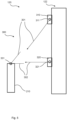
- Fig. 1 shows a schematic representation of a wind turbine 100 for which the solution described here can be used.
- the wind turbine 100 has a tower 102 and a nacelle 104 on the tower 102.
- An aerodynamic rotor 106 with three rotor blades 108 and a spinner 110 is provided on the nacelle 104.
- the aerodynamic rotor 106 is set in rotation by the wind and thus also rotates an electrodynamic rotor or rotor of a generator, which is directly or indirectly coupled to the aerodynamic rotor 106.
- the electrical generator is arranged in the nacelle 104 and generates electrical energy.
- the pitch angles of the rotor blades 108 can be changed by pitch motors at the rotor blade roots of the respective rotor blades 108.
- the tower 120 comprises according to the Figures 2-5 a main tower 122 with a tower base and a tower head.
- a nacelle 104 of a wind turbine 100 can be arranged on the tower head.
- Fig. 2 and 3 Two satellite towers 210, 220 are shown, which are connected to the main tower 122 via a tension and compression-resistant connection 300.
- Fig. 4 Only one satellite tower 210 is shown.
- the satellite towers 210 Figures 4 and 5 However, the principles shown also apply to two or more satellite towers 210, 220.
- the tensile and compressive strength connection 300 between the main tower 122 and the satellite towers 210, 220 comprises a first connection 301 and a second connection 302.
- the first connection 301 is an upwardly extending connection
- the second connection 302 is a substantially horizontal connection.
- the two or more satellite towers 210, 220 can also be connected to one another by a third connection 303 (see Fig. 2 ) must be connected.
- lugs 310, 320 can be provided on the main tower 122 with fastening elements 311, 321 to accommodate the first and second connections 301, 302, which in turn are connected to fastening elements of the satellite towers (in Fig. 5 Fastening element 331 of the satellite tower 210).
- FIG. 6 Another embodiment of a tower 1200 is shown with a main tower 1122 and three satellite towers 1210, 1220, 1230.
- the connection 1300 between the main tower 1122 and the three satellite towers 1210, 1220, 1230 is in the example according to Fig. 6 a direct connection over the entire height of the satellite towers 1210, 1220, 1230 or part thereof.
- the tensile and compressive strength connection 300, 1300 between the main tower 122, 1122 and the at least one satellite tower 210, 220, 1210, 1220, 1230 can absorb tensile and compressive forces at substantially the same level.
- the main tower 122, 1122 and the satellite towers 210, 220, 1210, 1220, 1230 are arranged asymmetrically. Furthermore, the satellite towers 210, 220, 1210, 1220, 1230 are less tall than the main tower 122, 1122. The satellite towers 210, 220, 1210, 1220, 1230 are spaced apart from the main tower 122, 1122 and arranged substantially parallel to the main tower 122, 1122. Finally, the satellite towers 210, 220, 1210, 1220, 1230 are not designed to accommodate a nacelle 104 of a wind turbine 100.
- one, two, several or all of the satellite towers 210, 220, 1210, 1220, 1230 have a storage device and/or are designed as a storage device, for example energy and/or material storage devices.
- Figure 7 shows a schematic flow diagram of an embodiment of a method 1000 for producing a tower 120, 1120 of a wind turbine 100.
- the method 1000 comprises, in a first step 1001, the provision 1001 of a main tower 122, 1122 with a tower base and a tower head, wherein the tower head is designed to receive a nacelle 104 of a wind turbine 100.
- the method 1000 comprises the provision of at least one satellite tower 210, 220, 1210, 1220, 1230.
- the method 1000 comprises the connection 1003 of the at least one satellite tower 210, 220, 1210, 1220, 1230 to the main tower 122 via an access and pressure-resistant connection 300, 1300.
- Figure 8 shows a schematic flow diagram of an embodiment of a method 2000 for producing a wind turbine 100.
- the method 2000 comprises, in a first step, the provision 2001 of a previously described tower 120, 1122.
- the method 2000 comprises the arrangement of a nacelle 104 at the tower head of the main tower 122, 1122.
Landscapes
- Engineering & Computer Science (AREA)
- Life Sciences & Earth Sciences (AREA)
- Sustainable Development (AREA)
- Sustainable Energy (AREA)
- Chemical & Material Sciences (AREA)
- Combustion & Propulsion (AREA)
- Mechanical Engineering (AREA)
- General Engineering & Computer Science (AREA)
- Wind Motors (AREA)
Priority Applications (1)
| Application Number | Priority Date | Filing Date | Title |
|---|---|---|---|
| EP23196953.6A EP4524393A1 (fr) | 2023-09-12 | 2023-09-12 | Tour pour une éolienne, éolienne et procédé de fabrication |
Applications Claiming Priority (1)
| Application Number | Priority Date | Filing Date | Title |
|---|---|---|---|
| EP23196953.6A EP4524393A1 (fr) | 2023-09-12 | 2023-09-12 | Tour pour une éolienne, éolienne et procédé de fabrication |
Publications (1)
| Publication Number | Publication Date |
|---|---|
| EP4524393A1 true EP4524393A1 (fr) | 2025-03-19 |
Family
ID=88017611
Family Applications (1)
| Application Number | Title | Priority Date | Filing Date |
|---|---|---|---|
| EP23196953.6A Pending EP4524393A1 (fr) | 2023-09-12 | 2023-09-12 | Tour pour une éolienne, éolienne et procédé de fabrication |
Country Status (1)
| Country | Link |
|---|---|
| EP (1) | EP4524393A1 (fr) |
Citations (5)
| Publication number | Priority date | Publication date | Assignee | Title |
|---|---|---|---|---|
| US20130233231A1 (en) * | 2010-11-04 | 2013-09-12 | University Of Maine System Board Of Trustees | Floating Wind Turbine Platform and Method of Assembling |
| CN106968502A (zh) * | 2017-05-05 | 2017-07-21 | 河南森源电气股份有限公司 | 通讯基站 |
| US10087915B1 (en) * | 2014-05-20 | 2018-10-02 | Nagan Srinivasan | Self-installing column stabilized offshore wind turbine system and method of installation |
| WO2022103348A1 (fr) * | 2020-11-11 | 2022-05-19 | Ates Celik Insaat Taahhut Proje Muhendislik Sanayi Ve Ticaret Anonim Sirketi | Structure de support à plusieurs pieds pour une tour d'éolienne |
| CN115288506A (zh) * | 2022-08-12 | 2022-11-04 | 中国电信股份有限公司 | 一种通讯基站塔 |
-
2023
- 2023-09-12 EP EP23196953.6A patent/EP4524393A1/fr active Pending
Patent Citations (5)
| Publication number | Priority date | Publication date | Assignee | Title |
|---|---|---|---|---|
| US20130233231A1 (en) * | 2010-11-04 | 2013-09-12 | University Of Maine System Board Of Trustees | Floating Wind Turbine Platform and Method of Assembling |
| US10087915B1 (en) * | 2014-05-20 | 2018-10-02 | Nagan Srinivasan | Self-installing column stabilized offshore wind turbine system and method of installation |
| CN106968502A (zh) * | 2017-05-05 | 2017-07-21 | 河南森源电气股份有限公司 | 通讯基站 |
| WO2022103348A1 (fr) * | 2020-11-11 | 2022-05-19 | Ates Celik Insaat Taahhut Proje Muhendislik Sanayi Ve Ticaret Anonim Sirketi | Structure de support à plusieurs pieds pour une tour d'éolienne |
| CN115288506A (zh) * | 2022-08-12 | 2022-11-04 | 中国电信股份有限公司 | 一种通讯基站塔 |
Similar Documents
| Publication | Publication Date | Title |
|---|---|---|
| EP3092357B1 (fr) | Ensemble comprenant une fondation en béton et une tour et procédé d'érection d'une tour | |
| DE60311894T2 (de) | Turmfundament, insbesondere für eine windenergieturbine | |
| EP3036378B1 (fr) | Socle d'éolienne et éolienne | |
| EP2877654B1 (fr) | Mât modulaire d'une éolienne | |
| EP3092358B2 (fr) | Éolienne pourvue d'un mât et d'une embase composée de plusieurs segments | |
| EP3701107B1 (fr) | Console annulaire destinée à la contrainte externe d'un segment de tour, système de contrainte externe d'une tour hybride, section de tour d'une tour hybride, tour hybride, éolienne et procédé de montage d'un système de contrainte externe pour une tour hybride | |
| EP3710694B1 (fr) | Cadre de bride et ensemble de montage pour le pré-montage et/ou le transport et/ou le montage d'un segment de tour destiné à une éolienne et procede | |
| DE112019007295B4 (de) | Übergangsstück für einen windturbinenturm | |
| EP3477099B1 (fr) | Tour pourvue d'éléments adaptateurs en acier coniques | |
| EP3924577B1 (fr) | Segment de tour hybride, tour hybride pour une éolienne et procédé de fabrication | |
| WO2020161091A1 (fr) | Dispositif et procédé pour détendre un fil de précontrainte | |
| DE102022100725A1 (de) | Turm für eine Windenergieanlage und betreffende Windenergieanlage | |
| EP3891386B1 (fr) | Procédé pour réaliser un préserrage du mât d'une éolienne | |
| DE102006004640B4 (de) | Turm einer Windkraftanlage | |
| DE102019112031A1 (de) | Kabelhalterung für ein Kabel einer Windenergieanlage und Verfahren | |
| EP4524393A1 (fr) | Tour pour une éolienne, éolienne et procédé de fabrication | |
| DE102005047961A1 (de) | Hybridturm | |
| DE102017116873A1 (de) | Windenergieanlagen-Stahlturmringsegment und Verfahren | |
| WO2020212237A1 (fr) | Section de tour et procédé pour la construction d'une tour | |
| EP4118330B1 (fr) | Procédé d'érection d'une centrale éolienne | |
| DE102019218687A1 (de) | Übergangsstück für einen Turm einer Windenergieanlage und Turm einer Windenergieanlage |
Legal Events
| Date | Code | Title | Description |
|---|---|---|---|
| PUAI | Public reference made under article 153(3) epc to a published international application that has entered the european phase |
Free format text: ORIGINAL CODE: 0009012 |
|
| STAA | Information on the status of an ep patent application or granted ep patent |
Free format text: STATUS: THE APPLICATION HAS BEEN PUBLISHED |
|
| AK | Designated contracting states |
Kind code of ref document: A1 Designated state(s): AL AT BE BG CH CY CZ DE DK EE ES FI FR GB GR HR HU IE IS IT LI LT LU LV MC ME MK MT NL NO PL PT RO RS SE SI SK SM TR |
|
| STAA | Information on the status of an ep patent application or granted ep patent |
Free format text: STATUS: REQUEST FOR EXAMINATION WAS MADE |
|
| 17P | Request for examination filed |
Effective date: 20250722 |
|
| STAA | Information on the status of an ep patent application or granted ep patent |
Free format text: STATUS: EXAMINATION IS IN PROGRESS |
|
| 17Q | First examination report despatched |
Effective date: 20250911 |