EP4528032A1 - Verriegelungskinematik für ein kanalblech eines strassenfertigers - Google Patents
Verriegelungskinematik für ein kanalblech eines strassenfertigers Download PDFInfo
- Publication number
- EP4528032A1 EP4528032A1 EP23198261.2A EP23198261A EP4528032A1 EP 4528032 A1 EP4528032 A1 EP 4528032A1 EP 23198261 A EP23198261 A EP 23198261A EP 4528032 A1 EP4528032 A1 EP 4528032A1
- Authority
- EP
- European Patent Office
- Prior art keywords
- channel plate
- locking
- latch
- locking position
- stop
- Prior art date
- Legal status (The legal status is an assumption and is not a legal conclusion. Google has not performed a legal analysis and makes no representation as to the accuracy of the status listed.)
- Pending
Links
Images


Classifications
-
- E—FIXED CONSTRUCTIONS
- E01—CONSTRUCTION OF ROADS, RAILWAYS, OR BRIDGES
- E01C—CONSTRUCTION OF, OR SURFACES FOR, ROADS, SPORTS GROUNDS, OR THE LIKE; MACHINES OR AUXILIARY TOOLS FOR CONSTRUCTION OR REPAIR
- E01C19/00—Machines, tools or auxiliary devices for preparing or distributing paving materials, for working the placed materials, or for forming, consolidating, or finishing the paving
- E01C19/48—Machines, tools or auxiliary devices for preparing or distributing paving materials, for working the placed materials, or for forming, consolidating, or finishing the paving for laying-down the materials and consolidating them, or finishing the surface, e.g. slip forms therefor, forming kerbs or gutters in a continuous operation in situ
-
- E—FIXED CONSTRUCTIONS
- E01—CONSTRUCTION OF ROADS, RAILWAYS, OR BRIDGES
- E01C—CONSTRUCTION OF, OR SURFACES FOR, ROADS, SPORTS GROUNDS, OR THE LIKE; MACHINES OR AUXILIARY TOOLS FOR CONSTRUCTION OR REPAIR
- E01C2301/00—Machine characteristics, parts or accessories not otherwise provided for
- E01C2301/14—Extendable screeds
- E01C2301/16—Laterally slidable screeds
Definitions
- the present invention relates to the technical field of road pavers.
- the invention relates to road pavers with a channel plate arrangement, a locking kinematics for such a channel plate arrangement, and a method for pivoting a channel plate of a road paver.
- Road pavers are well known from the state of the art. To increase their usability, screeds with variable working widths were designed.
- the working width is the width with which the screed distributes the paving material on the subsoil.
- EP 2 169 117 A1 For example, it reveals a paving screed with a continuously variable working width.
- the paving material is distributed by a spreading auger in front of the screed, perpendicular to the paving direction of the road paver.
- Adjusting the working width of the screed also changes the width of the applied paving material.
- the width of the channel plate assembly can also be optionally adjusted to the working width. This can be achieved, for example, by using laterally pivoting plates on the outer sides of the channel plate assembly.
- a channel plate arrangement for a road paver with pivoting channel plates is known.
- the channel plates are pivoted and held in position by means of a hydraulic pivoting device.
- the object of the present invention is to provide a compact and secure locking device for pivotable components, in particular pivotable channel plates of a road paver.
- a first aspect of the invention relates to a channel plate arrangement for a road paver.
- the channel plate arrangement comprises a channel plate and a pivoting device.
- the channel plate arrangement can also comprise further channel plates.
- the channel plate is attached to a component of the road paver, in particular to a component of the channel plate arrangement, by means of the pivoting device.
- the channel plate is rotatable about the pivoting device.
- the pivoting device can enable rotation of the channel plate about a vertical axis.
- the channel plate can be pivoted horizontally.
- the channel plate is rotatable between a minimum channel plate position and a maximum channel plate position.
- the channel plate arrangement can further comprise a locking device.
- the locking device is configured to assume a first locking position and a second locking position. In the first locking position, the locking device is configured to block the rotation of the channel plate about the pivoting device when the channel plate is in a first channel plate position, in the direction of the minimum channel plate position. In the second locking position, the locking device is configured to block the rotation of the channel plate about the pivoting device when the channel plate is in a second channel plate position, in the direction of the maximum channel plate position.
- the width of the channel plate arrangement can be varied.
- the minimum channel plate position can correspond to the smallest width of the channel plate arrangement.
- the maximum channel plate position can correspond to the maximum width of the channel plate arrangement. In the minimum channel plate position, the channel plate can rest against the road paver. In the maximum channel plate position, the channel plate can protrude from the road paver, particularly orthogonally.
- the road paver moves in a paving direction while paving the paving material.
- the channel plate In the minimum channel plate position, the channel plate can extend parallel to the paving direction.
- the pivoting device can then be arranged at a front end of the channel plate, relative to the paving direction.
- the channel plate In the minimum channel plate position, the channel plate can be pivoted backward, opposite to the paving direction.
- the channel plate In the maximum channel plate position, the channel plate can extend orthogonally to the paving direction.
- the first channel plate position may be closer to the maximum channel plate position than the second channel plate position.
- the first channel plate position may correspond to the maximum channel plate position.
- the second channel plate position may correspond to the minimum channel plate position or a channel plate position between the minimum and maximum channel plate positions.
- the first locking position of the locking device may differ from the second locking position.
- the locking device can be designed to fix the channel plate in the first channel plate position, in particular in the maximum channel plate position, in the first locking position.
- the locking device can be designed to fix the channel plate in the second channel plate position, in particular in the minimum channel plate position, in the second locking position.
- the locking device can be configured to assume a third locking position.
- the locking device can be configured to block, in the third locking position, the rotation of the channel plate around the pivoting device when the channel plate is in a third channel plate position, in the direction of the maximum channel plate position.
- the second channel plate position can be between the minimum channel plate position and the maximum channel plate position.
- the second channel plate position can be between the first channel plate position and the third channel plate position.
- the first channel plate position can correspond to the maximum channel plate position.
- the third channel plate position can correspond to the minimum channel plate position.
- the locking device can be designed to fix the channel plate in the third channel plate position, in particular in the minimum channel plate position, in the third locking position.
- the locking device can be designed to block, in the second locking position, the rotation of the channel plate about the pivoting device when the channel plate is in a fourth channel plate position, in the direction of the minimum channel plate position.
- the fourth channel plate position may be between the second and third channel plate positions.
- the fourth channel plate position may correspond to the third channel plate position.
- the locking device can be configured to limit the rotation of the channel plate around the pivoting device to an angular range in the second locking position.
- the angular range can essentially span an angle of 60 degrees.
- the angular range can represent the range between 0 and 60 degrees, or 120 and 180 degrees, relative to the installation direction of travel.
- the channel plate In the first channel plate position, the channel plate can have a first angle to the paving direction of travel of the road paver.
- the channel plate can be rotatable between a second angle and a third angle to the paving direction of travel of the road paver when the locking device is in the second locking position.
- the channel plate In the third channel plate position, the channel plate can have the third angle to the paving direction of travel of the road paver.
- the second angle can be between the first angle and the third angle.
- the first angle can be substantially 80 to 100 degrees, in particular 90 degrees, relative to the installation direction.
- the second angle can be substantially 50 to 70 degrees, in particular 60 degrees, or 110 to 130 degrees, in particular 120 degrees, relative to the installation direction.
- the second angle can be inclined backward relative to the installation direction.
- the third angle can be substantially 0 to 10 degrees, in particular 0 degrees, or 170 to 180 degrees, in particular 180 degrees, relative to the installation direction of travel.
- the third angle can be inclined backward relative to the installation direction of travel.
- the locking device may comprise a latch configured to assume the first locking position and the second locking position.
- the latch may be configured to assume the third locking position.
- the locking device may comprise a latch configured to assume the first locking position, the second locking position, and the third locking position.
- the locking device may comprise a latch configured to assume the second locking position and the third locking position.
- the locking device may comprise a latch configured to assume the first locking position and the third locking position.
- the latch may additionally assume an unlocking position.
- the latch can be connected to the channel plate.
- the latch In the first locking position, when the channel plate is in the first channel plate position, the latch can rest with a first surface against a stop of the road paver, in particular against a stop of the pivoting device. This can prevent rotation of the channel plate in the direction of the minimum channel plate position by the latch.
- the latch In the second locking position, when the channel plate is in the second channel plate position, the latch can rest with a second surface against a stop of the road paver, in particular against a stop of the pivoting device. This can prevent rotation of the channel plate in the direction of the maximum channel plate position by the latch.
- stop may refer to a component or surface that can be brought into contact with the latch and thereby restricts the movement of the latch in at least one direction.
- the latch can be configured to assume the third locking position. In the third locking position, when the channel plate is in the third channel plate position, the latch can abut with a third surface against a stop of the road paver, in particular against a stop of the pivoting device. This can prevent rotation of the channel plate in the direction of the maximum channel plate position by the latch.
- the latch can be connected to the channel plate directly or via at least one intermediate piece.
- the latch can be rotatable together with the channel plate around the pivoting device.
- a channel plate projection can be attached to the channel plate.
- the channel plate projection can form a stop for the latch.
- the latch In the first locking position, the latch can abut against the stop of the channel plate projection with a surface facing away from the channel plate.
- the latch In the third locking position, the latch can abut against the stop of the channel plate projection with a surface facing away from the channel plate.
- the latch In the first and third locking positions, the latch can abut against the same stop of the channel plate projection with the same surface facing away from the channel plate.
- the latch can have a projection in the direction of its thickness.
- the latch In the second locking position, the latch can abut against a stop of the channel plate projection with a further surface, in particular a surface of the latch projection facing away from the pivoting device.
- the latch can be connected to a component of the road paver, in particular the pivoting device.
- the latch In the first locking position, when the channel plate is in the first channel plate position, the latch can abut with a first surface against a stop of the channel plate. This can prevent rotation of the channel plate in the direction of the minimum channel plate position by the latch.
- the latch In the second locking position, when the channel plate is in the second channel plate position, the latch can abut with a second surface against a stop of the channel plate. This can prevent rotation of the channel plate in the direction of the maximum channel plate position by the latch.
- the latch In the third locking position, when the channel plate is in the third channel plate position, the latch can rest with a third surface against a stop of the channel plate. This can prevent the latch from rotating the channel plate toward the maximum channel plate position.
- the locking device can be configured to assume an unlocking position.
- the channel plate can be freely rotatable about the pivoting device between the minimum channel plate position and the maximum channel plate position when the locking device is in the unlocking position.
- the latch can be held in the first, second, and/or third locking position by its own weight.
- the latch can be held in the first and second locking positions by its own weight.
- the latch can be held in the unlocked position by its own weight.
- the third locking position may be different from the first locking position and the second locking position.
- the channel plate arrangement may comprise a further channel plate which is not pivotable.
- the non-pivoting channel plate may be laterally displaceable
- the channel plate arrangement can have two additional channel plates that are not pivotable.
- the pivoting device can be attached to the paver.
- the pivoting device can be attached to the non-pivoting channel plate.
- the pivoting device can be attached to the non-pivoting, movable channel plate.
- the pivoting device can be designed as a hinge.
- the pivoting device can enable rotation of the channel plate about a vertical axis.
- the pivoting device can consist of a first cylinder and a second cylinder.
- the two cylinders can extend in the vertical direction.
- the second cylinder can be a hollow cylinder.
- the first cylinder can be arranged in the hollow cylinder.
- the two cylinders can be designed such that they are rotatable relative to one another.
- the first cylinder or the second cylinder can be connected to the channel plate.
- the other cylinder of the first or second cylinder can be connected to a component of the road paver, in particular a component of the channel plate arrangement, in particular a non-pivoting channel plate of the channel plate arrangement.
- the first cylinder and the second cylinder enable rotation of the channel plate relative to the rest of the channel plate arrangement.
- the road paver may have a hydraulic cylinder configured to retract and extend the channel plate arrangement.
- the road paver may have a hydraulic cylinder configured to rotate the channel plate about the pivoting device.
- the road paver may have an electric drive configured to rotate the channel plate about the pivoting device.
- the rotation of the channel plate about the pivoting device can be done manually.
- the rotation of the channel plate about the pivoting device can be caused by the paving material, in particular when the paving material is conveyed by the transverse distribution device towards the channel plate.
- the latch can be subjected to bending in the first locking position. This can block the rotation of the channel plate towards the minimum channel plate position.
- the latch can be subjected to bending in the third locking position. This can block the rotation of the channel plate towards the maximum channel plate position.
- the latch can be subjected to compression in the second locking position. This can block the rotation of the channel plate towards the maximum channel plate position.
- the latch may be designed according to the latch described in the third aspect of the invention.
- the latch may be a first latch.
- the locking device may comprise a second latch.
- the second latch can be designed the same as the first latch.
- the second latch can be designed according to the latch described in the third aspect of the invention.
- the second latch can be arranged vertically below the first latch.
- the second latch can be arranged vertically above the first latch.
- the second latch can be designed to assume the second and third locking positions, in particular simultaneously with the first latch.
- the second latch can be designed to assume the first, second and third locking positions, in particular simultaneously with the first latch.
- the road paver in particular the pivoting device, can have a second stop.
- the second stop can interact with the second bar.
- the second bar can be connected to the channel plate.
- the second latch In the first locking position of the second latch, when the channel plate is in the first channel plate position, the second latch can abut against the second stop with a first surface. This can prevent rotation of the channel plate toward the minimum channel plate position by the second latch.
- the latch In the second locking position of the second latch, when the channel plate is in the second channel plate position, the latch can abut against the second stop with a second surface. This can prevent rotation of the channel plate toward the maximum channel plate position by the second latch.
- the latch In the third locking position of the second latch, when the channel plate is in the third channel plate position, the latch can abut against the second stop with a third surface. This can prevent rotation of the channel plate toward the maximum channel plate position by the second latch.
- the second latch can be configured to assume only the second and third locking positions.
- the second latch can be configured to assume an unlocking position.
- the second stop can be configured such that the second latch can only assume the second and third locking positions.
- the first latch may have an elongated hole.
- the first latch may be attached to the channel plate by means of a fastening means, in particular a screw or a bolt, through the elongated hole.
- the second latch may have an elongated hole.
- the second latch may be attached to the channel plate by means of a fastening means, in particular a screw or a bolt, through the elongated hole.
- the channel plate assembly may comprise a control device.
- the control device may be configured to rotate the channel plate about the pivoting device.
- the control device may be configured to move the channel plate to the first, second and/or third channel plate position.
- the control device may be configured to To move the latch into the unlocking position.
- the control device can be configured to move the latch into the first, second, and/or third locking position.
- a second aspect of the invention relates to a road paver comprising a screed assembly.
- the road paver can move along a paving direction of travel while paving paving material.
- the screed assembly can be designed to be variable in width.
- the width of the screed assembly can refer to the extent of the screed assembly orthogonal to the paving direction of travel.
- the road paver comprises a transverse distribution device.
- the transverse distribution device can be designed to distribute paving material transversely to the paving direction of travel.
- the transverse distribution device can be a conveyor screw.
- the road paver has a first channel plate assembly.
- the first channel plate assembly can be designed according to the first aspect of the invention.
- the first channel plate assembly is arranged in front of the transverse distribution device in the paving direction of travel.
- the transverse distribution device is arranged in front of the screed assembly in the paving direction of travel.
- the first channel plate arrangement can be arranged on a first side of the road paver, for example, on the left side as viewed in the paving direction.
- the road paver can have a second channel plate arrangement.
- the second channel plate arrangement can be designed according to the first aspect of the invention.
- the second channel plate arrangement can be arranged on a second side opposite the first side, for example, on the right side as viewed in the paving direction.
- the first channel plate arrangement and the second channel plate arrangement can form a channel plate device.
- the channel plate device can additionally have a further channel plate that is not pivotable.
- the channel plate device can additionally have two further channel plates that are not pivotable.
- the channel plate device can have hydraulic cylinders that are designed to pivot the pivotable channel plates of the first channel plate arrangement and the second channel plate arrangement.
- the channel plate device can have electric drives that are designed to pivot the pivotable channel plates of the first channel plate arrangement and the second channel plate arrangement.
- the road paver may include a control device.
- the control device may be configured to rotate the channel plate about the pivoting device.
- the control device may be configured to move the channel plate to the first, second, and/or third channel plate position.
- the control device may be configured to move the latch to the unlocking position.
- the control device may be configured to move the latch to the first, second, and/or third locking position.
- a third aspect of the invention relates to locking kinematics for a pivotable component of a construction machine, in particular for a channel plate arrangement according to the first aspect of the invention.
- the locking kinematics comprises at least one locking component.
- the locking component has a first stop, a second stop, and a third stop.
- the stops can be designed as surfaces.
- the locking kinematics further comprises at least one latch, which extends substantially along an axial direction between a first distal end and a second distal end.
- the latch can have an elongated hole.
- the elongated hole can extend in the axial direction of the latch, in particular can be arranged parallel to the axial direction.
- the latch can be rotatably attached to the pivotable component by means of a fastening means, in particular a screw or a bolt, through the elongated hole.
- the fastening means can be movable within the elongated hole.
- the latch can be displaceable relative to the pivotable component.
- the latch can have a projection in the thickness direction at a first distal end.
- the thickness direction can extend orthogonally to the axial direction.
- the bar can be L-shaped.
- the projection can represent one leg of the L-shape.
- the other leg of the L-shape can be formed by the extension of the bar in the axial direction.
- the projection can have a beveled surface on the side facing away from the second distal end.
- the latch can be moved to a first locking position.
- the latch can be moved to a second locking position.
- the latch can be moved to a third locking position.
- a surface of the projection facing the second distal end of the latch can abut the first stop.
- the beveled surface of the projection can abut the second stop.
- a surface of the projection facing the pivotable component can abut the third stop.
- the first locking position can be different from the second and/or third locking position.
- the second locking position can be different from the first and/or third locking position.
- the beveled surface of the projection may extend at an angle, in particular an angle between 50 and 70 degrees, in particular an angle of 60 degrees, to the axial direction of the bolt.
- the beveled surface of the projection may extend at an angle, in particular an angle between 20 and 40 degrees, in particular an angle of 30 degrees, to the thickness direction of the bolt.
- the second stop and the third stop can represent the same stop.
- the second stop and the third stop can be formed by the same surface.
- the locking component may be attached to a pivoting device.
- the pivotable component may be secured to the pivoting device.
- the pivotable component may be rotatable about the pivoting device.
- the locking component may be configured such that it is not rotatable about the pivoting device.
- the pivotable member When the latch is in the first locking position, the pivotable member can be movable between a first pivot angle and a second pivot angle. When the latch is in the second locking position, the pivotable member can be movable between a third pivot angle and a fourth pivot angle. When the latch is in the third locking position, the pivotable member can be movable between the fourth pivot angle and a fifth pivot angle.
- the first pivot angle can correspond to a maximum pivot position.
- the pivot device or the construction machine can be designed such that the pivotable component cannot be pivoted further than the maximum pivot position.
- the fifth pivot angle can correspond to a minimum pivot position.
- the pivot device or the construction machine can be designed such that the pivotable component cannot be pivoted further than the minimum pivot position.
- the pivot device or the construction machine can be designed such that the pivotable component can be pivoted between the minimum pivot position and the maximum pivot position.
- the first pivot angle can be identical to the second pivot angle.
- the pivotable component can be fixed at the position of the first pivot angle or the second pivot angle, in particular the maximum pivot position.
- the fourth pivot angle can be identical to the fifth pivot angle.
- the pivotable component can be fixed at the position of the fourth pivot angle or the fifth pivot angle, in particular the minimum pivot position.
- the fastening means When the latch is in the first locking position, the fastening means may be located at an end of the elongated hole facing the second distal end of the latch. When the latch is in the second locking position, the fastening means may be located at an end of the elongated hole facing the first distal end of the latch. When the latch is in the third locking position, the fastening means may be located at an end of the elongated hole facing the second distal end of the latch. When When the latch is in the unlocking position, the fastener may be located at one end of the elongated hole facing the second distal end of the latch.
- the latch may represent a first latch.
- the locking mechanism may include a second latch.
- the second latch may be identical to the first latch.
- the locking component may represent a first locking component.
- the locking kinematics may include a second locking component.
- the second locking component may be attached to the pivoting device.
- the second locking component may be configured such that it is not rotatable about the pivoting device.
- the second locking component has a first stop, a second stop, and a third stop. Alternatively, the second locking component may have only one stop.
- the second locking component may be formed integrally with the first locking component.
- the second latch can be moved into a first, second, and third locking position.
- the second latch can be moved into an unlocking position.
- a surface of the projection of the second latch facing the second distal end of the second latch can abut the first stop of the second locking component.
- the beveled surface of the projection of the second latch can abut the second stop of the second locking component.
- a surface of the projection of the second latch facing the pivotable component can abut the third stop of the second locking component.
- the second latch can only be moved to the second and third locking positions and the unlocking position.
- the beveled surface of the projection of the second latch can abut the stop of the second locking component.
- a surface of the projection of the second latch facing the pivotable component can abut the stop of the second locking component.
- a projection can be attached to the pivotable component.
- the projection can form a stop for the bolt.
- the projection can be L-shaped.
- the bolt In the first locking position, the bolt can rest against the stop of the projection with a surface facing away from the pivotable component.
- the third locking position the bolt can rest against the stop of the projection with a surface facing away from the pivotable component. the stop of the projection.
- the latch In the first and third locking positions, the latch can abut against the same stop of the projection with the same surface facing away from the pivotable component.
- the latch In the second locking position, the latch can abut against a stop of the projection of the pivotable component with a further surface, in particular a surface of the latch projection facing the second distal end.
- a road paver in particular the road paver according to the second aspect of the invention, comprises a screed assembly.
- the road paver can move along a paving direction of travel during the paving of paving material.
- the road paver comprises a transverse distribution device, in particular a conveyor screw.
- the road paver has a pivotable component.
- the pivotable component is arranged in front of the transverse distribution device in the paving direction of travel.
- the road paver comprises the locking kinematics according to the third aspect of the invention.
- the locking kinematics can be designed to fix the pivotable component in different positions or to limit the rotation of the pivotable component.
- the locking kinematics may include a control device.
- the control device may be configured to rotate the pivotable component.
- the control device may be configured to move the latch into the unlocking position.
- the control device may be configured to move the latch into the first, second, and/or third locking position.
- a fourth aspect of the invention relates to the use of a locking kinematics according to the third aspect of the invention for locking a channel plate arrangement according to the first aspect of the invention.
- a fifth aspect of the invention relates to a method for pivoting a channel plate of a road paver.
- the method comprises moving a locking device of the road paver into an unlocking position.
- the channel plate is pivotable between a minimum channel plate position and a maximum channel plate position, in particular about a vertical axis.
- the method further comprises pivoting the channel plate into a channel plate position located between the minimum channel plate position and the maximum channel plate position.
- the method further comprises moving the locking device into a locking position. In the locking position, the channel plate is pivotable between the minimum channel plate position and a middle channel plate position.
- the middle channel plate position is located between the minimum channel plate position and the maximum channel plate position.
- the middle channel plate position may be closer to the maximum channel plate position than to the minimum channel plate position.
- the method may further comprise moving the locking device into the unlocking position and then pivoting the channel plate into the minimum or maximum channel plate position.
- the locking device may then be moved into a further locking position, which differs in particular from the other locking position.
- the channel plate may be fixed in the minimum channel plate position or the maximum channel plate position, respectively.
- the pivoting of the channel plate into the channel plate position, the minimum channel plate position, the middle channel plate position, and/or the maximum channel plate position can be accomplished by means of a hydraulic cylinder and/or electric drive.
- the pivoting of the channel plate into the channel plate position, the minimum channel plate position, the middle channel plate position, and/or the maximum channel plate position can be accomplished by a control unit.
- the locking device can be moved to the unlocking position manually.
- the locking device can be moved to the locking position manually.
- the locking device can be moved to the further locking position manually.
- the channel plate arrangement according to the first aspect of the invention can be used in a road paver according to the second aspect of the invention and/or with method steps of the method according to the fifth aspect of the invention.
- the channel plate arrangement according to the first aspect of the invention can be used in combination with the locking kinematics according to the third aspect of the invention.
- the channel plate arrangement according to the first aspect of the invention and the locking kinematics according to the third aspect of the invention can be used after use according to the fourth aspect of the invention.
- the locking kinematics according to the third aspect of the invention can be used in a road paver according to the second aspect of the invention and/or with method steps of the method according to the fifth aspect of the invention.
- a locking kinematics according to the fourth aspect of the invention can be carried out with a locking kinematics according to the third aspect of the invention, in a road paver according to the second aspect of the invention and/or using method steps of the method according to the fifth aspect of the invention.
- the method according to the fifth aspect of the invention can be carried out with a Channel plate arrangement according to the first aspect of the invention, with a road paver according to the second aspect of the invention and/or a locking kinematics according to the third aspect of the invention.
- first,” “second,” “third,” and “fourth” are merely designations for a specific element or component and do not necessarily imply a particular order of the components or elements mentioned. For example, the presence of a second component does not necessarily imply the presence of a first component, and vice versa.
- Fig. 1 shows a road paver 1 according to an embodiment of the invention.
- the road paver 1 comprises a towing vehicle 2 and a screed assembly 3.
- the screed assembly 3 is arranged behind the towing vehicle 2 with respect to the paving direction 100.
- the screed assembly 3 is in Fig. 1 only schematically sketched.
- a material hopper 4 is arranged for receiving paving material.
- the paving material also referred to as paving material, is transported rearward by a material transport device of the towing vehicle 2 against the paving direction 100 and presented to the paving screed assembly 3.
- a transverse distribution device 5 is provided on the towing vehicle 2, which distributes the paving material orthogonally to the paving direction 100 in front of the screed assembly 3.
- a channel plate device 6 with at least one channel plate assembly 7 is arranged in the paving direction 100 in front of the transverse distribution device 5. The channel plate device 6 prevents the paving material from deflecting in the direction of paving direction 100.
- Fig. 2 shows a plan view of a road paver 1 according to an embodiment of the invention.
- the screed assembly 3 comprises a base screed 8.
- the base screed has a base screed working width 201.
- the base screed working width 201 can be the extension of the base screed 8 in the transverse direction 200.
- the transverse direction 200 extends orthogonally to the paving direction 100.
- the screed assembly 3 can additionally have extending screeds 9.
- the total working width 202 is composed of the base screed 8 and the extending screeds 9.
- the extending screeds 9 can be designed to be movable relative to the base screed 8 in the transverse direction 200. As a result, the total working width 202 can be varied.
- the screed assembly 3 can furthermore have side shields 10.
- the side shields 10 extend in particular in the paving direction 100 and prevent the paving material from being distributed into areas that lie laterally outside the paving screed arrangement 3.
- the transverse distribution device 5 is arranged in front of the screed assembly 3 in the paving direction 100.
- the channel plate device 6 is arranged in front of the transverse distribution device 5 in the paving direction 100.
- the channel plate device 6 has a channel plate assembly 7.
- the channel plate assembly 7 has a pivotable channel plate 11.
- the channel plate 11 is rotatable about a pivoting device 12, in particular about a vertical axis.
- the channel plate device 6 can have a base channel plate 13.
- the base channel plate 13 extends substantially in the transverse direction 200.
- the channel plate device 6 can additionally have an extendable channel plate 14.
- the extendable channel plate 14 can be moved in the transverse direction 200 relative to the base channel plate 13 by means of a displacement device 15, for example a hydraulic cylinder or an electric drive.
- the laterally extendable channel plate 14 allows the effective width of the channel plate device 6 to be varied.
- the channel plate device 6 can have an intermediate channel plate 16.
- the intermediate channel plate 16 can be arranged between the base channel plate 13 and the extendable channel plate 14.
- the extendable channel plate 14 can be fastened to the base channel plate 13 or the intermediate channel plate 16.
- the displacement device 15 can be fastened to the base channel plate 13 or the intermediate channel plate 16.
- the pivoting device 12 can be attached to the base channel plate 13, the extendable channel plate 14, or the intermediate channel plate 16.
- the pivoting channel plate 11 can thus be rotated relative to the base channel plate 13, the extendable channel plate 14, or the intermediate channel plate 16.
- the channel plate device 6 can have two channel plate arrangements 7, as in Fig. 2
- the two channel plate arrangements 7 can advantageously be arranged on the left and right sides of the road finisher 1.
- the channel plate device 6 can have two extendable channel plates 14, two travel devices 15 and two intermediate channel plates 16, as in Fig. 2 shown. These can advantageously be arranged on the left and right sides of the road paver 1.
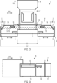
- Fig. 3 shows a front view of the channel plate device 6 from Fig. 2
- the channel plate device 6 comprises the base channel plate 13, to which the intermediate channel plate 16 is attached laterally in the transverse direction 200.
- the displacement device 15 is attached to the intermediate channel plate 16 and is designed to move the extendable channel plate 14 adjacent to the intermediate channel plate 16 in the transverse direction 200.
- the pivotable channel plate 11 is attached to the extendable channel plate 14 by means of the pivoting device 12.
- the pivoting device 12 is designed to enable rotation of the pivotable channel plate 11 about a vertical axis.
- Fig. 4 shows a schematic top view of a channel plate assembly 7 according to an embodiment of the invention.
- the channel plate assembly 7 is attached directly to the base channel plate 13.
- the pivotable channel plate 11 is fastened to the base channel plate 13 by means of the pivoting device 12.
- the pivotable channel plate 11 can be rotated about the pivoting device 12 between a minimum channel plate position 17 and a maximum channel plate position 18.
- Fig. 4 shows the pivotable channel plate 11 in a first channel plate position 19, a second channel plate position 20 and a third channel plate position 21.
- the first channel plate position 19 corresponds to the maximum channel plate position 18.
- the third channel plate position 21 corresponds to the minimum channel plate position 17.
- the channel plate 11 has a first angle 22 to the paving direction 100.
- the first angle 22 can be 90 degrees.
- the channel plate 11 has a second angle 23 to the paving direction 100.
- the second angle 23 can be 120 degrees.
- the channel plate 11 has a third angle 24 to the paving direction 100.
- the third angle 24 can be 180 degrees.
- the channel plate 11 can run parallel to the paving direction 100.
- the channel plate assembly 7 further comprises a locking device 25 with a first latch 26.
- the locking device 25 may additionally comprise a second latch 27.
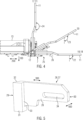
- the first bar 26 is in Fig. 5 shown in a detailed view.
- the latch 26 has a latch base body 28 which extends substantially along an axial direction 300 between a first distal end 29 and a second distal end 30.
- the material thickness of the latch 26 is measured in the thickness direction 400.
- the thickness direction 400 of the latch 26 is the direction in which the latch 26 has the smallest extension.
- the latch 26 has a projection 31 in the thickness direction 400 at the first distal end 29.
- the material thickness of the projection 31 is greater than the material thickness of the latch base body 28.
- the projection 31 has a beveled surface 32 on the side facing away from the second distal end 30.
- the beveled surface 32 runs at an angle to the axial direction 300, wherein the angle differs from 90 degrees.
- the beveled surface 32 extends at an angle to the thickness direction 400.
- the surface 33 of the projection 31 facing the second distal end 30 extends orthogonally to the axial direction 300.
- the latch 26 further has an elongated hole 34.
- the elongated hole 34 is arranged in the latch base body 28 and can extend in the axial direction 300.
- the second latch 27 can be configured identically to the first latch 26.
- the Fig. 6 to 9 show detailed views of a locking device 25 according to an embodiment of the invention in the unlocking position and three locking positions.
- the first latch 26 and the second latch 27 are each connected to the pivotable channel plate 11 by means of a screw 35 that is guided through the elongated hole 34.
- the latches 26, 27 are not connected directly to the channel plate 11, but indirectly via an intermediate piece 36 each.
- the intermediate pieces 36 can be welded to the channel plate 11.
- the intermediate pieces 36 are connected to a component of the pivoting device 12, for example, welded to it.
- the component and thus the channel plate 11 is rotatable about the rest of the pivoting device 12.
- the channel plate 11 additionally has two channel plate projections 37, which are connected to the channel plate 11, for example, welded to it, and are each arranged below the intermediate pieces 36.
- the locking device 25 further comprises a first locking component 38.
- the first locking component 38 has a first stop 39, a second stop 40, and a third stop 41.
- the second stop 40 and the third stop 41 may be the same stop.
- the term stop may refer to a component or a surface that can be brought into contact with the latch 26 and thereby restricts the movement of the latch 26 in at least one direction.
- Locking device 25 further comprises a second locking component 42.
- the second locking component 42 has a stop 43.
- the first locking component 38 can be formed integrally with the second locking component 42.
- the first locking component 38 and the second locking component 42 are connected to the pivoting device 12.
- the first locking component 38 and the second locking component 42 do not rotate about the pivoting device 12.
- Fig. 6 shows the locking device 25 in the unlocked position.
- the two latches 26, 27 can be in a position folded away from the pivoting device 12.
- the two latches 26, 27 can rest on the respective channel plate projection 37.
- the two latches 26, 27 are held in the unlocked position by their own weight.
- the screws 35 are arranged at the end of the respective elongated hole 34 of the first and second latches 26, 27 that faces the second distal end 30.
- the channel plate 11 can be rotated around the pivoting device 12 between the minimum channel plate position 17 and the maximum channel plate position 18.
- Fig. 7 shows the locking device 25 in the first locking position.
- the channel plate 11 is located in the first channel plate position 19.
- the first latch 26 is folded towards the pivoting device 12.
- the surface 33 of the projection 31 of the first latch 26 facing the second distal end 30 bears against the first stop 39 of the first locking component 38.
- the first stop 39 has a surface that runs at an angle to a horizontal plane and at an angle to a vertical plane. The interaction between the first latch 26 and the first locking component 38 blocks the rotation of the channel plate 11 in the direction of the minimum channel plate position 17.
- the second bar 27 is located at the Fig. 7 shown embodiment in the unlocked position.
- the screw 35 of the first latch 26 is arranged at the end of the elongated hole 34 of the first latch 26 that faces the second distal end 30 of the first latch 26.
- the screw 35 of the second latch 27 is arranged at the end of the elongated hole 34 of the second latch 27 that faces the second distal end 30 of the second latch 27.
- the second latch 27 can also be in the first locking position.
- the second locking component 42 is configured identically to the first locking component 38.
- Fig. 8 shows the locking device 25 in the second locking position.
- the channel plate 11 is in the second channel plate position 20.
- the two latches 26, 27 are folded toward the pivoting device 12.
- the screw 35 of the first latch 26 is arranged at the end of the elongated hole 34 of the first latch 26 that faces the first distal end 29 of the first latch 26.
- the screw 35 of the second latch 27 is arranged at the end of the elongated hole 34 of the second latch 27 that faces the first distal end 29 of the second latch 27.
- the beveled surface 32 of the first latch 26 abuts the second stop 40 of the first locking component 38.
- the surface 33 of the projection 31 of the first latch 26 facing the second distal end 30 can abut the channel plate projection 37 associated with the first latch 26.
- the beveled surface 32 of the second latch 27 abuts the stop 43 of the second locking component 42.
- the surface 33 of the projection 31 of the second latch 27 facing the second distal end 30 can abut the channel plate projection 37 associated with the second latch 27.
- the interaction between the first latch 26 and the first locking component 38 and, if applicable, the channel plate projection 37 blocks the rotation of the channel plate 11 in the direction of the maximum channel plate position 18.
- the interaction between the second latch 27 and the second locking component 42 and, if applicable, the channel plate projection 37 blocks the rotation of the channel plate 11 in the direction of the maximum channel plate position 18.
- Fig. 9 shows the locking device 25 in the third locking position.
- the channel plate 11 is in the third channel plate position 21.
- the two latches 26, 27 are folded toward the pivoting device 12.
- the screw 35 of the first latch 26 is arranged at the end of the elongated hole 34 of the first latch 26 that faces the second distal end 30 of the first latch 26.
- the screw 35 of the second latch 27 is arranged at the end of the elongated hole 34 of the second latch 27 that faces the second distal end 30 of the second latch 27.
- a surface of the first latch 26 facing the channel plate 11 abuts the third stop 41 of the first locking component 38.
- a surface of the first latch 26 facing away from the channel plate 11 can abut the channel plate projection 37 associated with the first latch 26.
- a surface of the second latch 27 facing the channel plate 11 abuts the stop 43 of the second locking component 42.
- a surface of the second latch 27 facing away from the channel plate 11 can abut the channel plate projection 37 associated with the second latch 27.
- the interaction between the first latch 26 and the first locking component 38 and, if applicable, the channel plate projection 37 blocks the rotation of the channel plate 11 in the direction of the maximum channel plate position 18.
- the interaction between the second latch 27 and the second locking component 42 and, if applicable, the channel plate projection 37 blocks the rotation of the channel plate 11 in the direction of the maximum channel plate position 18.
Landscapes
- Engineering & Computer Science (AREA)
- Architecture (AREA)
- Civil Engineering (AREA)
- Structural Engineering (AREA)
- Road Paving Machines (AREA)
Abstract
Description
- Die vorliegende Erfindung betrifft das technische Gebiet der Straßenfertiger. Insbesondere betrifft die Erfindung Straßenfertiger mit einer Kanalblechanordnung, eine Verriegelungskinematik für solch eine Kanalblechanordnung sowie ein Verfahren zum Verschwenken eines Kanalblechs eines Straßenfertigers.
- Straßenfertiger sind aus dem Stand der Technik hinreichend bekannt. Um deren Einsatzbarkeit zu erhöhen, wurden hinsichtlich ihrer Arbeitsbreite variable Einbaubohlen konzipiert. Die Arbeitsbreite ist die Breite, mit der die Einbaubohle das Einbaumaterial auf dem Untergrund verteilt. Die
EP 2 169 117 A1 offenbart beispielsweise eine Einbaubohle, die in ihrer Arbeitsbreite stufenlos variierbar ist. Das Einbaumaterial wird durch eine Verteilerschnecke vor der Einbaubohle quer zur Einbaufahrtrichtung des Straßenfertigers verteilt. - Durch das Einstellen der Arbeitsbreite der Einbaubohle wird auch die Breite des aufgebrachten Einbaumaterials geändert. Um ein überschüssiges Ausbringen von Einbaumaterial in Einbaufahrtrichtung zu verhindern, sollte optional auch die Breite der Kanalblechanordnung an die Arbeitsbreite angepasst werden. Dies kann beispielsweise durch seitlich verschwenkbare Bleche an den äußeren Seiten der Kanalblechanordnung erfolgen.
- Aus der
EP 3 988 714 A1 ist eine Kanalblechanordnung für einen Straßenfertiger mit schwenkbaren Kanalblechen bekannt. Die Kanalbleche werden dabei mittels einer hydraulischen Verschwenkeinrichtung verschwenkt und in Position gehalten. - Aufgabe der vorliegenden Erfindung ist es, eine kompakte und sichere Verriegelung für verschwenkbare Bauteile, insbesondere verschwenkbare Kanalbleche eines Straßenfertigers, bereitzustellen.
- Diese Aufgabe wird gelöst durch eine Kanalblechanordnung gemäß Anspruch 1, eine Verriegelungskinematik gemäß Anspruch 12 oder ein Verfahren zum Verschwenken eines Kanalblechs gemäß Anspruch 15.
- Ein erster Aspekt der Erfindung betrifft eine Kanalblechanordnung für einen Straßenfertiger. Die Kanalblechanordnung umfasst ein Kanalblech und eine Schwenkvorrichtung. Die Kanalblechanordnung kann auch noch weitere Kanalbleche umfassen. Das Kanalblech ist mittels der Schwenkvorrichtung an einer Komponente des Straßenfertigers, insbesondere an einer Komponente der Kanalblechanordnung, angebracht. Das Kanalblech ist um die Schwenkvorrichtung rotierbar. Die Schwenkvorrichtung kann eine Rotation des Kanalblechs um eine vertikale Achse ermöglichen. Das Kanalblech kann horizontal verschwenkt werden. Das Kanalblech ist zwischen einer minimalen Kanalblechposition und einer maximalen Kanalblechposition rotierbar.
- Die Kanalblechanordnung kann des Weiteren eine Arretiervorrichtung umfassen. Die Arretiervorrichtung ist dazu ausgebildet, eine erste Verriegelungsposition und eine zweite Verriegelungsposition einzunehmen. Die Arretiervorrichtung ist dazu ausgebildet, in der ersten Verriegelungsposition die Rotation des Kanalblechs um die Schwenkvorrichtung, wenn sich das Kanalblech in einer ersten Kanalblechposition befindet, in Richtung der minimalen Kanalblechposition zu blockieren. Die Arretiervorrichtung ist dazu ausgebildet, in der zweiten Verriegelungsposition die Rotation des Kanalblechs um die Schwenkvorrichtung, wenn sich das Kanalblech in einer zweiten Kanalblechposition befindet, in Richtung der maximalen Kanalblechposition zu blockieren.
- Durch die Rotation des Kanalblechs kann die Breite der Kanalblechanordnung variiert werden. Die minimale Kanalblechposition kann der geringsten Breite der Kanalblechanordnung entsprechen. Die maximale Kanalblechposition kann der maximalen Breite der Kanalblechanordnung entsprechen. In der minimalen Kanalblechposition kann das Kanalblech am Straßenfertiger anliegen. In der maximalen Kanalblechposition kann das Kanalblech vom Straßenfertiger, insbesondere orthogonal, abstehen.
- Der Straßenfertiger bewegt sich während des Einbaus des Einbaumaterials in eine Einbaufahrtrichtung fort. In der minimalen Kanalblechposition kann sich das Kanalblech parallel zur Einbaufahrtrichtung erstrecken. Die Schwenkvorrichtung kann dann an einem vorderen Ende, in Bezug auf die Einbaufahrtrichtung, des Kanalblechs angeordnet sein. Das Kanalblech kann in der minimalen Kanalblechposition entgegen der Einbaufahrtrichtung nach hinten geschwenkt sein. In der maximalen Kanalblechposition kann sich das Kanalblech orthogonal zur Einbaufahrtrichtung erstrecken.
- Die erste Kanalblechposition kann näher an der maximalen Kanalblechposition sein als die zweite Kanalblechposition. Die erste Kanalblechposition kann der maximalen Kanalblechposition entsprechen. Die zweite Kanalblechposition kann der minimalen Kanalblechposition oder einer Kanalblechposition zwischen der minimalen und maximalen Kanalblechposition entsprechen.
- Die erste Verriegelungsposition der Arretiervorrichtung kann sich von der zweiten Verriegelungsposition unterscheiden.
- Die Arretiervorrichtung kann dazu ausgebildet sein, in der ersten Verriegelungsposition das Kanalblech in der ersten Kanalblechposition, insbesondere in der maximalen Kanalblechposition, zu fixieren.
- Die Arretiervorrichtung kann dazu ausgebildet sein, in der zweiten Verriegelungsposition das Kanalblech in der zweiten Kanalblechposition, insbesondere in der minimalen Kanalblechposition, zu fixieren.
- Die Arretiervorrichtung kann dazu ausgebildet sein, eine dritte Verriegelungsposition einzunehmen. Die Arretiervorrichtung kann dazu ausgebildet sein, in der dritten Verriegelungsposition die Rotation des Kanalblechs um die Schwenkvorrichtung, wenn sich das Kanalblech in einer dritten Kanalblechposition befindet, in Richtung der maximalen Kanalblechposition zu blockieren.
- Die zweite Kanalblechposition kann zwischen der minimalen Kanalblechposition und der maximalen Kanalblechposition befinden. Die zweite Kanalblechposition kann sich zwischen der ersten Kanalblechposition und der dritten Kanalblechposition befinden. Die erste Kanalblechposition kann der maximalen Kanalblechposition entsprechen. Die dritte Kanalblechposition kann der minimalen Kanalblechposition entsprechen.
- Die Arretiervorrichtung kann dazu ausgebildet sein, in der dritten Verriegelungsposition das Kanalblech in der dritten Kanalblechposition, insbesondere in der minimalen Kanalblechposition, zu fixieren.
- Die Arretiervorrichtung kann dazu ausgebildet sein, in der zweiten Verriegelungsposition die Rotation des Kanalblechs um die Schwenkvorrichtung, wenn sich das Kanalblech in einer vierten Kanalblechposition befindet, in Richtung der minimalen Kanalblechposition zu blockieren.
- Die vierte Kanalblechposition kann zwischen der zweiten und der dritten Kanalblechposition liegen. Die vierte Kanalblechposition kann der dritten Kanalblechposition entsprechen.
- Die Arretiervorrichtung kann dazu ausgebildet sein, in der zweiten Verriegelungsposition die Rotation des Kanalblechs um die Schwenkvorrichtung auf einen Winkelbereich zu beschränken. Der Winkelbereich kann im Wesentlichen einen Winkel von 60 Grad aufspannen. Der Winkelbereich kann den Bereich zwischen 0 und 60 Grad beziehungsweise 120 Grad und 180 Grad zur Einbaufahrtrichtung darstellen.
- Das Kanalblech kann in der ersten Kanalblechposition einen ersten Winkel zur Einbaufahrtrichtung des Straßenfertigers aufweisen. Das Kanalblech kann zwischen einem zweiten Winkel und einem dritten Winkel zur Einbaufahrtrichtung des Straßenfertigers rotierbar sein, wenn sich die Arretiervorrichtung in der zweiten Verriegelungsposition befindet. Das Kanalblech kann in der dritten Kanalblechposition den dritten Winkel zur Einbaufahrtrichtung des Straßenfertigers aufweisen. Der zweite Winkel kann sich zwischen dem ersten Winkel und dem dritten Winkel befinden.
- Der erste Winkel kann im Wesentlichen 80 bis 100 Grad, insbesondere 90 Grad zur Einbaufahrtrichtung betragen. Der zweite Winkel kann im Wesentlichen 50 bis 70 Grad, insbesondere 60 Grad oder 110 bis 130 Grad, insbesondere 120, Grad zur Einbaufahrtrichtung betragen. Der zweite Winkel kann bezüglich der Einbaufahrtrichtung nach hinten geneigt sein. Der dritte Winkel kann im Wesentlichen 0 bis 10 Grad, insbesondere 0 Grad, oder 170 bis 180 Grad, insbesondere 180 Grad, zur Einbaufahrtrichtung betragen. Der dritte Winkel kann bezüglich der Einbaufahrtrichtung nach hinten geneigt sein.
- Die Arretiervorrichtung kann einen Riegel aufweisen, der dazu ausgebildet ist, die erste Verriegelungsposition und die zweite Verriegelungsposition einzunehmen. Der Riegel kann dazu ausgebildet sein, die dritte Verriegelungsposition einzunehmen.
- Die Arretiervorrichtung kann einen Riegel aufweisen, der dazu ausgebildet ist, die erste Verriegelungsposition, die zweite Verriegelungsposition und die dritte Verriegelungsposition einzunehmen. Die Arretiervorrichtung kann einen Riegel aufweisen, der dazu ausgebildet ist, die zweite Verriegelungsposition und die dritte Verriegelungsposition einzunehmen. Die Arretiervorrichtung kann einen Riegel aufweisen, der dazu ausgebildet ist, die erste Verriegelungsposition und die dritte Verriegelungsposition einzunehmen. Der Riegel kann zusätzlich eine Entriegelungsposition einnehmen.
- Der Riegel kann mit dem Kanalblech verbunden sein. In der ersten Verriegelungsposition kann der Riegel, wenn sich das Kanalblech in der ersten Kanalblechposition befindet, mit einer ersten Fläche an einem Anschlag des Straßenfertigers, insbesondere an einem Anschlag der Schwenkvorrichtung, anliegen. Dadurch kann eine Rotation des Kanalblechs in Richtung der minimalen Kanalblechposition durch den Riegel verhindert werden. In der zweiten Verriegelungsposition kann der Riegel, wenn sich das Kanalblech in der zweiten Kanalblechposition befindet, mit einer zweiten Fläche an einem Anschlag des Straßenfertigers, insbesondere an einem Anschlag der Schwenkvorrichtung, anliegen. Dadurch kann eine Rotation des Kanalblechs in Richtung der maximalen Kanalblechposition durch den Riegel verhindert werden.
- Der Begriff "Anschlag" kann eine Komponente beziehungsweise eine Fläche bezeichnen, die mit dem Riegel in Kontakt gebracht werden kann und dadurch die Bewegung des Riegels in wenigstens eine Richtung beschränkt.
- Der Riegel kann dazu ausgebildet sein, die dritte Verriegelungsposition einzunehmen. In der dritten Verriegelungsposition kann der Riegel, wenn sich das Kanalblech in der dritten Kanalblechposition befindet, mit einer dritten Fläche an einem Anschlag des Straßenfertigers, insbesondere an einem Anschlag der Schwenkvorrichtung, anliegen. Dadurch kann eine Rotation des Kanalblechs in Richtung der maximalen Kanalblechposition durch den Riegel verhindert werden.
- Der Riegel kann direkt oder über wenigstens ein Zwischenstück mit dem Kanalblech verbunden sein. Der Riegel kann gemeinsam mit dem Kanalblech um die Schwenkvorrichtung rotierbar sein.
- An dem Kanalblech kann ein Kanalblechvorsprung angebracht sein. Der Kanalblechvorsprung kann einen Anschlag für den Riegel bilden. Der Riegel kann in der ersten Verriegelungsposition mit einer dem Kanalblech abgewandten Fläche an dem Anschlag des Kanalblechvorsprungs anliegen. Der Riegel kann in der dritten Verriegelungsposition mit einer dem Kanalblech abgewandten Fläche an dem Anschlag des Kanalblechvorsprungs anliegen. Der Riegel kann in der ersten und dritten Verriegelungsposition mit derselben dem Kanalblech abgewandten Fläche an demselben Anschlag des Kanalblechvorsprungs anliegen. Der Riegel kann einen Vorsprung in Dickenrichtung aufweisen. Der Riegel kann in der zweiten Verriegelungsposition mit einer weiteren Fläche, insbesondere einer der Schwenkvorrichtung abgewandten Fläche des Vorsprungs des Riegels, an einem Anschlag des Kanalblechvorsprungs anliegen.
- Der Riegel kann mit einer Komponente des Straßenfertigers, insbesondere der Schwenkvorrichtung, verbunden sein. In der ersten Verriegelungsposition kann der Riegel, wenn sich das Kanalblech in der ersten Kanalblechposition befindet, mit einer ersten Fläche an einem Anschlag des Kanalblechs anliegen. Dadurch kann eine Rotation des Kanalblechs in Richtung der minimalen Kanalblechposition durch den Riegel verhindert werden. In der zweiten Verriegelungsposition kann der Riegel, wenn sich das Kanalblech in der zweiten Kanalblechposition befindet, mit einer zweiten Fläche an einem Anschlag des Kanalblechs anliegen. Dadurch kann eine Rotation des Kanalblechs in Richtung der maximalen Kanalblechposition durch den Riegel verhindert werden.
- In der dritten Verriegelungsposition kann der Riegel, wenn sich das Kanalblech in der dritten Kanalblechposition befindet, mit einer dritten Fläche an einem Anschlag des Kanalblechs anliegen. Dadurch kann eine Rotation des Kanalblechs in Richtung der maximalen Kanalblechposition durch den Riegel verhindert werden.
- Die Arretiervorrichtung kann dazu ausgebildet sein, eine Entriegelungsposition einzunehmen. Das Kanalblech kann zwischen der minimalen Kanalblechposition und der maximalen Kanalblechposition frei um die Schwenkvorrichtung rotierbar sein, wenn sich die Arretiervorrichtung in der Entriegelungsposition befindet.
- Der Riegel kann durch sein Eigengewicht in der ersten, zweiten und/oder dritten Verriegelungsposition gehalten werden. Der Riegel kann durch sein Eigengewicht in der ersten und zweiten Verriegelungsposition gehalten werden. Der Riegel kann durch sein Eigengewicht in der Entriegelungsposition gehalten werden.
- Die dritte Verriegelungsposition kann sich von der ersten Verriegelungsposition und der zweiten Verriegelungsposition unterscheiden.
- Die Kanalblechanordnung kann ein weiteres Kanalblech aufweisen, das nicht schwenkbar ausgebildet ist. Das nicht schwenkbare Kanalblech kann seitlich verschiebbar ausgeführt sein. Die Kanalblechanordnung kann zwei weitere Kanalbleche aufweisen, die nicht schwenkbar ausgebildet sind.
- Die Schwenkvorrichtung kann am Straßenfertiger befestigt sein. Die Schwenkvorrichtung kann an dem nicht schwenkbaren Kanalblech befestigt sein. Die Schwenkvorrichtung kann an dem nicht schwenkbaren, verschiebbaren Kanalblech befestigt sein.
- Die Schwenkvorrichtung kann als Scharnier ausgebildet sein. Die Schwenkvorrichtung kann eine Rotation des Kanalblechs um eine vertikale Achse ermöglichen. Die Schwenkvorrichtung kann aus einem ersten Zylinder und einem zweiten Zylinder bestehen. Die beiden Zylinder können sich in vertikaler Richtung erstrecken. Der zweite Zylinder kann ein Hohlzylinder sein. Der erste Zylinder kann in dem Hohlzylinder angeordnet sein. Die beiden Zylinder können derart ausgebildet sein, dass sie relativ zueinander rotierbar sind. Der erste Zylinder oder der zweite Zylinder kann mit dem Kanalblech verbunden sein. Der andere Zylinder des ersten oder zweiten Zylinders kann mit einer Komponente des Straßenfertigers, insbesondere einer Komponente der Kanalblechanordnung, insbesondere einem nicht schwenkbaren Kanalblech der Kanalblechanordnung, verbunden sein.
- Durch den ersten Zylinder und den zweiten Zylinder kann eine Rotation des Kanalblechs relativ zur restlichen Kanalblechanordnung ermöglicht werden.
- Der Straßenfertiger kann einen Hydraulikzylinder aufweisen, der dazu ausgebildet ist, die Kanalblechanordnung ein- und auszufahren. Der Straßenfertiger kann einen Hydraulikzylinder aufweisen, der dazu ausgebildet ist, das Kanalblech um die Schwenkvorrichtung zu rotieren. Der Straßenfertiger kann einen Elektroantrieb aufweisen, der dazu ausgebildet ist, das Kanalblech um die Schwenkvorrichtung zu rotieren. Die Rotation des Kanalblechs um die Schwenkvorrichtung kann manuell erfolgen. Die Rotation des Kanalblechs um die Schwenkvorrichtung durch das Einbaumaterial bewirkt werden, insbesondere, wenn das Einbaumaterial von der Querverteilungsvorrichtung in Richtung des Kanalblechs befördert wird.
- Der Riegel kann in der ersten Verriegelungsposition auf Biegung beansprucht werden. Dadurch kann die Rotation des Kanalblechs in Richtung der minimalen Kanalblechposition blockiert werden. Der Riegel kann in der dritten Verriegelungsposition auf Biegung beansprucht werden. Dadurch kann die Rotation des Kanalblechs in Richtung der maximalen Kanalblechposition blockiert werden. Der Riegel kann in der zweiten Verriegelungsposition auf Druck beansprucht werden. Dadurch kann die Rotation des Kanalblechs in Richtung der maximalen Kanalblechposition blockiert werden.
- Der Riegel kann gemäß dem im dritten Aspekt der Erfindung beschriebenen Riegel ausgebildet sein. Der Riegel kann ein erster Riegel sein. Die Arretiervorrichtung kann einen zweiten Riegel aufweisen. Der zweite Riegel kann gleich wie der erste Riegel ausgebildet sein. Der zweite Riegel kann gemäß dem im dritten Aspekt der Erfindung beschriebenen Riegel ausgebildet sein. Der zweite Riegel kann vertikal unterhalb des ersten Riegels angeordnet sein. Der zweite Riegel kann vertikal oberhalb des ersten Riegels angeordnet sein. Der zweite Riegel kann dazu ausgebildet sein, die zweite und dritte Verriegelungsposition, insbesondere zeitgleich mit dem ersten Riegel, einzunehmen. Der zweite Riegel kann dazu ausgebildet sein, die erste, zweite und dritte Verriegelungsposition, insbesondere zeitgleich mit dem ersten Riegel, einzunehmen.
- Der Straßenfertiger, insbesondere die Schwenkeinrichtung, kann einen zweiten Anschlag aufweisen. Der zweite Anschlag kann mit dem zweiten Riegel in Wechselwirkung stehen. Der zweite Riegel kann mit dem Kanalblech verbunden sein.
- In der ersten Verriegelungsposition des zweiten Riegels kann der zweite Riegel, wenn sich das Kanalblech in der ersten Kanalblechposition befindet, mit einer ersten Fläche an dem zweiten Anschlag anliegen. Dadurch kann eine Rotation des Kanalblechs in Richtung der minimalen Kanalblechposition durch den zweiten Riegel verhindert werden.
- In der zweiten Verriegelungsposition des zweiten Riegels kann der Riegel, wenn sich das Kanalblech in der zweiten Kanalblechposition befindet, mit einer zweiten Fläche an dem zweiten Anschlag anliegen. Dadurch kann eine Rotation des Kanalblechs in Richtung der maximalen Kanalblechposition durch den zweiten Riegel verhindert werden.
- In der dritten Verriegelungsposition des zweiten Riegels kann der Riegel, wenn sich das Kanalblech in der dritten Kanalblechposition befindet, mit einer dritten Fläche an dem zweiten Anschlag anliegen. Dadurch kann eine Rotation des Kanalblechs in Richtung der maximalen Kanalblechposition durch den zweiten Riegel verhindert werden.
- Der zweite Riegel kann dazu ausgebildet sein, lediglich die zweite und die dritte Verriegelungsposition einzunehmen. Der zweite Riegel kann dazu ausgebildet sein, eine Entriegelungsposition einzunehmen. Der zweite Anschlag kann derart ausgebildet sein, dass der zweite Riegel nur die zweite und die dritte Verriegelungsposition einnehmen kann.
- Der erste Riegel kann ein Langloch aufweisen. Der erste Riegel kann mittels eines Befestigungsmittels, insbesondere einer Schraube oder eines Bolzens, durch das Langloch am Kanalblech befestigt sein. Der zweite Riegel kann ein Langloch aufweisen. Der zweite Riegel kann mittels eines Befestigungsmittels, insbesondere einer Schraube oder eines Bolzens, durch das Langloch am Kanalblech befestigt sein.
- Die Kanalblechanordnung kann eine Steuereinrichtung umfassen. Die Steuereinrichtung kann dazu konfiguriert sein, das Kanalblech um die Schwenkvorrichtung zu rotieren. Die Steuereinrichtung kann dazu konfiguriert sein, das Kanalblech in die erste, zweite und/oder dritte Kanalblechposition zu bewegen. Die Steuereinrichtung kann dazu konfiguriert sein, den Riegel in die Entriegelungsposition zu versetzen. Die Steuereinrichtung kann dazu konfiguriert sein, den Riegel in die erste, zweite und/oder dritte Verriegelungsposition zu versetzen.
- Ein zweiter Aspekt der Erfindung betrifft einen Straßenfertiger, der eine Einbaubohlenanordnung umfasst. Der Straßenfertiger kann sich während des Einbaus von Einbaumaterial entlang einer Einbaufahrtrichtung fortbewegen. Die Einbaubohlenanordnung kann in ihrer Breite veränderlich ausgestaltet sein. Die Breite der Einbaubohlenanordnung kann die Erstreckung der Einbaubohlenanordnung orthogonal zur Einbaufahrtrichtung bezeichnen. Der Straßenfertiger umfasst eine Querverteilungsvorrichtung. Die Querverteilungsvorrichtung kann dazu ausgebildet sein, Einbaumaterial quer zur Einbaufahrtrichtung zu verteilen. Die Querverteilungsvorrichtung kann eine Förderschnecke sein. Der Straßenfertiger weist eine erste Kanalblechanordnung auf. Die erste Kanalblechanordnung kann gemäß dem ersten Aspekt der Erfindung ausgestaltet sein. Die erste Kanalblechanordnung ist in Einbaufahrtrichtung vor der Querverteilungsvorrichtung angeordnet. Die Querverteilungsvorrichtung ist in Einbaufahrtrichtung vor der Einbaubohlenanordnung angeordnet.
- Die erste Kanalblechanordnung kann an einer ersten Seite, beispielsweise in Einbaufahrtrichtung blickend auf der linken Seite, des Straßenfertigers angeordnet sein. Der Straßenfertiger kann eine zweite Kanalblechanordnung aufweisen. Die zweite Kanalblechanordnung kann gemäß dem ersten Aspekt der Erfindung ausgestaltet sein. Die zweite Kanalblechanordnung kann an einer zweiten Seite, die der ersten Seite gegenüberliegt, beispielsweise in Einbaufahrtrichtung blickend auf der rechten Seite, des Straßenfertigers angeordnet sein. Die erste Kanalblechanordnung und die zweite Kanalblechanordnung können eine Kanalblechvorrichtung bilden. Die Kanalblechvorrichtung kann zusätzlich ein weiteres Kanalblech, das nicht schwenkbar ist, aufweisen. Die Kanalblechvorrichtung kann zusätzlich zwei weitere Kanalbleche, die nicht schwenkbar sind, aufweisen. Die Kanalblechvorrichtung kann Hydraulikzylinder aufweisen, die dazu ausgebildet sind, die schwenkbaren Kanalbleche der ersten Kanalblechanordnung und der zweiten Kanalblechanordnung zu verschwenken. Die Kanalblechvorrichtung kann Elektroantriebe aufweisen, die dazu ausgebildet sind, die schwenkbaren Kanalbleche der ersten Kanalblechanordnung und der zweiten Kanalblechanordnung zu verschwenken.
- Der Straßenfertiger kann eine Steuereinrichtung umfassen. Die Steuereinrichtung kann dazu konfiguriert sein, das Kanalblech um die Schwenkvorrichtung zu rotieren. Die Steuereinrichtung kann dazu konfiguriert sein, das Kanalblech in die erste, zweite und/oder dritte Kanalblechposition zu bewegen. Die Steuereinrichtung kann dazu konfiguriert sein, den Riegel in die Entriegelungsposition zu versetzen. Die Steuereinrichtung kann dazu konfiguriert sein, den Riegel in die erste, zweite und/oder dritte Verriegelungsposition zu versetzen.
- Ein dritter Aspekt der Erfindung betrifft eine Verriegelungskinematik für ein schwenkbares Bauteil einer Baumaschine, insbesondere für eine Kanalblechanordnung gemäß dem ersten Aspekt der Erfindung. Die Verriegelungskinematik umfasst wenigstens eine Verriegelungskomponente. Die Verriegelungskomponente weist einen ersten Anschlag, einen zweiten Anschlag und einen dritten Anschlag auf. Die Anschläge können als Flächen ausgebildet sein. Die Verriegelungskinematik umfasst des Weiteren wenigstens einen Riegel, der sich im Wesentlichen entlang einer Axialrichtung zwischen einem ersten distalen Ende und einem zweiten distalen Ende erstreckt. Der Riegel kann ein Langloch aufweisen. Das Langloch kann sich in Axialrichtung des Riegels erstecken, insbesondere parallel zur Axialrichtung angeordnet sein. Der Riegel kann mittels eines Befestigungsmittels, insbesondere einer Schraube oder eines Bolzens, durch das Langloch drehbar an dem schwenkbaren Bauteil angebracht sein. Das Befestigungsmittel kann innerhalb des Langlochs bewegbar sein. Dadurch kann der Riegel relativ zum schenkbaren Bauteil verschiebbar sein. Der Riegel kann an einem ersten distalen Ende einen Vorsprung in Dickenrichtung aufweisen. Die Dickenrichtung kann sich orthogonal zur Axialrichtung erstecken. Der Riegel kann L-förmig ausgebildet sein. Der Vorsprung kann dabei einen Schenkel der L-Form darstellen. Der andere Schenkel der L-Form kann durch die Erstreckung des Riegels in Axialrichtung gebildet werden. Der Vorsprung kann an der dem zweiten distalen Ende abgewandten Seite eine abgeschrägte Fläche aufweisen.
- Der Riegel kann in eine erste Verriegelungsposition versetzt werden. Der Riegel kann in eine zweite Verriegelungsposition versetzt werden. Der Riegel kann in eine dritte Verriegelungsposition versetzt werden. In der ersten Verriegelungsposition kann eine dem zweiten distalen Ende des Riegels zugewandten Fläche des Vorsprungs an dem ersten Anschlag anliegen. In der zweiten Verriegelungsposition kann die abgeschrägte Fläche des Vorsprungs an dem zweiten Anschlag anliegen. In der dritten Verriegelungsposition kann eine dem schwenkbaren Bauteil zugewandte Fläche des Vorsprungs an dem dritten Anschlag anliegen. Die erste Verriegelungsposition kann sich von der zweiten und/oder dritten Verriegelungsposition unterscheiden. Die zweite Verriegelungsposition kann sich von der ersten und/oder dritten Verriegelungsposition unterscheiden.
- Die abgeschrägte Fläche des Vorsprungs kann unter einem Winkel, insbesondere einem Winkel zwischen 50 und 70 Grad, insbesondere einem Winkel von 60 Grad, zur Axialrichtung des Riegels verlaufen. Die abgeschrägte Fläche des Vorsprungs kann unter einem Winkel, insbesondere einem Winkel zwischen 20 und 40 Grad, insbesondere einem Winkel von 30 Grad, zur Dickenrichtung des Riegels verlaufen.
- Der zweite Anschlag und der dritte Anschlag können denselben Anschlag darstellen. Der zweite Anschlag und der dritte Anschlag können durch die dieselbe Fläche gebildet werden.
- Die Verriegelungskomponente kann an einer Schwenkvorrichtung angebracht sein. Das schwenkbare Bauteil kann an der Schwenkvorrichtung befestigt sein. Das schwenkbare Bauteil kann um die Schwenkvorrichtung rotierbar sein. Die Verriegelungskomponente kann derart ausgebildet sein, dass sie nicht um die Schwenkvorrichtung rotierbar ist.
- Wenn sich der Riegel in der ersten Verriegelungsposition befindet, kann das schwenkbare Bauteil zwischen einem ersten Schwenkwinkel und einem zweiten Schwenkwinkel bewegbar sein. Wenn sich der Riegel in der zweiten Verriegelungsposition befindet, kann das schwenkbare Bauteil zwischen einem dritten Schwenkwinkel und einem vierten Schwenkwinkel bewegbar sein. Wenn sich der Riegel in der dritten Verriegelungsposition befindet, kann das schwenkbare Bauteil zwischen dem vierten Schwenkwinkel und einem fünften Schwenkwinkel bewegbar sein.
- Der erste Schwenkwinkel kann einer maximalen Schwenkposition entsprechen. Die Schwenkvorrichtung beziehungsweise die Baumaschine kann so ausgebildet sein, dass das schwenkbare Bauteil nicht weiter als die maximale Schwenkposition schwenkbar ist. Der fünfte Schwenkwinkel kann einer minimalen Schwenkposition entsprechen. Die Schwenkvorrichtung beziehungsweise die Baumaschine kann so ausgebildet sein, dass das schwenkbare Bauteil nicht weiter als die minimale Schwenkposition schwenkbar ist. Die Schwenkvorrichtung beziehungsweise die Baumaschine kann so ausgebildet sein, dass das schwenkbare Bauteil zwischen der minimalen Schwenkposition und der maximalen Schwenkposition schwenkbar ist.
- Der erste Schwenkwinkel kann identisch zu dem zweiten Schwenkwinkel sein. Wenn sich der Riegel in der ersten Verriegelungsposition befindet, kann das schwenkbare Bauteil an der Position des ersten Schwenkwinkels beziehungsweise des zweiten Schwenkwinkels, insbesondere der maximalen Schwenkposition, fixiert sein. Der vierte Schwenkwinkel kann identisch zu dem fünften Schwenkwinkel sein. Wenn sich der Riegel in der dritten Verriegelungsposition befindet, kann das schwenkbare Bauteil an der Position des vierten Schwenkwinkels beziehungsweise des fünften Schwenkwinkels, insbesondere der minimalen Schwenkposition, fixiert sein.
- Wenn sich der Riegel in der ersten Verriegelungsposition befindet, kann sich das Befestigungsmittel an einem Ende des Langlochs befinden, das dem zweiten distalen Ende des Riegels zugewandt ist. Wenn sich der Riegel in der zweiten Verriegelungsposition befindet, kann sich das Befestigungsmittel an einem Ende des Langlochs befinden, das dem ersten distalen Ende des Riegels zugewandt ist. Wenn sich der Riegel in der dritten Verriegelungsposition befindet, kann sich das Befestigungsmittel an einem Ende des Langlochs befinden, das dem zweiten distalen Ende des Riegels zugewandt ist. Wenn sich der Riegel in der Entriegelungsposition befindet, kann sich das Befestigungsmittel an einem Ende des Langlochs befinden, das dem zweiten distalen Ende des Riegels zugewandt ist.
- Der Riegel kann einen ersten Riegel darstellen. Die Verriegelungskinematik kann einen zweiten Riegel aufweisen. Der zweite Riegel kann identisch zum ersten Riegel ausgebildet sein.
- Die Verriegelungskomponente kann eine erste Verriegelungskomponente darstellen. Die Verriegelungskinematik kann eine zweite Verriegelungskomponente umfassen. Die zweite Verriegelungskomponente kann an der Schwenkvorrichtung befestigt sein. Die zweite Verriegelungskomponente kann derart ausgebildet sein, dass sie nicht um die Schwenkvorrichtung rotierbar ist. Die zweite Verriegelungskomponente weist einen ersten Anschlag, einen zweiten Anschlag und einen dritten Anschlag auf. Die zweite Verriegelungskomponente kann alternativ nur einen Anschlag aufweisen. Die zweite Verriegelungskomponente kann einstückig mit der ersten Verriegelungskomponente ausgebildet sein.
- Der zweite Riegel kann in eine erste, zweite und dritte Verriegelungsposition versetzt werden. Der zweite Riegel kann in eine Entriegelungsposition versetzt werden. In der ersten Verriegelungsposition kann eine dem zweiten distalen Ende des zweiten Riegels zugewandten Fläche des Vorsprungs des zweiten Riegels an dem ersten Anschlag der zweiten Verriegelungskomponente anliegen. In der zweiten Verriegelungsposition kann die abgeschrägte Fläche des Vorsprungs des zweiten Riegels an dem zweiten Anschlag der zweiten Verriegelungskomponente anliegen. In der dritten Verriegelungsposition kann eine dem schwenkbaren Bauteil zugewandte Fläche des Vorsprungs des zweiten Riegels an dem dritten Anschlag der zweiten Verriegelungskomponente anliegen.
- Alternativ kann der zweite Riegel nur in die zweite und dritte Verriegelungsposition sowie die Entriegelungsposition versetzt werden. In der zweiten Verriegelungsposition kann die abgeschrägte Fläche des Vorsprungs des zweiten Riegels an dem Anschlag der zweiten Verriegelungskomponente anliegen. In der dritten Verriegelungsposition kann eine dem schwenkbaren Bauteil zugewandte Fläche des Vorsprungs des zweiten Riegels an dem Anschlag der zweiten Verriegelungskomponente anliegen. Wenn sich der erste Riegel in der ersten Verriegelungsposition befindet kann sich der zweite Riegel in der Entriegelungsposition befinden.
- An dem schwenkbaren Bauteil kann ein Vorsprung angebracht sein. Der Vorsprung kann einen Anschlag für den Riegel bilden. Der Vorsprung kann L-förmig ausgebildet sein. Der Riegel kann in der ersten Verriegelungsposition mit einer dem schwenkbaren Bauteil abgewandten Fläche an dem Anschlag des Vorsprungs anliegen. Der Riegel kann in der dritten Verriegelungsposition mit einer dem schwenkbaren Bauteil abgewandten Fläche an dem Anschlag des Vorsprungs anliegen. Der Riegel kann in der ersten und dritten Verriegelungsposition mit derselben dem schwenkbaren Bauteil abgewandten Fläche an demselben Anschlag des Vorsprungs anliegen. Der Riegel kann in der zweiten Verriegelungsposition mit einer weiteren Fläche, insbesondere einer dem zweiten distalen Ende zugewandten Fläche des Vorsprungs des Riegels, an einem Anschlag des Vorsprungs des schwenkbaren Bauteils anliegen.
- Ein Straßenfertiger, insbesondere der Straßenfertiger gemäß dem zweiten Aspekt der Erfindung, umfasst eine Einbaubohlenanordnung. Der Straßenfertiger kann sich während des Einbaus von Einbaumaterial entlang einer Einbaufahrtrichtung fortbewegen. Der Straßenfertiger umfasst eine Querverteilungsvorrichtung, insbesondere eine Förderschnecke. Der Straßenfertiger weist ein schwenkbares Bauteil auf. Das schwenkbare Bauteil ist in Einbaufahrtrichtung vor der Querverteilungsvorrichtung angeordnet. Der Straßenfertiger umfasst die Verriegelungskinematik gemäß dem dritten Aspekt der Erfindung. Die Verriegelungskinematik kann dazu ausgebildet sein, das schwenkbare Bauteil in unterschiedlichen Positionen zu fixieren beziehungsweise die Rotation des schwenkbaren Bauteils zu begrenzen.
- Die Verriegelungskinematik kann eine Steuereinrichtung umfassen. Die Steuereinrichtung kann dazu konfiguriert sein, das schwenkbare Bauteil zu rotieren. Die Steuereinrichtung kann dazu konfiguriert sein, den Riegel in die Entriegelungsposition zu versetzen. Die Steuereinrichtung kann dazu konfiguriert sein, den Riegel in die erste, zweite und/oder dritte Verriegelungsposition zu versetzen.
- Ein vierter Aspekt der Erfindung betrifft die Verwendung einer Verriegelungskinematik gemäß dem dritten Aspekt der Erfindung zum Verriegeln einer Kanalblechanordnung gemäß dem ersten Aspekt der Erfindung.
- Ein fünfter Aspekt der Erfindung betrifft ein Verfahren zum Verschwenken eines Kanalblechs eines Straßenfertigers. Das Verfahren umfasst das Versetzen einer Verriegelungsvorrichtung des Straßenfertigers in eine Entriegelungsposition. Wenn sich die Verriegelungsvorrichtung in der Entriegelungsposition befindet, ist das Kanalblech zwischen einer minimalen Kanalblechposition und einer maximalen Kanalblechposition, insbesondere um eine vertikale Achse, schwenkbar. Das Verfahren umfasst des Weiteren das Verschwenken des Kanalblechs in eine Kanalblechposition, die sich zwischen der minimalen Kanalblechposition und der maximalen Kanalblechposition befindet. Das Verfahren umfasst des Weiteren das Versetzen der Verriegelungsvorrichtung in eine Verriegelungsposition. In der Verriegelungsposition ist das Kanalblech zwischen der minimalen Kanalblechposition und einer mittleren Kanalblechposition schwenkbar. Die mittlere Kanalblechposition befindet sich zwischen der minimalen Kanalblechposition und der maximalen Kanalblechposition.
- Die mittlere Kanalblechposition kann sich näher an der maximalen Kanalblechposition als an der minimalen Kanalblechposition befinden.
- Das Verfahren kann des Weiteren das Versetzen der Verriegelungsvorrichtung in die Entriegelungsposition und das anschließende Verschwenken des Kanalblechs in die minimale oder die maximale Kanalblechposition umfassen. Anschließend kann die Verriegelungsvorrichtung in eine weitere Verriegelungsposition, die sich insbesondere von der anderen Verriegelungsposition unterscheidet, versetzt werden. Wenn sich die Verriegelungsvorrichtung in der weiteren Verriegelungsposition befindet, kann das Kanalblech in der minimalen Kanalblechposition beziehungsweise der maximalen Kanalblechposition fixiert sein.
- Das Verschwenken des Kanalblechs in die Kanalblechposition, die minimale Kanalblechposition, die mittlere Kanalblechposition und/oder die maximale Kanalblechposition kann mittels eines Hydraulikzylinders und/oder Elektroantriebs erfolgen. Das Verschwenken des Kanalblechs in die Kanalblechposition, die minimale Kanalblechposition, die mittlere Kanalblechposition und/oder die maximale Kanalblechposition kann durch eine Steuereinheit erfolgen.
- Das Versetzen der Verriegelungsvorrichtung in die Entriegelungsposition kann manuell erfolgen. Das Versetzen der Verriegelungsvorrichtung in die Verriegelungsposition kann manuell erfolgen. Das Versetzen der Verriegelungsvorrichtung in die weitere Verriegelungsposition kann manuell erfolgen.
- Die Kanalblechanordnung gemäß dem ersten Aspekt der Erfindung kann in einem Straßenfertiger gemäß dem zweiten Aspekt der Erfindung und/oder mit Verfahrensschritten des Verfahrens gemäß dem fünften Aspekt der Erfindung verwendet werden. Die Kanalblechanordnung gemäß dem ersten Aspekt der Erfindung kann in Kombination mit der Verriegelungskinematik gemäß dem dritten Aspekt der Erfindung verwendet werden. Die Kanalblechanordnung gemäß dem ersten Aspekt der Erfindung und die Verriegelungskinematik gemäß dem dritten Aspekt der Erfindung können nach der Verwendung gemäß dem vierten Aspekt der Erfindung verwendet werden. Die Verriegelungskinematik gemäß dem dritten Aspekt der Erfindung kann in einem Straßenfertiger gemäß dem zweiten Aspekt der Erfindung und/oder mit Verfahrensschritten des Verfahrens gemäß dem fünften Aspekt der Erfindung verwendet werden. Die Verwendung einer Verriegelungskinematik gemäß dem vierten Aspekt der Erfindung kann mit einer Verriegelungskinematik gemäß dem dritten Aspekt der Erfindung, in einem Straßenfertiger gemäß dem zweiten Aspekt der Erfindung und/oder unter Verwendung von Verfahrensschritten des Verfahrens gemäß dem fünften Aspekt der Erfindung durchgeführt werden. Das Verfahren gemäß dem fünften Aspekt der Erfindung kann mit einer Kanalblechanordnung gemäß dem ersten Aspekt der Erfindung, mit einem Straßenfertiger gemäß dem zweiten Aspekt der Erfindung und/oder einer Verriegelungskinematik gemäß dem dritten Aspekt der Erfindung durchgeführt werden.
- Die Ausdrücke "erstes", "zweites", "drittes" und "viertes" sind lediglich als Bezeichnungen für ein bestimmtes Element oder eine bestimmte Komponente zu verstehen und müssen nicht unbedingt eine bestimmte Reihenfolge der genannten Komponenten oder Elemente implizieren. So impliziert beispielsweise das Vorhandensein einer zweiten Komponente nicht zwangsläufig das Vorhandensein einer ersten Komponente und umgekehrt.
- Im Folgenden wird die Erfindung anhand von Ausführungsformen näher erläutert.
-
Fig. 1 zeigt eine schematische Seitenansicht eines Straßenfertigers mit einer Kanalblechanordnung gemäß einer Ausführungsform der Erfindung. -
Fig. 2 zeigt eine schematische Draufsicht eines Straßenfertigers mit einer Kanalblechvorrichtung mit einer Kanalblechanordnung gemäß einer Ausführungsform der Erfindung. -
Fig. 3 zeigt eine schematische Vorderansicht eines Ausschnitts der Kanalblechvorrichtung ausFig. 2 . -
Fig. 4 zeigt eine schematische Draufsicht einer Kanalblechanordnung gemäß einer Ausführungsform der Erfindung. -
Fig. 5 zeigt eine Detailansicht eines Riegels gemäß einer Ausführungsform der Erfindung. -
Fig. 6 zeigt eine Detailansicht einer Arretiervorrichtung gemäß einer Ausführungsform der Erfindung in der Entriegelungsposition. -
Fig. 7 zeigt eine Detailansicht der Arretiervorrichtung ausFig. 5 in einer ersten Verriegelungsposition. -
Fig. 8 zeigt eine Detailansicht der Arretiervorrichtung ausFig. 5 in einer zweiten Verriegelungsposition. -
Fig. 9 zeigt eine Detailansicht der Arretiervorrichtung ausFig. 5 in einer dritten Verriegelungsposition. -
Fig. 1 zeigt einen Straßenfertiger 1 gemäß einer Ausführungsform der Erfindung. Der Straßenfertiger 1 umfasst ein Zugfahrzeug 2 und eine Einbaubohlenanordnung 3. Die Einbaubohlenanordnung 3 ist bezüglich der Einbaufahrtrichtung 100 hinter dem Zugfahrzeug 2 angeordnet. Die Einbaubohlenanordnung 3 ist inFig. 1 lediglich schematisch skizziert. Im vorderen Bereich des Straßenfertigers 1 ist ein Materialbunker 4 zur Aufnahme von Einbaumaterial angeordnet. Das Einbaumaterial, auch als Einbaugut bezeichnet, wird von einer Materialtransporteinrichtung des Zugfahrzeugs 2 entgegen der Einbaufahrtrichtung 100 nach hinten transportiert und der Einbaubohlenanordnung 3 vorgelegt. Im hinteren Bereich des Zugfahrzeugs 2 ist eine Querverteilungsvorrichtung 5 vorgesehen sein, die das Einbaumaterial orthogonal zur Einbaufahrtrichtung 100 vor der Einbaubohlenanordnung 3 verteilt. In Einbaufahrtrichtung 100 vor der Querverteilungsvorrichtung 5 ist eine Kanalblechvorrichtung 6 mit wenigstens einer Kanalblechanordnung 7 angeordnet. Die Kanalblechvorrichtung 6 verhindert ein Ausweichen des Einbaumaterials in Richtung der Einbaufahrtrichtung 100. -
Fig. 2 zeigt eine Draufsicht eines Straßenfertigers 1 gemäß einer Ausführungsform der Erfindung. Die Einbaubohlenanordnung 3 umfasst eine Grundbohle 8. Die Grundbohle hat eine Grundbohlenarbeitsbreite 201. Die Grundbohlenarbeitsbreite 201 kann die Erstreckung der Grundbohle 8 in Querrichtung 200 sein. Die Querrichtung 200 erstreckt sich orthogonal zur Einbaufahrtrichtung 100. Die Einbaubohlenanordnung 3 kann zusätzlich Ausziehbohlen 9 aufweisen. Die Gesamtarbeitsbreite 202 setzt sich aus der Grundbohle 8 und den Ausziehbohlen 9 zusammen. Die Ausziehbohlen 9 können relativ zur Grundbohle 8 in Querrichtung 200 bewegbar ausgebildet sein. Dadurch kann die Gesamtarbeitsbreite 202 variiert werden. Die Einbaubohlenanordnung 3 kann des Weiteren Seitenschilde 10 aufweisen. Die Seitenschilde 10 erstecken sich insbesondere in Einbaufahrtrichtung 100 und verhindern ein Verteilen des Einbaumaterials in Bereiche, die seitlich außerhalb der Einbaubohlenanordnung 3 liegen. - In Einbaufahrtrichtung 100 vor der Einbaubohlenanordnung 3 ist die Querverteilungsvorrichtung 5 angeordnet. In Einbaufahrtrichtung 100 vor der Querverteilungsvorrichtung 5 ist die Kanalblechvorrichtung 6 angeordnet. Die Kanalblechvorrichtung 6 weist eine Kanalblechanordnung 7 auf. Die Kanalblechanordnung 7 weist ein schwenkbares Kanalblech 11 auf. Das Kanalblech 11 ist um eine Schwenkvorrichtung 12, insbesondere um eine vertikale Achse, rotierbar.
- Die Kanalblechvorrichtung 6 kann ein Grundkanalblech 13 aufweisen. Das Grundkanalblech 13 erstreckt sich im Wesentlichen in Querrichtung 200. Die Kanalblechvorrichtung 6 kann zusätzlich ein ausfahrbares Kanalblech 14 aufweisen. Das ausfahrbare Kanalblech 14 kann mittels einer Verfahreinrichtung 15, beispielsweise eines Hydraulikzylinders oder eines Elektroantriebs, in Querrichtung 200 relativ zum Grundkanalblech 13 bewegt werden. Durch das seitlich ausfahrbare Kanalblech 14 kann die effektive Breite der Kanalblechvorrichtung 6 variiert werden. Die Kanalblechvorrichtung 6 kann ein Zwischenkanalblech 16 aufweisen. Das Zwischenkanalblech 16 kann zwischen dem Grundkanalblech 13 und dem ausfahrbaren Kanalblech 14 angeordnet sein. Das ausfahrbare Kanalblech 14 kann an dem Grundkanalblech 13 oder dem Zwischenkanalblech 16 befestigt sein. Die Verfahreinrichtung 15 kann an dem Grundkanalblech 13 oder dem Zwischenkanalblech 16 befestigt sein.
- Die Schwenkvorrichtung 12 kann an dem Grundkanalblech 13, dem ausfahrbaren Kanalblech 14 oder dem Zwischenkanalblech 16 befestigt sein. Das schwenkbare Kanalblech 11 kann folglich relativ zum Grundkanalblech 13, dem ausfahrbaren Kanalblech 14 oder dem Zwischenkanalblech 16 rotiert werden.
- Die Kanalblechvorrichtung 6 kann zwei Kanalblechanordnungen 7, wie in
Fig. 2 gezeigt, aufweisen. Die beiden Kanalblechanordnungen 7 können vorteilhafterweise jeweils an der linken und rechten Seite des Straßenfertigers 1 angeordnet sein. Die Kanalblechvorrichtung 6 kann zwei ausfahrbare Kanalbleche 14, zwei Verfahreinrichtungen 15 und zwei Zwischenkanalbleche 16, wie inFig. 2 gezeigt, aufweisen. Diese können vorteilhafterweise jeweils an der linken und rechten Seite des Straßenfertigers 1 angeordnet sein. -
Fig. 3 zeigt eine Vorderansicht die Kanalblechvorrichtung 6 ausFig. 2 . Die Kanalblechvorrichtung 6 umfasst das Grundkanalblech 13, an welchem seitlich in Querrichtung 200 das Zwischenkanalblech 16 befestigt ist. Die Verfahreinrichtung 15 ist am Zwischenkanalblech 16 befestigt und ist dazu ausgebildet, das an das Zwischenkanalblech 16 angrenzende ausfahrbare Kanalblech 14 in Querrichtung 200 zu bewegen. Am ausfahrbaren Kanalblech 14 ist das schwenkbare Kanalblech 11 mittels der Schwenkvorrichtung 12 befestigt. Die Schwenkvorrichtung 12 ist dazu ausgebildet, eine Rotation des schwenkbaren Kanalblechs 11 um eine vertikale Achse zu ermöglichen. -
Fig. 4 zeigt eine schematische Draufsicht einer Kanalblechanordnung 7 gemäß einer Ausführungsform der Erfindung. Die Kanalblechanordnung 7 ist in dieser Ausführungsform direkt am Grundkanalblech 13 angebracht. Das schwenkbare Kanalblech 11 ist mittels der Schwenkvorrichtung 12 am Grundkanalblech 13 befestigt. Das schwenkbare Kanalblech 11 kann um die Schwenkvorrichtung 12 zwischen einer minimalen Kanalblechposition 17 und einer maximalen Kanalblechposition 18 rotiert werden. -
Fig. 4 zeigt das schwenkbare Kanalblech 11 in einer ersten Kanalblechposition 19, einer zweiten Kanalblechposition 20 und einer dritten Kanalblechposition 21. Die erste Kanalblechposition 19 entspricht der maximalen Kanalblechposition 18. Die dritte Kanalblechposition 21 entspricht der minimalen Kanalblechposition 17. In der ersten Kanalblechposition 19 weist das Kanalblech 11 einen ersten Winkel 22 zur Einbaufahrtrichtung 100 auf. Der erste Winkel 22 kann 90 Grad betragen. In der zweiten Kanalblechposition 20 weist das Kanalblech 11 einen zweiten Winkel 23 zur Einbaufahrtrichtung 100 auf. Der zweite Winkel 23 kann 120 Grad betragen. In der dritten Kanalblechposition 21 weist das Kanalblech 11 einen dritten Winkel 24 zur Einbaufahrtrichtung 100 auf. Der dritte Winkel 24 kann 180 Grad betragen. In der dritten Kanalblechposition 21 kann das Kanalblech 11 parallel zur Einbaufahrtrichtung 100 verlaufen. - Die Kanalblechanordnung 7 weist des Weiteren eine Arretiervorrichtung 25 mit einem ersten Riegel 26 auf. Die Arretiervorrichtung 25 kann zusätzlich noch einen zweiten Riegel 27 aufweisen.
- Der erste Riegel 26 ist in
Fig. 5 in einer Detailansicht gezeigt. Der Riegel 26 weist einen Riegelgrundkörper 28, der sich im Wesentlichen entlang einer Axialrichtung 300 zwischen einem ersten distalen Ende 29 und einem zweiten distalen Ende 30 erstreckt. Die Materialstärke des Riegels 26 wird in Dickenrichtung 400 gemessen. Die Dickenrichtung 400 des Riegels 26 ist jene Richtung, in welcher der Riegel 26 die geringste Erstreckung aufweist. Der Riegel 26 weist an dem ersten distalen Ende 29 einen Vorsprung 31 in Dickenrichtung 400 auf. Die Materialstärke des Vorsprungs 31 ist größer als die Materialstärke des Riegelgrundkörpers 28. Der Vorsprung 31 weist an der dem zweiten distalen Ende 30 abgewandten Seite eine abgeschrägte Fläche 32 auf. Die abgeschrägte Fläche 32 verläuft unter einem Winkel zur Axialrichtung 300, wobei sich der Winkel von 90 Grad unterscheidet. Die abgeschrägte Fläche 32 verläuft unter einem Winkel zur Dickenrichtung 400. Die dem zweiten distalen Ende 30 zugewandte Fläche 33 des Vorsprungs 31 verläuft orthogonal zur Axialrichtung 300. Der Riegel 26 weist des Weiteren ein Langloch 34 auf. Das Langloch 34 ist im Riegelgrundkörper 28 angeordnet und kann in Axialrichtung 300 verlaufen. Der zweite Riegel 27 kann identisch zum ersten Riegel 26 ausgebildet sein. - Die
Fig. 6 bis 9 zeigen Detailansichten einer Arretiervorrichtung 25 gemäß einer Ausführungsform der Erfindung in der Entriegelungsposition und drei Verriegelungspositionen. Der erste Riegel 26 und der zweite Riegel 27 sind mittels je einer Schraube 35, die durch das Langloch 34 geführt wird, mit dem schwenkbaren Kanalblech 11 verbunden. Die Riegel 26, 27 sind in der gezeigten Ausführungsform nicht direkt mit dem Kanalblech 11 verbunden, sondern indirekt über je ein Zwischenstück 36. Die Zwischenstücke 36 können am Kanalblech 11 angeschweißt sein. Zusätzlich sind die Zwischentücke 36 mit einer Komponente der Schwenkvorrichtung 12 verbunden, beispielswiese mit dieser verschweißt. Die Komponente und dadurch das Kanalblech 11 ist um die restliche Schwenkvorrichtung 12 rotierbar. Das Kanalblech 11 weist zusätzlich zwei Kanalblechvorsprünge 37 auf, die mit dem Kanalblech 11 verbunden, beispielsweise mit diesem verschweißt sind, und jeweils unterhalb der Zwischenstücke 36 angeordnet sind. - Die Arretiervorrichtung 25 umfasst des Weiteren eine erste Verriegelungskomponente 38. Die erste Verriegelungskomponente 38 weist einen ersten Anschlag 39, einen zweiten Anschlag 40 und einen dritten Anschlag 41 auf. Der zweite Anschlag 40 und der dritte Anschlag 41 können derselbe Anschlag sein. Der Begriff Anschlag kann eine Komponente beziehungsweise eine Fläche bezeichnen, die mit dem Riegel 26 in Kontakt gebracht werden kann und dadurch die Bewegung des Riegels 26 in mindestens eine Richtung beschränkt. Die Arretiervorrichtung 25 umfasst des Weiteren eine zweite Verriegelungskomponente 42. Die zweite Verriegelungskomponente 42 weist einen Anschlag 43 auf. Die erste Verriegelungskomponente 38 kann einstückig mit der zweiten Verriegelungskomponente 42 ausgebildet sein. Die erste Verriegelungskomponente 38 und die zweite Verriegelungskomponente 42 sind mit der Schwenkvorrichtung 12 verbunden. Die erste Verriegelungskomponente 38 und die zweite Verriegelungskomponente 42 rotieren nicht um die Schwenkvorrichtung 12. Das Kanalblech 11 und somit der erste Riegel 26 und der zweite Riegel 27 rotieren relativ zur ersten Verriegelungskomponente 38 und der zweiten Verriegelungskomponente 42.
-
Fig. 6 zeigt die Arretiervorrichtung 25 in der Entriegelungsposition. Die beiden Riegel 26, 27 können sich dabei in einer von der Schwenkvorrichtung 12 weg geklappten Position befinden. Die beiden Riegel 26, 27 können dabei auf dem jeweiligen Kanalblechvorsprung 37 aufliegen. Die beiden Riegel 26, 27 werden durch ihr Eigengewicht in der Entriegelungsposition gehalten. Die Schrauben 35 sind an dem Ende des jeweiligen Langlochs 34 des ersten und zweiten Riegels 26, 27 angeordnet, das dem zweiten distalen Ende 30 zugewandt ist. Das Kanalblech 11 kann zwischen der minimalen Kanalblechposition 17 und der maximalen Kanalblechposition 18 um die Schwenkvorrichtung 12 rotiert werden. -
Fig. 7 zeigt die Arretiervorrichtung 25 in der ersten Verriegelungsposition. Das Kanalblech 11 befindet sich in der ersten Kanalblechposition 19. Der erste Riegel 26 ist in Richtung der Schwenkvorrichtung 12 geklappt. Die dem zweiten distalen Ende 30 zugewandte Fläche 33 des Vorsprungs 31 des ersten Riegels 26 liegt an dem ersten Anschlag 39 der ersten Verriegelungskomponente 38 an. Der erste Anschlag 39 weist eine Fläche auf, die unter einem Winkel zu einer horizontalen Ebene und unter einem Winkel zu einer vertikalen Ebene verläuft. Durch die Wechselwirkung zwischen dem ersten Riegel 26 und der ersten Verriegelungskomponente 38 wird die Rotation des Kanalblechs 11 in Richtung der minimalen Kanalblechposition 17 blockiert. - Der zweite Riegel 27 befindet sich bei der in
Fig. 7 gezeigten Ausführungsform in der Entriegelungsposition. Die Schraube 35 des ersten Riegels 26 ist an dem Ende des Langlochs 34 des ersten Riegels 26 angeordnet, das dem zweiten distalen Ende 30 des ersten Riegels 26 zugewandt ist. Die Schraube 35 des zweiten Riegels 27 ist an dem Ende des Langlochs 34 des zweiten Riegels 27 angeordnet, das dem zweiten distalen Ende 30 des zweiten Riegels 27 zugewandt ist. - Alternativ kann sich der zweite Riegel 27 auch in der ersten Verriegelungsposition befinden. In solch einem Fall ist die zweite Verriegelungskomponente 42 gleich zur ersten Verriegelungskomponente 38 ausgestaltet.
-
Fig. 8 zeigt die Arretiervorrichtung 25 in der zweiten Verriegelungsposition. Das Kanalblech 11 befindet sich in der zweiten Kanalblechposition 20. Die beiden Riegel 26, 27 sind in Richtung der Schwenkvorrichtung 12 geklappt. Die Schraube 35 des ersten Riegels 26 ist an dem Ende des Langlochs 34 des ersten Riegels 26 angeordnet, das dem ersten distalen Ende 29 des ersten Riegels 26 zugewandt ist. Die Schraube 35 des zweiten Riegels 27 ist an dem Ende des Langlochs 34 des zweiten Riegels 27 angeordnet, das dem ersten distalen Ende 29 des zweiten Riegels 27 zugewandt ist. - Die abgeschrägte Fläche 32 des ersten Riegels 26 liegt an dem zweiten Anschlag 40 der ersten Verriegelungskomponente 38 an. Die dem zweiten distalen Ende 30 zugewandte Fläche 33 des Vorsprungs 31 des ersten Riegels 26 kann an dem Kanalblechvorsprung 37, der dem ersten Riegel 26 zugeordnet ist, anliegen.
- Die abgeschrägte Fläche 32 des zweiten Riegels 27 liegt an dem Anschlag 43 der zweiten Verriegelungskomponente 42 an. Die dem zweiten distalen Ende 30 zugewandte Fläche 33 des Vorsprungs 31 des zweiten Riegels 27 kann an dem Kanalblechvorsprung 37, der dem zweiten Riegel 27 zugeordnet ist, anliegen.
- Durch die Wechselwirkung zwischen dem ersten Riegel 26 und der ersten Verriegelungskomponente 38 und gegebenenfalls dem Kanalblechvorsprung 37 wird die Rotation des Kanalblechs 11 in Richtung der maximalen Kanalblechposition 18 blockiert. Durch die Wechselwirkung zwischen dem zweiten Riegel 27 und der zweiten Verriegelungskomponente 42 und gegebenenfalls dem Kanalblechvorsprung 37 wird die Rotation des Kanalblechs 11 in Richtung der maximalen Kanalblechposition 18 blockiert.
-
Fig. 9 zeigt die Arretiervorrichtung 25 in der dritten Verriegelungsposition. Das Kanalblech 11 befindet sich in der dritten Kanalblechposition 21. Die beiden Riegel 26, 27 sind in Richtung der Schwenkvorrichtung 12 geklappt. Die Schraube 35 des ersten Riegels 26 ist an dem Ende des Langlochs 34 des ersten Riegels 26 angeordnet, das dem zweiten distalen Ende 30 des ersten Riegels 26 zugewandt ist. Die Schraube 35 des zweiten Riegels 27 ist an dem Ende des Langlochs 34 des zweiten Riegels 27 angeordnet, das dem zweiten distalen Ende 30 des zweiten Riegels 27 zugewandt ist. - Eine dem Kanalblech 11 zugewandte Fläche des ersten Riegels 26 liegt an dem dritten Anschlag 41 der ersten Verriegelungskomponente 38 an. Eine dem Kanalblech 11 abgewandte Fläche des ersten Riegels 26 kann an dem Kanalblechvorsprung 37, der dem ersten Riegel 26 zugeordnet ist, anliegen.
- Eine dem Kanalblech 11 zugewandte Fläche des zweiten Riegels 27 liegt an dem Anschlag 43 der zweiten Verriegelungskomponente 42 an. Eine dem Kanalblech 11 abgewandte Fläche des zweiten Riegels 27 kann an dem Kanalblechvorsprung 37, der dem zweiten Riegel 27 zugeordnet ist, anliegen.
- Durch die Wechselwirkung zwischen dem ersten Riegel 26 und der ersten Verriegelungskomponente 38 und gegebenenfalls dem Kanalblechvorsprung 37 wird die Rotation des Kanalblechs 11 in Richtung der maximalen Kanalblechposition 18 blockiert. Durch die Wechselwirkung zwischen dem zweiten Riegel 27 und der zweiten Verriegelungskomponente 42 und gegebenenfalls dem Kanalblechvorsprung 37 wird die Rotation des Kanalblechs 11 in Richtung der maximalen Kanalblechposition 18 blockiert.
Claims (15)
- Kanalblechanordnung (7) für einen Straßenfertiger (1) umfassendein Kanalblech (11),eine Schwenkvorrichtung (12),eine Arretiervorrichtung (25),wobei das Kanalblech (11) mittels der Schwenkvorrichtung (12) an einer Komponente des Straßenfertigers (1) angebracht ist,wobei das Kanalblech (11) zwischen einer minimalen Kanalblechposition (17) und einer maximalen Kanalblechposition (18) um die Schwenkvorrichtung (12) rotierbar ist,wobei die Arretiervorrichtung (25) dazu ausgebildet ist, eine erste Verriegelungsposition und eine zweite Verriegelungsposition einzunehmen,wobei die Arretiervorrichtung (25) dazu ausgebildet ist, in der ersten Verriegelungsposition die Rotation des Kanalblechs (11) um die Schwenkvorrichtung (12), wenn sich das Kanalblech (11) in einer ersten Kanalblechposition (19) befindet, in Richtung der minimalen Kanalblechposition (17) zu blockieren, und in der zweiten Verriegelungsposition die Rotation des Kanalblechs (11) um die Schwenkvorrichtung (12), wenn sich das Kanalblech (11) in einer zweiten Kanalblechposition (20) befindet, in Richtung der maximalen Kanalblechposition (18) zu blockieren.
- Kanalblechanordnung gemäß Anspruch 1, wobei die Arretiervorrichtung (25) dazu ausgebildet ist, eine dritte Verriegelungsposition einzunehmen, wobei die Arretiervorrichtung (25) dazu ausgebildet ist, in der dritten Verriegelungsposition die Rotation des Kanalblechs (11) um die Schwenkvorrichtung (12), wenn sich das Kanalblech (11) in einer dritten Kanalblechposition (21) befindet, in Richtung der maximalen Kanalblechposition (18) zu blockieren.
- Kanalblechanordnung gemäß Anspruch 2, wobei die Arretiervorrichtung (25) dazu ausgebildet ist, in der zweiten Verriegelungsposition die Rotation des Kanalblechs (11) um die Schwenkvorrichtung (12), wenn sich das Kanalblech (11) in einer vierten Kanalblechposition befindet, in Richtung der minimalen Kanalblechposition (17) zu blockieren.
- Kanalblechanordnung gemäß Anspruch 2 oder 3, wobei das Kanalblech (11) in der ersten Kanalblechposition (19) einen ersten Winkel (22) zur Einbaufahrtrichtung (100) des Straßenfertigers (1) aufweist,wobei, wenn sich die Arretiervorrichtung (25) in der zweiten Verriegelungsposition befindet, das Kanalblech (11) zwischen einem zweiten Winkel (23) und einem dritten Winkel (24) zur Einbaufahrtrichtung (100) des Straßenfertigers (1) rotierbar ist,wobei das Kanalblech (11) in der dritten Kanalblechposition (21) den dritten Winkel (24) zur Einbaufahrtrichtung (100) des Straßenfertigers (1) aufweist,wobei sich der zweite Winkel (23) zwischen dem ersten Winkel (22) und dem dritten Winkel (24) befindet.
- Kanalblechanordnung gemäß einem der vorhergehenden Ansprüche, wobei die Arretiervorrichtung (25) einen Riegel (26) aufweist, der dazu ausgebildet ist, die erste Verriegelungsposition und die zweite Verriegelungsposition einzunehmen, wobei der Riegel (26) insbesondere durch sein Eigengewicht in der ersten Verriegelungsposition und der zweiten Verriegelungsposition gehalten wird.
- Kanalblechanordnung gemäß Anspruch 5, wobei der Riegel (25) mit dem Kanalblech (11) verbunden ist,
wobei in der ersten Verriegelungsposition, wenn sich das Kanalblech (11) in der ersten Kanalblechposition (19) befindet, der Riegel (26) mit einer ersten Fläche (33) an einem Anschlag (39) des Straßenfertigers (1) anliegt, sodass eine Rotation des Kanalblechs (11) in Richtung der minimalen Kanalblechposition (17) durch den Riegel (26) verhindert wird, und/oder in der zweiten Verriegelungsposition, wenn sich das Kanalblech (11) in der zweiten Kanalblechposition (20) befindet, der Riegel (26) mit einer zweiten Fläche (32) an einem Anschlag (40) des Straßenfertigers (1) anliegt, sodass eine Rotation des Kanalblechs (11) in Richtung der maximalen Kanalblechposition (18) durch den Riegel (26) verhindert wird. - Kanalblechanordnung gemäß Anspruch 5 oder 6, sofern sich diese auf den Anspruch 2 rückbeziehen, wobei der Riegel (26) dazu ausgebildet ist, die dritte Verriegelungsposition einzunehmen, wobei in der dritten Verriegelungsposition, wenn sich das Kanalblech (11) in der dritten Kanalblechposition (21) befindet, der Riegel (26) mit einer dritten Fläche an einem Anschlag (41) des Straßenfertigers (1) anliegt, sodass eine Rotation des Kanalblechs (11) in Richtung der maximalen Kanalblechposition (18) durch den Riegel (26) verhindert wird.
- Kanalblechanordnung gemäß Anspruch 5, wobei der Riegel (26) mit einer Komponente des Straßenfertigers (1) verbunden ist,wobei in der ersten Verriegelungsposition, wenn sich das Kanalblech (11) in der ersten Kanalblechposition (19) befindet, der Riegel (26) mit einer ersten Fläche an einem Anschlag des Kanalblechs (11) anliegt, sodass eine Rotation des Kanalblechs (11) in Richtung der minimalen Kanalblechposition (17) durch den Riegel (26) verhindert wird,und/oder in der zweiten Verriegelungsposition, wenn sich das Kanalblech (11) in der zweiten Kanalblechposition (20) befindet, der Riegel (26) mit einer zweiten Fläche an einem Anschlag des Kanalblechs (11) anliegt, sodass eine Rotation des Kanalblechs (11) in Richtung der maximalen Kanalblechposition (18) durch den Riegel (26) verhindert wird.
- Kanalblechanordnung gemäß einem der vorhergehenden Ansprüche, wobei die Arretiervorrichtung (25) dazu ausgebildet ist, eine Entriegelungsposition einzunehmen, wobei, wenn sich die Arretiervorrichtung (25), in der Entriegelungsposition befindet, das Kanalblech (11) zwischen der minimalen Kanalblechposition (17) und der maximalen Kanalblechposition (18) frei um die Schwenkvorrichtung (12) rotierbar ist.
- Kanalblechanordnung gemäß einem der vorhergehenden Ansprüche, wobei die Kanalblechanordnung (7) eine Verschwenkeinrichtung umfasst, wobei die Verschwenkeinrichtung dazu ausgebildet ist, das Kanalblech (11) um die Schwenkvorrichtung (12) zu rotieren, wobei die Verschwenkeinrichtung einen Hydraulikzylinder und/oder einen Elektroantrieb aufweist..
- Straßenfertiger (1) umfassend:eine Einbaubohlenanordnung (3),eine Querverteilungsvorrichtung (5), die dazu ausgebildet ist, Einbaumaterial quer zu einer Einbaufahrtrichtung (100) des Straßenfertigers (1) zu verteilen, undeine Kanalblechanordnung (7) gemäß einem der vorhergehenden Ansprüche,wobei die Kanalblechanordnung (7) in Einbaufahrtrichtung (100) vor der Querverteilungsvorrichtung (5) angeordnet ist.
- Verriegelungskinematik für ein schwenkbares Bauteil einer Baumaschine, insbesondere für eine Kanalblechanordnung (7) gemäß einem der Ansprüche 1 bis 10, umfassend wenigstens eine Verriegelungskomponente (38), die einen ersten Anschlag (39), einen zweiten Anschlag (40) und einen dritten Anschlag (41) aufweist, undwenigstens einen Riegel (26), der sich im Wesentlichen entlang einer Axialrichtung (300) zwischen einem ersten distalen Ende (29) und einem zweiten distalen Ende (30) erstreckt, wobei der Riegel (26) ein Langloch (34) aufweist, durch das der Riegel (26) mittels eines Befestigungsmittels drehbar an dem schwenkbaren Bauteil angebracht ist,wobei der Riegel (26) an dem ersten distalen Ende (29) einen Vorsprung (31) in Dickenrichtung aufweist,wobei der Vorsprung (31) an der dem zweiten distalen Ende (30) abgewandten Seite eine abgeschrägte Fläche (32) aufweist,wobei der Riegel (26) in eine erste Verriegelungsposition, eine zweite Verriegelungsposition und eine dritte Verriegelungsposition versetzbar ist,wobei in der ersten Verriegelungsposition eine dem zweiten distalen Ende (30) zugewandte Fläche (33) des Vorsprungs (31) an dem ersten Anschlag (39) anliegt,wobei in der zweiten Verriegelungsposition die abgeschrägte Fläche (39) an dem zweiten Anschlag anliegt (40), undwobei in der dritten Verriegelungsposition eine dem schwenkbaren Bauteil zugewandte Fläche des Vorsprungs (31) an dem dritten Anschlag (41) anliegt.
- Verriegelungskinematik nach Anspruch 12, wobei, wenn sich der Riegel (26) in der ersten Verriegelungsposition befindet, das schwenkbare Bauteil zwischen einem ersten Schwenkwinkel und einem zweiten Schwenkwinkel bewegbar ist,wobei, wenn sich der Riegel (26) in der zweiten Verriegelungsposition befindet, das schwenkbare Bauteil zwischen einem dritten Schwenkwinkel und einem vierten Schwenkwinkel bewegbar ist, und/oderwobei, wenn sich der Riegel in der dritten Verriegelungsposition befindet, das schwenkbare Bauteil zwischen dem vierten Schwenkwinkel und einem fünften Schwenkwinkel bewegbar ist.
- Verwendung einer Verriegelungskinematik gemäß Anspruch 12 oder 13 zum Verriegeln einer Kanalblechanordnung gemäß einem der Ansprüche 1 bis 10.
- Verfahren zum Verschwenken eines Kanalblechs (11) eines Straßenfertigers (1) umfassend:- Versetzen einer Verriegelungsvorrichtung des Straßenfertigers in eine Entriegelungsposition, sodass das Kanalblech (11) zwischen einer minimalen Kanalblechposition (17) und einer maximalen Kanalblechposition (18) schwenkbar ist,- Verschwenken des Kanalblechs (11) in eine Kanalblechposition, die sich zwischen der minimalen Kanalblechposition (17) und der maximalen Kanalblechposition (18) befindet, und- Versetzen der Verriegelungsvorrichtung in eine Verriegelungsposition, sodass das Kanalblech (11) zwischen der minimalen Kanalblechposition (17) und einer mittleren Kanalblechposition schwenkbar ist, wobei sich die mittlere Kanalblechposition zwischen der minimalen Kanalblechposition (17) und der maximalen Kanalblechposition (18) befindet.
Priority Applications (5)
| Application Number | Priority Date | Filing Date | Title |
|---|---|---|---|
| EP23198261.2A EP4528032A1 (de) | 2023-09-19 | 2023-09-19 | Verriegelungskinematik für ein kanalblech eines strassenfertigers |
| CN202422234771.9U CN223548390U (zh) | 2023-09-19 | 2024-09-12 | 道路摊铺机的限位板组件、道路摊铺机和锁定运动装置 |
| CN202411276011.2A CN119663710A (zh) | 2023-09-19 | 2024-09-12 | 道路摊铺机的限位板的锁定运动装置 |
| US18/888,750 US20250092617A1 (en) | 2023-09-19 | 2024-09-18 | Locking kinematics for a limiting plate of a road paver |
| JP2024161268A JP2025044186A (ja) | 2023-09-19 | 2024-09-18 | 道路舗装機械の制限板のロック機構 |
Applications Claiming Priority (1)
| Application Number | Priority Date | Filing Date | Title |
|---|---|---|---|
| EP23198261.2A EP4528032A1 (de) | 2023-09-19 | 2023-09-19 | Verriegelungskinematik für ein kanalblech eines strassenfertigers |
Publications (1)
| Publication Number | Publication Date |
|---|---|
| EP4528032A1 true EP4528032A1 (de) | 2025-03-26 |
Family
ID=88097885
Family Applications (1)
| Application Number | Title | Priority Date | Filing Date |
|---|---|---|---|
| EP23198261.2A Pending EP4528032A1 (de) | 2023-09-19 | 2023-09-19 | Verriegelungskinematik für ein kanalblech eines strassenfertigers |
Country Status (4)
| Country | Link |
|---|---|
| US (1) | US20250092617A1 (de) |
| EP (1) | EP4528032A1 (de) |
| JP (1) | JP2025044186A (de) |
| CN (2) | CN223548390U (de) |
Cited By (1)
| Publication number | Priority date | Publication date | Assignee | Title |
|---|---|---|---|---|
| DE102024123919A1 (de) | 2024-08-21 | 2026-02-26 | Ammann Schweiz Ag | Straßenfertiger |
Citations (3)
| Publication number | Priority date | Publication date | Assignee | Title |
|---|---|---|---|---|
| EP2169117A1 (de) | 2008-09-26 | 2010-03-31 | Joseph Vögele AG | Straßenfertiger |
| WO2020009123A1 (ja) * | 2018-07-03 | 2020-01-09 | 住友建機株式会社 | アスファルトフィニッシャ |
| EP3988714A1 (de) | 2020-10-22 | 2022-04-27 | Joseph Vögele AG | Kanalblechanordnung für einen strassenfertiger |
-
2023
- 2023-09-19 EP EP23198261.2A patent/EP4528032A1/de active Pending
-
2024
- 2024-09-12 CN CN202422234771.9U patent/CN223548390U/zh active Active
- 2024-09-12 CN CN202411276011.2A patent/CN119663710A/zh active Pending
- 2024-09-18 US US18/888,750 patent/US20250092617A1/en active Pending
- 2024-09-18 JP JP2024161268A patent/JP2025044186A/ja active Pending
Patent Citations (3)
| Publication number | Priority date | Publication date | Assignee | Title |
|---|---|---|---|---|
| EP2169117A1 (de) | 2008-09-26 | 2010-03-31 | Joseph Vögele AG | Straßenfertiger |
| WO2020009123A1 (ja) * | 2018-07-03 | 2020-01-09 | 住友建機株式会社 | アスファルトフィニッシャ |
| EP3988714A1 (de) | 2020-10-22 | 2022-04-27 | Joseph Vögele AG | Kanalblechanordnung für einen strassenfertiger |
Cited By (1)
| Publication number | Priority date | Publication date | Assignee | Title |
|---|---|---|---|---|
| DE102024123919A1 (de) | 2024-08-21 | 2026-02-26 | Ammann Schweiz Ag | Straßenfertiger |
Also Published As
| Publication number | Publication date |
|---|---|
| CN119663710A (zh) | 2025-03-21 |
| US20250092617A1 (en) | 2025-03-20 |
| JP2025044186A (ja) | 2025-04-01 |
| CN223548390U (zh) | 2025-11-14 |
Similar Documents
| Publication | Publication Date | Title |
|---|---|---|
| DE69200101T2 (de) | Ausziehbare Bohle für einen Asphaltfertiger. | |
| EP2845952A1 (de) | Gleitschalungsfertiger, sowie Verfahren zur Anpassung der Breite einer Muldeneinrichtung | |
| DE102010052619A1 (de) | Fahrzeugsitz mit geführten Scherenarmen | |
| EP2886718A1 (de) | Bohlenanordnung für einen Straßenfertiger | |
| EP4528032A1 (de) | Verriegelungskinematik für ein kanalblech eines strassenfertigers | |
| CH631765A5 (en) | Levelling beam for road surface-finishing device | |
| EP3085834B1 (de) | Bohlenanbauteil für eine einbaubohle, einbaubohle und strassenfertiger mit einer einbaubohle | |
| DE102011018469A1 (de) | Fertiger und Vorrichtung zum Verstellen eines Seitenschildes | |
| DE102021100821A1 (de) | Mit einer maschine verbundene einbaubohlenanordnung | |
| EP4298280B1 (de) | Vorrichtung und verfahren zur materialbearbeitung der herzstückspitze einer weichenanordnung | |
| EP3575491B1 (de) | Strassenfertiger mit kanalblechextension | |
| DE102005047096B3 (de) | Höhenverstellbares Seitenschild für Einbaubohle eines Straßenfertigers | |
| DE2835188C2 (de) | ||
| DE102015005867A1 (de) | Bohlenanbauteil für eine Einbaubohle, Einbaubohle und Straßenfertiger mit einer Einbaubohle | |
| DE69828016T2 (de) | Strassendeckenfertiger für Asphalt mit ausziehbarer Bohle | |
| DE2747742A1 (de) | Selbsttaetig verschiebbares arbeitsgeraet fuer einen traktor | |
| EP1180560B1 (de) | Einbaubohle für einen Stra enfertiger | |
| DE102020120243A1 (de) | Baumaschine | |
| EP4215673B1 (de) | Abziehbohle für eine abziehkonstruktion eines gehweg-, klein- und flächenfertigers | |
| EP3819432B1 (de) | Räumschild | |
| DE102005037389B4 (de) | Vielzweckarbeitsgerät | |
| DE202024101344U1 (de) | Anbaugerät zur Bodenverfestigung und Bagger | |
| DE102024123919A1 (de) | Straßenfertiger | |
| DE202024101926U1 (de) | Grader | |
| DE2555216A1 (de) | Strassenfertiger zum einbau von fahrbahndecken |
Legal Events
| Date | Code | Title | Description |
|---|---|---|---|
| PUAI | Public reference made under article 153(3) epc to a published international application that has entered the european phase |
Free format text: ORIGINAL CODE: 0009012 |
|
| STAA | Information on the status of an ep patent application or granted ep patent |
Free format text: STATUS: THE APPLICATION HAS BEEN PUBLISHED |
|
| AK | Designated contracting states |
Kind code of ref document: A1 Designated state(s): AL AT BE BG CH CY CZ DE DK EE ES FI FR GB GR HR HU IE IS IT LI LT LU LV MC ME MK MT NL NO PL PT RO RS SE SI SK SM TR |
|
| STAA | Information on the status of an ep patent application or granted ep patent |
Free format text: STATUS: REQUEST FOR EXAMINATION WAS MADE |
|
| STAA | Information on the status of an ep patent application or granted ep patent |
Free format text: STATUS: EXAMINATION IS IN PROGRESS |
|
| 17P | Request for examination filed |
Effective date: 20250926 |
|
| 17Q | First examination report despatched |
Effective date: 20251013 |
|
| P01 | Opt-out of the competence of the unified patent court (upc) registered |
Free format text: CASE NUMBER: UPC_APP_0005942_4528032/2026 Effective date: 20260218 |