EP4534405A1 - Dispositif d'opération de secours - Google Patents
Dispositif d'opération de secours Download PDFInfo
- Publication number
- EP4534405A1 EP4534405A1 EP23202095.8A EP23202095A EP4534405A1 EP 4534405 A1 EP4534405 A1 EP 4534405A1 EP 23202095 A EP23202095 A EP 23202095A EP 4534405 A1 EP4534405 A1 EP 4534405A1
- Authority
- EP
- European Patent Office
- Prior art keywords
- tube layer
- inflatable tube
- operation device
- rescue operation
- side parts
- Prior art date
- Legal status (The legal status is an assumption and is not a legal conclusion. Google has not performed a legal analysis and makes no representation as to the accuracy of the status listed.)
- Withdrawn
Links
Images


Classifications
-
- B—PERFORMING OPERATIONS; TRANSPORTING
- B63—SHIPS OR OTHER WATERBORNE VESSELS; RELATED EQUIPMENT
- B63C—LAUNCHING, HAULING-OUT, OR DRY-DOCKING OF VESSELS; LIFE-SAVING IN WATER; EQUIPMENT FOR DWELLING OR WORKING UNDER WATER; MEANS FOR SALVAGING OR SEARCHING FOR UNDERWATER OBJECTS
- B63C9/00—Life-saving in water
- B63C9/02—Lifeboats, life-rafts or the like, specially adapted for life-saving
- B63C9/04—Life-rafts
- B63C2009/042—Life-rafts inflatable
-
- B—PERFORMING OPERATIONS; TRANSPORTING
- B63—SHIPS OR OTHER WATERBORNE VESSELS; RELATED EQUIPMENT
- B63C—LAUNCHING, HAULING-OUT, OR DRY-DOCKING OF VESSELS; LIFE-SAVING IN WATER; EQUIPMENT FOR DWELLING OR WORKING UNDER WATER; MEANS FOR SALVAGING OR SEARCHING FOR UNDERWATER OBJECTS
- B63C9/00—Life-saving in water
- B63C9/02—Lifeboats, life-rafts or the like, specially adapted for life-saving
- B63C9/04—Life-rafts
- B63C2009/048—Reversible open life-rafts
Definitions
- the present disclosure relates to a rescue operation device to be deployed during flooding and other rescue operations, comprising a first inflatable tube layer having at least three linear first side parts, each first side parts being connected with a first corner part so that the first inflatable tube layer having at least three first corner parts, each first corner part having the same first angle between two adjacent first side parts, a second inflatable tube layer being substantially identical to the first inflatable tube layer, and having at least three linear second side parts, each second side parts being connected with a second corner part so that the second inflatable tube layer having at least three second corner parts, each second corner part having the same second angle between two adjacent second side parts.
- the rescue operation device has been designed to maintain dimensional stability when inflated. This is achieved through a unique configuration that ensures the inflatable tube layer facing the water supports the other inflatable tube layer by rotating it between the corner parts. As a result, the rescue operation device may be made lighter in weight than alternative solutions, making it easier to handle during storage and deployment.
- the configuration also allows for a high capacity rescue operation device that is easy for individuals to embark, as the corner parts facing the water can be used as steps.
- Fig. 1 shows a rescue operation device 1 to be deployed during flooding and other rescue operations in a top view.
- the rescue operation device 1 comprises a first inflatable tube layer 2 having at least three linear first side parts 4.
- the first inflatable tube layer 2 has five linear first side parts 4.
- Each first side parts 4 being connected with a first corner part 5 so that the first inflatable tube layer 2 having at least three first corner parts 5.
- the first inflatable tube layer 2 has five first corner parts 5 and each first corner part 5 having the same first angle a between two adjacent first side parts 4.
- the first inflatable tube layer 2 has the same number of linear first side parts 4 and first corner parts 5.
- the rescue operation device 1 also comprises a second inflatable tube layer 3 being substantially identical to the first inflatable tube layer 2, and having at least three linear second side parts 6.
- the second inflatable tube layer 3 has five linear second side parts 6.
- Each second side parts 6 being connected with a second corner part 7 so that the second inflatable tube layer 3 having at least three second corner parts 7.
- the second inflatable tube layer 3 has five second corner parts 7 and each second corner part 7 having the same second angle o' between two adjacent second side parts 6.
- the second inflatable tube layer 3 has the same number of linear second side parts 6 and second corner parts 7.
- the first inflatable tube layer 2 is arranged above the second inflatable tube layer 3 and is rotated in relation to the second inflatable tube layer 3 so that each first corner parts 5 are projecting radially outwards from each of the second side parts 6 with a first projection distance D 1 and each second corner parts 7 are projecting radially outwards from each of the first side parts 4 with a second projection distance D 2 , the first projection distance D 1 being substantially equal to the second projection distance D 2 , and the first inflatable tube layer 2 and the second inflatable tube layer 3 being connected via a floor part 10, the floor part 10 has a first floor face 20 and a second floor face 21.
- the first projection distance D 1 and the second protection distance D 2 are shown in Fig. 2 .
- the first corner parts 5 are rotated so that they project radially outwards from the second side parts at a position between two adjacent second corner parts, and the second corner parts 7 projecting radially outwards from the first side parts at a position between two adjacent first corner parts.
- the first inflatable tube layer 2 is arranged above the second inflatable tube layer 3 and is rotated in relation to the second inflatable tube layer 3 so that each first corner parts 5 are projecting radially outwards from a central second section 8 of each of the second side parts 6 with a first projection distance D 1 and each second corner parts 7 are projecting radially outwards from a central first section 9 of each of the first side parts 4 with a second projection distance D 2 .
- the rescue operation device 1 is configured to be dimensionally stable when inflated.
- the configuration of the rescue operation device 1 ensures that the tube layer facing the water supports the other tube layer by having it rotated so that it is supported between the corners, hereby it is obtained that the construction may be made more light weighted than other solutions and thereby handling is facilitated both during storage as deflated and during deployment.
- the rescue operation device 1 is easy to enter or embark for persons to be rescued since they may use the corner parts facing the water as steps 11 for entering the rescue operation device 1.
- the first inflatable tube layer 2 is substantially identical to the second inflatable tube layer 3 whereby the linear first side parts 4 have the same first side length, and the linear second side parts 6 have the same second side length as the first side length. Moreover, the first central section 9 is arranged at half the first side length, and the second central section 8 is arranged at half the second side length.
- the floor part 10 is arranged between the first inflatable tube layer 2 and the second inflatable tube layer 3 whereby the rescue operation device 1 is configured to be reversible.
- the rescue operation device may be used directly independently of which of the first inflatable tube layer 2 and the second inflatable tube layer 3 is facing the water.
- each second corner parts 7 can be used as steps 11 for embarking the rescue operation device 1.
- each first corner parts 5 can be used as steps 11 for entering the rescue operation device 1.
- the floor part 10 is arranged at all the corner parts 5, 7 in both the the first inflatable tube layer 2 and the second inflatable tube layer 3 so that the floor part 10 may be used as the steps 11.
- each inflatable tube layer 2, 3 is configured as one inflatable chamber.
- the first inflatable tube layer 2 and the second inflatable tube layer 3 are inflated by an inflation gas contained in one or more gas containers 40.
- a first gas container 40 is arranged in connection with the first inflatable tube layer 2 and a second gas container 40 is arranged in connection with the second inflatable tube layer 3 so that each inflatable tube layer 2, 3 may be inflated by each gas container 40.
- the volume of the first inflatable tube layer 2 and the second inflatable tube layer 3, respectively, and the inflation gas content in the one or more gas containers 40 are aligned so that overpressure valves in each inflatable tube layer may be avoided.
- the overall weight of the rescue operation device 1 may be lowered.
- each inflatable tube layer 2, 3 and the floor part 10 are made of materials having a light weight and being flexible. Since, the rescue operation device 1 is configured to be compact packed when deflated and stored, it is of importance that the rescue operation device 1 is made of a flexible material and non-rigid material, and that it is light weight. The material shall be able to be folded or rolled without being damaged.
- the material may be a polymeric material, such as natural rubber (NR), polyurethane (PU), thermoplastic polyurethane (TPU), butyl rubber (BR), polyvinylchloride (PVC), polychloroprene (CR), polyethylene (PE), or a combination thereof. Furthermore, the material may have a colour being easily to detect from a distance so that the rescue operation device 1 is more easily detected in a flooded area for instance.
- NR natural rubber
- PU polyurethane
- TPU thermoplastic polyurethane
- BR butyl rubber
- PVC polyvinylchloride
- CR polychloroprene
- PE polyethylene
- the rescue operation device 1 may have a capacity in view of persons, such as 50 person, preferably 100 persons, or more.
- a weight of the rescue operation device 1 is approximately 50 kg for a capacity of 100 persons.
- the rescue operation device 1 may be handled during storage and deployment even though it has a high capacity.
- one or more indications 12 may be arranged on each side of the floor part 10 for nudging the persons in the rescue operation device 1 for moving towards a centre 13 of the rescue operation device 1.
- the one or more indications 12 may be made of a reflective material so that the indications 12 are detectable from above.
- the indications 12 are a plurality of arrows.
- Fig. 2 the rescue operation device 1 is shown in a side view.
- the first inflatable tube layer 2 is arranged above the second inflatable tube layer 3 and the floor part 10 is arranged between them.
- the rescue operation device 1 further comprises at least one stabilising member 14, configured to be filled with water after deployment so that the rescue operation device 1 is maintained in the water and that a potential speed of the rescue operation device may be lowered.
- the rescue operation device 1 has five stabilising members 14.
- Each stabilising member 14 comprises a bag 15, a number of bag lines 16 connected to the bag 16 around a periphery 17 of the bag. In the opposite end the bag lines 16 are connected with a device line 18 being connected with the rescue operation device 1.
- a number of stabilising members 14 are connected with the rescue operation device 1 around the circumference of the rescue operation device 1.
- the stabilising members 14 are reversible so they function independently of which inflatable tube layer 2, 3 is facing is the water.
- the device line 18 has a length of at least 1.25 meter, preferably at least 1.5 meter, whereby it is obtained that feet of persons in the water trying enter the device will not collide with the bag 15 and the bag lines 16.
- the bag 15 is made of a flexible material.
- the device line 18 is connected to the rescue operation device 1 between the first inflatable tube layer 2 and the second inflatable tube layer 3.
- a handle 30 is arranged opposite each corner part 5, 7. Also, one or more handles 30 may be arranged on the outside adjacent to the corner part 5, 7. Additional handles 30 may be arranged along the side parts 4, 6 so that the handles 30 may be used during embarking the rescue operation device 1 and while being in the rescue operation device 1.
- each first corner parts 5 are projecting radially outwards from the central second section 8 of each of the second side parts 6 with the first projection distance D 1 and each second corner parts 7 are projecting radially outwards from a central first section 9 of each of the first side parts 4 with a second projection distance D 2 , the first projection distance D 1 being substantially equal to the second projection distance D 2 as shown in Fig. 2 .
- the rescue operation device 1 of Fig. 1 is shown in a perspective view.
- the rescue operation device 1 further comprises a drainage element 19, the drainage element 19 is configured to drain liquid or fluid from an upwards facing face of the floor part 10.
- the drainage element 19 is arranged at the centre 13 of the floor part 10 since this is will be the lowest point of the floor part when persons are positioned on the floor part 10. Any liquid present on the floor part 10 will then be led to the centre 13 of the floor part 10 and be drained therefrom.
- the drainage element 19 may comprise a first non-return valve 22 and a second non-return valve 23, the first non-return valve 22 is arranged for draining liquid or fluid from the first floor face and the second non-return valve 23 is arranged for draining liquid or fluid from the second floor face.
- the first non-return valve 22 and/or the second non-return valve 23 may comprise at least a first sheet, which is made of a flexible material, said first sheet being configured to be a sleeve or be part of a sleeve, said sleeve having a first end and a second end, and at least openings at both ends, said sleeve being substantially closed between the ends, said sleeve being directly or indirectly connected at the first end to either the first floor face or the second floor face around an opening in the floor part so that a passage for the fluid is created inside the sleeve.
- Fig. 4 show the rescue operation device 1 of Fig. 1 in a bottom view.
- the rescue operation device 1 is configured to be reversible which is deducible from Fig. 4 .
- the first inflatable tube layer 2 is shown schematically.
- the first inflatable tube layer 2 is shown as a regular pentagon shape having five side parts 4 having equal length L. Each side part 4 is connected at a corner part 5. The angle a between two adjacent side parts 4 is the same at each corner part 5.
- Figs. 6a to 6e different geometrically shapes of the rescue operation device 1 are shown.
- the first inflatable tube layer 2 has three linear first side parts 4 and three first corner parts 5, and the second inflatable tube layer 3 has three linear second side parts 6 and three second corner parts 7.
- the first inflatable tube layer 2 and the second inflatable floatable tube layer 3 are equilateral triangles.
- the first inflatable tube layer 2 has four linear first side parts 4 and four first corner parts 5, and the second inflatable tube layer 3 has four linear second side parts 6 and four second corner parts 7.
- the first inflatable tube layer 2 and the second inflatable floatable tube layer 3 are square formed.
- the first inflatable tube layer 2 has five linear first side parts 4 and five first corner parts 5, and the second inflatable tube layer 3 has five linear second side parts 6 and five second corner parts 7.
- the geometrical shape shown in Fig. 6c corresponds to the example of Figs. 1-5 .
- the first inflatable tube layer 2 and the second inflatable floatable tube layer 3 are equilateral pentagons.
- the first inflatable tube layer 2 has six linear first side parts 4 and six first corner parts 5, and the second inflatable tube layer 3 has six linear second side parts 6 and six second corner parts 7.
- the first inflatable tube layer 2 and the second inflatable floatable tube layer 3 are equilateral hexagons.
- the first inflatable tube layer 2 has seven linear first side parts 4 and seven first corner parts 5, and the second inflatable tube layer 3 has seven linear second side parts 6 and seven second corner parts 7.
- the first inflatable tube layer 2 and the second inflatable floatable tube layer 3 are equilateral heptagons.
- the rescue operation device 1 may have other geometrical shapes while built up of equally sized linear side parts.
- first inflatable tube layer 2 and the second inflatable tube layer 3 may have either an odd number of side parts or an even number of side parts.
- the first inflatable tube layer 2 may be rotated with 180 degrees in relation to the second inflatable tube layer 3 when the first inflatable tube layer 2 and the second inflatable tube layer 3 have odd number of side parts.
- the first inflatable tube layer 2 may be rotated with 45 degrees in relation to the second inflatable tube layer 3 when the first inflatable tube layer 2 and the second inflatable tube layer 3 have even number of side parts.
- the rescue operation device 1 may be compact packed when deflated so as to be manageable by one person when being stored and when being deployed.
- the deflated rescue device 1 may be positioned in a breakable bag and/or an openable container during storage, so that it is protected during storage.
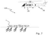
- the rescue operation system 100 comprises a rescue operation device 1 as described previously and a deployment unit 50.
- the deployment unit 50 is an aerial vehicle such as a helicopter 60.
- the deployment unit 50 may be a marine vehicle, a land vehicle or an aerial vehicle, or any combination thereof.
- the marine vehicle may be a marine vessel such as a ship, a boat, an unmanned surface vehicle or an autonomous boat.
- the aerial vehicle may be an aircraft, a helicopter 60, an airplane or an unmanned aerial vehicle such as a drone.
- the deployment unit may be an amphibious vehicle.
- Fig. 8 show a rescue operation device 1 to be deployed during flooding and other rescue operations according to an example.
- the rescue operation device 1 comprises a first inflatable tube layer 2 having at least three linear first side parts 4, each first side parts 4 being connected with a first corner part 5 so that the first inflatable tube layer 2 having at least three first corner parts 5, each first corner part 5 having the same first angle between two adjacent first side parts, a second inflatable tube layer 3 being substantially identical to the first inflatable tube layer 2, and having at least three linear second side parts 6, each second side parts 6 being connected with a second corner part 7 so that the second inflatable tube layer 3 having at least three second corner parts 7, each second corner part 7 having the same second angle between two adjacent second side parts.
- the first inflatable tube layer 2 is arranged above the second inflatable tube layer 3 and is rotated in relation to the second inflatable tube layer 3 so that each first corner parts 5 are projecting radially outwards from each of the second side parts 6 with a first projection distance D 1 and each second corner parts are projecting radially outwards from each of the first side parts 4 with a second projection distance D 2 , the first projection distance D 1 being substantially equal to the second projection distance D 2 , and the first inflatable tube layer 2 and the second inflatable tube layer 3 being connected via a floor part 10, the floor part has a first floor face and a second floor face.
- Relative terms such as “below” or “above” or “upper” or “lower” or “horizontal” or “vertical” may be used herein to describe a relationship of one element to another element as illustrated in the Figures. It will be understood that these terms and those discussed above are intended to encompass different orientations of the system and/or device in addition to the orientation depicted in the Figures. It will be understood that when an element is referred to as being “connected” or “coupled” to another element, it can be directly connected or coupled to the other element, or intervening elements may be present. In contrast, when an element is referred to as being “directly connected” or “directly coupled” to another element, there are no intervening elements present.
Landscapes
- Engineering & Computer Science (AREA)
- Mechanical Engineering (AREA)
- Ocean & Marine Engineering (AREA)
- Emergency Lowering Means (AREA)
Priority Applications (2)
| Application Number | Priority Date | Filing Date | Title |
|---|---|---|---|
| EP23202095.8A EP4534405A1 (fr) | 2023-10-06 | 2023-10-06 | Dispositif d'opération de secours |
| PCT/EP2024/077947 WO2025073898A1 (fr) | 2023-10-06 | 2024-10-04 | Dispositif d'opération de sauvetage |
Applications Claiming Priority (1)
| Application Number | Priority Date | Filing Date | Title |
|---|---|---|---|
| EP23202095.8A EP4534405A1 (fr) | 2023-10-06 | 2023-10-06 | Dispositif d'opération de secours |
Publications (1)
| Publication Number | Publication Date |
|---|---|
| EP4534405A1 true EP4534405A1 (fr) | 2025-04-09 |
Family
ID=88295962
Family Applications (1)
| Application Number | Title | Priority Date | Filing Date |
|---|---|---|---|
| EP23202095.8A Withdrawn EP4534405A1 (fr) | 2023-10-06 | 2023-10-06 | Dispositif d'opération de secours |
Country Status (2)
| Country | Link |
|---|---|
| EP (1) | EP4534405A1 (fr) |
| WO (1) | WO2025073898A1 (fr) |
Citations (4)
| Publication number | Priority date | Publication date | Assignee | Title |
|---|---|---|---|---|
| BE441210A (fr) * | 1941-04-18 | 1941-05-31 | Engin maritime de sauvetage | |
| EP0140501A1 (fr) * | 1983-09-07 | 1985-05-08 | The Garrett Corporation | Plate-forme flottante |
| US4614500A (en) * | 1983-09-07 | 1986-09-30 | The Garrett Corporation | Flotation platform |
| US5800225A (en) * | 1995-09-28 | 1998-09-01 | Shoaff, Iii; Frederick B. | Aviation auto-inflatable life raft |
-
2023
- 2023-10-06 EP EP23202095.8A patent/EP4534405A1/fr not_active Withdrawn
-
2024
- 2024-10-04 WO PCT/EP2024/077947 patent/WO2025073898A1/fr active Pending
Patent Citations (4)
| Publication number | Priority date | Publication date | Assignee | Title |
|---|---|---|---|---|
| BE441210A (fr) * | 1941-04-18 | 1941-05-31 | Engin maritime de sauvetage | |
| EP0140501A1 (fr) * | 1983-09-07 | 1985-05-08 | The Garrett Corporation | Plate-forme flottante |
| US4614500A (en) * | 1983-09-07 | 1986-09-30 | The Garrett Corporation | Flotation platform |
| US5800225A (en) * | 1995-09-28 | 1998-09-01 | Shoaff, Iii; Frederick B. | Aviation auto-inflatable life raft |
Also Published As
| Publication number | Publication date |
|---|---|
| WO2025073898A1 (fr) | 2025-04-10 |
Similar Documents
| Publication | Publication Date | Title |
|---|---|---|
| US3883913A (en) | Aquastabilized survival raft | |
| US8512089B2 (en) | Floatable unit for evacuation purposes | |
| US3610194A (en) | Submerged offshore fluid storage facility | |
| US20190112014A1 (en) | Ship having anti-sinking and anti-capsize device for emergency | |
| AU663466B2 (en) | Self-righting inflatable life raft | |
| CN107926802B (zh) | 一种沉浮式深海气囊养殖网箱 | |
| EP2720937B1 (fr) | Unité flottante gonflable | |
| US3428978A (en) | Shark screen | |
| US11078640B2 (en) | Oil spill spread prevention by immediate containment | |
| WO2014125503A2 (fr) | Canot de sauvetage arrondi | |
| US9573666B2 (en) | Longitudinal scoops for rolling stability | |
| US9259368B2 (en) | Patient transporter with sponsons | |
| US5662506A (en) | Raft with water displacing floor and method therefor | |
| EP4534405A1 (fr) | Dispositif d'opération de secours | |
| EP2714502B1 (fr) | Unité gonflable pour équipement de sauvetage | |
| US3706206A (en) | Lightweight readily portable underwater habitation and method of assembly and emplacement | |
| US20150151817A1 (en) | Inflatable liferaft with easy access configuration | |
| US20070238373A1 (en) | Buoyant visibility device | |
| WO2005104832A1 (fr) | Cages d'aquaculture de haute mer auto-deployables et structures sous-marines | |
| SE507965C2 (sv) | Räddningsflotte | |
| CN121969550A (zh) | 救援作业装置 | |
| KR20160130935A (ko) | 해양선박구조장치와구명장비 | |
| ES2810748T3 (es) | Sistema y método de barrera de contención re-inflable a bordo | |
| KR102660095B1 (ko) | 압력용기 일체형 리프팅 백 | |
| CN103342158A (zh) | 四面体救生舱 |
Legal Events
| Date | Code | Title | Description |
|---|---|---|---|
| PUAI | Public reference made under article 153(3) epc to a published international application that has entered the european phase |
Free format text: ORIGINAL CODE: 0009012 |
|
| STAA | Information on the status of an ep patent application or granted ep patent |
Free format text: STATUS: THE APPLICATION HAS BEEN PUBLISHED |
|
| AK | Designated contracting states |
Kind code of ref document: A1 Designated state(s): AL AT BE BG CH CY CZ DE DK EE ES FI FR GB GR HR HU IE IS IT LI LT LU LV MC ME MK MT NL NO PL PT RO RS SE SI SK SM TR |
|
| STAA | Information on the status of an ep patent application or granted ep patent |
Free format text: STATUS: THE APPLICATION IS DEEMED TO BE WITHDRAWN |
|
| 18D | Application deemed to be withdrawn |
Effective date: 20251010 |