EP4535757A1 - Übertragungsverfahren und -vorrichtung sowie endgerät - Google Patents
Übertragungsverfahren und -vorrichtung sowie endgerät Download PDFInfo
- Publication number
- EP4535757A1 EP4535757A1 EP22949723.5A EP22949723A EP4535757A1 EP 4535757 A1 EP4535757 A1 EP 4535757A1 EP 22949723 A EP22949723 A EP 22949723A EP 4535757 A1 EP4535757 A1 EP 4535757A1
- Authority
- EP
- European Patent Office
- Prior art keywords
- information
- application
- request
- indication information
- technology stack
- Prior art date
- Legal status (The legal status is an assumption and is not a legal conclusion. Google has not performed a legal analysis and makes no representation as to the accuracy of the status listed.)
- Pending
Links
Images





Classifications
-
- H—ELECTRICITY
- H04—ELECTRIC COMMUNICATION TECHNIQUE
- H04L—TRANSMISSION OF DIGITAL INFORMATION, e.g. TELEGRAPHIC COMMUNICATION
- H04L65/00—Network arrangements, protocols or services for supporting real-time applications in data packet communication
- H04L65/60—Network streaming of media packets
- H04L65/75—Media network packet handling
-
- H—ELECTRICITY
- H04—ELECTRIC COMMUNICATION TECHNIQUE
- H04L—TRANSMISSION OF DIGITAL INFORMATION, e.g. TELEGRAPHIC COMMUNICATION
- H04L67/00—Network arrangements or protocols for supporting network services or applications
- H04L67/14—Session management
- H04L67/141—Setup of application sessions
-
- H—ELECTRICITY
- H04—ELECTRIC COMMUNICATION TECHNIQUE
- H04L—TRANSMISSION OF DIGITAL INFORMATION, e.g. TELEGRAPHIC COMMUNICATION
- H04L67/00—Network arrangements or protocols for supporting network services or applications
- H04L67/14—Session management
- H04L67/146—Markers for unambiguous identification of a particular session, e.g. session cookie or URL-encoding
-
- H—ELECTRICITY
- H04—ELECTRIC COMMUNICATION TECHNIQUE
- H04L—TRANSMISSION OF DIGITAL INFORMATION, e.g. TELEGRAPHIC COMMUNICATION
- H04L69/00—Network arrangements, protocols or services independent of the application payload and not provided for in the other groups of this subclass
- H04L69/18—Multiprotocol handlers, e.g. single devices capable of handling multiple protocols
-
- H—ELECTRICITY
- H04—ELECTRIC COMMUNICATION TECHNIQUE
- H04L—TRANSMISSION OF DIGITAL INFORMATION, e.g. TELEGRAPHIC COMMUNICATION
- H04L69/00—Network arrangements, protocols or services independent of the application payload and not provided for in the other groups of this subclass
- H04L69/24—Negotiation of communication capabilities
-
- H—ELECTRICITY
- H04—ELECTRIC COMMUNICATION TECHNIQUE
- H04N—PICTORIAL COMMUNICATION, e.g. TELEVISION
- H04N21/00—Selective content distribution, e.g. interactive television or video on demand [VOD]
- H04N21/40—Client devices specifically adapted for the reception of or interaction with content, e.g. set-top-box [STB]; Operations thereof
- H04N21/43—Processing of content or additional data, e.g. demultiplexing additional data from a digital video stream; Elementary client operations, e.g. monitoring of home network or synchronising decoder's clock; Client middleware
- H04N21/436—Interfacing a local distribution network, e.g. communicating with another STB or one or more peripheral devices inside the home
- H04N21/43615—Interfacing a Home Network, e.g. for connecting the client to a plurality of peripherals
-
- H—ELECTRICITY
- H04—ELECTRIC COMMUNICATION TECHNIQUE
- H04N—PICTORIAL COMMUNICATION, e.g. TELEVISION
- H04N21/00—Selective content distribution, e.g. interactive television or video on demand [VOD]
- H04N21/40—Client devices specifically adapted for the reception of or interaction with content, e.g. set-top-box [STB]; Operations thereof
- H04N21/43—Processing of content or additional data, e.g. demultiplexing additional data from a digital video stream; Elementary client operations, e.g. monitoring of home network or synchronising decoder's clock; Client middleware
- H04N21/436—Interfacing a local distribution network, e.g. communicating with another STB or one or more peripheral devices inside the home
- H04N21/4363—Adapting the video stream to a specific local network, e.g. a Bluetooth® network
- H04N21/43637—Adapting the video stream to a specific local network, e.g. a Bluetooth® network involving a wireless protocol, e.g. Bluetooth®, RF or wireless LAN [IEEE 802.11]
-
- H—ELECTRICITY
- H04—ELECTRIC COMMUNICATION TECHNIQUE
- H04N—PICTORIAL COMMUNICATION, e.g. TELEVISION
- H04N21/00—Selective content distribution, e.g. interactive television or video on demand [VOD]
- H04N21/60—Network structure or processes for video distribution between server and client or between remote clients; Control signalling between clients, server and network components; Transmission of management data between server and client, e.g. sending from server to client commands for recording incoming content stream; Communication details between server and client
- H04N21/63—Control signaling related to video distribution between client, server and network components; Network processes for video distribution between server and clients or between remote clients, e.g. transmitting basic layer and enhancement layers over different transmission paths, setting up a peer-to-peer communication via Internet between remote STB's; Communication protocols; Addressing
- H04N21/643—Communication protocols
-
- H—ELECTRICITY
- H04—ELECTRIC COMMUNICATION TECHNIQUE
- H04W—WIRELESS COMMUNICATION NETWORKS
- H04W4/00—Services specially adapted for wireless communication networks; Facilities therefor
- H04W4/06—Selective distribution of broadcast services, e.g. multimedia broadcast multicast service [MBMS]; Services to user groups; One-way selective calling services
-
- H—ELECTRICITY
- H04—ELECTRIC COMMUNICATION TECHNIQUE
- H04N—PICTORIAL COMMUNICATION, e.g. TELEVISION
- H04N21/00—Selective content distribution, e.g. interactive television or video on demand [VOD]
- H04N21/40—Client devices specifically adapted for the reception of or interaction with content, e.g. set-top-box [STB]; Operations thereof
- H04N21/41—Structure of client; Structure of client peripherals
- H04N21/414—Specialised client platforms, e.g. receiver in car or embedded in a mobile appliance
- H04N21/41422—Specialised client platforms, e.g. receiver in car or embedded in a mobile appliance located in transportation means, e.g. personal vehicle
Definitions
- wireless projection technologies mainly include a Wi-Fi Miracast screen mirroring and projection technology and a digital living network alliance (digital living network alliance, DLNA) projection technology.
- the Wi-Fi Miracast screen mirroring and projection technology and the DLNA projection technology support transmission only based on an internet protocol (internet protocol, IP) technology stack, but do not support transmission based on other types of technology stacks. Consequently, for some devices that do not support the IP technology stack, signaling or data transmission cannot be implemented between a source (source) device and a sink (sink) device.
- IP internet protocol
- sink sink
- Embodiments of this application provide a transmission method and apparatus, and a terminal.
- a source device or a sink device may flexibly establish transmission channels based on different technology stack types, to implement signaling and data transmission.
- a transmission method includes: receiving first indication information, where the first indication information indicates a first technology stack type corresponding to a first application; establishing, based on the first indication information, a transmission channel that is based on the first technology stack type; and sending signaling and/or data of the first application through the transmission channel, or receiving signaling and/or data of the first application through the transmission channel.
- the first technology stack type is a technology stack type that is of the first application and that is supported by the device that sends the first indication information.
- the device that receives the first indication information may be a source device.
- the technical solution in embodiments of this application may be applied to a SparkLink wireless projection technology.
- the sink device may include the first indication information in the SLB system message or the SLE broadcast message.
- the source device that receives the SLB system message or the SLE broadcast message may determine the first technology stack type corresponding to the first application in the sink device.
- the source device may establish the transmission channel based on the first technology stack type, to send, to the sink device through the transmission channel, the signaling and/or the data corresponding to the first application.
- the sink device may include the first indication information in the first response information.
- the source device that receives the first response information may determine the first technology stack type corresponding to the first application in the sink device.
- the source device may establish the transmission channel based on the first technology stack type, to send, to the sink device through the transmission channel, the signaling and/or the data corresponding to the first application.
- the first request information is carried in an access request frame
- the first response information is carried in an access response frame
- the technical solution in embodiments of this application may be applied to the SparkLink wireless projection technology.
- the sink device may include the first indication information in the access response frame.
- the source device that receives the access response frame may determine the first technology stack type corresponding to the first application in the sink device.
- the source device may establish the transmission channel based on the first technology stack type, to send, to the sink device through the transmission channel, the signaling and/or the data corresponding to the first application.
- the source device may include the second indication information in the second request information.
- the sink device may learn of the second technology stack type corresponding to the first application in the source device. In this way, when the first technology stack type matches the second technology stack type, the sink device may establish the transmission channel based on the first technology stack type.
- the device that receives the first indication information may be the sink device.
- the method before the receiving the first indication information sent by a second device, the method further includes: sending broadcast information, where the broadcast information includes second indication information, and the second indication information indicates a second technology stack type corresponding to the first application.
- the technical solution in embodiments of this application may be applied to a SparkLink wireless projection technology.
- the sink device may include the second indication information in the SLB system message or the SLE broadcast message.
- the source device that receives the SLB system message or the SLE broadcast message may determine the second technology stack type corresponding to the first application in the sink device.
- the source device may establish the transmission channel based on the second technology stack type, to send, to the sink device through the transmission channel, the signaling and/or the data corresponding to the first application.
- the first request information is carried in an access request frame
- the first response information is carried in an access response frame
- the technical solution in embodiments of this application may be applied to the SparkLink wireless projection technology.
- the sink device may include the second indication information in the access response frame.
- the source device that receives the access response frame may determine the second technology stack type corresponding to the first application in the sink device.
- the source device may establish the transmission channel based on the second technology stack type, to send, to the sink device through the transmission channel, the signaling and/or the data corresponding to the first application.
- the receiving the first indication information sent by a second device includes: receiving a video application transmission request message sent by the second device, where the video application transmission request message includes the first indication information.
- the receiving the first indication information sent by a second device includes: receiving second request information sent by the second device, where the second request information is used to request to perform capability negotiation with the first device, and the second request information includes the first indication information.
- the method further includes: sending second response information for the second request information to the second device, where the second response information includes second indication information, and the second indication information indicates a second technology stack type corresponding to the first application.
- the first technology stack type includes an IP technology stack or a non-IP technology stack.
- a transmission apparatus includes: a transceiver unit, configured to receive first indication information, where the first indication information indicates a first technology stack type corresponding to a first application; a channel establishment unit, configured to establish, based on the first indication information, a transmission channel that is based on the first technology stack type; and the transceiver unit is further configured to: send signaling and/or data of the first application through the transmission channel, or receive signaling and/or data of the first application through the transmission channel.
- the transceiver unit is further configured to: before receiving the first indication information from the first device, send first request information to the first device, where the first request information is used to request to access the first device; and the transceiver unit is specifically configured to: receive first response information for the first request information from the first device, where the first response information includes the first indication information.
- the first request information is carried in an access request frame
- the first response information is carried in an access response frame
- the second request information includes second indication information, and the second indication information indicates a second technology stack type corresponding to the first application.
- the transceiver unit is further configured to: before receiving the first indication information sent by the second device, receive first request information sent by the second device, where the first request information is used to request to access a first device; and send first response information for the first request information to the second device, where the first response information includes second indication information, and the second indication information indicates a second technology stack type corresponding to the first application.
- the second request information is carried in a video projection application capability negotiation request message
- the second response information is carried in a video projection application capability negotiation response message.
- a transmission apparatus includes a first protocol layer processing unit, a third protocol layer processing unit, and a fourth protocol layer processing unit.
- the first protocol layer processing unit is configured to send a device information disclosure request message to the third protocol layer processing unit.
- the device information disclosure request message includes identification information of a first application and identification information of a first technology stack type.
- the third protocol layer processing unit is configured to receive the device information disclosure request message sent by the first protocol layer processing unit, and send first indication information to the fourth protocol layer processing unit.
- the first indication information indicates a first technology stack type corresponding to the first application.
- the fourth protocol layer processing unit is configured to: receive the first indication information sent by the third protocol layer processing unit, and send the first indication information.
- the third protocol layer processing unit is specifically configured to send a system message to the fourth protocol layer processing unit, where the system message includes the first indication information.
- the fourth protocol layer processing unit is configured to send the system message.
- the first protocol layer processing unit is further configured to: receive the identification information of the first application and the identification information of the first technology stack type that are sent by the third protocol layer processing unit, send the identification information of the first application and the identification information of the first technology stack type to the second protocol layer processing unit, and send a first instruction to the third protocol layer processing unit.
- the first instruction indicates the third protocol layer processing unit to establish a transmission channel based on the first technology stack type.
- the second protocol layer processing unit is configured to: receive the identification information of the first application and the identification information of the first technology stack type that are sent by the first protocol layer processing unit, and select, based on the identification information of the first technology stack type, a first control and management module to perform capability negotiation.
- the third protocol layer processing unit is further configured to establish, based on the first instruction, a transmission channel that is based on the first technology stack type.
- the first technology stack type includes an IP technology stack or a non-IP technology stack.
- the second protocol layer processing unit is specifically configured to select, based on the identification information of the first technology stack type, the first control and management module to negotiate a video encoding and decoding capability.
- the first protocol layer processing unit may correspond to a SparkLink basic application layer
- the third protocol layer processing unit may correspond to a SparkLink basic service layer
- the fourth protocol layer processing unit may correspond to a SparkLink access layer.
- a transmission apparatus includes a first protocol layer processing unit, a second protocol layer processing unit, a third protocol layer processing unit, and a fourth protocol layer processing unit.
- the first protocol layer processing unit is configured to send data and identification information of a first technology stack type to the second protocol layer processing unit.
- the second protocol layer processing unit is configured to receive the data and the identification information of the first technology stack type that are sent by the first protocol layer processing unit.
- the second protocol layer processing unit is further configured to select, based on the identification information of the first technology stack type, a first data encapsulation module to encapsulate the data, to obtain encapsulated data.
- the second protocol layer processing unit is further configured to send the encapsulated data to the third protocol layer processing unit.
- the second protocol layer processing unit includes the first data encapsulation module and a second data encapsulation module.
- the first data encapsulation module has a correspondence with the first technology stack type
- the second data encapsulation module has a correspondence with a second technology stack type.
- a transmission apparatus includes a first protocol layer processing unit, a second protocol layer processing unit, a third protocol layer processing unit, and a fourth protocol layer processing unit.
- the fourth protocol layer processing unit is configured to receive processed data sent by a peer device, and send the processed data to the third protocol layer processing unit.
- the third protocol layer processing unit is configured to receive the processed data sent by the fourth protocol layer processing unit, and obtain encapsulated data based on the processed data.
- the third protocol layer processing unit is further configured to send the encapsulated data to the second protocol layer processing unit.
- the second protocol layer processing unit is further configured to decapsulate the encapsulated data to obtain decapsulated data.
- the second protocol layer processing unit is further configured to send the decapsulated data to the first protocol layer processing unit.
- the first protocol layer processing unit is further configured to receive the decapsulated data sent by the second protocol layer processing unit.
- the first protocol layer processing unit, the second protocol layer processing unit, the third protocol layer processing unit, and the fourth protocol layer processing unit may be physical units, or may be virtual units.
- the first indication information includes the identification information of the first application and identification information of the first technology stack type.
- the third protocol layer processing unit sends first indication information to the fourth protocol layer processing unit includes: The third protocol layer processing unit sends a scanning request message to the fourth protocol layer processing unit, where the scanning request message includes the first indication information.
- the third protocol layer processing unit sends the first indication information to the fourth protocol layer processing unit includes: The third protocol layer processing unit sends a broadcast message to the fourth protocol layer processing unit, where the broadcast message includes the first indication information; and the fourth protocol layer processing unit sends the broadcast message.
- a transmission method is provided, where the transmission method is applied to a transmission apparatus including a first protocol layer processing unit, a second protocol layer processing unit, a third protocol layer processing unit, and a fourth protocol layer processing unit, and the transmission method includes:
- the fourth protocol layer processing unit receives first indication information and sends the first indication information to the third protocol layer processing unit, where the first indication information indicates a first technology stack type corresponding to a first application;
- the third protocol layer processing unit receives the first indication information sent by the fourth protocol layer processing unit, and parses the first indication information to obtain identification information of the first application and identification information of the first technology stack type;
- the third protocol layer processing unit sends the identification information of the first application and the identification information of the first technology stack type to the first protocol layer processing unit;
- the first protocol layer processing unit receives the identification information of the first application and the identification information of the first technology stack type that are sent by the third protocol layer processing unit;
- the first protocol layer processing unit sends the identification information of the first application and the identification information of the first technology stack type
- the third protocol layer processing unit processes the encapsulated data includes: The third protocol layer processing unit fragments or aggregates the encapsulated data, selects a data transmission mode, and selects an interface for transmitting data.
- a transmission method is provided, where the transmission method is applied to a transmission apparatus including a first protocol layer processing unit, a second protocol layer processing unit, a third protocol layer processing unit, and a fourth protocol layer processing unit, and the transmission method includes: The fourth protocol layer processing unit receives processed data sent by a peer device, and sends the processed data to the third protocol layer processing unit; the third protocol layer processing unit receives the processed data sent by the fourth protocol layer processing unit, and obtains encapsulated data based on the processed data; the third protocol layer processing unit sends the encapsulated data to the second protocol layer processing unit; the second protocol layer processing unit decapsulates the encapsulated data to obtain decapsulated data; the second protocol layer processing unit sends the decapsulated data to the first protocol layer processing unit; and the first protocol layer processing unit receives the decapsulated data sent by the second protocol layer processing unit.
- the SparkLink application layer may send video data (or audio data) to the second protocol layer processing unit, so that the data encapsulation module based on the non-IP technology stack in the second protocol layer processing unit may encapsulate the video data.
- the second protocol layer processing unit may send the encapsulated data to the SparkLink basic service layer.
- a data transmission mode selection module at the SparkLink basic service layer may select a data transmission mode.
- a data fragmentation and aggregation module may fragment or aggregate the encapsulated data.
- a converge and transmission module may select an air interface for data transmission. For example, for data with high transmission reliability, the converge and transmission module may control the SLE air interface and the SLB air interface to perform redundant transmission. For another example, for data in a low power consumption scenario, the converge and transmission module may control the SLE air interface to transmit the data.
- an apparatus includes: a memory, configured to store computer instructions; and a processor, configured to execute the computer instructions stored in the memory, so that the apparatus performs the method in the first aspect, the seventh aspect, the eighth aspect, the ninth aspect, or the tenth aspect.
- a terminal includes the apparatus according to any one of the second aspect, the third aspect, the fourth aspect, the fifth aspect, the sixth aspect, or the eleventh aspect.
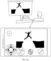
- the mobile phone may project an image of the game application onto a smart screen.
- the user may use the mobile phone as a remote controller.
- the mobile phone may be used as a source device, and the smart screen may be used as a sink device.
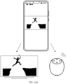
- the mobile phone displays a video playback interface.
- the mobile phone may send a video stream corresponding to a video to the smart screen for display, and the mobile phone may also send an audio stream corresponding to the video to a sound box for audio playback.
- the mobile phone may be used as a source device, and the smart screen and the speaker may be used as sink devices.
- the mobile phone may send a playback link corresponding to the video to the smart screen, so that the smart screen can display an image.
- the mobile phone may send the playback link corresponding to the video to the sound box, so that the sound box can play audio.
- the mobile phone may be used as the source device, and the smart screen and the speaker may be used as the sink devices.
- a Wi-Fi Miracast screen mirroring and projection technology and a DLNA projection technology support only transmission based on an internet protocol (internet protocol, IP) technology stack, and do not support transmission based on another type of technology stack. In this way, for some devices that do not support the IP technology stack, signaling or data cannot be transmitted between the source device and the sink device.
- IP internet protocol
- Embodiments of this application provide a transmission method and apparatus, and a terminal, which may be applied to the scenarios in FIG. 1(a) to FIG. 1(e)
- a video configuration and transmission management sublayer that supports an IP technology stack and a non-IP technology stack is added to the source device or the sink device. Therefore, a transmission channel based on a technology stack can be established between the source device and the sink device, through which signaling and/or data applicable to an application is transmitted. This implements flexible and efficient transmission.
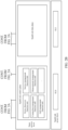
- a video configuration and transmission management sublayer is defined between the SparkLink basic application layer and the SparkLink basic service layer.
- Functional modules at the video configuration and transmission management sublayer include a control and management module and a data encapsulation module.
- the control and management module may complete inter-device capability negotiation, application session management, and the like.
- the control and management module can be further divided into a SparkLink native control and management module and a reuse control and management module.
- the session management module is configured to establish, release, and terminate a session.
- the human-computer interaction module is configured to transmit user input to a video application source device or a video application sink device.
- the user input is a device operation such as a mouse operation, a keyboard operation, or a controller operation, or the user input is a touchscreen operation.
- the device integration module is configured to manage a group including a plurality of associated devices (for example, devices in a same state), to facilitate unified synchronization and service configuration.
- the volume control module is configured to reversely control video and audio playback volume from the video source device or the video sink device.
- the reuse control and management module may include one or more of the following: a real-time streaming protocol (real time streaming protocol, RTSP) module, a user input back channel (user input back channel, UIBC) protocol module, a remote I2C read/write (remote I2C read/write) protocol module, and a multicast domain name system (multicast domain name system, mDNS) protocol module.
- a real-time streaming protocol real time streaming protocol, RTSP
- UIBC user input back channel
- remote I2C read/write remote I2C read/write
- mDNS multicast domain name system
- the SparkLink basic service layer includes a SparkLink control plane and a SparkLink data plane.
- the SparkLink control plane may include one or more of the following: a device discovery function unit, a service management function unit, a connection management function unit, a measurement management function unit, and a QoS management function unit.
- the service management function unit is a logical function entity, and is used for service management and maintenance inside a device and service discovery between devices.
- the connection management function unit supports functions such as establishment, update, and deletion of a transmission channel, maintenance of a mapping relationship between a service port and a transport channel identifier (transport channel identifier, TCID), and maintenance of a mapping relationship between a transmission channel and a SparkLink access layer logical channel.
- functions such as establishment, update, and deletion of a transmission channel, maintenance of a mapping relationship between a service port and a transport channel identifier (transport channel identifier, TCID), and maintenance of a mapping relationship between a transmission channel and a SparkLink access layer logical channel.
- the measurement management function unit supports triggering the SparkLink access layer to measure quality of a physical layer signal, measuring performance of an existing transmission channel in the light, and provides a unified measurement service interface for other function units (such as the QoS management function unit and a 5th generation mobile communication technology (5th generation mobile communication technology, 5G) convergence function unit) or an authorized application inside the SparkLink device.
- a corresponding function unit is allowed to provide configuration information about expected measurement to the measurement management function unit and query a measurement result.
- the QoS management function unit is a logical function entity.
- the QoS management function unit can determine a service quality that needs to be provided by a SparkLink wireless communication system based on factors such as service transmission requirements and network conditions, to ensure that a transmission capability of the SparkLink wireless communication system matches the service requirements.
- the SparkLink access layer includes an SLB air interface and an SLE air interface.
- a plurality of video applications have a unique application indication identifier (for example, an application identifier (application identifier, AID) or a universally unique identifier (universally unique identifier, UUID)) and a dynamically allocated port number (port) that are included in the data frame in the SparkLink system in a static allocation or dynamic registration manner, to identify corresponding application data.
- a unique application indication identifier for example, an application identifier (application identifier, AID) or a universally unique identifier (universally unique identifier, UUID)
- port dynamically allocated port number
- FIG. 3A and FIG. 3B are a diagram of signaling and data transmission paths according to an embodiment of this application.
- Capability negotiation between a source device and a sink device can be implemented through an SLB streaming media general management channel based on the non-IP technology stack or an SLB streaming media general management channel based on the IP technology stack.
- a video application session may be established through an SLB streaming media general management channel based on the non-IP technology stack or an SLB streaming media general management channel based on the IP technology stack.
- video stream encapsulation and transmission can be implemented through an SLB streaming media general management channel based on the non-IP technology stack or an SLB streaming media general management channel based on the IP technology stack.
- the SparkLink basic service layer can serve a non-IP video application and an IP video application.
- the native control and management module can request, respond to, subscribe to, or publish monitoring a result through the SLB streaming media general management channel based on the non-IP technology stack.
- the reuse control and management module may request, respond to, subscribe to, or publish a monitoring result through the SLB streaming media general management channel based on the IP technology stack.
- video application session keep-alive or release can be implemented through the SLB streaming media general management channel based on the non-IP technology stack or an SLB streaming media general management channel based on the IP technology stack.
- the following describes a transmission method provided in an embodiment of this application with reference to FIG. 4 to FIG. 13 .
- the transmission method may be used to implement the foregoing device and service discovery phase and the phase of establishing the SLB streaming media general management transmission channel and the multimedia data transmission channel.
- the following uses the source device and the sink device as an example for description.
- this application is not limited to being applied only to the "source device” and the "sink device.” It may be understood that the solutions of this application may be applied to any two nodes that perform communication transmission, for example, a first device and a second device, or a grant node (G node) and a terminal node (T node).
- G node grant node
- T node terminal node
- FIG. 4 is a schematic flowchart of a transmission method 400 according to an embodiment of this application.
- the method may be implemented by a source device and a sink device. As shown in FIG. 4 , the method 400 includes the following steps.
- the sink device sends broadcast information, where the broadcast information includes indication information 1, and the indication information 1 indicates a first technology stack type corresponding to a first application.
- the broadcast information is an SLB system message or an SLE broadcast message.
- the broadcast information includes a device identifier of the sink device.
- the indication information 1 may include a first field and a second field.
- the first field is used to carry identification information of the first application
- the second field is used to carry the information about the first technology stack type.
- a value of a bit carried in the second field is 0, it indicates that the technology stack type corresponding to the first application in the sink device is a non-IP technology stack.
- a value of a bit carried in the second field is 1, it indicates that the technology stack type corresponding to the first application in the sink device is an IP technology stack.
- the indication information 1 may include the first field and the second field, and the first field is used to carry the identification information of the first application.
- the second field does not carry any information, it indicates that the technology stack type corresponding to the first application in the sink device is the non-IP technology stack.
- the second field carries specific information, it indicates that the technology stack type corresponding to the first application in the sink device is the IP technology stack.
- indication information 1 may further include identifiers of three or more applications and information about a technology stack type corresponding to each application.
- the second technology stack type corresponding to the first application in the source device matches the first technology stack type carried in the indication information 1 includes:
- the second technology stack type is the same as the first technology stack type; or the second technology stack type and the first technology stack type are technology stacks of a same type.
- the non-IP technology stack may include a non-IP technology stack A and a non-IP technology stack B. If the second technology stack type is the non-IP technology stack A and the first technology stack type is the non-IP technology stack B, it may be considered that the second technology stack type and the first technology stack type are technology stacks of a same type.
- the sink device sends an access response frame to the source device, where the access response frame is used to indicate that the source device is allowed to access the sink device.
- the source device sends a video application transmission request message to the sink device, where the video application transmission request message includes indication information 2, and the indication information 2 indicates a second technology stack type of the first application.
- the sink device receives the video application transmission request message sent by the source device.
- the indication information 2 may include a fifth field and a sixth field.
- the fifth field is used to carry the identification information of the first application
- the sixth field is used to carry information about the second technology stack type.
- a value of a bit carried in the sixth field is 0, it indicates that the technology stack type corresponding to the first application in the source device is the non-IP technology stack.
- a value of a bit carried in the sixth field is 1, it indicates that the technology stack type corresponding to the first application in the source device is the IP technology stack.
- the indication information 2 may include the fifth field and the sixth field.
- the fifth field is used to carry the identification information of the first application.
- the sixth field does not carry any information, it indicates that the technology stack type corresponding to the first application in the source device is the non-IP technology stack.
- the sixth field carries specific information, it indicates that the technology stack type corresponding to the first application in the source device is the IP technology stack.
- the sink device sends a video application transmission response message to the source device.
- the source device receives the video application transmission response message sent by the sink device.
- the video application transmission response message includes a target device layer-2 identifier (TargetLayer2ID), a media access layer identifier, a source port number, a destination port number, a source transmission channel identifier (srcTCID), a destination transmission channel identifier (dstTCID), and the information about the first technology stack type.
- TigetLayer2ID target device layer-2 identifier
- media access layer identifier a media access layer identifier
- source port number a source port number
- a destination port number a source transmission channel identifier
- dstTCID destination transmission channel identifier
- phase of establishing the SLB streaming media general management transmission channel and the multimedia data transmission channel may include S406 and S407.
- the source device and the sink device may exchange non-default transmission channel establishment signaling through the SLB general management transmission channel based on the information about the first technology stack type received by the source device in the device and service discovery phase, to establish the SLB streaming media general management channel, used by a native control and management module to establish a signaling transmission channel based on the non-IP technology stack, or used by a reuse control and management module to establish a signaling transmission channel based on the IP technology stack.
- an SLB multimedia data transmission channel is established to transmit a non-IP data frame based on a native media encapsulation format or an IP data frame based on an MPEG2-TS encapsulation format.
- FIG. 5 is a schematic flowchart of a transmission method 500 according to an embodiment of this application.
- the method may be implemented by a source device and a sink device. As shown in FIG. 5 , the method 500 includes the following steps.
- the source device receives the broadcast information.
- the broadcast information is an SLB system message or an SLE broadcast message.
- the sink device sends an access response frame to the source device, where the access response frame includes indication information 1, and the indication information 1 indicates information about a first technology stack type corresponding to the first application.
- the source device receives the access response frame sent by the sink device.
- the source device and the sink device may establish a default bearer and activate an SLB general management transmission channel.
- the device and service discovery phase may include S501 to S504.
- the source device sends a video application transmission request message to the sink device, where the video application transmission request message includes indication information 2, and the indication information 2 indicates a second technology stack type of the first application.
- the sink device sends a video application transmission response message to the source device.
- the sink device sends broadcast information.
- S602 The source device sends an access request frame to the sink device.
- the sink device receives the access request frame sent by the source device.
- the source device receives the access response frame sent by the sink device.
- the indication information 1 may further include information that indicates a technology stack type corresponding to the second application.
- the indication information 1 may include a third field and a fourth field.
- the third field is used to carry identification information of the second application
- the fourth field is used to carry information about the technology stack type corresponding to the second application.
- a value of a bit carried in the second field is 0, it indicates that the technology stack type corresponding to the second application in the sink device is a non-IP technology stack.
- a value of a bit carried in the second field is 1, it indicates that the technology stack type corresponding to the second application in the sink device is the IP technology stack.
- the device and service discovery phase may include S601 to S604.
- the sink device receives the video application transmission request message sent by the source device.
- S701 The sink device sends broadcast information.
- the source device receives the broadcast information.
- the method further includes: The source device determines, based on a filter condition, to access the sink device.
- the source device receives the access response frame sent by the sink device.
- the source device and the sink device may establish a default bearer and activate an SLB general management transmission channel.
- the device and service discovery phase may include S701 to S704.
- the source device sends a video projection application capability negotiation request message to the sink device, where the video projection application capability negotiation request message includes indication information 2, and the indication information 2 indicates a second technology stack type of the first application.
- the sink device receives the video projection application capability negotiation request message sent by the source device.
- the video projection application capability negotiation request message further includes other capability information of the source device, for example, an audio/video encoding type or an audio/video decoding type of the source device, or a protocol stack type supported by the source device.
- the sink device sends a video projection application capability negotiation response message to the source device, where the video projection application capability negotiation response message includes indication information 1, and the indication information 1 indicates a first technology stack type of the first application.
- the source device receives the video projection application capability negotiation response message sent by the sink device.
- the indication information 1 may include an identifier of the first application and information about the first technology stack type.
- the video projection application capability negotiation response message may include other capability information of the sink device, for example, an audio/video encoding type or an audio/video decoding type of the sink device, or a protocol stack type supported by the sink device.
- the foregoing end-to-end working procedure of a wireless short-range video projection application may further include a video projection application capability negotiation phase.
- the video projection application capability negotiation phase may include S705 and S706.
- the source device sends a video application transmission request message to the sink device.
- the sink device receives the video application transmission request message sent by the source device.
- the video application transmission request message may further include information such as a source port number, a destination port number, and a QoS parameter.
- the sink device sends a video application transmission response message to the source device.
- the video application transmission response message includes TargetLayer2ID, a source port number, a destination port number, a source transmission channel identifier, a destination transmission channel identifier, and the information about the first technology stack type.
- the foregoing phase of establishing the SLB streaming media general management transmission channel and the multimedia data transmission channel may include S707 and S708.
- S801 The sink device sends broadcast information.
- the source device receives the video projection application capability negotiation response message sent by the sink device.
- S903 The sink device sends an access response frame to the source device.
- the sink device receives the video projection application capability negotiation request message sent by the source device.
- the video projection application capability negotiation request message further includes other capability information of the source device, for example, an audio/video encoding type or an audio/video decoding type of the source device, or a protocol stack type supported by the source device.
- video projection application capability negotiation phase may include S905 and S906.
- the sink device receives the video application transmission request message sent by the source device.
- the sink device sends a video application transmission response message to the source device.
- FIG. 10 is a schematic flowchart of a transmission method 1000 according to an embodiment of this application.
- the method may be implemented by a source device and a sink device. As shown in FIG. 10 , the method 1000 includes the following steps.
- S1003 The sink device sends an access response frame to the source device.
- the source device receives the video projection application capability negotiation response message sent by the sink device.
- phase of establishing the SLB streaming media general management transmission channel and the multimedia data transmission channel may include S1007 and S1008.
- the foregoing method 400 to method 1000 are described by using an example in which the sink device sends the broadcast message, so that the source device discovers the sink device by using the broadcast message and then accesses the sink device.
- the source device may send the broadcast message, so that the sink device discovers the source device by using the broadcast message and then accesses the source device.
- FIG. 11 is a schematic flowchart of a transmission method 1100 according to an embodiment of this application.
- the method 1100 includes the following steps.
- S1101 Receive first indication information, where the first indication information indicates a first technology stack type corresponding to a first application.
- the first application is a video application or an audio application.
- the first device may be the sink device
- the second device may be the source device
- the second device receives the first indication information sent by the first device includes: The second device receives the broadcast information sent by the first device, where the broadcast information includes the first indication information, and the second device sends first request information to the first device, where the first request information is used to request to access the device 1.
- the broadcast information includes an SLB system message or an SLE broadcast message.
- the method before the establishing a transmission channel that is based on the first technology stack type, the method further includes: The second device determines that the first technology stack type matches a second protocol stack type corresponding to the first application in a second device.
- the source device may determine whether the second protocol stack type corresponding to the first application in the source device matches the first protocol stack type indicated in the first indication information. If the second protocol stack type corresponding to the first application in the source device matches the first protocol stack type indicated in the first indication information, the source device may send an access request frame to the sink device. If the second protocol stack type corresponding to the first application in the source device does not match the first protocol stack type indicated in the first indication information, the source device does not send the access request frame to the sink device.
- the method further includes: The second device sends first request information to the first device, where the first request information is used to request to access the first device. That the second device receives the first indication information from a first device includes: The second device receives first response information for the first request information from the first device, where the first response information includes the first indication information.
- the first request information is carried in an access request frame
- the first response information is carried in an access response frame
- the first request information may be carried in the access response frame shown in FIG. 5 or FIG. 6
- the first indication information may be the indication information 1 in the access response frame.
- the first indication information may be carried in the video projection application capability negotiation response message shown in FIG. 7 to FIG. 10 , and the first indication information may be the indication information 1 in the video projection application capability negotiation response message.
- the second request information includes second indication information, and the second indication information indicates a second technology stack type corresponding to the first application.
- the video projection application capability negotiation request message shown in FIG. 7 may carry the second indication information, and the second indication information may be the indication information 2 in the video projection application capability negotiation request message.
- the second indication information may be carried in the access response frame shown in FIG. 5 or FIG. 6 , and the second indication information may be the indication information 1 in the access response frame.
- the sink device may send an access response frame to the source device.
- the access response frame may include the second indication information.
- the first request information is carried in an access request frame
- the first response information is carried in an access response frame
- the method further includes: The first device sends second response information for the second request information to the second device, where the second response information includes second indication information, and the second indication information indicates a second technology stack type corresponding to the first application.
- the sink device may receive, through the transmission channel, the signaling and/or the data of the first application that are/is sent by the source device.
- FIG. 12 is a block diagram of a transmission apparatus 1200 according to an embodiment of this application.
- the transmission apparatus 1200 includes a first protocol layer processing unit 1201, a third protocol layer processing unit 1203, and a fourth protocol layer processing unit 1204.
- the first protocol layer processing unit 1201 is configured to send a device information disclosure request message to the third protocol layer processing unit 1203.
- the device information disclosure request message includes identification information of a first application and identification information of a first technology stack type.
- the third protocol layer processing unit 1203 is configured to receive the device information disclosure request message sent by the first protocol layer processing unit 1201, and send first indication information to the fourth protocol layer processing unit 1204.
- the first indication information indicates a first technology stack type corresponding to the first application.
- the fourth protocol layer processing unit 1204 is configured to: receive the first indication information sent by the third protocol layer processing unit 1203, and send the first indication information.
- the first indication information includes the identification information of the first application and identification information of the first technology stack type.
- the third protocol layer processing unit 1203 is specifically configured to send a broadcast message to the fourth protocol layer processing unit 1204, where the broadcast message includes the first indication information.
- the fourth protocol layer processing unit 1204 is configured to send the broadcast message.
- the transmission apparatus 1200 further includes a second protocol stack processing unit 1202.
- the fourth protocol layer processing unit 1204 is configured to receive first indication information and send the first indication information to the third protocol layer processing unit 1203.
- the first indication information indicates a first technology stack type corresponding to a first application.
- the third protocol layer processing unit 1203 is configured to receive the first indication information sent by the fourth protocol layer processing unit 1204, and parse the first indication information to obtain identification information of the first application and identification information of the first technology stack type.
- the third protocol layer processing unit 1203 is further configured to send the identification information of the first application and the identification information of the first technology stack type to the first protocol layer processing unit 1201.
- the first protocol layer processing unit 1201 is further configured to: receive the identification information of the first application and the identification information of the first technology stack type that are sent by the third protocol layer processing unit, send the identification information of the first application and the identification information of the first technology stack type to the second protocol layer processing unit 1202, and send a first instruction to the third protocol layer processing unit 1203.
- the first instruction indicates the third protocol layer processing unit to establish a transmission channel based on the first technology stack type.
- the second protocol layer processing unit 1202 is configured to: receive the identification information of the first application and the identification information of the first technology stack type that are sent by the first protocol layer processing unit 1201, and select, based on the identification information of the first technology stack type, a first control and management module to perform capability negotiation.
- the third protocol layer processing unit 1203 is further configured to establish, based on the first instruction, a transmission channel that is based on the first technology stack type.
- the first protocol layer processing unit 1201 is further configured to: before receiving the identification information of the first application and the identification information of the first technology stack type that are sent by the third protocol layer processing unit 1203, send a device discovery request to the third protocol layer processing unit 1203.
- the device discovery request includes a scanning parameter
- the scanning parameter includes the identification information of the first application and the identification information of the first technology stack type.
- the third protocol layer processing unit 1203 is further configured to receive the device discovery request sent by the first protocol layer processing unit 1201, and send a scanning configuration command to the fourth protocol layer processing unit 1204.
- the scanning configuration command indicates that the scanning parameter of the fourth protocol layer processing unit 1204 includes the identification information of the first application and the identification information of the first technology stack type.
- the fourth protocol layer processing unit 1204 is further configured to receive the scanning configuration command sent by the third protocol layer processing unit 1203.
- the fourth protocol layer processing unit 1204 is further configured to receive the first indication information and report a scanning result based on the scanning configuration command.
- the second protocol layer processing unit 1202 may be integrated into the first protocol layer processing unit.
- the first technology stack type includes an IP technology stack or a non-IP technology stack.
- the second protocol layer processing unit 1202 is further configured to select, based on the identification information of the first technology stack type, the first control and management module to perform session management, where session management includes session establishment, release, or termination.
- the second protocol layer processing unit 1202 is specifically configured to select, based on the identification information of the first technology stack type, the first control and management module to negotiate a video encoding and decoding capability.
- the fourth protocol layer processing unit 1204 is specifically configured to control an SLB air interface and/or an SLE air interface to receive the first indication information.
- the first protocol layer processing unit 1201 is configured to send data and identification information of a first technology stack type to the second protocol layer processing unit 1202.
- the second protocol layer processing unit 1202 is configured to receive the data and the identification information of the first technology stack type that are sent by the first protocol layer processing unit 1201.
- the second protocol layer processing unit 1202 is further configured to select, based on the identification information of the first technology stack type, a first data encapsulation module to encapsulate the data, to obtain encapsulated data.
- the second protocol layer processing unit 1202 is further configured to send the encapsulated data to the third protocol layer processing unit 1203.
- the second protocol layer processing unit 1202 includes the first data encapsulation module and a second data encapsulation module.
- the first data encapsulation module has a correspondence with the first technology stack type
- the second data encapsulation module has a correspondence with a second technology stack type.
- the third protocol layer processing unit 1203 is specifically configured to fragment or aggregate the encapsulated data, select a data transmission mode, and select an interface for transmitting data.
- the fourth protocol layer processing unit 1204 is configured to receive processed data sent by a peer device, and send the processed data to the third protocol layer processing unit 1203.
- the third protocol layer processing unit 1203 is configured to receive the processed data sent by the fourth protocol layer processing unit 1204, and obtain encapsulated data based on the processed data.
- the third protocol layer processing unit 1203 is further configured to send the encapsulated data to the second protocol layer processing unit 1202.
- the second protocol layer processing unit 1202 is further configured to decapsulate the encapsulated data to obtain decapsulated data.
- the second protocol layer processing unit 1202 is further configured to send the decapsulated data to the first protocol layer processing unit 1201.
- the first protocol layer processing unit 1201 is further configured to receive the decapsulated data sent by the second protocol layer processing unit.
- the first protocol layer processing unit may correspond to the SparkLink basic application layer shown in FIG. 2A and FIG. 2B
- the second protocol layer processing unit may correspond to the video configuration and transmission management sublayer shown in FIG. 2A and FIG. 2B
- the third protocol layer processing unit may correspond to the SparkLink basic service layer shown in FIG. 2A and FIG. 2B
- the fourth protocol layer processing unit may correspond to the SparkLink access layer shown in FIG. 2A and FIG. 2B .
- the first protocol layer processing unit, the second protocol layer processing unit, the third protocol layer processing unit, and the fourth protocol layer processing unit may be physical units, or may be virtual units.
- the first request information is carried in an access request frame
- the first response information is carried in an access response frame
- the second request information is carried in a video projection application capability negotiation request message
- the second response information is carried in a video projection application capability negotiation response message.
- the second request information includes identification information of the first application.
- the transceiver unit 1301 is specifically configured to: receive the first indication information sent by a second device; and receive the signaling and/or the data of the first application sent by the second device through the transmission channel.
- the transceiver unit 1301 is further configured to: before receiving the first indication information from the second device, receive first request information from the second device, where the first request information is used to request to access a first device; and send first response information for the first request information to the second device, where the first response information includes second indication information, and the second indication information indicates a second technology stack type corresponding to the first application.
- the transceiver unit 1301 is specifically configured to receive a video application transmission request message sent by the second device, where the video application transmission request message includes the first indication information.
- the second request information is carried in a video projection application capability negotiation request message
- the second response information is carried in a video projection application capability negotiation response message.
- the processor is a circuit having a signal processing capability.
- the processor may be a circuit having a capability of instruction reading and running, for example, a CPU, a microprocessor, a GPU, or a DSP.
- the processor may implement a specific function based on a logical relationship of a hardware circuit.
- the logical relationship of the hardware circuit is fixed or reconfigurable.
- the processor is a hardware circuit implemented by an ASIC or a PLD, for example, an FPGA.
- a process in which the processor loads a configuration document to implement hardware circuit configuration may be understood as a process in which the processor loads instructions to implement functions of some or all of the foregoing units.
- the processor may alternatively be a hardware circuit designed for artificial intelligence, and may be understood as an ASIC, for example, an NPU, a TPU, or a DPU.
- each unit of the foregoing apparatus may be one or more processors (or processing circuits) configured to implement the foregoing method, for example, a CPU, a GPU, an NPU, a TPU, a DPU, a microprocessor, a DSP, an ASIC, or an FPGA, or a combination of at least two of these processor forms.
- processors or processing circuits
- the storage unit may be a memory
- the processing unit may be a processor
- An embodiment of this application further provides a terminal.
- the terminal may include the foregoing apparatus.
- An embodiment of this application further provides a computer-readable medium.
- the computer-readable medium stores program code, and when the computer program code is run on a computer, the computer is enabled to perform the method.
- the memory may include a read-only memory and a random access memory, and provide instructions and data to the processor.
- sequence numbers of the foregoing processes do not mean execution sequences in various embodiments of this application.
- the execution sequences of the processes should be determined according to functions and internal logic of the processes, and should not be construed as any limitation on the implementation processes of embodiments of this application.
- the disclosed system, apparatus, and method may be implemented in other manners.
- the described apparatus embodiment is merely an example.
- division into the units is merely logical function division and may be other division during actual implementation.
- a plurality of units or components may be combined or integrated into another system, or some features may be ignored or not performed.
- the displayed or discussed mutual couplings or direct couplings or communication connections may be implemented by using some interfaces.
- the indirect couplings or communication connections between the apparatuses or units may be implemented in electronic, mechanical, or other forms.
- the units described as separate parts may or may not be physically separate, and parts displayed as units may or may not be physical units, may be located in one position, or may be distributed on a plurality of network units. Some or all of the units may be selected based on actual requirements to achieve the objectives of the solutions of embodiments.
- the functions When the functions are implemented in the form of a software functional unit and sold or used as an independent product, the functions may be stored in a computer-readable storage medium. Based on such an understanding, the technical solutions of this application may be implemented in a form of a software product.
- the software product is stored in a storage medium, and includes several instructions for instructing a computer device (which may be a personal computer, a server, or a network device) to perform all or some of the steps of the methods described in embodiments of this application.
- the foregoing storage medium includes any medium that can store program code, such as a USB flash drive, a removable hard disk, a read-only memory (read-only memory, ROM), a random access memory (random access memory, RAM), a magnetic disk, or an optical disc.
Landscapes
- Engineering & Computer Science (AREA)
- Signal Processing (AREA)
- Computer Networks & Wireless Communication (AREA)
- Multimedia (AREA)
- Computer Security & Cryptography (AREA)
- Mobile Radio Communication Systems (AREA)
- Communication Control (AREA)
Applications Claiming Priority (1)
| Application Number | Priority Date | Filing Date | Title |
|---|---|---|---|
| PCT/CN2022/103758 WO2024007133A1 (zh) | 2022-07-04 | 2022-07-04 | 一种传输方法、装置和终端 |
Publications (2)
| Publication Number | Publication Date |
|---|---|
| EP4535757A4 EP4535757A4 (de) | 2025-04-09 |
| EP4535757A1 true EP4535757A1 (de) | 2025-04-09 |
Family
ID=89454729
Family Applications (1)
| Application Number | Title | Priority Date | Filing Date |
|---|---|---|---|
| EP22949723.5A Pending EP4535757A1 (de) | 2022-07-04 | 2022-07-04 | Übertragungsverfahren und -vorrichtung sowie endgerät |
Country Status (4)
| Country | Link |
|---|---|
| US (1) | US20250133144A1 (de) |
| EP (1) | EP4535757A1 (de) |
| CN (1) | CN119605149A (de) |
| WO (1) | WO2024007133A1 (de) |
Families Citing this family (2)
| Publication number | Priority date | Publication date | Assignee | Title |
|---|---|---|---|---|
| CN115942255B (zh) * | 2021-09-15 | 2024-09-17 | 华为技术有限公司 | 通道配置方法及装置 |
| CN120980724A (zh) * | 2024-05-15 | 2025-11-18 | 华为技术有限公司 | 通信方法及装置 |
Family Cites Families (11)
| Publication number | Priority date | Publication date | Assignee | Title |
|---|---|---|---|---|
| KR101421587B1 (ko) * | 2007-08-23 | 2014-07-22 | 삼성전자주식회사 | 무선 영상 전화 단말간의 선호 영상 규격을 결정하는 방법및 장치 |
| US8385326B2 (en) * | 2008-12-29 | 2013-02-26 | Microsoft Corporation | Handling early media in VoIP communication with multiple endpoints |
| US8452903B2 (en) * | 2009-03-16 | 2013-05-28 | Apple Inc. | Mobile computing device capabilities for accessories |
| US20180007428A1 (en) * | 2016-06-29 | 2018-01-04 | Intel Corporation | Wireless display implementation of applications |
| US10802672B2 (en) * | 2017-05-05 | 2020-10-13 | Servicenow, Inc. | Software application portfolio discovery and management |
| US10979892B2 (en) * | 2019-07-30 | 2021-04-13 | At&T Intellectual Property I, L.P. | Efficient device capabilities enquiry for 5G or other next generations wireless network |
| CN115396521A (zh) * | 2019-08-09 | 2022-11-25 | 华为技术有限公司 | 一种切换通信协议的方法、装置和系统 |
| CN114449570B (zh) * | 2022-01-26 | 2023-12-05 | 深圳Tcl新技术有限公司 | 通信域量测方法、存储介质及无线通信装置 |
| CN114449602B (zh) * | 2022-01-27 | 2024-02-06 | 深圳Tcl新技术有限公司 | 切换方法、存储介质及无线通信装置 |
| CN114422574B (zh) * | 2022-02-10 | 2024-05-03 | Oppo广东移动通信有限公司 | 连接建立方法、装置、电子设备和计算机可读存储介质 |
| US12531808B2 (en) * | 2022-06-29 | 2026-01-20 | Amazon Technologies, Inc. | Transport protocol selection based on connection state |
-
2022
- 2022-07-04 WO PCT/CN2022/103758 patent/WO2024007133A1/zh not_active Ceased
- 2022-07-04 EP EP22949723.5A patent/EP4535757A1/de active Pending
- 2022-07-04 CN CN202280097697.1A patent/CN119605149A/zh active Pending
-
2024
- 2024-12-24 US US19/001,169 patent/US20250133144A1/en active Pending
Also Published As
| Publication number | Publication date |
|---|---|
| CN119605149A (zh) | 2025-03-11 |
| EP4535757A4 (de) | 2025-04-09 |
| WO2024007133A1 (zh) | 2024-01-11 |
| US20250133144A1 (en) | 2025-04-24 |
Similar Documents
| Publication | Publication Date | Title |
|---|---|---|
| US20250133144A1 (en) | Transmission method and apparatus, and terminal | |
| EP4366274A1 (de) | Kommunikationsverfahren und -vorrichtung sowie kommunikationssystem | |
| US10187925B2 (en) | WiFi display compatible network gateway | |
| US20220368781A1 (en) | PCIe-Based Data Transmission Method and Apparatus | |
| US20220368564A1 (en) | PCIe-Based Data Transmission Method and Apparatus | |
| CN102546319B (zh) | 物联网终端互通的方法及系统 | |
| US11995020B2 (en) | PCIe data transmission method and apparatus | |
| CN112698942B (zh) | 一种人工智能服务系统、主控装置和从控装置 | |
| TW201220845A (en) | Wireless clone mode display | |
| EP4080839A1 (de) | Verfahren und vorrichtung zur datenübertragung auf pcie-basis | |
| US12147370B2 (en) | PCIe-based data transmission method, apparatus, and system | |
| EP4084422A1 (de) | Pcie-basiertes datenübertragungsverfahren, -gerät und -system | |
| CN104683312A (zh) | 媒体复用协商的方法和装置 | |
| CN116033396B (zh) | 传输通道的重配置方法、装置和电子设备 | |
| WO2025108149A1 (zh) | 跨设备播放方法和电子设备 | |
| WO2014207899A1 (ja) | 通信装置および通信方法 | |
| WO2024007998A1 (zh) | 一种数据传输的方法、电子设备和通信系统 | |
| CN115297356B (zh) | 设备交互方法、系统及装置 | |
| WO2024160146A1 (zh) | 设备能力协商方法及相关设备 | |
| US20090073982A1 (en) | Tcp packet communication device and techniques related thereto | |
| CN121444416A (zh) | 虚拟通路建立方法及装置 | |
| CN121444530A (zh) | 带宽协商方法及装置 | |
| CN121464617A (zh) | 带宽申请方法及装置 | |
| WO2025111934A1 (zh) | Usb隧道管理方法及装置 | |
| WO2026056258A1 (zh) | 数据渲染方法、媒体处理网元、终端设备及存储介质 |
Legal Events
| Date | Code | Title | Description |
|---|---|---|---|
| STAA | Information on the status of an ep patent application or granted ep patent |
Free format text: STATUS: THE INTERNATIONAL PUBLICATION HAS BEEN MADE |
|
| PUAI | Public reference made under article 153(3) epc to a published international application that has entered the european phase |
Free format text: ORIGINAL CODE: 0009012 |
|
| STAA | Information on the status of an ep patent application or granted ep patent |
Free format text: STATUS: REQUEST FOR EXAMINATION WAS MADE |
|
| 17P | Request for examination filed |
Effective date: 20250102 |
|
| A4 | Supplementary search report drawn up and despatched |
Effective date: 20250210 |
|
| AK | Designated contracting states |
Kind code of ref document: A1 Designated state(s): AL AT BE BG CH CY CZ DE DK EE ES FI FR GB GR HR HU IE IS IT LI LT LU LV MC MK MT NL NO PL PT RO RS SE SI SK SM TR |
|
| DAV | Request for validation of the european patent (deleted) | ||
| DAX | Request for extension of the european patent (deleted) | ||
| STAA | Information on the status of an ep patent application or granted ep patent |
Free format text: STATUS: EXAMINATION IS IN PROGRESS |