EP4538459A1 - Changeur de traverses - Google Patents
Changeur de traverses Download PDFInfo
- Publication number
- EP4538459A1 EP4538459A1 EP23202844.9A EP23202844A EP4538459A1 EP 4538459 A1 EP4538459 A1 EP 4538459A1 EP 23202844 A EP23202844 A EP 23202844A EP 4538459 A1 EP4538459 A1 EP 4538459A1
- Authority
- EP
- European Patent Office
- Prior art keywords
- sleeper
- clamper
- base structure
- link
- actuator
- Prior art date
- Legal status (The legal status is an assumption and is not a legal conclusion. Google has not performed a legal analysis and makes no representation as to the accuracy of the status listed.)
- Withdrawn
Links
Images


Classifications
-
- E—FIXED CONSTRUCTIONS
- E01—CONSTRUCTION OF ROADS, RAILWAYS, OR BRIDGES
- E01B—PERMANENT WAY; PERMANENT-WAY TOOLS; MACHINES FOR MAKING RAILWAYS OF ALL KINDS
- E01B29/00—Laying, rebuilding, or taking-up tracks; Tools or machines therefor
- E01B29/06—Transporting, laying, removing or renewing sleepers
-
- E—FIXED CONSTRUCTIONS
- E01—CONSTRUCTION OF ROADS, RAILWAYS, OR BRIDGES
- E01B—PERMANENT WAY; PERMANENT-WAY TOOLS; MACHINES FOR MAKING RAILWAYS OF ALL KINDS
- E01B29/00—Laying, rebuilding, or taking-up tracks; Tools or machines therefor
- E01B29/05—Transporting, laying, removing, or renewing both rails and sleepers
Definitions
- the proposed technology relates generally to rail and sleeper handling, and in particular to an implement, or excavator attachment for replacing and installing sleepers, or cross-ties, to a train rail, or train track.
- a sleeper, or cross-tie, changer for use with a an excavator arm, for handling a sleeper having a first track tension clamp and a second track tension clamp arranged to cooperate and engage opposite sides of a rail, to secure, or lock, the sleeper to the rail
- the sleeper changer comprising: a base structure, a gripper connected to the base structure, arranged to grip, and secure the sleeper in a mounting position relative to the base structure, a clamper, arranged to cooperate and engage the first track tension clamp and the second track tension clamp, a mechanical linkage connected to the base structure and the clamper, and an actuator operationally coupled to the mechanical linkage, wherein the mechanical linkage and the actuator are arranged to set the clamper in a first position and a second position relative to the base structure, or the gripper, wherein in the second position the clamp is positioned to engage the first track tension clamp and a second track tension clamp, with the sleeper at the mounting position.
- the sleeper, or cross-tie, changer comprises a base structure.
- the base structure, or base has a forward end that defines a forward facing direction and an opposite arranged rear end that defines a rearward facing direction.
- the base structure further comprises an upper end that defines an upper facing direction, and an opposite arranged lower end that defines a downward facing direction.
- the upper direction and the downward direction are arranged transverse to the forward direction and the rearward direction.
- the base structure may comprise a coupler.
- the coupler may be arranged to couple, or connect, the sleeper changer to an excavator, or working vehicle, arm.
- the coupler may be a quick coupler. It is understood that a quick coupler may comprise at least a first and a second element fixed to the sleeper changer, wherein the first and second element are arranged to engage and lock to at least one fixed element and a movable element arranged on a coupler arranged on an excavator arm.
- the quick coupler may be formed by a first and a second parallel and spaced apart axles, or bars, arranged to engage a cooperating first and a second parallel and spaced apart hooks arranged on the excavator arm.
- the hooks may be arranged on the sleeper changer and the first and a second parallel and spaced apart axles may be arranged on the excavator arm.
- the quick coupler may comprise a first and a second axle aligned about an axis, and a parallel and spaced apart bar arranged to engage a pivotable latch or linear bar arranged at the excavator arm coupler.
- the upper end of the base structure may define a geometric plane.
- the base structure may comprise an upper surface, facing in the upper direction, and the upper surface may define the geometric plane.
- the quick coupler may define a the geometric plane.
- the first and second spaced apart axles forming the quick coupler as discussed above may define a geometric plane.
- the geometric plane may thus face in the upward facing direction.
- the coupler may be arranged on, or parallel to, the geometric plane or to the upper surface.
- the coupler may be arranged at an incline relative to the geometric plane of the base structure.
- the incline, or coupler tilt angle, or offset angle, relative to the geometric plane of the base structure may be in the range of 5-10 degrees, such as 7 degrees. This allows for the coupler of the sleeper changer to account for any of axis rotation of a tiltrotor coupled to the sleeper changer.
- the sleeper changer may comprise a working blade used during ballast work.
- the blade may be connected to, and extend outwards from, the base structure, in a forward direction.
- the blade may attach, or be connected, to the forward end or forward surface, of the base structure.
- the blade may have a longitudinal extension and a transverse extension.
- the transverse extension may be aligned with the forward direction of the base structure.
- the longitudinal extension may be transverse, or perpendicular, to the transverse extension.
- the blade may outline a rectangle.
- the blade may be curved in the transverse direction to facilitate digging, or ballast work.
- the blade may comprise cutouts, or openings, arranged to receive the rail in operation.
- the blade may extend at an incline, or at an angle, relative to the geometric plane of the base structure.
- the incline may be in the range of 10 to 30 degrees, such as 20 degrees.
- the blade may taper in a forward direction.
- the gripper is connected to the base structure, and is arranged to grip, and secure the sleeper in a mounting position relative to the base structure.
- the gripper may be connected, or arranged, to the base structure, at an opposite end from the coupler.
- the gripper may extend in the downwards direction, transverse to the forward direction. This enables an operator to have a less unobstructed view of the gripper and sleeper when a sleeper is picked up and held in a mounting position.
- the gripper may comprise a pair of cooperating and spaced apart teeth that form a jaw.
- the teeth may be arranged transverse to, or be spaced apart along or parallel to, the geometric plane of the base structure.
- the teeth may be arranged to open, or widen the opening of, the jaw to receive a sleeper in a direction transverse to the geometric plane.
- the jaw may open and the sleeper changer may be moved in a downwards direction to receive and grip a sleeper.
- the pair of cooperating and spaced apart teeth may be formed by a first tooth fixedly connected to the base structure and a second tooth pivotally connected to the base structure. This means that the second tooth may pivot, around an axis, relative to the base structure and that the first tooth is fixed and may not pivot relative to the base structure. This reduces the risk that the pivoting mechanism or actuator is damaged when only the fixedly connected tooth, or teeth, are used during sleeper removal, such as by pushing or pulling with the tooth, or teeth, on a sleeper.
- the axis may be parallel to the geometric plane or transverse to the downwards direction.
- the pivotally connected second tooth may be operationally coupled to an actuator.
- the actuator may be a linear actuator.
- the linear actuator may be an electromechanical actuator or a hydraulic cylinder, coupled to the base structure and the tooth.
- the pivot axis may be arranged parallel to the geometric plane of the base structure.
- the jaw may be formed by two pairs of cooperating and spaced apart teeth, such as two fixedly connected teeth and two pivotally arranged teeth.
- the jaw may further comprise contact elements, that engage and contact a sleeper when a sleeper is gripped by the gripper.
- the contact elements may be arranged to the first and second tooth or to the first pair of teeth and the second pair of teeth.
- the contact elements may be of an elastomer.
- the elastomer may be a synthetic rubber.
- the synthetic rubber may be a urethane.
- the contact elements may reduce damage to the sleeper itself as well as the teeth that may occur when a sleeper is gripped.
- the contact elements may further ensure that a firm grip between the jaw and sleeper is achieved. This may reduce risk of the sleeper coming loose during handling of the sleeper.
- the contact elements may be arranged to cooperate with a stop arranged on the base structure.
- the stop may be arranged and extend transverse to the contact elements, parallel to the geometric plane.
- the stop may aid in positioning of the sleeper in the jaws.
- the stop may be adjustable in height, or replaceable to another stop, to cooperate with sleepers of different height. This may enable the sleeper changer to handle sleepers with different heights or of different standards.
- the sleeper changer may comprise a pair of stops arranged to the base structure.
- the sleeper changer may comprise a beam that connects the mechanical linkage to the base structure.
- the beam may extend parallel to the geometric plane, transverse to the forward direction or the rearward direction of the base structure. Worded differently, the beam may extend parallel to the longitudinal extension of the blade.
- a beam may have a longitudinal extension and forms a structural element that resists loads applied in a transverse direction to the beam longitudinal extension.
- the beam may be an elongated beam.
- the beam may define a beam axis.
- the beam may have a circular or square cross section transverse to the beam axis.
- the beam may have a H-profile, a C-profile, a T-profile or a U-profile.
- the beam may be hollow.
- the beam may be a hollow tube.
- the beam may be a circular tube or a square tube.
- the beam may extend outwards from, or relative to, the base structure.
- the beam may extend outwards on both sides of the base structure.
- the beam may be arranged to move to assume a first position and a second position relative to the base structure.
- the beam may rotate at the transition between the first position and the second position.
- the beam may be pivotally connected to the base structure.
- the beam may be connected to the base structure by a pivot and be arranged to rotate around a pivot axis.
- the pivot axis may be aligned with the beam axis.
- the beam may thus rotate and assume a first orientation or position and a second orientation or position.
- the first orientation or position and the second orientation or position may be separated by a rotation of 45-120 degrees, or 60-105 degrees, or 85-95 degrees such as 90 degrees.
- the beam may both rotate and translate at the transition between the first position and the second position, relative to the base structure.
- the pivot, and pivot axis may be parallel and offset transversely to the beam axis.
- the beam may thus be arranged to both rotate and translate.
- the mechanical linkage may be connected to and rotate and/or change in position with the beam. It is further understood that the mechanical linkage may be arranged to extend in an extension direction at the transition from the first position of the clamper to the second position of the clamper.
- the first position may thus be a clamper and mechanical linkage operating position.
- the blade may be located in the extension direction relative to the mechanical linkage when the beam is arranged in the second position.
- the second position may thus be a clamper and mechanical linkage parked position. This means that the separation between the mechanical linkage and the blade may be decreased at the transition of the beam from the first position to the second position, and that the separation between the mechanical linkage and the blade may be increased at the transition from the second position to the first position of the beam.
- the extension direction of the mechanical linkage may be transverse to the geometric plane with the beam in the first position, and may be parallel with the geometric plane with the beam in the second position. This reduces the effective cross-section of the sleeper changer and provides a compact sleeper changer that allows for improved visibility of the blade during operation of the sleeper changer.
- vibrations and/or shaking or shock originating from the blade, during operation of the blade are transferred to, and affects, the linkage mechanism in the extension direction which reduces damage and wear to the linkage mechanism.
- the beam may connect to the base structure by a pivot and that the pivot axis may be parallel and offset the beam axis.
- the beam may comprise a bracket, or ear, that connects the beam to the pivot.
- the pivot may be formed by an axle and at least one cooperating bearing.
- the bearing may be a rolling-element bearing or a plain bearing.
- the axle may be fixed to the base structure and the bearing may connect the bracket to the axle.
- the pivot may be formed by an axle and two cooperating bearings.
- the beam may be connected to the base structure by a pair of pivots, each arranged on opposite sides, or ends, of the base structure.
- the bracket may extend transverse to the beam axis.
- the pivot may be formed by a first axle and first bearing, and a second axle and second bearing.
- the beam may be operationally connected to the base structure by a beam actuator.
- the beam actuator may be connected to a lever arranged on the beam.
- the beam actuator may be a linear actuator.
- the linear actuator may be an electromechanical actuator or a hydraulic actuator such as a hydraulic cylinder.
- the beam actuator may be arranged transverse to the beam axis.
- the lever may extend transversely, relative to the beam axis, from the beam.
- the beam actuator may connect to the base structure at a first end, or clevis, and to the lever at a second end, or clevis.
- the beam actuator may be arranged to pivot the beam around the pivot axis to assume the first position and the second position.
- the sleeper changer comprises an actuator operationally coupled to the mechanical linkage.
- the actuator may be connected to the base structure, or the to the beam.
- the actuator may be a linear actuator.
- the linear actuator may be an electromechanical actuator or a hydraulic actuator.
- the hydraulic actuator may be a hydraulic cylinder.
- the actuator may be arranged external to the beam. The actuator may be aligned with the beam, or transverse to the forward direction.
- the actuator may be arranged inside the beam. This provides for a compact sleeper changer, wherein the actuator is protected from external damage during operation of the sleeper changer.
- the actuator may comprise a cylinder connected to the beam.
- the actuator may comprise a movable, in relation to the cylinder, piston.
- the piston may be arranged to move in a direction along, or parallel to, the beam, or beam axis, and be operationally connected to the mechanical linkage.
- the mechanical linkage and the actuator are arranged to set the clamper in a first position and a second position relative to the base structure, or the gripper, and that in the second position the clamp is positioned to engage the first track tension clamp and a second track tension clamp, with the sleeper at the mounting position.
- the first position may be a raised position, wherein the clamper is positioned at the beam
- the second position may be a lowered position, wherein the clamper is moved away from the beam, and is arranged to contact, and engage a first tension clamp and a second tension clamp on the sleeper, with the sleeper in the mounting position.
- the first position may be a raised position, wherein the clamper is positioned at the beam
- the second position may be a lowered position, wherein the clamper is moved away from the beam, and is arranged to contact the rail, with the sleeper in the mounting position.
- the actuator may be operationally coupled, or connected, to the mechanical linkage.
- the clamper may be connected to the mechanical linkage and the mechanical linkage may be connected to the beam, or base structure, as well as the actuator.
- the mechanical linkage may be a scissor mechanism and the actuator may be arranged to extend, or retract, the scissor mechanism to position the clamper in the first position and the second position.
- the actuator may extend the scissor mechanism at the transition of the clamper from the first position to the second position, and the actuator may retract the scissor mechanism at the transition from the second position to the first position.
- the scissor mechanism may comprise a first link, or bar, connected to a second link, or bar, by a pivot.
- the scissor mechanism may be formed by links, or bars, or supports, arranged in a criss-cross "X" pattern.
- the first link may have a first end and a second end.
- the second link may have a first end and a second end.
- the first link may connect to the second link by a pivot.
- the pivot may be arranged between the first end of the first link and the second end of the first link; and a first end of the second link and a second end of the second link.
- the first link and the second link may be share properties.
- the first link may have the same length and geometric shape as the second link.
- the first link and the second link may be made from steel.
- the pivot may be arranged halfway between the first end and the second end of a link, or bar.
- a first end of the first link may be pivotally and fixedly connected to the base structure, or the beam. This means that the connection between the first link and the beam may only permit rotation around a pivot.
- a first end of the second link may be slidably connected to the beam. This means that the first end of the second link may rotate in relation to the beam and move in a direction parallel with, or along, the beam.
- the beam may be arranged having a guide, or cutout, that extends in parallel to the beam.
- the first end of the second link may be connected to the guide by a bearing.
- the bearing may be a rolling-element bearing or a plain bearing.
- the bearing may be connected to the link by an axle, or bolt.
- the guide may further comprise a guiding ledge.
- the guiding ledge may extend transverse to and along the beam, and/or beam axis.
- the guiding ledge may be a beam external guiding ledge arranged on the outside of the beam. The bearing may contact, and roll along, the guiding ledge.
- the guiding ledge may be a beam internal guiding ledge arranged on the inside of the beam.
- a second end of the first link may be slidably connected to the clamper. This means that the second end of the first link may slide along a first guide arranged on the clamper.
- a second end of the second link may be pivotally and fixedly connected to the clamper.
- the clamper may be arranged having a guide, or cutout, that extends in a direction parallel to the beam.
- the second end of the first link may be connected to the guide by a bearing.
- the bearing may be a rolling-element bearing.
- the bearing may be connected to the link by an axle, or bolt.
- the guide may further comprise a guiding ledge.
- the guiding ledge may extend transverse to and be parallel with the beam axis. The bearing may contact with and roll on and along the guiding ledge.
- the actuator may be operationally coupled, or connected, to the first end of the second link.
- the actuator may be operationally coupled, or connected, to the first end of the second link and to the first end of the first link. It is understood that when the distance, along the beam, between the first end of the first link and the first end of the second link is decreased the second end of the first link and the second end of the second link will move in a direction, outwards, and away from the beam, at the transition of the clamper from the first position to the second position.
- the actuator may be connected, or coupled, to the beam by an axle.
- the axle may extend transversely through the beam from a first side of the beam to an opposite second side of the beam.
- the axle may extend through a clevis arranged on the hydraulic cylinder.
- the beam may comprise a sleeve that couples the axle to the beam.
- the sleeve may have a protrusion, or collar, protruding from an outer surface of the beam.
- the protrusion may be arranged to center, and position, the scissor mechanism first link first end pivot to the beam and the axle.
- the sleeve may be welded to the beam, or the sleeve may be a separate element inserted to an opening in the beam.
- the sleeve may be a two part sleeve to facilitate manufacturing and mounting of the sleeve to the beam.
- the sleeper changer may comprise a clamper.
- the clamper may be arranged to simultaneous center the clamper around, or about, the rail and engage a first tension clamp and a second tension clamp arranged on the sleeper.
- the clamper may engage and bias the first track tension clamp and the second track tension clamp against the rail, to secure, or lock, the sleeper to the rail.
- the clamper may further comprise a centering support.
- the centering support may be pivotally connected to the housing.
- the centering support may comprise an opening, or cutout.
- the opening, or cutout may be adapted to receive, or be placed to, receive a rail.
- the opening, or cutout may be formed by a base and two sides connected to the base.
- the base may comprise a spacer connected to the base.
- the spacer may be adjustable, or replaceable, to adjust a depth of the opening, or cutout. This allows for the opening, or cutout, to receive rails of with different height.
- the clamper may further comprise a first arm and a second arm, arranged on opposite sides of the centering support.
- the first arm and the second arm may be pivotally connected to the centering support.
- the first arm and the second arm may be pivotally connected to a bar, and the bar may be connected to the centering support.
- the first arm and the second arm may be pivotally connected to a bar, and the bar may be pivotally connected to the centering support.
- a first end of the first arm may be operationally connected to an actuator.
- a first end of the second arm may be operationally connected to an actuator.
- the actuator may be a linear actuator.
- the linear actuator may be an electromechanical actuator or a hydraulic actuator, such as a hydraulic cylinder.
- the hydraulic cylinder may have a first end connected to the first end of the first arm.
- the hydraulic cylinder may have a second end connected to the first end of the second arm.
- the second end of the first arm may be arranged to engage a first tension clamp and the second end of the second arm may be arranged to engage a second tension clamp, to lock, or secure a sleeper to a rail. It is understood that the first tension clamp is moved in a first direction towards the rail, and the second tension clamp is moved in a second direction towards the rail, opposite the first direction.
- the clamper may be a first clamper and the sleeper changer may comprise a further clamper, or a second clamper.
- the second clamper may share properties with the first clamper.
- the first clamper and the second clamper may each engage a respective rail each having a respective first tension clamp and second tension clamp. This enables for a first and a second rail to be simultaneously attached, or locked, to a common sleeper.
- an assembly comprising a rotor, and the sleeper, or cross-tie, changer is proposed, wherein the rotor is attached to the base structure.
- the sleeper changer may comprise a base structure and that the base structure may comprise a coupler.
- the coupler may be arranged to connect to a rotor.
- the rotor may be a tiltrotator. It is understood that tiltrotator may be mounted between an excavator arm and the sleeper changer, such that the sleeper changer can be rotated and tilted around an axis, in order to increase the flexibility and precision of the excavator sleeper changer. Worded differently, the tiltrotator may be form a wrist between the arm of the excavator and the sleeper changer.
- a system comprising the assembly wherein the assembly is attached, or mounted, or coupled, to an excavator arm, of an excavator.
- Fig. 1 shows a perspective view of a sleeper changer 1 with a first clamper 18 and a second clamper 20 in a second position, or a mounting position.
- the sleeper changer comprises a base structure 16, or base 16, that has a forward end 22 that defines a forward facing direction and an opposite arranged rear end 24 that defines a rearward facing direction.
- the base structure further comprises an upper end 26 that defines an upper facing direction, and an opposite arranged lower end 28 that defines a downward facing direction.
- the upper direction and the downward direction are arranged transverse to the forward direction and the rearward direction.
- the sleeper changer 1 comprises a coupler 10 arranged to couple the sleeper changer to an excavator, or working vehicle, arm (not shown).
- the coupler 10 is shown in the form of a quick coupler 10 arranged on the upper end 26 of the base structure 16.
- Fig. 2 shows a partial back view of the sleeper changer 1 with the first clamper 18 and the second clamper 20 in the second position. In the second position the first clamper 18 and the second clamper 20 are able to engage a tension clamp arranged on a sleeper to secure, or lock, the sleeper to a rail as will be discussed in relation to Fig. 9 .
- Figs. 1-2 shows that the sleeper has a gripper 12, arranged to grip, and secure a sleeper in a mounting position relative to the base structure 16.
- the gripper 12 has a first arm 30 and a second arm 32 extending from the base structure 16.
- the gripper 12 has a counter hold in the form a third arm 34 and fourth arm 36 fixedly connected to the base structure 16.
- the first arm 30 and the second arm 32 are pivotally connected to the base structure 16 and the opening formed between the first arm 30 and the second arm 32 relative to the third arm 34 and the fourth arm 36 may be increased, or widened, and decreased, or closed to grip, a sleeper.
- the first arm 30, the second arm 32, the third arm 34 and the fourth arm 36 extend from the base structure 16 in a downwards direction, towards a gripped sleeper (not shown).
- the first arm 30, the second arm 32, the third arm 34 and the fourth arm 36 cooperate to form the jaw 38.
- the first arm 30 and the second arm 32 are operationally connected to an actuators 40 in the form of a hydraulic cylinders 40.
- Figs. 1-2 further shows that the sleeper changer 1 has a blade 14 used for moving, or removing, ballast during sleeper change.
- the blade 14 extends in a direction transverse to the gripper arms 30, 32, 34, 36, or in the forward direction.
- the clampers 18, 20 are coupled, or connected, to the base structure 16 by a beam 48.
- the beam 48 extends transverse to the gripper arms 30, 32, 34, 36, or parallel to the blade 14, or geometric plane 46 of the base structure 16.
- the clampers 18, 20 are each coupled, or connected, to the beam 48 by a pair of scissor mechanisms 56, 58 that forms the mechanical linkage.
- the scissor mechanisms 56, 58 are each formed by a first link 60, or bar 60, and a second link 62, or bar 62.
- the first link 60 and the second link 62 are coupled by a pivot 64.
- a first end 66, or upper end 66, of the first link 60 and the second link 62 are connected to the beam 48, and a second end 68, or lower end 68, of the first link 60 and the second link 62 are connected to the first clamper 18.
- a first end 70 of the first link is pivotally and fixedly connected to the beam 48 and a first end of the second link 76 is slidably, linearly, and parallel to the blade 14, connected and guided by a guiding slot 78, or beam guide 78, arranged on the beam 48.
- a second end 74, or lower end 74, of the first link 60 is slidably, linearly, and parallel to the blade 14, connected and guided by a guiding slot 80, or clamper guide 80, arranged in, or on, a clamper housing 82 that couples to the clamper 18, or the clamper 18 is mounted to.
- a second end 72, or lower end 72, of the second link 62 is pivotally connected to the housing 82.
- the first end 76, or upper end 76, of the second link 62 is operationally connected to a hydraulic cylinder 96 that forms the clamper actuator 96.
- the hydraulic cylinder 96 is at a first end fixed to the beam 48 by a first axle 86 that extends transversely through the beam 48, and the second end is coupled, or connected to a second axle 88 that is connected to the first end of the second link 74.
- the scissor mechanism 56 By moving the first end of the second link 74, linearly in a direction along the beam 48, the scissor mechanism 56 lowers and raises the housing 82 and the clamper 18 in relation to the beam 48.
- the clamper 18 is lowered or moved away from the beam 48.
- the clamper 18 is raised or is moved towards the beam 48.
- Fig. 3 shows a side view of the sleeper 1 with the first clamper 18 in the second position.
- the blade 14 can be seen extending from the base structure 16 at an angle 110, or at an incline relative to the geometric plane 46.
- the blade angle 110, or incline is 20 degrees.
- the second one 58, or additional 58, of the pair of scissor mechanisms is connected to the first one 56 of the pair of scissor mechanisms.
- the second one 58 of the pair of scissor mechanisms shares properties with the first one 56 of the pair of scissor mechanisms and is also formed by a first link 60 and a second link 62 connected by a pivot 64.
- the pivot 64 is formed by an axle 94 that extends from the pivots 64 of the first and second scissor mechanism 56, 58.
- the first and second scissor mechanism 56, 58 are connected to form a combined, joint, scissor mechanism.
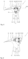
- Fig. 4 shows partial front view of the sleeper changer 1 with the first clamper 18 in the first position, or raised position.
- the first clamper 18 comprises a rail centering support 100.
- the centering support 100 comprises an opening 102, or cutout 102, arranged to be placed onto, and contact a rail, when a sleeper is mounted in the gripper 12 and the clamper 18 is in the second position.
- two pivotably arranged clamper arms 104 are arranged. The function of the clamper 18 will be discussed further in relation to Fig. 9 .
- Fig. 5 shows a side view of the sleeper changer 1 with the first clamper 18 in the first position, or the raised position and the beam 48 in a first position.
- the scissor mechanisms 56, 58 of the first clamper 18 may be actuated to move the first clamper 18 into the second position for engaging tension clamps of a sleeper.
- Fig. 6 shows a side view of the sleeper changer 1 with the first clamper 18 in the first position and the beam 48 rotated, or pivoted, and moved to a second position.
- the scissor mechanisms 56, 58 extension direction is aligned with the blade 14 of the sleeper changer 1, or the beam 48 has been rotated about 90 degrees, or 85-95 degrees in relation to the first position.
- the beam 48, the scissor mechanisms 56, 58 and the clamper 18 are both rotated and moved at the transition between, or to and from, the first position to the second position of the beam 48.
- Fig. 6 shows the gripper 12 arranged with contact elements 112 as well as stop 114.
- Fig. 7 shows a top view of the sleeper changer 1 with the beam 48 arranged in the second position and the clampers 18, 20 and scissor mechanisms in the first position, or raised position.
- Fig. 7 further shows the beam pivot axis 50 of the beam pivot axle 52 connecting the beam 48 to the base structure 16 relative to the beam axis 50.
- the beam axis 50 is parallel and offset transverse to the pivot axle 52.
- the blade 14 has two cutouts 116 arranged to receive a respective rail during ballast work using the blade 14.
- Fig. 8 shows a partial front view of the sleeper changer 1 with the beam 48 arranged in the second position and the and scissor mechanisms 56, 58 in the first position, or raised position.
- the first tension clamp 42 and the second tension clamp 44 contacts the rail 106 and locks, or secures, the sleeper 1087 to the rail 106.
- Fig. 9 further shows the beam actuator 54 that operatively connects the beam 48 to the base structure 16 to rotate the beam 48.
- Fig. 10 shows a cross-sectional partial view along A-A in Fig. 5 .
- the clamper arms 104 are arranged on opposite sides of the centering support 100.
- the clamper arms 104 are pivotally connected to the centering support 100 by a respective pivot 118.
- the pivots 118 are formed between the arms 104 and a connecting bar 120.
- An actuator 124 is operationally coupled to the arms 104.
- the actuator 124 is shown as a hydraulic actuator 124, such as a hydraulic cylinder 124.
- the arms 104 are pivoted around the pivots 118 and the opposite ends of the arms are moved inwards towards the rail, pushing the first tension clamp and the second tension clamp to lock, or secure, the rail to the sleeper.
- Fig. 10 further shows that the first clamper 18 is connected to the housing 82.
- Fig. 11 further shows the bearing housing 130 arranged around the sleeve protrusion, or collar.
- the sleeve protrusion 134 centers the bearing housing 130 around the sleeve and axle 120 that mounts the hydraulic cylinder 96 to the beam 48.
- Fig. 12 shows a first perspective view of an assembly 200 comprising the sleeper changer 1 and a rotor 202.
- Fig. 13 shows a side view of the assembly 200 of Fig. 12 .
- the rotor 202 is attached to the base structure 16 by the quick coupler 10.
- the rotor 202 shown is a tiltrotator 202.
- On the opposite end of the tiltrotator 202 relative the coupler that couples the tiltrotator 202 to the sleeper changer 1, the tiltrotator 202 has a further quick coupler 204 that can couple the assembly to an excavator arm.
- Fig. 14 shows a system 300 comprising the assembly 200 of Figs. 12-13 mounted to the excavator arm 304 of a wheeled excavator 302.
Landscapes
- Engineering & Computer Science (AREA)
- Architecture (AREA)
- Civil Engineering (AREA)
- Structural Engineering (AREA)
- Machines For Laying And Maintaining Railways (AREA)
Priority Applications (2)
| Application Number | Priority Date | Filing Date | Title |
|---|---|---|---|
| EP23202844.9A EP4538459A1 (fr) | 2023-10-10 | 2023-10-10 | Changeur de traverses |
| PCT/EP2024/078510 WO2025078498A1 (fr) | 2023-10-10 | 2024-10-10 | Changeur de traverse |
Applications Claiming Priority (1)
| Application Number | Priority Date | Filing Date | Title |
|---|---|---|---|
| EP23202844.9A EP4538459A1 (fr) | 2023-10-10 | 2023-10-10 | Changeur de traverses |
Publications (1)
| Publication Number | Publication Date |
|---|---|
| EP4538459A1 true EP4538459A1 (fr) | 2025-04-16 |
Family
ID=88373669
Family Applications (1)
| Application Number | Title | Priority Date | Filing Date |
|---|---|---|---|
| EP23202844.9A Withdrawn EP4538459A1 (fr) | 2023-10-10 | 2023-10-10 | Changeur de traverses |
Country Status (2)
| Country | Link |
|---|---|
| EP (1) | EP4538459A1 (fr) |
| WO (1) | WO2025078498A1 (fr) |
Citations (4)
| Publication number | Priority date | Publication date | Assignee | Title |
|---|---|---|---|---|
| WO1999024669A1 (fr) * | 1997-11-06 | 1999-05-20 | A. Rosenquist Förvaltnings Ab | Assemblage pour faire passer un dispositif de prehension d'une position d'assemblage a une position de relachement |
| KR101638849B1 (ko) * | 2015-08-31 | 2016-07-12 | 주식회사 우진 | 철도 침목 교체를 위한 일체형 집게 및 각도 조절 버켓장치 |
| CN108049266A (zh) * | 2017-12-13 | 2018-05-18 | 株洲时代电子技术有限公司 | 一种铁路换枕装置及其作业方法 |
| US20230279617A1 (en) * | 2022-03-03 | 2023-09-07 | Hoyt E. Dodd | E-Clip Installation Machine |
-
2023
- 2023-10-10 EP EP23202844.9A patent/EP4538459A1/fr not_active Withdrawn
-
2024
- 2024-10-10 WO PCT/EP2024/078510 patent/WO2025078498A1/fr active Pending
Patent Citations (4)
| Publication number | Priority date | Publication date | Assignee | Title |
|---|---|---|---|---|
| WO1999024669A1 (fr) * | 1997-11-06 | 1999-05-20 | A. Rosenquist Förvaltnings Ab | Assemblage pour faire passer un dispositif de prehension d'une position d'assemblage a une position de relachement |
| KR101638849B1 (ko) * | 2015-08-31 | 2016-07-12 | 주식회사 우진 | 철도 침목 교체를 위한 일체형 집게 및 각도 조절 버켓장치 |
| CN108049266A (zh) * | 2017-12-13 | 2018-05-18 | 株洲时代电子技术有限公司 | 一种铁路换枕装置及其作业方法 |
| US20230279617A1 (en) * | 2022-03-03 | 2023-09-07 | Hoyt E. Dodd | E-Clip Installation Machine |
Also Published As
| Publication number | Publication date |
|---|---|
| WO2025078498A1 (fr) | 2025-04-17 |
Similar Documents
| Publication | Publication Date | Title |
|---|---|---|
| US5722325A (en) | Tie guide and plate holding apparatus | |
| US9850624B2 (en) | Mobile automated tie replacement system | |
| WO1982002731A1 (fr) | Accouplement pour des outils de terrassement etc. | |
| US20070245603A1 (en) | Quick Coupler | |
| US4951573A (en) | Tie remover and inserter | |
| US8522688B2 (en) | Rail anchor spreader-squeezer | |
| US5284283A (en) | Rail processor | |
| CA1252455A (fr) | Outil a machoires jumelees pour l'extraction de tire-fonds | |
| KR101638849B1 (ko) | 철도 침목 교체를 위한 일체형 집게 및 각도 조절 버켓장치 | |
| CN216198162U (zh) | 一种机械臂及拱锚台车 | |
| US4579060A (en) | Tie exchanger with compound clamping head | |
| KR101848091B1 (ko) | 탬핑 머신 | |
| CS273312B2 (en) | Truck machine for rails' packing, levelling and straightening | |
| EP4538459A1 (fr) | Changeur de traverses | |
| US5651317A (en) | Railroad tie exchanger attachment | |
| CN1239784C (zh) | 滚轮式铁轨夹钳 | |
| US7025240B2 (en) | Apparatus and method for breaking rails | |
| US20080190633A1 (en) | Hydraulic Attachment for Skid Steer Loaders | |
| US12152349B2 (en) | Rail ballast management and tie guide ski for use with rail tie exchanger | |
| CS264278B2 (en) | Tamping aggregate for a packing machine | |
| EP0494257B1 (fr) | Marteau de demolition | |
| CN215149211U (zh) | 一种重型工件上下料堆垛机械手装置 | |
| US20240125085A1 (en) | Attachment with ground support member | |
| JPH05611A (ja) | 軌道用作業車 | |
| US6536354B1 (en) | Railway tie bed scarifier |
Legal Events
| Date | Code | Title | Description |
|---|---|---|---|
| PUAI | Public reference made under article 153(3) epc to a published international application that has entered the european phase |
Free format text: ORIGINAL CODE: 0009012 |
|
| STAA | Information on the status of an ep patent application or granted ep patent |
Free format text: STATUS: THE APPLICATION HAS BEEN PUBLISHED |
|
| AK | Designated contracting states |
Kind code of ref document: A1 Designated state(s): AL AT BE BG CH CY CZ DE DK EE ES FI FR GB GR HR HU IE IS IT LI LT LU LV MC ME MK MT NL NO PL PT RO RS SE SI SK SM TR |
|
| STAA | Information on the status of an ep patent application or granted ep patent |
Free format text: STATUS: THE APPLICATION IS DEEMED TO BE WITHDRAWN |
|
| 18D | Application deemed to be withdrawn |
Effective date: 20251017 |