EP4538532A2 - Scroll vacuum pump - Google Patents
Scroll vacuum pump Download PDFInfo
- Publication number
- EP4538532A2 EP4538532A2 EP25160041.7A EP25160041A EP4538532A2 EP 4538532 A2 EP4538532 A2 EP 4538532A2 EP 25160041 A EP25160041 A EP 25160041A EP 4538532 A2 EP4538532 A2 EP 4538532A2
- Authority
- EP
- European Patent Office
- Prior art keywords
- wall
- circular
- spiral
- vacuum pump
- groove
- Prior art date
- Legal status (The legal status is an assumption and is not a legal conclusion. Google has not performed a legal analysis and makes no representation as to the accuracy of the status listed.)
- Pending
Links
Images

Classifications
-
- F—MECHANICAL ENGINEERING; LIGHTING; HEATING; WEAPONS; BLASTING
- F04—POSITIVE - DISPLACEMENT MACHINES FOR LIQUIDS; PUMPS FOR LIQUIDS OR ELASTIC FLUIDS
- F04C—ROTARY-PISTON, OR OSCILLATING-PISTON, POSITIVE-DISPLACEMENT MACHINES FOR LIQUIDS; ROTARY-PISTON, OR OSCILLATING-PISTON, POSITIVE-DISPLACEMENT PUMPS
- F04C18/00—Rotary-piston pumps specially adapted for elastic fluids
- F04C18/02—Rotary-piston pumps specially adapted for elastic fluids of arcuate-engagement type, i.e. with circular translatory movement of co-operating members, each member having the same number of teeth or tooth-equivalents
- F04C18/0207—Rotary-piston pumps specially adapted for elastic fluids of arcuate-engagement type, i.e. with circular translatory movement of co-operating members, each member having the same number of teeth or tooth-equivalents both members having co-operating elements in spiral form
- F04C18/0215—Rotary-piston pumps specially adapted for elastic fluids of arcuate-engagement type, i.e. with circular translatory movement of co-operating members, each member having the same number of teeth or tooth-equivalents both members having co-operating elements in spiral form where only one member is moving
-
- F—MECHANICAL ENGINEERING; LIGHTING; HEATING; WEAPONS; BLASTING
- F04—POSITIVE - DISPLACEMENT MACHINES FOR LIQUIDS; PUMPS FOR LIQUIDS OR ELASTIC FLUIDS
- F04C—ROTARY-PISTON, OR OSCILLATING-PISTON, POSITIVE-DISPLACEMENT MACHINES FOR LIQUIDS; ROTARY-PISTON, OR OSCILLATING-PISTON, POSITIVE-DISPLACEMENT PUMPS
- F04C18/00—Rotary-piston pumps specially adapted for elastic fluids
- F04C18/02—Rotary-piston pumps specially adapted for elastic fluids of arcuate-engagement type, i.e. with circular translatory movement of co-operating members, each member having the same number of teeth or tooth-equivalents
- F04C18/0207—Rotary-piston pumps specially adapted for elastic fluids of arcuate-engagement type, i.e. with circular translatory movement of co-operating members, each member having the same number of teeth or tooth-equivalents both members having co-operating elements in spiral form
- F04C18/0246—Details concerning the involute wraps or their base, e.g. geometry
- F04C18/0269—Details concerning the involute wraps
-
- F—MECHANICAL ENGINEERING; LIGHTING; HEATING; WEAPONS; BLASTING
- F04—POSITIVE - DISPLACEMENT MACHINES FOR LIQUIDS; PUMPS FOR LIQUIDS OR ELASTIC FLUIDS
- F04C—ROTARY-PISTON, OR OSCILLATING-PISTON, POSITIVE-DISPLACEMENT MACHINES FOR LIQUIDS; ROTARY-PISTON, OR OSCILLATING-PISTON, POSITIVE-DISPLACEMENT PUMPS
- F04C23/00—Combinations of two or more pumps, each being of rotary-piston or oscillating-piston type, specially adapted for elastic fluids; Pumping installations specially adapted for elastic fluids; Multi-stage pumps specially adapted for elastic fluids
- F04C23/008—Hermetic pumps
-
- F—MECHANICAL ENGINEERING; LIGHTING; HEATING; WEAPONS; BLASTING
- F04—POSITIVE - DISPLACEMENT MACHINES FOR LIQUIDS; PUMPS FOR LIQUIDS OR ELASTIC FLUIDS
- F04C—ROTARY-PISTON, OR OSCILLATING-PISTON, POSITIVE-DISPLACEMENT MACHINES FOR LIQUIDS; ROTARY-PISTON, OR OSCILLATING-PISTON, POSITIVE-DISPLACEMENT PUMPS
- F04C25/00—Adaptations of pumps for special use of pumps for elastic fluids
- F04C25/02—Adaptations of pumps for special use of pumps for elastic fluids for producing high vacuum
-
- F—MECHANICAL ENGINEERING; LIGHTING; HEATING; WEAPONS; BLASTING
- F04—POSITIVE - DISPLACEMENT MACHINES FOR LIQUIDS; PUMPS FOR LIQUIDS OR ELASTIC FLUIDS
- F04C—ROTARY-PISTON, OR OSCILLATING-PISTON, POSITIVE-DISPLACEMENT MACHINES FOR LIQUIDS; ROTARY-PISTON, OR OSCILLATING-PISTON, POSITIVE-DISPLACEMENT PUMPS
- F04C2230/00—Manufacture
- F04C2230/60—Assembly methods
- F04C2230/602—Gap; Clearance
-
- F—MECHANICAL ENGINEERING; LIGHTING; HEATING; WEAPONS; BLASTING
- F04—POSITIVE - DISPLACEMENT MACHINES FOR LIQUIDS; PUMPS FOR LIQUIDS OR ELASTIC FLUIDS
- F04C—ROTARY-PISTON, OR OSCILLATING-PISTON, POSITIVE-DISPLACEMENT MACHINES FOR LIQUIDS; ROTARY-PISTON, OR OSCILLATING-PISTON, POSITIVE-DISPLACEMENT PUMPS
- F04C2230/00—Manufacture
- F04C2230/90—Improving properties of machine parts
- F04C2230/91—Coating
-
- F—MECHANICAL ENGINEERING; LIGHTING; HEATING; WEAPONS; BLASTING
- F04—POSITIVE - DISPLACEMENT MACHINES FOR LIQUIDS; PUMPS FOR LIQUIDS OR ELASTIC FLUIDS
- F04C—ROTARY-PISTON, OR OSCILLATING-PISTON, POSITIVE-DISPLACEMENT MACHINES FOR LIQUIDS; ROTARY-PISTON, OR OSCILLATING-PISTON, POSITIVE-DISPLACEMENT PUMPS
- F04C2250/00—Geometry
-
- F—MECHANICAL ENGINEERING; LIGHTING; HEATING; WEAPONS; BLASTING
- F04—POSITIVE - DISPLACEMENT MACHINES FOR LIQUIDS; PUMPS FOR LIQUIDS OR ELASTIC FLUIDS
- F04C—ROTARY-PISTON, OR OSCILLATING-PISTON, POSITIVE-DISPLACEMENT MACHINES FOR LIQUIDS; ROTARY-PISTON, OR OSCILLATING-PISTON, POSITIVE-DISPLACEMENT PUMPS
- F04C2270/00—Control; Monitoring or safety arrangements
- F04C2270/70—Safety, emergency conditions or requirements
- F04C2270/701—Cold start
-
- F—MECHANICAL ENGINEERING; LIGHTING; HEATING; WEAPONS; BLASTING
- F04—POSITIVE - DISPLACEMENT MACHINES FOR LIQUIDS; PUMPS FOR LIQUIDS OR ELASTIC FLUIDS
- F04C—ROTARY-PISTON, OR OSCILLATING-PISTON, POSITIVE-DISPLACEMENT MACHINES FOR LIQUIDS; ROTARY-PISTON, OR OSCILLATING-PISTON, POSITIVE-DISPLACEMENT PUMPS
- F04C28/00—Control of, monitoring of, or safety arrangements for, pumps or pumping installations specially adapted for elastic fluids
- F04C28/06—Control of, monitoring of, or safety arrangements for, pumps or pumping installations specially adapted for elastic fluids specially adapted for stopping, starting, idling or no-load operation
Definitions
- the movable spiral component can be moved along a circular path via the eccentric section of the drive shaft, which is why this movable spiral component, together with its carrier, is also referred to as an orbiter.
- This movable spiral component thus performs a so-called centrally symmetric oscillation relative to the fixed spiral component, which is also referred to as "orbiting" or "wobbling.”
- the fixed spiral component, together with its carrier is accordingly also referred to as a stator.
- a crescent-shaped volume enclosed between a wall in the corresponding groove migrates increasingly inward within the groove as the movable spiral component orbits.
- the process gas to be pumped is conveyed from a radially outer gas inlet of the pumping system radially inward to a gas outlet of the pumping system, particularly one located in a center.
- the pumping system of the scroll vacuum pump according to the invention comprises a circular part and a spiral part, with the spiral part being arranged radially within the circular part.
- Both the circular part and the spiral part extend from an inlet end to an outlet end, with the terms "inlet” and “outlet” being chosen with reference to the pumping direction of the fluid to be pumped.
- the outlet end of the circular part is connected to the inlet end of the spiral part, so that an effective pumping distance extends from the inlet end of the circular part to to the outlet end of the spiral part.
- the outlet end of the spiral part is arranged radially centrally in the pump system, whereby the inlet end of the spiral part is automatically arranged radially further outward than the outlet end of the spiral part.
- the sickle-shaped volumes described above are formed by a wall element that engages in a groove.
- a circular circular wall is provided for the circular part, and a spiral spiral wall is provided for the spiral part, both of which extend from an orbiter carrier which, as part of the movable spiral component, interacts with the drive shaft, in particular with the eccentric section.
- the circular wall usually does not describe a full circle of 360°, but only a partial circle, for example, encompassing between 300° and 345°.
- the spiral wall in turn, can often be mathematically described as an involute.
- a circular groove and a spiral groove are provided in the stator carrier of the stationary spiral component.
- the circular wall engages the circular groove
- the spiral wall engages the spiral groove in such a way that crescent-shaped volumes form between these components.
- these volumes are displaced radially further inward, resulting in the fluid being pumped from the inlet end of the circular part to its outlet end, then to the inlet end of the spiral part, and through the spiral part to its outlet end, preferably radially centered in the pump system.
- the minimum gap that can be set between the circular wall and a corresponding wall of the circular groove in the circular part varies depending on whether the circular wall forms the radially outer or the radially inner boundary of the gap.
- the minimum distance is smaller if the circular wall is located radially outward and larger if the circular wall forms the radially inner boundary of the gap.
- the radial position of the circular wall will change until a constant operating temperature is reached, with the radial position shifting radially outwards in particular.
- This radial position change also occurs relative to the circular groove, since the arrangement of the circular groove on the movable spiral component means that it heats up more than the circular groove on the stationary spiral component.
- the difference in the minimum distances radially inward and radially outward between the circular wall and the corresponding wall of the circular groove provided according to the invention makes it possible for the minimum distances that occur during continuous operation to be equalized on both sides of the circular wall. This makes it possible to set the smallest possible minimum distance on both sides of the circular wall in order to achieve good sealing of the correspondingly formed crescent-shaped volumes at their tapered ends and thus minimize pumping losses.
- Circular parts are significantly less complex to manufacture, since the elements of a circular part, in particular the circular wall and/or the circular groove, can be manufactured as turned parts, in contrast to the spiral wall and/or Spiral grooves that require complex milling.
- the pumping effect of the scroll vacuum pump according to the invention can be improved without excessively increasing the manufacturing effort.
- the coating can be single-layer or multi-layer. In other words, the entire coating can also consist of several individual coatings. In multi-layer coatings, the individual layers can be made of the same coating material. Alternatively, at least two of the coating layers used can be made of different materials.
- FIG. 3 are for the Fig. 1 , 2
- the scroll vacuum pump 10 shown comprises the spiral part 100 (Figure A), the circular part 200 (Figure B) and the further circular part 300 (Figure C), each along its extension between the inlet ends 102, 202, 302 (on the right in the figures) and their outlet ends 104, 204, 304 (on the left in the figures).
- the selected illustration shows, for each position along this extension, the minimum possible distances 130, 132, 134, 136, 230, 232, 330, 323, which are achieved with a corresponding relative positioning of the orbiter carrier 42 to the stator carrier 32 (cf. Fig. 1 , 2 ) can be assumed.
Landscapes
- Engineering & Computer Science (AREA)
- Mechanical Engineering (AREA)
- General Engineering & Computer Science (AREA)
- Applications Or Details Of Rotary Compressors (AREA)
- Rotary Pumps (AREA)
Abstract
Scrollvakuumpumpe (10) umfassend ein Pumpsystem (20), das ein feststehendes Spiralbauteil (30) und ein mit diesem pumpwirksam zusammenwirkendes bewegliches Spiralbauteil (40) umfasst, eine im Betrieb um eine Drehachse rotierenden Antriebswelle (22) mit einem Exzenterabschnitt (24) zum Antreiben des beweglichen Spiralbauteils (40), und einen elektrischen Antriebsmotor (24) für die Antriebswelle (22).In einem thermisch kalten Zustand des Pumpsystems (20) ist ein minimaler radialer Abstand (230) zwischen einer radial inneren Innenseite (214) einer Kreiswand (210) und einer radial inneren Innenwandung (222) einer Kreisnut (220) kleiner als ein minimaler radialer Abstand (232) zwischen einer radial äußeren Außenseite (214) der Kreiswand (210) und einer radial äußeren Außenwandung (224) der Kreisnut (220).A scroll vacuum pump (10) comprising a pumping system (20) comprising a stationary spiral component (30) and a movable spiral component (40) cooperating therewith for pumping, a drive shaft (22) rotating about a rotational axis during operation, said drive shaft having an eccentric section (24) for driving the movable spiral component (40), and an electric drive motor (24) for the drive shaft (22). In a thermally cold state of the pumping system (20), a minimum radial distance (230) between a radially inner inner side (214) of a circular wall (210) and a radially inner inner wall (222) of a circular groove (220) is smaller than a minimum radial distance (232) between a radially outer outer side (214) of the circular wall (210) and a radially outer outer wall (224) of the circular groove (220).
Description
Die vorliegende Offenbarung betrifft die Verbesserung von Scrollvakuumpumpen. Erfindungsgemäße Scrollvakuumpumpen umfassen ein Pumpsystem, das ein feststehendes Spiralbauteil und ein mit diesem pumpwirksam zusammenwirkendes bewegliches Spiralbauteil umfasst, eine im Betrieb um eine Drehachse rotierenden Antriebswelle mit einem Exzenterabschnitt zum Antreiben des beweglichen Spiralbauteils, und einen elektrischen Antriebsmotor für die Antriebswelle.The present disclosure relates to the improvement of scroll vacuum pumps. Scroll vacuum pumps according to the invention comprise a pumping system including a stationary scroll member and a movable scroll member cooperating therewith for pumping purposes, a drive shaft rotating about a rotational axis during operation, having an eccentric portion for driving the movable scroll member, and an electric drive motor for the drive shaft.
Scrollvakuumpumpen sind grundsätzlich bekannt, z.B. aus
Eine Scrollpumpe, insbesondere eine Scrollvakuumpumpen, ist eine gegen Atmosphärendruck verdichtende Verdrängerpumpe, die sich unter anderem als Kompressor einsetzen lässt. Eine Scrollvakuumpumpe kann zur Erzeugung eines Vakuums in einem Rezipienten verwendet werden, der an einen Gaseinlass der Scrollvakuumpumpe angeschlossen ist.A scroll pump, particularly a scroll vacuum pump, is a positive displacement pump that compresses against atmospheric pressure and can be used, among other things, as a compressor. A scroll vacuum pump can be used to create a vacuum in a chamber connected to a gas inlet of the scroll vacuum pump.
Scrollvakuumpumpen werden auch als Spiralvakuumpumpen oder Spiralfördereinrichtungen bezeichnet. Das einer Scrollvakuumpumpe zugrundeliegende Pumpprinzip ist aus dem Stand der Technik grundsätzlich bekannt. Ein feststehendes Spiralbauteil weist in einem Träger eine spiralförmige Nut auf, in die eine spiralförmige Wand eingreift, die an einem entsprechenden Träger des beweglichen Spiralbauteils angeordnet ist. Optional können zusätzlich auch kreisförmige Nuten im feststehenden Spiralbauteil und entsprechend kreisförmig ausgestaltete Wände im beweglichen Spiralbauteil vorgesehen sein, um eine Pumpwirkung zu verbessern. Die Spiralbauteile sind so ineinandergesteckt, dass sich durch die Wand des beweglichen Spiralbauteil in der Nut des feststehenden Spiralbauteil sichelförmige Volumina ausbilden, die auch als Taschen bezeichnet werden. Das bewegliche Spiralbauteil kann über den Exzenterabschnitt der Antriebswelle auf einer kreisförmigen Bahn bewegt werden, weshalb dieses bewegliche Spiralbauteil zusammen mit ihrem Träger auch als Orbiter bezeichnet wird. Dieses bewegliche Spiralbauteil führt somit relativ zum feststehenden Spiralbauteil eine sogenannte zentralsymmetrische Oszillation aus, was auch als "Orbitieren" oder "Wobbeln" bezeichnet wird. Das feststehende Spiralbauteil wird dementsprechend zusammen mit seinem Träger auch als Stator bezeichnet. Ein zwischen einer Wand in der entsprechenden Nut eingeschlossenes sichelförmiges Volumen wandert während des Orbitierens des beweglichen Spiralbauteils innerhalb der Nut zunehmend nach innen, wodurch mittels des wandernden Volumens das zu pumpende Prozessgas von einem radial außenliegenden Gaseinlass des Pumpsystems nach radial innen zu einem, insbesondere in einer Mitte befindlichen, Gasauslass des Pumpsystems gefördert wird.Scroll vacuum pumps are also known as spiral vacuum pumps or spiral conveying devices. The pumping principle underlying a scroll vacuum pump is generally known from the prior art. A stationary spiral component has a spiral groove in a support, into which a spiral wall engages. This spiral wall is arranged on a corresponding support of the movable spiral component. Optionally, circular grooves can also be provided in the stationary spiral component and correspondingly circular walls in the movable spiral component to improve the pumping effect. The spiral components are inserted into one another in such a way that crescent-shaped volumes, also known as pockets, are formed by the wall of the movable spiral component in the groove of the fixed spiral component. The movable spiral component can be moved along a circular path via the eccentric section of the drive shaft, which is why this movable spiral component, together with its carrier, is also referred to as an orbiter. This movable spiral component thus performs a so-called centrally symmetric oscillation relative to the fixed spiral component, which is also referred to as "orbiting" or "wobbling." The fixed spiral component, together with its carrier, is accordingly also referred to as a stator. A crescent-shaped volume enclosed between a wall in the corresponding groove migrates increasingly inward within the groove as the movable spiral component orbits. By means of the migrat-ing volume, the process gas to be pumped is conveyed from a radially outer gas inlet of the pumping system radially inward to a gas outlet of the pumping system, particularly one located in a center.
Der Exzenterantrieb, also die Antriebswelle mit dem Exzenterabschnitt, befindet sich innerhalb des Gehäuses der Scrollvakuumpumpe auf der zu diesen wandernden Volumina abgewandten Seite des Trägers und ist in der Praxis meistens von einer verformbaren Hülse, beispielsweise einem Wellbalg, umgeben, der einerseits zur Abdichtung des Antriebs gegenüber dem Ansaugbereich und andererseits als Drehsicherung für den Orbiter dient, da sich dieser anderenfalls, also ohne eine Drehsicherung, um sich selbst drehen könnte. Um diese Drehsicherung zu gewährleisten, kann beispielsweise die verformbare Hülse an einem ersten Ende mit dem Träger verbunden sein, wohingegen das dem ersten Ende gegenüberliegende zweite Ende der verformbaren Hülse mittels mehrerer Befestigungsmittel im Inneren des Gehäuses am Gehäusegrund verschraubt sein kann. Bekannte Scrollvakuumpumpen sind zumeist für einen Dauerbetrieb vorgesehen. Hierbei ist zu berücksichtigen, dass insbesondere zu Beginn des Betriebs der Scrollvakuumpumpe sich eine thermische Belastung insbesondere der Komponenten des Pumpsystems der Scrollvakuumpumpe ändert, da sich diese Komponenten erwärmen und sich erst nach einer gewissen Zeit eine stabile Temperaturverteilung im Pumpsystem einstellt.The eccentric drive, i.e. the drive shaft with the eccentric section, is located within the housing of the scroll vacuum pump on the side of the carrier facing away from the volumes moving there. In practice, it is usually surrounded by a deformable sleeve, for example a corrugated bellows, which serves on the one hand to seal the drive from the intake area and on the other hand to prevent the orbiter from rotating, as it could otherwise rotate around itself without a rotation lock. To ensure this rotation lock, for example, the deformable sleeve can be connected to the carrier at a first end, whereas the second end of the deformable sleeve, opposite the first end, can be screwed to the housing base by means of several fastening means inside the housing. Common scroll vacuum pumps are usually designed for continuous operation. It should be noted that, especially at the beginning of the scroll vacuum pump's operation, the thermal load changes, especially on the components of the scroll vacuum pump's pumping system, as these components heat up, and a stable temperature distribution in the pumping system only becomes established after a certain period of time.
Ausgehend von den voranstehend beschriebenen bekannten Scrollvakuumpumpen ist es daher Aufgabe der Erfindung, diese Scrollvakuumpumpen zu verbessern. Insbesondere ist es Aufgabe der Erfindung, eine hohe Pumpleistung der Scrollvakuumpumpe im Dauerbetrieb und/oder ein verbessertes Kaltstartverhalten derartiger Scrollvakuumpumpen zu ermöglichen.Based on the known scroll vacuum pumps described above, the object of the invention is therefore to improve these scroll vacuum pumps. In particular, the object of the invention is to enable a high pumping performance of the scroll vacuum pump in continuous operation and/or improved cold start behavior of such scroll vacuum pumps.
Die erfindungsgemäße Aufgabe wird durch die Patentansprüche gelöst. Insbesondere wird die Aufgabe durch eine Scrollvakuumpumpe gemäß Anspruch 1 gelöst. Weiterbildungen der erfindungsgemäßen Scrollvakuumpumpe ergeben sich aus den Unteransprüchen, der Beschreibung und den Zeichnungen.The object of the invention is achieved by the patent claims. In particular, the object is achieved by a scroll vacuum pump according to claim 1. Further developments of the scroll vacuum pump according to the invention emerge from the subclaims, the description, and the drawings.
Gemäß einem Aspekt der Erfindung wird die Aufgabe gelöst durch eine Scrollvakuumpumpe mit einem Pumpsystem, das ein feststehende Spiralbauteil und ein mit diesem pumpwirksam zusammenwirkendes bewegliches Spiralbauteil umfasst, einer im Betrieb um eine Drehachse rotierenden Antriebswelle mit einem Exzenterabschnitt zum Antreiben des beweglichen Spiralbauteils, und einem elektrischen Antriebsmotor für die Antriebswelle, wobei das bewegliche Spiralbauteil zusammen mit dem feststehenden Spiralbauteil einen kreisförmigen Kreisteil und einen radial innen an den Kreisteil anschließenden spiralförmigen Spiralteil bildet, wobei sich der Kreisteil und der Spiralteil jeweils von einem Einlassende zu einem Auslassende erstrecken und wobei das Auslassende des Kreisteils mit dem Einlassende des Spiralteils verbunden ist, wobei das bewegliche Spiralbauteil einen mit der Antriebswelle zusammenwirkenden Orbiterträger und das feststehende Spiralbauteil einen Statorträger aufweist, wobei der Spiralteil durch einen Eingriff einer sich ausgehend vom Orbiterträger erstreckenden spiralförmigen Spiralwand in eine im Statorträger angeordnete spiralförmige Spiralnut gebildet ist, und ferner der Kreisteil durch einen Eingriff einer sich ausgehend vom Orbiterträger erstreckenden kreisförmigen Kreiswand in eine im Statorträger angeordnete kreisförmige Kreisnut gebildet ist. Die erfindungsgemäße Scrollvakuumpumpe ist dadurch gekennzeichnet, dass in einem thermisch kalten Zustand des Pumpsystems ein minimaler radialer Abstand zwischen einer radial inneren Innenseite der Kreiswand und einer radial inneren Innenwandung der Kreisnut kleiner ist als ein minimaler radialer Abstand zwischen einer radial äußeren Außenseite der Kreiswand und einer radial äußeren Außenwandung der Kreisnut.According to one aspect of the invention, the object is achieved by a scroll vacuum pump with a pumping system comprising a stationary spiral component and a movable spiral component cooperating therewith in a pumping-effective manner, a drive shaft rotating about a rotational axis during operation and having an eccentric section for driving the movable spiral component, and an electric drive motor for the drive shaft, wherein the movable spiral component together with the stationary spiral component forms a circular circular part and a spiral spiral part adjoining the circular part radially inward, wherein the circular part and the spiral part each extend from an inlet end to an outlet end and wherein the outlet end of the circular part is connected to the inlet end of the spiral part, wherein the movable spiral component has an orbiter carrier cooperating with the drive shaft and the stationary The spiral component has a stator carrier, the spiral part being formed by engagement of a spiral spiral wall extending from the orbiter carrier into a spiral spiral groove arranged in the stator carrier, and the circular part being formed by engagement of a circular circular wall extending from the orbiter carrier into a circular circular groove arranged in the stator carrier. The scroll vacuum pump according to the invention is characterized in that, in a thermally cold state of the pump system, a minimum radial distance between a radially inner inside of the circular wall and a radially inner inner wall of the circular groove is smaller than a minimum radial distance between a radially outer outside of the circular wall and a radially outer outer wall of the circular groove.
Die erfindungsgemäße Scrollvakuumpumpe stellt eine Scrollvakuumpumpe mit einem wie vorab beschriebenen Pumpsystem dar. Das Pumpsystem weist insbesondere zwei Spiralbauteile auf, wobei eines der Spiralbauteile im Pumpsystem feststehend angeordnet ist, mit anderen Worten, während eines Betriebs der Scrollvakuumpumpe zur restlichen Scrollvakuumpumpe stationär bleibt. Das andere Spiralbauteil hingegen ist beweglich. Insbesondere ist das bewegliche Spiralbauteil mit einem Exzenterabschnitt der Antriebswelle mechanisch wirkverbunden, so dass dieses bewegliche Spiralbauteil, angetrieben durch den Antriebsmotor, die mit dem oben beschriebenen Orbitieren beziehungsweise Wobbeln verbundene Bewegung ausführt.The scroll vacuum pump according to the invention represents a scroll vacuum pump with a pumping system as described above. The pumping system has, in particular, two spiral components, one of which is fixedly arranged in the pumping system; in other words, it remains stationary relative to the rest of the scroll vacuum pump during operation of the scroll vacuum pump. The other spiral component, however, is movable. In particular, the movable spiral component is mechanically operatively connected to an eccentric section of the drive shaft, so that this movable spiral component, driven by the drive motor, executes the movement associated with the orbiting or wobbling described above.
Das Pumpsystem der erfindungsgemäßen Scrollvakuumpumpe umfasst einen Kreisteil und einen Spiralteil, wobei der Spiralteil radial innerhalb des Kreisteils angeordnet ist. Sowohl der Kreisteil als auch der Spiralteil erstrecken sich von einem Einlassende zu einem Auslassende, wobei die Begriffe "Einlass" und "Auslass" mit Bezug auf die Pumprichtung des zu fördernden Fluids gewählt sind. Das Auslassende des Kreisteils ist mit dem Einlassende des Spiralteils verbunden, so dass sich insgesamt eine effektive Pumpstrecke vom Einlassende des Kreisteils bis zum Auslassende des Spiralteils ergibt. Bevorzugt ist das Auslassende des Spiralteils radial mittig im Pumpsystem angeordnet, wodurch automatisch das Einlassende des Spiralteils radial weiter außen angeordnet ist als das Auslassende des Spiralteils.The pumping system of the scroll vacuum pump according to the invention comprises a circular part and a spiral part, with the spiral part being arranged radially within the circular part. Both the circular part and the spiral part extend from an inlet end to an outlet end, with the terms "inlet" and "outlet" being chosen with reference to the pumping direction of the fluid to be pumped. The outlet end of the circular part is connected to the inlet end of the spiral part, so that an effective pumping distance extends from the inlet end of the circular part to to the outlet end of the spiral part. Preferably, the outlet end of the spiral part is arranged radially centrally in the pump system, whereby the inlet end of the spiral part is automatically arranged radially further outward than the outlet end of the spiral part.
Sowohl im Kreisteil als auch im Spiralteil sind die oben beschriebenen sichelförmigen Volumina durch ein Wandelement gebildet, das in eine Nut eingreift. Für das Kreisteil ist eine kreisförmige Kreiswand und für das Spiralteil eine spiralförmige Spiralwand vorgesehen, die sich beide von einem Orbiterträger erstrecken, der als Teil des beweglichen Spiralbauteils mit der Antriebswelle, insbesondere mit dem Exzenterabschnitt, zusammenwirkt. Es ist zu beachten, dass die Kreiswand zumeist keinen Vollkreis von 360° beschreibt, sondern nur einen Teilkreis, zum Beispiel umfassend zwischen 300° und 345°. Die Spiralwand kann wiederum oftmals als eine Evolvente mathematisch beschrieben werden. Angepasst an die Ausführungen der Kreiswand und der Spiralwand sind im Statorträger des feststehenden Spiralbauteils entsprechend eine Kreisnut und eine Spiralnut vorgesehen.In both the circular part and the spiral part, the sickle-shaped volumes described above are formed by a wall element that engages in a groove. A circular circular wall is provided for the circular part, and a spiral spiral wall is provided for the spiral part, both of which extend from an orbiter carrier which, as part of the movable spiral component, interacts with the drive shaft, in particular with the eccentric section. It should be noted that the circular wall usually does not describe a full circle of 360°, but only a partial circle, for example, encompassing between 300° and 345°. The spiral wall, in turn, can often be mathematically described as an involute. Adapted to the designs of the circular wall and the spiral wall, a circular groove and a spiral groove are provided in the stator carrier of the stationary spiral component.
Im montierten Zustand des Pumpsystems greifen die Kreiswand in die Kreisnut und die Spiralwand in die Spiralnut derart ein, dass sich zwischen diesen Bauteilen die sichelförmigen Volumina bilden. Durch das Orbitieren des beweglichen Spiralbauteils, und damit der Kreiswand in der Kreisnut und der Spiralwand in der Spiralnut, verschieben sich diese Volumina radial immer weiter nach innen, wodurch im Ergebnis das zu pumpende Fluid vom Einlassende des Kreisteils zu dessen Auslassende, dann zum Einlassende des Spiralteils und durch das Spiralteil zu dessen Auslassende, bevorzugt radial mittig im Pumpsystem, gefördert wird.When the pump system is assembled, the circular wall engages the circular groove, and the spiral wall engages the spiral groove in such a way that crescent-shaped volumes form between these components. As the movable spiral component orbits, and thus the circular wall in the circular groove and the spiral wall in the spiral groove, these volumes are displaced radially further inward, resulting in the fluid being pumped from the inlet end of the circular part to its outlet end, then to the inlet end of the spiral part, and through the spiral part to its outlet end, preferably radially centered in the pump system.
Die Dimensionierung und insbesondere die Anordnung der Kreiswand und der Spiralwand relativ zur Kreisnut beziehungsweise zur Spiralnut ist derart gewählt, dass während eines Betriebs, insbesondere eines Dauerbetriebs, eine möglichst gute Pumpleistung erreicht werden kann. Dies kann unter anderem dadurch erreicht werden, dass ein minimaler Abstand zwischen jeweiligen Wand und den Wandungen der Nut, also zwischen Spiralwand und jeweils den beiden Wandungen der Spiralnut sowie zwischen Kreiswand und jeweils den beiden Wandungen der Kreisnut, möglichst klein ist. Dadurch kann eine gute Abdichtung der entsprechend gebildeten sichelförmigen Volumina an deren beiden zulaufenden Enden erreicht werden, wodurch Pumpverluste minimiert werden können.The dimensioning and in particular the arrangement of the circular wall and the spiral wall relative to the circular groove or the spiral groove is selected in such a way that during operation, in particular during continuous operation, the Good pumping performance can be achieved. This can be achieved, among other things, by keeping the distance between the respective wall and the walls of the groove, i.e., between the spiral wall and the two walls of the spiral groove, and between the circular wall and the two walls of the circular groove, as small as possible. This allows for good sealing of the correspondingly formed crescent-shaped volumes at their two tapered ends, thus minimizing pumping losses.
In diesem Zusammenhang wird darauf hingewiesen, dass die oben eingeführten minimalen Abstände bedingt durch das Orbitieren des beweglichen Spiralbauteils in Bezug auf den feststehenden Spiralbauteil nicht ortsfest lokalisiert sind, sondern sowohl in der Spiralbahn als auch in der Kreisbahn von dem jeweiligen Einlassende in Richtung des Auslassendes wandern. Ein "minimaler Abstand" im Sinne der vorliegenden Erfindung stellt somit jeweils einen Abstand zwischen einer Wand und einer Wandung einer Nut dar, dessen Wert durch eine entsprechende relative Positionierung der Wand zur Wandung minimiert ist. Dies kann allgemein ohne Angabe einer spezifischen Position erfolgen, so dass dann der minimale Abstand über die gesamte Erstreckung der jeweiligen Wand in der Nut beschrieben ist. Alternativ kann die Angabe eines "minimalen Abstands" auch mit einer derartigen Positionsangabe erfolgen, beispielsweise "am Einlassende" oder "am Auslassende". In diesem Fall bezeichnet der "minimale Abstand" jeweils explizit den kleinsten annehmbaren Wert an dieser Position.In this context, it should be noted that the minimum distances introduced above are not fixed in place due to the orbiting of the movable spiral component with respect to the stationary spiral component, but rather move in both the spiral path and the circular path from the respective inlet end toward the outlet end. A "minimum distance" within the meaning of the present invention thus represents a distance between a wall and a wall of a groove, the value of which is minimized by a corresponding relative positioning of the wall to the wall. This can generally be done without specifying a specific position, so that the minimum distance is then described over the entire extent of the respective wall in the groove. Alternatively, the specification of a "minimum distance" can also be made with such a position specification, for example, "at the inlet end" or "at the outlet end." In this case, the "minimum distance" explicitly refers to the smallest acceptable value at this position.
Wie voranstehend bereits ausgeführt, befindet sich das Pumpsystem im Dauerbetrieb in einem thermisch stabilen Zustand, wobei sich die Komponenten des Pumpsystems bis zum Erreichen dieses Zustands erwärmen. Durch diese Erwärmung kommt es zu einer Änderung der relativen Position der Spiralwand in der Spiralnut und der Kreiswand in der Kreisnut. Diese Änderung ist umso größer, je weiter radial außen sich ein betrachteter Abschnitt der jeweilige Wand befindet, und je größer eine Temperaturänderung ausfällt. Im Wesentlichen folgt eine Änderung der radialen Position (dr) einer jeweiligen Wand folgender Formel: ![]()
![]()
Es ist zu beachten, dass diese Formel den einfachen Fall beschreibt, wenn der Orbiterträger und der Statorträger, insbesondere zumindest jedoch die Spiralwand und die Kreiswand sowie die Spiralnut und die Kreisnut aus dem selben Material gefertigt sind. Bei unterschiedlichen Materialien für diese Bauelemente, die zumeist dann auch ein jeweils verschiedenes Ausdehnungsverhalten zeigen, wird obige Formel komplexer, um diesem Umstand Rechnung zu tragen.It should be noted that this formula describes the simple case where the orbiter carrier and the stator carrier, and in particular at least the spiral wall and the circular wall, as well as the spiral groove and the circular groove, are made of the same material. When different materials are used for these components, which usually also exhibit different expansion behaviors, the above formula becomes more complex to account for this circumstance.
Erfindungsgemäß hat sich als besonders vorteilhaft herausgestellt, wenn in einem thermisch kalten Zustand des Pumpsystems ein minimaler radialer Abstand zwischen einer radial inneren Innenseite der Kreiswand und einer radial inneren Innenwandung der Kreisnut kleiner ist als ein minimaler radialer Abstand zwischen einer radial äußeren Außenseite der Kreiswand und einer radial äußeren Außenwandung der Kreisnut. Ein thermisch kalter Zustand im Sinne der Erfindung ist insbesondere ein Montagezustand beziehungsweise Kaltzustand der Scrollvakuumpumpe. Die Scrollvakuumpumpe ist in ihrem thermisch kalten Zustand noch nicht in Betrieb, und war insbesondere zuvor auch derart lange nicht in Betrieb, dass die Komponenten des Pumpsystems wieder vollständig abgekühlt sind. Mit anderen Worten, im ausgeschalteten und abgekühlten Zustand der erfindungsgemäßen Scrollvakuumpumpe ist im Kreisteil der minimale Spalt, der sich zwischen der Kreiswand und einer entsprechenden Wandung der Kreisnut eingestellt werden kann, unterschiedlich, je nachdem ob die Kreiswand die radial äußere oder die radial innere Begrenzung des Spalts bildet. Der minimale Abstand ist kleiner, wenn die Kreiswand radial außen liegt, und größer, wenn die Kreiswand die radial innere Begrenzung des Spalts ausformt.According to the invention, it has been found to be particularly advantageous if, in a thermally cold state of the pump system, a minimum radial distance between a radially inner inner side of the circular wall and a radially inner inner wall of the circular groove is smaller than a minimum radial distance between a radially outer outside of the circular wall and a radially outer outer wall of the circular groove. A thermally cold state within the meaning of the invention is, in particular, an assembled state or cold state of the scroll vacuum pump. In its thermally cold state, the scroll vacuum pump is not yet in operation and, in particular, has not been in operation for such a long time beforehand that the components of the pump system have completely cooled down again. In other words, in the switched-off and cooled-down state of the scroll vacuum pump according to the invention, the minimum gap that can be set between the circular wall and a corresponding wall of the circular groove in the circular part varies depending on whether the circular wall forms the radially outer or the radially inner boundary of the gap. The minimum distance is smaller if the circular wall is located radially outward and larger if the circular wall forms the radially inner boundary of the gap.
Entsprechend der obigen Formel wird sich eine radiale Position der Kreiswand bis zum Erreichen einer konstanten Betriebstemperatur ändern, wobei insbesondere eine Verlagerung der radialen Position nach radial außen erfolgt. Diese radiale Positionsänderung erfolgt insbesondere auch relativ zur Kreisnut, da durch die Anordnung der Kreisnut auf dem beweglichen Spiralbauteil diese sich relativ zur Kreisnut auf dem feststehenden Spiralbauteil mehr erwärmt. Durch die erfindungsgemäß vorgesehenen Unterschied in den minimalen Abständen radial innen beziehungsweise radial außen zwischen der Kreiswand und der entsprechenden Wandung der Kreisnut kann ermöglicht werden, dass sich die minimalen Abstände, die sich während eines Dauerbetriebs einstellen, auf beiden Seiten der Kreiswand angleichen. Dies ermöglicht, auf beiden Seiten der Kreiswand einen insgesamt möglichst geringen minimalen Abstand einzustellen, um eine gute Abdichtung der entsprechend gebildeten sichelförmigen Volumina an deren zulaufenden Enden zu erreichen und dadurch Pumpverluste zu minimieren.According to the above formula, the radial position of the circular wall will change until a constant operating temperature is reached, with the radial position shifting radially outwards in particular. This radial position change also occurs relative to the circular groove, since the arrangement of the circular groove on the movable spiral component means that it heats up more than the circular groove on the stationary spiral component. The difference in the minimum distances radially inward and radially outward between the circular wall and the corresponding wall of the circular groove provided according to the invention makes it possible for the minimum distances that occur during continuous operation to be equalized on both sides of the circular wall. This makes it possible to set the smallest possible minimum distance on both sides of the circular wall in order to achieve good sealing of the correspondingly formed crescent-shaped volumes at their tapered ends and thus minimize pumping losses.
Gemäß einer Weiterbildung kann bei der erfindungsgemäßen Scrollvakuumpumpe vorgesehen sein, dass in einem thermisch kalten Zustand des Pumpsystems ein minimaler radialer Abstand zwischen der Innenseite der Spiralwand und der Innenwandung der Spiralnut am Einlassende des Spiralteils kleiner ist als ein minimaler radialer Abstand zwischen der Innenseite der Kreiswand und der Innenwandung der Kreisnut am Auslassende des Kreisteils.According to a further development, it can be provided in the scroll vacuum pump according to the invention that, in a thermally cold state of the pump system, a minimum radial distance between the inner side of the spiral wall and the inner wall of the spiral groove at the inlet end of the spiral part is smaller than a minimum radial distance between the inner side of the circular wall and the inner wall of the circular groove at the outlet end of the circular part.
Wie oben bereits ausgeführt ist bei einer Erwärmung des Pumpsystems, und hier insbesondere des beweglichen Spiralbauteils, eine radiale Positionsverschiebung der Spiralwand und der Kreiswand zu erwarten, gemäß der oben angegebenen Formel insbesondere um so mehr, je weiter radial außen sich ein Abschnitt der jeweiligen Wand befindet. Ausgehend hiervon wäre anzunehmen, dass der minimale radiale Abstand zwischen der Innenseite der Spiralwand und der Innenwandung der Spiralnut am Einlassende des Spiralteils größer eingestellt werden sollte als der minimale radiale Abstand zwischen der Innenseite der Kreiswand und der Innenwandung der Kreisnut am Auslassende des Kreisteils. Es hat sich jedoch überraschenderweise herausgestellt, dass dies beim Kaltstart des Pumpsystems, also bei einem Beginn des Betriebs, zu Berührungen zwischen der Kreiswand und der Innenwandung der Kreisnut führt beziehungsweise führen kann. Eine solche Berührung wird auch als Anlaufen oder als Anlauf bezeichnet. Durch den in dieser Ausgestaltung vorgesehenen minimalen Abstand zwischen der Innenseite der Spiralwand und der radial innerhalb angeordneten Innenwandung der Spiralnut mit einem kleineren Wert als der minimale Abstand zwischen der Kreiswand und der radial innerhalb angeordneten Innenwandung der Kreisnut kann dieses sogenannte Anlaufen der Kreiswand an der Innenwandung der Kreisnut vermieden werden. Insgesamt kann auf diese Weise ein Kaltstartverhalten der erfindungsgemäßen Scrollvakuumpumpe verbessert werden.As already explained above, when the pump system, and in particular the movable spiral component, heats up, a radial positional shift of the spiral wall and the circular wall is to be expected. According to the formula given above, this shift is particularly greater the further radially outward a section of the respective wall is located. Based on this, it would be assumed that the minimum radial distance between the inner side of the spiral wall and the inner wall of the spiral groove at the inlet end of the spiral section should be set larger. as the minimum radial distance between the inside of the circular wall and the inner wall of the circular groove at the outlet end of the circular part. However, it has surprisingly been found that this leads or can lead to contact between the circular wall and the inner wall of the circular groove during a cold start of the pump system, i.e. at the start of operation. Such contact is also referred to as start-up or start-up. By providing a minimum distance between the inside of the spiral wall and the radially inner inner wall of the spiral groove in this embodiment, with a smaller value than the minimum distance between the circular wall and the radially inner inner wall of the circular groove, this so-called start-up of the circular wall on the inner wall of the circular groove can be avoided. Overall, the cold start behavior of the scroll vacuum pump according to the invention can be improved in this way.
Es wird darauf hingewiesen, dass im voranstehend beschriebenen Ausgestaltungsbeispiel der minimale Abstand zwischen der Innenseite der Spiralwand und der radial innerhalb angeordneten Innenwandung der Spiralnut im thermisch kalten Zustand des Pumpsystems bevorzugt auf die erreichbare Pumpleistung im Dauerbetrieb optimiert sein kann. Mit anderen Worten, die radiale Position der Spiralwand wird insbesondere unter Berücksichtigung dieser Vorgaben bezüglich der zu erreichenden Pumpleistung festgelegt, und basierend hierauf dann die radiale Position der Kreiswand entsprechend angepasst.It should be noted that in the exemplary embodiment described above, the minimum distance between the inner side of the spiral wall and the radially inner inner wall of the spiral groove in the thermally cold state of the pump system can preferably be optimized for the achievable pumping performance in continuous operation. In other words, the radial position of the spiral wall is determined, particularly taking into account these specifications regarding the pumping performance to be achieved, and based on this, the radial position of the circular wall is then adjusted accordingly.
Darüber hinaus kann die erfindungsgemäße Scrollvakuumpumpe auch dadurch gekennzeichnet sein, dass in einem thermisch kalten Zustand des Pumpsystems der minimale radiale Abstand zwischen der Innenseite der Spiralwand und der Innenwandung der Spiralnut im Spiralteil vom Einlassende hin zum Auslassende zunimmt. Gemäß der oben angegebenen Formel ist die erwartete Änderung einer radialen Position der Spiralwand insbesondere umso größer, je weiter radial außen sich ein Abschnitt der Spiralwand befindet. Da sich die Spiralwand spiralförmig vom radial weiter außen angeordneten Einlassende des Spiralteils bis zum radial weiter innen, bevorzugt radial mittig, positionierten Auslassende des Spiralteils erstreckt, weist die Spiralwand je nach betrachtetem Abschnitt verschiedene Radien auf, wodurch wiederum unterschiedlich große Änderungen der jeweiligen radialen Position der Spiralwand zu erwarten sind. Insbesondere ist zu erwarten, dass die Änderungen vom Einlassende hin zum Auslassende abnehmen. Durch die vorgesehene Zunahme des minimalen radialen Abstand zwischen der Innenseite der Spiralwand und der Innenwandung der Spiralnut im Spiralteil vom Einlassende hin zum Auslassende kann dies kompensiert werden, bevorzugt derart, dass sich im Dauerbetrieb ein über die gesamte Erstreckung der Spiralwand konstanter minimaler Abstand einstellt. Dies ermöglicht insbesondere Pumpverluste zu minimieren.Furthermore, the scroll vacuum pump according to the invention can also be characterized in that, in a thermally cold state of the pumping system, the minimum radial distance between the inner side of the spiral wall and the inner wall of the spiral groove in the spiral part increases from the inlet end to the outlet end. According to the formula given above, the expected change in the radial position of the spiral wall is particularly greater the further radially outward a section of the spiral wall is located. Since the spiral wall is spirally from the inlet end of the spiral part, which is arranged radially further outwards, to the outlet end of the spiral part, which is positioned radially further inwards, preferably radially centrally, the spiral wall has different radii depending on the section under consideration, which in turn means that changes of different sizes in the respective radial position of the spiral wall are to be expected. In particular, it is to be expected that the changes decrease from the inlet end to the outlet end. This can be compensated for by the intended increase in the minimum radial distance between the inside of the spiral wall and the inner wall of the spiral groove in the spiral part from the inlet end to the outlet end, preferably in such a way that a constant minimum distance is established over the entire extent of the spiral wall during continuous operation. This makes it possible, in particular, to minimize pumping losses.
In einer bevorzugten Ausgestaltung der erfindungsgemäßen Scrollvakuumpumpe kann beispielsweise der minimale radiale Abstand zwischen der Innenseite der Spiralwand und der Innenwandung der Spiralnut im Spiralteil vom Einlassende auf hin zum Auslassende stetig zunehmen, bevorzugt linear zunehmen.In a preferred embodiment of the scroll vacuum pump according to the invention, for example, the minimum radial distance between the inner side of the spiral wall and the inner wall of the spiral groove in the spiral part can increase continuously, preferably linearly, from the inlet end to the outlet end.
Auch kann bei der erfindungsgemäßen Scrollvakuumpumpe ferner vorgesehen sein, dass das bewegliche Spiralbauteil zusammen mit dem feststehenden Spiralbauteil zumindest einen sich radial außen an den Kreisteil anschließenden und mit diesem verbundenen weiteren kreisförmigen Kreisteil bilden, wobei sich der weitere Kreisteil von einem Einlassende zu einem Auslassende erstreckt und durch einen Eingriff einer sich ausgehend vom Orbiterträger erstreckenden weiteren kreisförmigen Kreiswand in eine im Statorträger angeordnete weitere kreisförmige Kreisnut gebildet ist. Die wesentliche Pumpwirkung der Scrollvakuumpumpe wird durch den Spiralteil bereitgestellt, wobei das vorhandene eine Kreisteil unterstützend wirkt. Kreisteile sind jedoch deutlich weniger aufwändig in der Herstellung, da die Elemente eines Kreisteils, insbesondere die Kreiswand und/oder die Kreisnut, als Drehteile gefertigt werden können, im Gegensatz zur Spiralwand und/oder Spiralnut, die aufwändig gefräst werden müssen. Durch das Vorsehen eines weiteren Kreisteils kann somit die Pumpwirkung der damit ausgestatteten erfindungsgemäßen Scrollvakuumpumpe verbessert werden, ohne den Herstellungsaufwand übermäßig zu steigern.In the scroll vacuum pump according to the invention, it can also be further provided that the movable spiral component, together with the stationary spiral component, form at least one further circular circular part radially adjoining the circular part and connected thereto, wherein the further circular part extends from an inlet end to an outlet end and is formed by the engagement of a further circular circular wall extending from the orbiter carrier into a further circular circular groove arranged in the stator carrier. The essential pumping action of the scroll vacuum pump is provided by the spiral part, with the existing one circular part having a supporting effect. Circular parts, however, are significantly less complex to manufacture, since the elements of a circular part, in particular the circular wall and/or the circular groove, can be manufactured as turned parts, in contrast to the spiral wall and/or Spiral grooves that require complex milling. By providing an additional circular section, the pumping effect of the scroll vacuum pump according to the invention can be improved without excessively increasing the manufacturing effort.
In einer weiteren Ausgestaltungsform der erfindungsgemäßen Scrollvakuumpumpe kann ferner vorgesehen sein, dass die Einlassenden und die Auslassenden des Kreisteils und des weiteren Kreisteils jeweils verbunden sind und dadurch der Kreisteil und der weitere Kreisteil parallel geschaltet sind, oder wobei das Auslassende des weiteren Kreisteils mit dem Einlassende des Kreisteils verbunden ist und dadurch der Kreisteil und der weitere Kreisteil seriell geschaltet sind. Durch eine Parallelschaltung der Kreisteile kann insgesamt ein Pumpvolumen erhöht werden. Durch eine Seriellschaltung wiederum kann eine durch das gesamte Pumpsystem erreichbare Kompression gesteigert werden. Je nach Anforderung kann somit die erfindungsgemäße Scrollvakuumpumpe entsprechend ausgebildet sein.In a further embodiment of the scroll vacuum pump according to the invention, it can further be provided that the inlet ends and the outlet ends of the circular part and of the further circular part are each connected, thereby connecting the circular part and the further circular part in parallel, or wherein the outlet end of the further circular part is connected to the inlet end of the circular part, thereby connecting the circular part and the further circular part in series. By connecting the circular parts in parallel, the overall pumping volume can be increased. By connecting them in series, the compression achievable by the entire pumping system can be increased. Depending on requirements, the scroll vacuum pump according to the invention can thus be designed accordingly.
Es wird darauf hingewiesen, das bei einem Vorhandensein von mehreren weiteren Kreisteilen auch Kombinationen aus Parallelschaltung und Seriellschaltung einzelner Kreisteile möglich sind.It should be noted that if there are several additional circuit sections, combinations of parallel connection and series connection of individual circuit sections are also possible.
Weiter kann die erfindungsgemäße Scrollvakuumpumpe dahingehend ausgebildet sein, dass in einem thermisch kalten Zustand des Pumpsystems in dem weiteren Kreisteil ein minimaler radialer Abstand zwischen einer radialen Innenseite der weiteren Kreiswand und einer radial inneren Innenwandung der weiteren Kreisnut kleiner ist als ein minimaler radialer Abstand zwischen einer radialen Außenseite der weiteren Kreiswand und einer radial äußeren Außenwandung der weiteren Kreisnut. Auch die Kreiswand des weiteren Kreisteils erfährt zu Beginn des Betriebs eine Erwärmung, und folglich wird sich bis zum Erreichen des temperaturstabilen Dauerbetriebs auch die radiale Position dieser Kreiswand nach radial außen verschieben. In dieser Ausgestaltungsform sind die relativen minimalen Abstände im weiteren Kreisteil zwischen der Kreiswand und der Innen- beziehungsweise Außenwandung der Kreisnut analog zum bereits oben beschriebenen Kreisteil ausgebildet. Sämtliche Vorteile, die voranstehend bezüglich dieser Ausgestaltung des Kreisteils beschrieben wurden, können auch durch eine entsprechende Ausgestaltung des weiteren Kreisteils für dieses weitere Kreisteil ermöglicht werden. Insbesondere kann erreicht werden, Pumpverluste zu minimieren.Furthermore, the scroll vacuum pump according to the invention can be designed such that, in a thermally cold state of the pump system in the further circular part, a minimum radial distance between a radial inner side of the further circular wall and a radially inner inner wall of the further circular groove is smaller than a minimum radial distance between a radial outer side of the further circular wall and a radially outer wall of the further circular groove. The circular wall of the further circular part also experiences heating at the beginning of operation, and consequently, until temperature-stable continuous operation is reached, the radial position of this circular wall will also change radially outward. In this embodiment, the relative minimum distances in the wider circular section between the circular wall and the inner or outer wall of the circular groove are designed analogously to the circular section already described above. All of the advantages described above with regard to this design of the circular section can also be achieved for this further circular section by a corresponding design of the further circular section. In particular, pumping losses can be minimized.
Ferner kann die erfindungsgemäße Scrollvakuumpumpe auch dadurch gekennzeichnet sein, dass in einem thermisch kalten Zustand des Pumpsystems der minimale radiale Abstand zwischen der Innenseite der Kreiswand und der Innenwandung der Kreisnut und der minimale radiale Abstand zwischen der Innenseite der weiteren Kreiswand und der Innenwandung der weiteren Kreisnut gleich sind. Wie voranstehend ausgeführt, kann der minimale Abstand zwischen Kreiswand und Innenwandung der Kreisnut bei dem Kreisteil, der radial anschließend an den Spiralteil angeordnet ist, derart gewählt sein, dass ein Anlaufen der Kreiswand an der Innenwandung der Kreisnut vermieden werden kann. Der für diesen Kreisteil eingestellte minimale Abstand ist somit genau ausreichend, um dieses Anlaufen zu verhindern. Daher kann es vorteilhaft sein, auch den minimalen Abstand zwischen Innenseite der Kreiswand und Innenwandung der Kreisnut im weiteren Kreisteil entsprechend einzustellen, insbesondere auf denselben Wert. Aufwändige Versuchsreihen zum Ermitteln des einzustellenden minimalen Abstands für den weiteren Kreisteil zum Verhindern eines Anlaufens können so vermieden werden.Furthermore, the scroll vacuum pump according to the invention can also be characterized in that, in a thermally cold state of the pump system, the minimum radial distance between the inner side of the circular wall and the inner wall of the circular groove and the minimum radial distance between the inner side of the further circular wall and the inner wall of the further circular groove are the same. As explained above, the minimum distance between the circular wall and the inner wall of the circular groove in the circular part arranged radially adjacent to the spiral part can be selected such that contact of the circular wall with the inner wall of the circular groove can be avoided. The minimum distance set for this circular part is thus precisely sufficient to prevent this contact. It can therefore be advantageous to also set the minimum distance between the inner side of the circular wall and the inner wall of the circular groove in the further circular part accordingly, in particular to the same value. Complex test series to determine the minimum distance to be set for the further circular part to prevent contact can thus be avoided.
Auch kann die erfindungsgemäße Scrollvakuumpumpe dahingehend weitergebildet sein, dass in einem thermisch kalten Zustand des Pumpsystems der minimale radiale Abstand zwischen der Außenseite der Kreiswand und der Außenwandung der Kreisnut und der minimale radiale Abstand zwischen der Außenseite der weiteren Kreiswand und der Außenwandung der weiteren Kreisnut unterschiedlich sind.The scroll vacuum pump according to the invention can also be further developed such that in a thermally cold state of the pump system, the minimum radial distance between the outer side of the circular wall and the outer wall of the circular groove and the minimum radial distance between the outer side of the further circular wall and the outer wall of the further circular groove are different.
In der zuvor beschriebene Ausgestaltungsform der erfindungsgemäßen Scrollvakuumpumpe sind die jeweils radial inneren Abstände zwischen den jeweiligen Innenseiten der Kreiswände und den jeweiligen Innenwandungen der Kreisnuten gleich ausgebildet. Da sich die Kreisteile, der zumindest eine Kreisteil und der weitere Kreisteil, auf verschiedenen radialen Positionen befinden und somit einen unterschiedlichen Radius aufweisen, kann es jedoch vorteilhaft sein, die gemäß obiger Formel zu erwartende unterschiedliche Änderung der radialen Position der jeweiligen Kreiswand bei Erwärmung zu berücksichtigen, um beispielsweise die bereits beschriebene Angleichung der minimalen Abstände zwischen der jeweiligen Kreiswand und der Innen- beziehungsweise Außenwandung der jeweiligen Kreisnut zu erreichen. Durch die in dieser Ausgestaltung vorgeschlagene Ausgestaltung mit unterschiedlichen minimalen radialen Abständen zwischen der Außenseite der jeweiligen Kreiswand und der Außenwandung der jeweiligen Kreisnut kann dies, alternativ oder zusätzlich zu gleichen minimalen Abständen auf der radialen Innenseite der jeweiligen Kreiswand, ermöglicht werden.In the previously described embodiment of the scroll vacuum pump according to the invention, the respective radially inner distances between the respective inner sides of the circular walls and the respective inner walls of the circular grooves are of the same design. Since the circular parts, the at least one circular part and the further circular part, are located at different radial positions and thus have a different radii, it can be advantageous, however, to take into account the different changes in the radial position of the respective circular wall upon heating, which can be expected according to the above formula, in order, for example, to achieve the already described equalization of the minimum distances between the respective circular wall and the inner or outer wall of the respective circular groove. The design proposed in this embodiment with different minimum radial distances between the outer side of the respective circular wall and the outer wall of the respective circular groove can make this possible, as an alternative to or in addition to identical minimum distances on the radially inner side of the respective circular wall.
Gemäß einer Weiterbildung der erfindungsgemäßen Scrollvakuumpumpe kann ferner vorgesehen sein, dass in einem thermisch kalten Zustand des Pumpsystems der minimale radiale Abstand zwischen der Außenseite der Kreiswand und der Außenwandung der Kreisnut kleiner ist als der minimale radiale Abstand zwischen der Außenseite der weiteren Kreiswand und der Außenwandung der weiteren Kreisnut. Der weitere Kreisteil ist radial außerhalb des bereits vorhandenen Kreisteils angeordnet, weist also insbesondere einen größeren Radius auf. Dies führt gemäß der oben angegebenen Formel zu einer größeren zu erwartenden Änderung des Radius bei einem Kaltstart bis zum Erreichen des Dauerbetriebs. Durch einen größeren minimalen Abstand im weiteren Kreisteil auf der radial äußeren Seite der Kreiswand, also zwischen der radial äußeren Außenseite der Kreiswand und der radial äußeren Außenwandung der Kreisnut, kann dies kompensiert werden, um dennoch eine Angleichung der minimalen Abstände im weiteren Kreisteil radial innen und radial außen zwischen der Kreiswand und der Innen- beziehungsweise Außenwandung der Kreisnut zu erhalten.According to a further development of the scroll vacuum pump according to the invention, it can further be provided that, in a thermally cold state of the pump system, the minimum radial distance between the outer side of the circular wall and the outer wall of the circular groove is smaller than the minimum radial distance between the outer side of the further circular wall and the outer wall of the further circular groove. The further circular part is arranged radially outside the already existing circular part, thus in particular has a larger radius. According to the formula given above, this leads to a larger expected change in the radius during a cold start until continuous operation is reached. This can be compensated by a larger minimum distance in the further circular part on the radially outer side of the circular wall, i.e. between the radially outer outside of the circular wall and the radially outer wall of the circular groove, in order to nevertheless achieve an adjustment of the minimum distances in the to obtain a further circular part radially inside and radially outside between the circular wall and the inner or outer wall of the circular groove.
Auch kann ferner bei der erfindungsgemäßen Scrollvakuumpumpe vorgesehen sein, dass in einem thermisch kalten Zustand des Pumpsystems im Kreisteil zwischen dem Einlassende und dem Auslassende der minimale radiale Abstand zwischen der Innenseite der Kreiswand und der Innenwandung der Kreisnut konstant ist, und/oder dass in einem thermisch kalten Zustand des Pumpsystems in dem weiteren Kreisteil zwischen dem Einlassende und dem Auslassende der minimale radiale Abstand zwischen der Innenseite der weiteren Kreiswand und der Innenwandung der weiteren Kreisnut konstant ist.Furthermore, in the scroll vacuum pump according to the invention, it can be provided that in a thermally cold state of the pumping system in the circular part between the inlet end and the outlet end, the minimum radial distance between the inside of the circular wall and the inner wall of the circular groove is constant, and/or that in a thermally cold state of the pumping system in the further circular part between the inlet end and the outlet end, the minimum radial distance between the inside of the further circular wall and the inner wall of the further circular groove is constant.
Kreisteile weisen als kreisförmige Elemente einen jeweils konstanten Radius auf. Daher ist gemäß der oben angegebenen Formel, eine gleichmäßige Temperatur vorausgesetzt, auch eine über das gesamte jeweilige Kreisteil konstante Änderung der radialen Position zu erwarten. Durch über eine gesamte Erstreckung der jeweiligen Kreiswand konstanten minimalen Abstand zwischen einer Innenseite der Kreiswand und der Innenwandung der entsprechenden Kreisnut kann dies berücksichtigt werden, da sich bei einer über die gesamte Kreiswand gleiche radiale Positionsänderung im Ergebnis wieder ein konstanter Wert für den jeweiligen minimalen Abstand einstellen wird.As circular elements, circular segments each have a constant radius. Therefore, according to the formula given above, and assuming a uniform temperature, a constant change in the radial position can be expected across the entire respective circular segment. This can be taken into account by maintaining a constant minimum distance between an inner side of the circular wall and the inner wall of the corresponding circular groove over the entire extent of the respective circular wall, since a constant radial position change across the entire circular wall will result in a constant value for the respective minimum distance.
Alternativ oder zusätzlich kann die erfindungsgemäße Scrollvakuumpumpe auch dahingehend ausgebildet sein, das in einem thermisch kalten Zustand des Pumpsystems im Kreisteil zwischen dem Einlassende und dem Auslassende der minimale radiale Abstand zwischen der Außenseite der Kreiswand und der Außenwandung der Kreisnut konstant ist, und/oder in einem thermisch kalten Zustand des Pumpsystems im weiteren Kreisteil zwischen dem Einlassende und dem Auslassende der minimale radiale Abstand zwischen der Außenseite der weiteren Kreiswand und der Außenwandung der weiteren Kreisnut konstant ist.Alternatively or additionally, the scroll vacuum pump according to the invention can also be designed such that in a thermally cold state of the pump system in the circular part between the inlet end and the outlet end, the minimum radial distance between the outside of the circular wall and the outer wall of the circular groove is constant, and/or in a thermally cold state of the pump system in the further circular part between the inlet end and the outlet end, the minimum radial distance between the outside of the further circular wall and the outer wall of the further circular groove is constant.
Die zuvor für die radial inneren minimalen Abstände in den Kreisteilen aufgezeigten Überlegungen sind auch für die jeweils äußeren minimalen Abstände, also zwischen einer radialen Außenseite der jeweiligen Kreiswand und einer radialen Außenwandung der entsprechenden Kreisnut, gültig und entsprechend analog anwendbar. Auf für diese radial äußeren minimalen Abstände kann durch einen über die gesamte Erstreckung der jeweiligen Kreiswand konstanten minimalen Abstand erreicht werden, dass sich durch die über die gesamte Kreiswand gleich erwartete radiale Positionsänderung im Ergebnis wieder ein konstanter Wert für den jeweiligen minimalen Abstand einstellen wird.The considerations previously outlined for the radially inner minimum distances in the circular sections also apply to the respective outer minimum distances, i.e., between a radial outer side of the respective circular wall and a radial outer wall of the corresponding circular groove, and are applicable analogously. For these radially outer minimum distances, a constant minimum distance can be achieved across the entire extent of the respective circular wall, so that the expected radial position change across the entire circular wall will result in a constant value for the respective minimum distance.
Ferner kann bei der erfindungsgemäßen Scrollvakuumpumpe vorgesehen sein, dass eine radiale Wandstärke der Spiralwand und/oder der Kreiswand und/oder der weiteren Kreiswand konstant ist. Konstante Wandstärken sind mechanisch besonders einfach aufgebaut. Insbesondere Kreiswände, aber auch Spiralwände, mit konstanten radialen Wandstärken sind ferner auch besonders einfach herzustellen. Weiter ist insbesondere für Kreiswände, die im thermisch kalten Zustand kontante minimale Abstände zu den jeweiligen Innen- beziehungsweise Außenwandungen der entsprechenden Kreisnuten aufweisen, eine derartige konstante radiale Wandstärke von Vorteil, da dadurch die Änderung der radialen Position der Kreiswand bei der Erwärmung auf eine Dauerbetriebs-Temperatur nicht oder nur unwesentlich beeinflusst wird. Mit Bezug auf die Spiralwand wird auf die oben bereits beschriebene Ausgestaltung verwiesen, in der ein innerer radialer minimaler Abstand zwischen der Innenseite der Spiralwand und einer Innenwandung der Spiralnut vom Einlassende des Spiralteils in Richtung des Auslassendes des Spiralteils zunimmt. Da in dieser Ausgestaltung die entlang der Erstreckung der Spiralwand unterschiedlich zu erwartenden radialen Positionsänderungen bereits durch diese Änderung der minimalen Abstände kompensiert wird, kann auch für die Spiralwand die mechanisch einfache Ausgestaltung mit konstanter radialer Wandstärke gewählt werden.Furthermore, in the scroll vacuum pump according to the invention, it can be provided that a radial wall thickness of the spiral wall and/or the circular wall and/or the further circular wall is constant. Constant wall thicknesses are mechanically particularly simple to construct. Circular walls in particular, but also spiral walls, with constant radial wall thicknesses are also particularly easy to manufacture. Furthermore, such a constant radial wall thickness is particularly advantageous for circular walls which, in the thermally cold state, have constant minimum distances to the respective inner and outer walls of the corresponding circular grooves, since this does not, or only insignificantly, influence the change in the radial position of the circular wall when heated to a continuous operating temperature. With regard to the spiral wall, reference is made to the embodiment already described above, in which an inner radial minimum distance between the inner side of the spiral wall and an inner wall of the spiral groove increases from the inlet end of the spiral part towards the outlet end of the spiral part. Since in this design the radial position changes to be expected along the extension of the spiral wall are already compensated by this change in the minimum distances, the mechanically simple design with constant radial wall thickness can also be selected for the spiral wall.
Gemäß einer weiteren Ausgestaltungsform kann die erfindungsgemäße Scrollvakuumpumpe auch dadurch gekennzeichnet sein, dass die Innenseite und/oder die Außenseite der Spiralwand und/oder der Kreiswand und/oder der weiteren Kreiswand mit zumindest einer Beschichtung versehen sind. Beschichtungen können viele verschiedene Eigenschaften aufweisen. Beispielsweise kann durch eine Beschichtung eine Reibung zwischen Bauteilen, beispielsweise zwischen einer Spiralwand und einer zugehörigen Spiralnut, vermindert werden. Auch eine Oberflächenhärte eines Bauteils kann durch eine entsprechende Beschichtung verändert, insbesondere erhöht werden. Insgesamt kann eine Erhöhung einer Widerstandsfähigkeit von Oberflächen gegenüber reaktiven Elementen durch eine Beschichtung erhöht werden, wodurch beispielsweise ein Einsatz einer erfindungsgemäßen Scrollvakuumpumpe mit einem reaktiven zu pumpenden Fluid ermöglicht werden kann.According to a further embodiment, the scroll vacuum pump according to the invention can also be characterized in that the inside and/or the outside of the spiral wall and/or the circular wall and/or the further circular wall are provided with at least one coating. Coatings can have many different properties. For example, a coating can reduce friction between components, for example between a spiral wall and an associated spiral groove. The surface hardness of a component can also be changed, in particular increased, by a corresponding coating. Overall, a coating can increase the resistance of surfaces to reactive elements, which can, for example, enable the use of a scroll vacuum pump according to the invention with a reactive fluid to be pumped.
Die Beschichtung kann einlagig oder mehrlagig ausgebildet sein. Mit anderen Worten, die gesamte Beschichtung kann auch aus mehreren einzelnen Beschichtungen bestehen. Bei mehrlagigen Beschichtungen können die einzelnen Lagen aus dem selben Beschichtungsmaterial bestehen. Alternativ können auch zumindest zwei der verwendeten Beschichtungslagen unterschiedliche Materialien aufweisen.The coating can be single-layer or multi-layer. In other words, the entire coating can also consist of several individual coatings. In multi-layer coatings, the individual layers can be made of the same coating material. Alternatively, at least two of the coating layers used can be made of different materials.
Gemäß einer ersten Weiterentwicklung kann bei der erfindungsgemäßen Scrollvakuumpumpe ferner vorgesehen sein, dass eine Dicke der Beschichtung entlang einer umlaufenden Erstreckung der Spiralwand und/oder der Kreiswand und/oder der weiteren Kreiswand konstant ist. Eine Beschichtung mit einer konstanten Dicke stellt eine fertigungstechnisch besonders einfache Art der Beschichtung dar. Die Beschichtung kann beispielsweise durch ein gleichmäßiges Aufsprühen der Beschichtung auf die Innenseite und/oder die Außenseite der Spiralwand beziehungsweise der Kreiswand erfolgen.According to a first further development, the scroll vacuum pump according to the invention can further be provided with a coating thickness that is constant along a circumferential extension of the spiral wall and/or the circular wall and/or the further circular wall. A coating with a constant thickness represents a particularly simple type of coating in terms of production technology. The coating can be applied, for example, by uniformly spraying the coating onto the inside and/or outside of the spiral wall or the circular wall.
Alternativ oder zusätzlich kann die erfindungsgemäßen Scrollvakuumpumpe auch dahingehend weitergebildet sein, dass eine Dicke der Beschichtung entlang einer umlaufenden Erstreckung der Spiralwand und/oder der Kreiswand und/oder der weiteren Kreiswand variabel ist. Wie voranstehend bereits mehrfach erläutert kann es sinnvoll und/oder nötig sein, einen inneren oder äußeren minimalen Abstand zwischen der Spiralwand und der entsprechenden Wandung der Spiralnut beziehungsweise zwischen der Kreiswand und der entsprechenden Wandung der Kreisnut einzustellen. Eine Beschichtung mit einer variablen Dicke bietet hierbei insbesondere zwei Möglichkeiten, einen derartigen minimalen Abstand zu beeinflussen. Zum einen kann die variable Dicke der Beschichtung eingesetzt werden, um Ungenauigkeiten beim Einstellen der minimalen Abstände zu kompensieren, die beispielsweise während der mechanischen Fertigung der Bauelemente, insbesondere zum Beispiel der Spiralwand oder einer der Kreiswände, entstanden sind. Zum anderen kann die variable Dicke der Beschichtung aber auch eingesetzt werden, diese Einstellung eines minimalen Abstands erstmalig vorzunehmen. Zum Erzeugen einer derartigen variablen Dicke können verschiedene Methoden verwendet werden. Ohne Einschränkung kann beispielsweise ein Bereich einer Spiralwand, in der eine dickere Beschichtung gewünscht ist, mehrmals beschichtet werden, oder zum Beispiel auch bei einer Sprühbeschichtung eine Vorschubgeschwindigkeit eines Sprühkopfes für diese Bereiche vermindert werden.Alternatively or additionally, the scroll vacuum pump according to the invention can also be further developed such that a thickness of the coating is variable along a circumferential extension of the spiral wall and/or the circular wall and/or the further circular wall. As already explained several times above, it may be useful and/or necessary to set an inner or outer minimum distance between the spiral wall and the corresponding wall of the spiral groove or between the circular wall and the corresponding wall of the circular groove. A coating with a variable thickness offers two options in particular for influencing such a minimum distance. Firstly, the variable thickness of the coating can be used to compensate for inaccuracies when setting the minimum distances, which may have arisen, for example, during the mechanical production of the components, in particular, for example, the spiral wall or one of the circular walls. Secondly, the variable thickness of the coating can also be used to set this minimum distance for the first time. Various methods can be used to generate such a variable thickness. Without restriction, for example, an area of a spiral wall in which a thicker coating is desired can be coated several times, or, for example, in the case of spray coating, the feed speed of a spray head can be reduced for these areas.
Die Erfindung wird im Folgenden beispielhaft unter Bezugnahme auf die Zeichnungen beschrieben. Es zeigen jeweils schematisch:
- Fig. 1
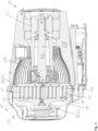
- ein Ausführungsbeispiel einer erfindungsgemäßen Scrollvakuumpumpe in einer Schnittansicht,
- Fig. 2
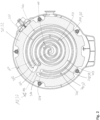
- eine Schnittansicht eines Pumpsystems einer erfindungsgemäßen Scrollvakuumpumpe, und
- Fig. 3
- eine schematische Darstellung zur Erläuterung minimalen Abstände im Spiralteil und in zwei Kreisteilen.
- Fig. 1
- an embodiment of a scroll vacuum pump according to the invention in a sectional view,
- Fig. 2
- a sectional view of a pumping system of a scroll vacuum pump according to the invention, and
- Fig. 3
- a schematic representation to explain minimum distances in the spiral part and in two circular parts.
Die in
Am vorderen Ende eines Pumpengehäuses 28 der Scrollvakuumpumpe 10 befindet sich das Pumpsystem 20 mit dem feststehenden Spiralbauteil 30 und dem beweglichen Spiralbauteil 40. Das auch als Spiralgehäuse bezeichnete feststehende Spiralbauteil 30 ist auf das vordere Ende des Pumpengehäuses 28 stirnseitig aufgeschraubt und von einer ebenfalls am Pumpengehäuse 28 angebrachten Haube umgeben.At the front end of a
Das bewegliche Spiralbauteil 40 umfasst einen Orbiterträger 42, das feststehende Spiralbauteil 30 einen Statorträger 32. In der dargestellten Ausführungsform der erfindungsgemäßen Scrollvakuumpumpe 10 gehen vom Orbiterträger 42 eine Spiralwand 110, eine Kreiswand 210 sowie eine weitere Kreiswand 310 aus, die in entsprechende Nuten, insbesondere eine Spiralnut 120, eine Kreisnut 220 sowie eine weitere Kreisnut 320, eingreifen, die im Statorträger 32 angeordnet sind.The movable scroll component 40 comprises an orbiter carrier 42, the fixed scroll component 30 a stator carrier 32. In the illustrated embodiment of the
Dadurch werden ein radial mittiger Spiralteil 100 sowie zwei radial außen anschließende Kreisteile 200, 300 gebildet, siehe insbesondere
Zwischen den jeweiligen Wänden 110, 210, 310 und Wandungen 122, 124, 222, 224, 322, 324 der Nuten 120, 220, 320 (vgl.
Weiter können die Spiralwand 110, die Kreiswand 210 und/oder die weitere Kreiswand 310 eine Beschichtung 50 aufweisen, insbesondere auf der jeweiligen Innenseite 114, 214, 314 oder Außenseite 116, 216, 316 (vgl.
In
Die gezeigten Abstände 130, 132, 134, 136, 230, 232, 330, 332 sind für einen Zustand der Scrollvakuumpumpe 10 in einem thermisch kalten Zustand gezeigt. Mit anderen Worten, es sind die Werte, die am Anfang eines Kaltstarts der Scrollvakuumpumpe 10 vorliegen. Durch die beim Betrieb auftretende Erwärmung werden die jeweiligen Wände 110, 210, 310 nach radial außen versetzt, jeweils umso mehr je weiter sie von einem Zentrum entfernt sind.The
Abbildung A ist deutlich entnehmbar, dass im Spiralteil 100 der radial inneren minimale Abstand 130 am Einlassende 102 einen geringeren Wert aufweist wie der der radial innere minimale Abstand 134 am Auslassende 102. Beide Abstände 130, 134 sind zwischen einer Innenseite 114 der Spiralwand 110 und einer radial inneren Innenwandung 122 der Spiralnut 120 definiert. Umgekehrt nimmt gleichzeitig ein radial äußerer minimaler Abstand 132, 136, festgelegt zwischen einer Außenseite 116 der Spiralwand 110 und einer radial äußeren Außenwandung 124 der Spiralnut 120, vom Einlassende 102 hin zum Auslassende 104 ab. Beide Änderungen berücksichtigen, dass das Auslassende 104 des Spiralteils 100 bevorzugt mittig im Pumpsystem 20 angeordnet ist, und das Einlassende 102 entsprechend radial weiter außen (vgl.
Abbildungen B, C zeigen jeweils die Situation für die Kreisteile 200, 300. Im Gegensatz zum Spiralteil 100 (Abbildung A) befinden sich die Kreiswände 210, 310 im Wesentlichen auf einem konstanten Radius. Aus diesem Grund sind die Werte der minimalen inneren Abstände 230, 330, jeweils ermittelt analog zum Spiralteil 100 zwischen einer Innenseite 214, 314 der jeweiligen Kreiswand 210, 310 und einer radial inneren Innenwandung 222, 322 der jeweiligen Kreisnut 220, 320, am jeweiligen Einlassende 202, 302 und am jeweiligen Auslassende 204, 304 identisch. Gleiches gilt für die Werte der minimalen äußeren Abstände 232, 332. Auch diese sind, erneut analog zum Spiralteil, zwischen einer Außenseite 216, 316 der jeweiligen Kreiswand 210, 310 und einer radial äußeren Außenwandung 224, 324 der jeweiligen Kreisnut 220, 320 definiert.Figures B and C show the situation for the
Bevorzugt können der radial innere minimale Abstand 230 des radial innenliegenden Kreisteils 200 (vgl.
Insbesondere kann hierbei vorgesehen sein, dass der radial innere minimale Abstand 230 des radial innenliegenden Kreisteils 200 an dessen Auslassende 204 größer ist, als ein radial innerer minimaler Abstand 130 des Spiralteils 100.In particular, it can be provided that the radially inner
Um die radiale Position des weiteren Kreisteils 300 außerhalb des radial inneren Kreisteils 200 zu berücksichtigen, kann der radial äußere minimale Abstand 232 des Kreisteils 200 kleiner sein als der radial äußere minimale Abstand 332 des weiteren Kreisteils 300.In order to take into account the radial position of the further
Zusammenfassend sind die Werte der minimalen Abstände 130, 132, 134, 136, 230, 232, 330, 332 derart gewählt, dass sie eine relative Änderung bei Temperaturanstieg der jeweiligen Wände 110, 210, 310 kompensieren. Gleichzeitig sind sie nicht zu klein gewählt, um ein Anlaufen der Wände 110, 210, 310 in den entsprechenden Nuten 120, 220, 320 bei einem Kaltstart zu verhindern.In summary, the values of the
- 1010
- ScrollvakuumpumpeScroll vacuum pump
- 2020
- PumpsystemPump system
- 2222
- Antriebswelledrive shaft
- 2424
- ExzenterabschnittEccentric section
- 2626
- Antriebsmotordrive motor
- 2828
- PumpengehäusePump housing
- 3030
- feststehendes Spiralbauteilfixed spiral component
- 3232
- StatorträgerStator carrier
- 4040
- bewegliches Spiralbauteilmovable spiral component
- 4242
- OrbiterträgerOrbiter carrier
- 5050
- BeschichtungCoating
- 100100
- SpiralteilSpiral part
- 102102
- EinlassendeAdmitting
- 104104
- AuslassendeOmitting
- 110110
- SpiralwandSpiral wall
- 112112
- WandstärkeWall thickness
- 114114
- Innenseiteinside
- 116116
- Außenseiteoutside
- 120120
- Spiralnutspiral groove
- 122122
- Innenwandunginner wall
- 124124
- Außenwandungexterior wall
- 130130
- radial innerer minimaler Abstand (Einlassende)radial inner minimum distance (inlet end)
- 132132
- radial äußerer minimaler Abstand (Einlassenderadial outer minimum distance (inlet end
- 134134
- radial innerer minimaler Abstand (Auslassende)radial inner minimum distance (outlet end)
- 136136
- radial äußerer minimaler Abstand (Auslassende)radial outer minimum distance (outlet end)
- 200200
- Kreisteilpart of a circle
- 202202
- EinlassendeAdmitting
- 204204
- AuslassendeOmitting
- 210210
- Kreiswandcircular wall
- 212212
- WandstärkeWall thickness
- 214214
- Innenseiteinside
- 216216
- Außenseiteoutside
- 220220
- Kreisnutcircular groove
- 222222
- Innenwandunginner wall
- 224224
- Außenwandungexterior wall
- 230230
- radial innerer minimaler Abstandradial inner minimum distance
- 232232
- radial äußerer minimaler Abstandradial outer minimum distance
- 300300
- weiterer Kreisteilfurther part of the district
- 302302
- EinlassendeAdmitting
- 304304
- AuslassendeOmitting
- 310310
- weitere Kreiswandfurther circular wall
- 312312
- WandstärkeWall thickness
- 314314
- Innenseiteinside
- 316316
- Außenseiteoutside
- 320320
- weitere Kreisnutfurther circular groove
- 322322
- Innenwandunginner wall
- 324324
- Außenwandungexterior wall
- 330330
- radial innerer minimaler Abstandradial inner minimum distance
- 332332
- radial äußerer minimaler Abstandradial outer minimum distance
Claims (15)
wobei in einem thermisch kalten Zustand des Pumpsystems (20) ein minimaler radialer Abstand (130) zwischen der Innenseite (114) der Spiralwand (110) und der Innenwandung (122) der Spiralnut (120) am Einlassende (102) des Spiralteils (100) kleiner ist als ein minimaler radialer Abstand (230) zwischen der Innenseite (214) der Kreiswand (210) und der Innenwandung (222) der Kreisnut (220) am Auslassende (204) des Kreisteils (200).Scroll vacuum pump (10) according to claim 1,
wherein in a thermally cold state of the pumping system (20), a minimum radial distance (130) between the inner side (114) of the spiral wall (110) and the inner wall (122) of the spiral groove (120) at the inlet end (102) of the spiral part (100) is smaller than a minimum radial distance (230) between the inner side (214) of the circular wall (210) and the inner wall (222) of the circular groove (220) at the outlet end (204) of the circular part (200).
wobei in einem thermisch kalten Zustand des Pumpsystems (20) in dem weiteren Kreisteil (300) ein minimaler radialer Abstand (330) zwischen einer radialen Innenseite (314) der weiteren Kreiswand (310) und einer radial inneren Innenwandung (322) der weiteren Kreisnut (320) kleiner ist als ein minimaler radialer Abstand (332) zwischen einer radialen Außenseite (314) der weiteren Kreiswand (310) und einer radial äußeren Außenwandung (324) der weiteren Kreisnut (320).Scroll vacuum pump (10) according to claim 4 or 5,
wherein in a thermally cold state of the pump system (20) in the further circular part (300) a minimum radial distance (330) between a radial inner side (314) of the further circular wall (310) and a radially inner inner wall (322) of the further circular groove (320) is smaller than a minimum radial distance (332) between a radial outer side (314) of the further circular wall (310) and a radially outer outer wall (324) of the further circular groove (320).
wobei in einem thermisch kalten Zustand des Pumpsystems (20) der minimale radiale Abstand (232) zwischen der Außenseite (214) der Kreiswand (210) und der Außenwandung (224) der Kreisnut (220) kleiner ist als der minimale radiale Abstand (332) zwischen der Außenseite (314) der weiteren Kreiswand (310) und der Außenwandung (324) der weiteren Kreisnut (320).Scroll vacuum pump (10) according to claim 8,
wherein in a thermally cold state of the pump system (20), the minimum radial distance (232) between the outer side (214) of the circular wall (210) and the outer wall (224) of the circular groove (220) is smaller than the minimum radial distance (332) between the outer side (314) of the further circular wall (310) and the outer wall (324) of the further circular groove (320).
wobei eine Dicke der Beschichtung (50) entlang einer umlaufenden Erstreckung der Spiralwand (110) und/oder der Kreiswand (210) und/oder der weiteren Kreiswand (310) konstant ist.Scroll vacuum pump (10) according to claim 13,
wherein a thickness of the coating (50) is constant along a circumferential extension of the spiral wall (110) and/or the circular wall (210) and/or the further circular wall (310).
wobei eine Dicke der Beschichtung (50) entlang einer umlaufenden Erstreckung der Spiralwand (110) und/oder der Kreiswand (210) und/oder der weiteren Kreiswand (310) variabel ist.Scroll vacuum pump (10) according to claim 13 or 14,
wherein a thickness of the coating (50) is variable along a circumferential extension of the spiral wall (110) and/or the circular wall (210) and/or the further circular wall (310).
Priority Applications (1)
| Application Number | Priority Date | Filing Date | Title |
|---|---|---|---|
| EP25160041.7A EP4538532A3 (en) | 2025-02-25 | 2025-02-25 | Scroll vacuum pump |
Applications Claiming Priority (1)
| Application Number | Priority Date | Filing Date | Title |
|---|---|---|---|
| EP25160041.7A EP4538532A3 (en) | 2025-02-25 | 2025-02-25 | Scroll vacuum pump |
Publications (2)
| Publication Number | Publication Date |
|---|---|
| EP4538532A2 true EP4538532A2 (en) | 2025-04-16 |
| EP4538532A3 EP4538532A3 (en) | 2025-08-27 |
Family
ID=94817609
Family Applications (1)
| Application Number | Title | Priority Date | Filing Date |
|---|---|---|---|
| EP25160041.7A Pending EP4538532A3 (en) | 2025-02-25 | 2025-02-25 | Scroll vacuum pump |
Country Status (1)
| Country | Link |
|---|---|
| EP (1) | EP4538532A3 (en) |
Citations (3)
| Publication number | Priority date | Publication date | Assignee | Title |
|---|---|---|---|---|
| EP3153708A1 (en) | 2015-10-06 | 2017-04-12 | Pfeiffer Vacuum Gmbh | Scroll pump and method for operating a scroll pump |
| EP3617511A2 (en) | 2019-10-07 | 2020-03-04 | Pfeiffer Vacuum Gmbh | Scroll pump and method of manufacturing same |
| EP3647599A2 (en) | 2019-10-07 | 2020-05-06 | Pfeiffer Vacuum Gmbh | Vacuum pump, scroll pump and method of manufacturing same |
Family Cites Families (4)
| Publication number | Priority date | Publication date | Assignee | Title |
|---|---|---|---|---|
| GB0304285D0 (en) * | 2003-02-25 | 2003-04-02 | Boc Group Plc | Scroll compressor |
| US7179067B2 (en) * | 2004-01-13 | 2007-02-20 | Scroll Technologies | Scroll compressor with wrap walls provided with an abradable coating and a load-bearing surface at radially outer locations |
| JP6226002B2 (en) * | 2016-01-26 | 2017-11-08 | ダイキン工業株式会社 | Scroll compressor and air conditioner equipped with the same |
| EP4506537B1 (en) * | 2023-08-08 | 2025-10-08 | Pfeiffer Vacuum Technology AG | Scroll vacuum pump |
-
2025
- 2025-02-25 EP EP25160041.7A patent/EP4538532A3/en active Pending
Patent Citations (3)
| Publication number | Priority date | Publication date | Assignee | Title |
|---|---|---|---|---|
| EP3153708A1 (en) | 2015-10-06 | 2017-04-12 | Pfeiffer Vacuum Gmbh | Scroll pump and method for operating a scroll pump |
| EP3617511A2 (en) | 2019-10-07 | 2020-03-04 | Pfeiffer Vacuum Gmbh | Scroll pump and method of manufacturing same |
| EP3647599A2 (en) | 2019-10-07 | 2020-05-06 | Pfeiffer Vacuum Gmbh | Vacuum pump, scroll pump and method of manufacturing same |
Also Published As
| Publication number | Publication date |
|---|---|
| EP4538532A3 (en) | 2025-08-27 |
Similar Documents
| Publication | Publication Date | Title |
|---|---|---|
| DE4227332C2 (en) | Screw compressor | |
| EP0295480B1 (en) | Positive displacement machine | |
| DE69123898T2 (en) | Rotary system for liquid media | |
| DE2939945C2 (en) | ||
| DE2529331C2 (en) | Screw compressor | |
| DE3015628A1 (en) | PRESSURE BEARING / COUPLING DEVICE AND AUQUIDED MACHINE | |
| DE2801206A1 (en) | SPIRAL DEVICE WITH A FIXED CRANE DRIVE MECHANISM | |
| DE69202399T2 (en) | Flow machine in spiral construction. | |
| DE7625941U1 (en) | ROTOR DISPENSER MACHINE WITH A SCREW | |
| DE1553238B2 (en) | Rotary piston machine | |
| DE3312280C2 (en) | ||
| DE69205900T2 (en) | Displacement machine based on the spiral principle. | |
| DE3911020A1 (en) | LUBRICATION-FREE ROTATIONAL PISTON MACHINE IN SCREW DESIGN | |
| WO2016016185A1 (en) | Valve for a fluid circuit of a motor vehicle | |
| WO2024132263A1 (en) | Positive-displacement machine | |
| EP4538532A2 (en) | Scroll vacuum pump | |
| EP0906512B1 (en) | Vane pump | |
| DE69424803T2 (en) | DISPLACEMENT MACHINE ACCORDING TO THE SPIRAL PRINCIPLE | |
| DE69001910T2 (en) | Fluid compressor. | |
| DE3139561C2 (en) | ||
| EP3158198B1 (en) | Liquid ring machine | |
| DE4134965A1 (en) | SPIRAL COMPRESSOR WITH MODIFIED HEAD | |
| WO2007039405A1 (en) | Vane pump | |
| DE69835520T2 (en) | SCREW COMPRESSORS WITH ADJUSTABLE FULL LOAD CAPACITY | |
| DE102020103384B4 (en) | Screw compressor with rotors supported on one side |
Legal Events
| Date | Code | Title | Description |
|---|---|---|---|
| PUAI | Public reference made under article 153(3) epc to a published international application that has entered the european phase |
Free format text: ORIGINAL CODE: 0009012 |
|
| STAA | Information on the status of an ep patent application or granted ep patent |
Free format text: STATUS: THE APPLICATION HAS BEEN PUBLISHED |
|
| AK | Designated contracting states |
Kind code of ref document: A2 Designated state(s): AL AT BE BG CH CY CZ DE DK EE ES FI FR GB GR HR HU IE IS IT LI LT LU LV MC ME MK MT NL NO PL PT RO RS SE SI SK SM TR |
|
| PUAL | Search report despatched |
Free format text: ORIGINAL CODE: 0009013 |
|
| AK | Designated contracting states |
Kind code of ref document: A3 Designated state(s): AL AT BE BG CH CY CZ DE DK EE ES FI FR GB GR HR HU IE IS IT LI LT LU LV MC ME MK MT NL NO PL PT RO RS SE SI SK SM TR |
|
| RIC1 | Information provided on ipc code assigned before grant |
Ipc: F04C 18/02 20060101AFI20250722BHEP Ipc: F04C 23/00 20060101ALI20250722BHEP Ipc: F04C 25/02 20060101ALI20250722BHEP Ipc: F04C 28/06 20060101ALI20250722BHEP |
|
| STAA | Information on the status of an ep patent application or granted ep patent |
Free format text: STATUS: REQUEST FOR EXAMINATION WAS MADE |
|
| 17P | Request for examination filed |
Effective date: 20260224 |
|
| STAA | Information on the status of an ep patent application or granted ep patent |
Free format text: STATUS: EXAMINATION IS IN PROGRESS |