EP4545871A1 - Amortisseur de bruit d'une conduite de ventilation - Google Patents
Amortisseur de bruit d'une conduite de ventilation Download PDFInfo
- Publication number
- EP4545871A1 EP4545871A1 EP24209008.2A EP24209008A EP4545871A1 EP 4545871 A1 EP4545871 A1 EP 4545871A1 EP 24209008 A EP24209008 A EP 24209008A EP 4545871 A1 EP4545871 A1 EP 4545871A1
- Authority
- EP
- European Patent Office
- Prior art keywords
- noise damper
- nozzle
- section
- air duct
- panels
- Prior art date
- Legal status (The legal status is an assumption and is not a legal conclusion. Google has not performed a legal analysis and makes no representation as to the accuracy of the status listed.)
- Pending
Links
Images


Classifications
-
- F—MECHANICAL ENGINEERING; LIGHTING; HEATING; WEAPONS; BLASTING
- F24—HEATING; RANGES; VENTILATING
- F24F—AIR-CONDITIONING; AIR-HUMIDIFICATION; VENTILATION; USE OF AIR CURRENTS FOR SCREENING
- F24F13/00—Details common to, or for air-conditioning, air-humidification, ventilation or use of air currents for screening
- F24F13/24—Means for preventing or suppressing noise
-
- F—MECHANICAL ENGINEERING; LIGHTING; HEATING; WEAPONS; BLASTING
- F16—ENGINEERING ELEMENTS AND UNITS; GENERAL MEASURES FOR PRODUCING AND MAINTAINING EFFECTIVE FUNCTIONING OF MACHINES OR INSTALLATIONS; THERMAL INSULATION IN GENERAL
- F16L—PIPES; JOINTS OR FITTINGS FOR PIPES; SUPPORTS FOR PIPES, CABLES OR PROTECTIVE TUBING; MEANS FOR THERMAL INSULATION IN GENERAL
- F16L55/00—Devices or appurtenances for use in, or in connection with, pipes or pipe systems
- F16L55/02—Energy absorbers; Noise absorbers
- F16L55/033—Noise absorbers
- F16L55/0336—Noise absorbers by means of sound-absorbing materials
-
- F—MECHANICAL ENGINEERING; LIGHTING; HEATING; WEAPONS; BLASTING
- F24—HEATING; RANGES; VENTILATING
- F24F—AIR-CONDITIONING; AIR-HUMIDIFICATION; VENTILATION; USE OF AIR CURRENTS FOR SCREENING
- F24F13/00—Details common to, or for air-conditioning, air-humidification, ventilation or use of air currents for screening
- F24F13/02—Ducting arrangements
- F24F13/0263—Insulation for air ducts
-
- F—MECHANICAL ENGINEERING; LIGHTING; HEATING; WEAPONS; BLASTING
- F24—HEATING; RANGES; VENTILATING
- F24F—AIR-CONDITIONING; AIR-HUMIDIFICATION; VENTILATION; USE OF AIR CURRENTS FOR SCREENING
- F24F13/00—Details common to, or for air-conditioning, air-humidification, ventilation or use of air currents for screening
- F24F13/24—Means for preventing or suppressing noise
- F24F2013/242—Sound-absorbing material
Definitions
- the invention falls within the field of ventilation systems and relates to a noise damper of a ventilation duct.
- a noise damper of a ventilation duct is known from the European patent application EP1580494 (published 28 September 2005 ).
- the noise damper has an internal air duct with a round cross-section, and the ends of the air duct have matching nozzles, or fittings, to connect the air duct of the noise damper to the ventilation pipes with a round cross-section.
- the nozzles between the air duct of the noise damper and the ventilation pipes are conical.
- a noise damper of a ventilation duct which has an internal air duct with a round cross-section, is known from the European patent application EP1998119 (published 3 December 2008 ).
- the ends of the air duct have nozzles to connect the air duct to the ventilation pipes with a round cross-section.
- the nozzles between the air duct and the ventilation pipes of the noise damper are implemented longitudinal as a smooth arch.
- the damping efficiency of the noise damper is significantly dependent on the narrowness of the air duct going through the noise damper.
- the narrower the air duct the closer the damping material on opposite sides of the air duct going through the noise damper is to each other, and the greater the damping efficiency.
- the air duct in the noise damper has a round cross-section, so reducing its diameter to increase the noise damping capacity will result in an increase in the aerodynamic drag of the noise damper. It is also more complex to manufacture a noise damper with a round cross-section air duct - special equipment is needed, which makes it expensive to manufacture.
- a prior solution most similar to the present invention is known from the Netherlands patent application NL7612377A (published 10 May 1978 ), which describes a noise damper of a ventilation duct comprising an outer shell and panels of sound-absorbing material therein, wherein an air duct with a rectangular cross-section is formed between the panels.
- the noise damper includes nozzles at the ends of the air duct to form a transition at each end of the air duct to connect an air duct with a rectangular cross-section to a ventilation pipe with a round cross-section.
- the nozzles, with the connecting parts at their ends are located outside the shell of the noise damper, i.e. noise can spread through the walls of the transition and these nozzles must therefore be isolated separately.
- the present invention provides a noise damper with an internal air duct with a rectangular cross-section, which is designed to be connected to ventilation pipes with a round cross-section.
- the two opposite sides of a duct of a noise damper with a rectangular or quadrangular cross-section can be brought relatively close to each other by selecting the cross-sectional proportions such that a cross-section is formed, where the duct is in one direction narrow and in other direction tall.
- the narrower the air duct the closer the panels of the damping material on opposite sides of the duct of the noise damper are to each other, and the greater the damping efficiency.
- the present invention proposes an aerodynamic nozzle, or fitting, for use within the noise damper to direct the airflow through the air duct of the noise damper from a low resistance round cross-section nozzle to an air duct (i.e., a dampening duct) with a rectangular cross-section and from there again out of the noise damper through the nozzle.
- the present invention proposes a noise damper of a ventilation duct, wherein the noise damper comprises an outer shell and panels of sound-absorbing material within said outer shell, wherein an air duct, or a damping duct, with a rectangular cross-section is formed between said panels.
- the noise damper comprises at each end of the air duct a nozzle forming at each end of the air duct a transition from a rectangular cross-section of the air duct to a round cross-section for connection to the ventilation pipe with a round cross-section.
- the nozzles are placed inside the noise damper so that the round cross-section connecting part at the round cross-section end of the nozzle extends through the end wall of the outer shell.
- the length of the nozzle between the rectangular cross-sectional end and the round cross-sectional end of the nozzle is 35% to 120% of the inner diameter of the round end of the nozzle.
- the longer side of the rectangular cross-section end of the nozzle is 70% to 120% of the inner diameter of the round end of the nozzle.
- the shorter side of the rectangular cross-section end of the nozzle is 25% to 60% of the inner diameter of the round end of the nozzle.
- the dimensions of the longer and shorter sides of the rectangular cross-sectioned end of the nozzle are measured from the inside of the aforementioned air duct.
- the nozzle is made of metal such as galvanized steel, plastic such as ABS, polyethylene, polypropylene, etc., composite material, moulded paper pulp or recycled materials.
- Panels of sound-absorbing material are preferably made of mineral wool, such as ISOVER TM mineral wool panels. Sound damping panels made of other materials, such as rock wool, glass wool, or recycled material, can also be used. PEPP (porous expanded polypropylene) panels, polyester-based damping panels, such as 100% polyester fibre panels, can also be used.
- the shell of the noise damper is preferably made of galvanized steel sheet.
- the noise damper 1 has the outer shell removed from around the panels 2, 3, 4 of sound-absorbing material and from one of the top panels 2 of sound-absorbing material (both panels 2 are shown on Figure 4 ).
- An air duct 5 and nozzles 6 at the ends 5 of the air duct are shown between the top panel 2 of sound-absorbing material and the two side panels 3 and 4 of sound-absorbing material.
- the round cross-sectioned end of the nozzle 6 is fitted with a round cross-sectioned connecting part 7, which is positioned through the end wall 8 of the outer shell and designed to connect the noise damper to the ventilation pipe.
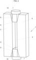
- Figure 2 shows the noise damper 1 according to Figure 1 without the outer shell, top panels 2 (see Figure 4 ) and end walls 8 - only the nozzles 6 and the panels 3 and 4 forming the wider sides of the air duct 5 are shown.
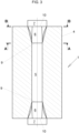
- Figure 3 shows a longitudinal section of the noise damper 1 - it can be seen that the ends of the lateral panels 3 and 4 of sound-absorbing material have cut-outs to accommodate the nozzles 6.
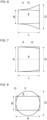
- Figures 4 and 5 show respectively sections A - A and B - B, the position of which is shown in Figure 3 .
- the noise damper 1 includes nozzles 6 at the ends of the air duct 5 to form aerodynamically smooth nozzles at each end of the air duct 5 from a rectangular cross-section of the air duct 5 to a round cross-section to connect to the ventilation pipe.
- the nozzles 6 are placed inside the noise damper 1 so that the round cross-section connecting part 7 at the round cross-section end of the nozzle 6 extends through the end wall 8 of the outer shell.
- Figures 6 to 11 The shape and configuration of the nozzle 6 is shown in Figures 6 to 11 , and in addition, Figures 12 to 14 show axonometric views of the frame model of the nozzle 6 to better represent its shape.
- Figures 4 and 5 show that the damping duct, or air duct 5, is formed between two panels 2 of sound-absorbing material and the side panels 3 and 4.
- the cross-section of the air duct 5 is a quadrangular, in this case rectangular, it can be easily formed between panels 2, 3, and 4 cut from flat blanks without the need to bend these panels.
- the nozzles 6 at the ends of the air duct 5 smoothly guide the air from one end of the noise damper 1 into the air duct 5 and smoothly out of the other end.
- the length L of the nozzle 6 between the rectangular cross-sectional end 9 and the round cross-sectional end 10 of the nozzle 6 is between 35% and 120% of the inner diameter D of the round end 10 of the nozzle 5.
- the longer side A of the rectangular cross-section end of the nozzle 6 is between 70% and 120% of the inner diameter D of the round end 10 of the nozzle 6.
- the shorter side B of the rectangular cross-section end of the nozzle 6 is between 25% and 60% of the inner diameter D of the round end 10 of nozzle 6.
Landscapes
- Engineering & Computer Science (AREA)
- General Engineering & Computer Science (AREA)
- Mechanical Engineering (AREA)
- Chemical & Material Sciences (AREA)
- Combustion & Propulsion (AREA)
- Duct Arrangements (AREA)
Applications Claiming Priority (1)
| Application Number | Priority Date | Filing Date | Title |
|---|---|---|---|
| EEU202300029U EE01639U1 (et) | 2023-10-27 | 2023-10-27 | Ventilatsioonikanali mürasummuti |
Publications (1)
| Publication Number | Publication Date |
|---|---|
| EP4545871A1 true EP4545871A1 (fr) | 2025-04-30 |
Family
ID=91899684
Family Applications (1)
| Application Number | Title | Priority Date | Filing Date |
|---|---|---|---|
| EP24209008.2A Pending EP4545871A1 (fr) | 2023-10-27 | 2024-10-25 | Amortisseur de bruit d'une conduite de ventilation |
Country Status (2)
| Country | Link |
|---|---|
| EP (1) | EP4545871A1 (fr) |
| EE (1) | EE01639U1 (fr) |
Families Citing this family (1)
| Publication number | Priority date | Publication date | Assignee | Title |
|---|---|---|---|---|
| CN119196923A (zh) * | 2024-08-27 | 2024-12-27 | 珠海格力电器股份有限公司 | 一种消音装置、噪音控制方法及空调器 |
Citations (6)
| Publication number | Priority date | Publication date | Assignee | Title |
|---|---|---|---|---|
| BE776812A (fr) * | 1970-12-17 | 1972-04-17 | Svenska Flaektfabriken Ab | Dispositif d'admission et d'evacuation d'air d'installations deventilation, reduisant la communication acoustique |
| NL7612377A (en) | 1976-11-08 | 1978-05-10 | Indola Electric Bv | Noise damper for a ventilating system - has housing filled with sound-absorbent polyurethane foam changing air duct section |
| EP1580494A1 (fr) * | 2004-03-24 | 2005-09-28 | Uponor Innovation Ab | Silencieux pour conduit de ventilation |
| EP1998119B1 (fr) * | 2007-05-31 | 2013-04-03 | Swegon AB | Silencieux pour conduites de ventilation |
| EP2894414A1 (fr) * | 2013-11-20 | 2015-07-15 | Atlantic Climatisation et Ventilation | Unite de ventilation à piege à son |
| CN113623478A (zh) * | 2021-08-27 | 2021-11-09 | 山东洁静环保设备有限公司 | 一种模块组装式消声器 |
Family Cites Families (2)
| Publication number | Priority date | Publication date | Assignee | Title |
|---|---|---|---|---|
| DE2521119A1 (de) * | 1975-05-13 | 1976-11-18 | Gruenzweig Hartmann Glasfaser | Schalldaempfer fuer rohrleitungen |
| SE543236C2 (en) * | 2018-03-02 | 2020-10-27 | Lindab Ab | A silencer for airflow in ventilation |
-
2023
- 2023-10-27 EE EEU202300029U patent/EE01639U1/et unknown
-
2024
- 2024-10-25 EP EP24209008.2A patent/EP4545871A1/fr active Pending
Patent Citations (6)
| Publication number | Priority date | Publication date | Assignee | Title |
|---|---|---|---|---|
| BE776812A (fr) * | 1970-12-17 | 1972-04-17 | Svenska Flaektfabriken Ab | Dispositif d'admission et d'evacuation d'air d'installations deventilation, reduisant la communication acoustique |
| NL7612377A (en) | 1976-11-08 | 1978-05-10 | Indola Electric Bv | Noise damper for a ventilating system - has housing filled with sound-absorbent polyurethane foam changing air duct section |
| EP1580494A1 (fr) * | 2004-03-24 | 2005-09-28 | Uponor Innovation Ab | Silencieux pour conduit de ventilation |
| EP1998119B1 (fr) * | 2007-05-31 | 2013-04-03 | Swegon AB | Silencieux pour conduites de ventilation |
| EP2894414A1 (fr) * | 2013-11-20 | 2015-07-15 | Atlantic Climatisation et Ventilation | Unite de ventilation à piege à son |
| CN113623478A (zh) * | 2021-08-27 | 2021-11-09 | 山东洁静环保设备有限公司 | 一种模块组装式消声器 |
Also Published As
| Publication number | Publication date |
|---|---|
| EE01639U1 (et) | 2024-07-15 |
Similar Documents
| Publication | Publication Date | Title |
|---|---|---|
| JP5012249B2 (ja) | 車両空調用吹出ダクトおよび車両用空調装置 | |
| EP4545871A1 (fr) | Amortisseur de bruit d'une conduite de ventilation | |
| JP5258776B2 (ja) | 航空機エアパイプライン、特に航空機空調システム用音波吸収装置 | |
| US5953818A (en) | Method of kerfing insulation boards and duct liners and the like formed from said boards | |
| EP1878008B1 (fr) | Dispositif a canal d'ecoulement d'attenuation sonore | |
| CN101338846A (zh) | 一种柔性消声器 | |
| JP3383798B2 (ja) | 気流吹出し装置 | |
| JP2020067266A (ja) | 空気吹出装置 | |
| KR20120008392U (ko) | 소음저감형 공조기 덕트 | |
| KR101719060B1 (ko) | 소음 저감형 덕트 | |
| US3643580A (en) | Fluid distribution apparatus preserving alignment of longitudinal axes of flow | |
| CN102261528A (zh) | 一种柔性金属扣合消声通风软管 | |
| DE102004019446B4 (de) | Geräuscharmes Saugrohr | |
| JP4657240B2 (ja) | 建物におけるエアダクトのベンチュリ型接続エアダクトの支持構造 | |
| CN206488659U (zh) | 中小型冷却塔消声器 | |
| CN203052007U (zh) | 空调系统用通风管、空调系统和车辆 | |
| CA2379170A1 (fr) | Rail pour aubes et son assemblage dans une gaine de circulation d'air | |
| CN220228220U (zh) | 用于防火阀连接的防火风管连接结构 | |
| CN218762068U (zh) | 一种气流输送装置的弯头风管 | |
| JP2006145117A (ja) | 空調用吹出口 | |
| JP2006057967A (ja) | 分岐型サプライチャンバー | |
| CN221482897U (zh) | 成品防火风管 | |
| AU721569B2 (en) | An air conditioning duct fitting | |
| WO2020204694A1 (fr) | Ensemble de conduit d'évacuation de fluide | |
| CN217357261U (zh) | 一种空调器及其出管板 |
Legal Events
| Date | Code | Title | Description |
|---|---|---|---|
| PUAI | Public reference made under article 153(3) epc to a published international application that has entered the european phase |
Free format text: ORIGINAL CODE: 0009012 |
|
| STAA | Information on the status of an ep patent application or granted ep patent |
Free format text: STATUS: THE APPLICATION HAS BEEN PUBLISHED |
|
| AK | Designated contracting states |
Kind code of ref document: A1 Designated state(s): AL AT BE BG CH CY CZ DE DK EE ES FI FR GB GR HR HU IE IS IT LI LT LU LV MC ME MK MT NL NO PL PT RO RS SE SI SK SM TR |
|
| STAA | Information on the status of an ep patent application or granted ep patent |
Free format text: STATUS: REQUEST FOR EXAMINATION WAS MADE |
|
| 17P | Request for examination filed |
Effective date: 20251016 |