EP4546586A1 - Gleichstrom-energiekabelsystem - Google Patents
Gleichstrom-energiekabelsystem Download PDFInfo
- Publication number
- EP4546586A1 EP4546586A1 EP23827509.3A EP23827509A EP4546586A1 EP 4546586 A1 EP4546586 A1 EP 4546586A1 EP 23827509 A EP23827509 A EP 23827509A EP 4546586 A1 EP4546586 A1 EP 4546586A1
- Authority
- EP
- European Patent Office
- Prior art keywords
- layer
- electrode
- direct
- electric field
- current power
- Prior art date
- Legal status (The legal status is an assumption and is not a legal conclusion. Google has not performed a legal analysis and makes no representation as to the accuracy of the status listed.)
- Pending
Links
Images


Classifications
-
- H—ELECTRICITY
- H01—ELECTRIC ELEMENTS
- H01R—ELECTRICALLY-CONDUCTIVE CONNECTIONS; STRUCTURAL ASSOCIATIONS OF A PLURALITY OF MUTUALLY-INSULATED ELECTRICAL CONNECTING ELEMENTS; COUPLING DEVICES; CURRENT COLLECTORS
- H01R4/00—Electrically-conductive connections between two or more conductive members in direct contact, i.e. touching one another; Means for effecting or maintaining such contact; Electrically-conductive connections having two or more spaced connecting locations for conductors and using contact members penetrating insulation
- H01R4/02—Soldered or welded connections
- H01R4/021—Soldered or welded connections between two or more cables or wires
-
- C—CHEMISTRY; METALLURGY
- C08—ORGANIC MACROMOLECULAR COMPOUNDS; THEIR PREPARATION OR CHEMICAL WORKING-UP; COMPOSITIONS BASED THEREON
- C08K—Use of inorganic or non-macromolecular organic substances as compounding ingredients
- C08K3/00—Use of inorganic substances as compounding ingredients
- C08K3/02—Elements
- C08K3/04—Carbon
-
- C—CHEMISTRY; METALLURGY
- C08—ORGANIC MACROMOLECULAR COMPOUNDS; THEIR PREPARATION OR CHEMICAL WORKING-UP; COMPOSITIONS BASED THEREON
- C08K—Use of inorganic or non-macromolecular organic substances as compounding ingredients
- C08K3/00—Use of inorganic substances as compounding ingredients
- C08K3/10—Metal compounds
- C08K3/14—Carbides
-
- C—CHEMISTRY; METALLURGY
- C08—ORGANIC MACROMOLECULAR COMPOUNDS; THEIR PREPARATION OR CHEMICAL WORKING-UP; COMPOSITIONS BASED THEREON
- C08K—Use of inorganic or non-macromolecular organic substances as compounding ingredients
- C08K3/00—Use of inorganic substances as compounding ingredients
- C08K3/18—Oxygen-containing compounds, e.g. metal carbonyls
- C08K3/20—Oxides; Hydroxides
- C08K3/22—Oxides; Hydroxides of metals
-
- C—CHEMISTRY; METALLURGY
- C08—ORGANIC MACROMOLECULAR COMPOUNDS; THEIR PREPARATION OR CHEMICAL WORKING-UP; COMPOSITIONS BASED THEREON
- C08L—COMPOSITIONS OF MACROMOLECULAR COMPOUNDS
- C08L23/00—Compositions of homopolymers or copolymers of unsaturated aliphatic hydrocarbons having only one carbon-to-carbon double bond; Compositions of derivatives of such polymers
- C08L23/02—Compositions of homopolymers or copolymers of unsaturated aliphatic hydrocarbons having only one carbon-to-carbon double bond; Compositions of derivatives of such polymers not modified by chemical after-treatment
- C08L23/16—Ethylene-propylene or ethylene-propylene-diene copolymers
-
- C—CHEMISTRY; METALLURGY
- C08—ORGANIC MACROMOLECULAR COMPOUNDS; THEIR PREPARATION OR CHEMICAL WORKING-UP; COMPOSITIONS BASED THEREON
- C08L—COMPOSITIONS OF MACROMOLECULAR COMPOUNDS
- C08L83/00—Compositions of macromolecular compounds obtained by reactions forming in the main chain of the macromolecule a linkage containing silicon with or without sulfur, nitrogen, oxygen or carbon only; Compositions of derivatives of such polymers
- C08L83/04—Polysiloxanes
-
- H—ELECTRICITY
- H01—ELECTRIC ELEMENTS
- H01B—CABLES; CONDUCTORS; INSULATORS; SELECTION OF MATERIALS FOR THEIR CONDUCTIVE, INSULATING OR DIELECTRIC PROPERTIES
- H01B3/00—Insulators or insulating bodies characterised by the insulating materials; Selection of materials for their insulating or dielectric properties
- H01B3/18—Insulators or insulating bodies characterised by the insulating materials; Selection of materials for their insulating or dielectric properties mainly consisting of organic substances
- H01B3/30—Insulators or insulating bodies characterised by the insulating materials; Selection of materials for their insulating or dielectric properties mainly consisting of organic substances plastics; resins; waxes
-
- H—ELECTRICITY
- H01—ELECTRIC ELEMENTS
- H01B—CABLES; CONDUCTORS; INSULATORS; SELECTION OF MATERIALS FOR THEIR CONDUCTIVE, INSULATING OR DIELECTRIC PROPERTIES
- H01B7/00—Insulated conductors or cables characterised by their form
- H01B7/14—Submarine cables
-
- H—ELECTRICITY
- H01—ELECTRIC ELEMENTS
- H01B—CABLES; CONDUCTORS; INSULATORS; SELECTION OF MATERIALS FOR THEIR CONDUCTIVE, INSULATING OR DIELECTRIC PROPERTIES
- H01B9/00—Power cables
-
- H—ELECTRICITY
- H02—GENERATION; CONVERSION OR DISTRIBUTION OF ELECTRIC POWER
- H02G—INSTALLATION OF ELECTRIC CABLES OR LINES, OR OF COMBINED OPTICAL AND ELECTRIC CABLES OR LINES
- H02G15/00—Cable fittings
- H02G15/08—Cable junctions
- H02G15/10—Cable junctions protected by boxes, e.g. by distribution, connection or junction boxes
- H02G15/103—Cable junctions protected by boxes, e.g. by distribution, connection or junction boxes with devices for relieving electrical stress
-
- H—ELECTRICITY
- H02—GENERATION; CONVERSION OR DISTRIBUTION OF ELECTRIC POWER
- H02G—INSTALLATION OF ELECTRIC CABLES OR LINES, OR OF COMBINED OPTICAL AND ELECTRIC CABLES OR LINES
- H02G15/00—Cable fittings
- H02G15/08—Cable junctions
- H02G15/18—Cable junctions protected by sleeves, e.g. for communication cable
- H02G15/184—Cable junctions protected by sleeves, e.g. for communication cable with devices for relieving electrical stress
-
- C—CHEMISTRY; METALLURGY
- C08—ORGANIC MACROMOLECULAR COMPOUNDS; THEIR PREPARATION OR CHEMICAL WORKING-UP; COMPOSITIONS BASED THEREON
- C08K—Use of inorganic or non-macromolecular organic substances as compounding ingredients
- C08K3/00—Use of inorganic substances as compounding ingredients
- C08K3/18—Oxygen-containing compounds, e.g. metal carbonyls
- C08K3/20—Oxides; Hydroxides
- C08K3/22—Oxides; Hydroxides of metals
- C08K2003/2296—Oxides; Hydroxides of metals of zinc
-
- H—ELECTRICITY
- H01—ELECTRIC ELEMENTS
- H01R—ELECTRICALLY-CONDUCTIVE CONNECTIONS; STRUCTURAL ASSOCIATIONS OF A PLURALITY OF MUTUALLY-INSULATED ELECTRICAL CONNECTING ELEMENTS; COUPLING DEVICES; CURRENT COLLECTORS
- H01R4/00—Electrically-conductive connections between two or more conductive members in direct contact, i.e. touching one another; Means for effecting or maintaining such contact; Electrically-conductive connections having two or more spaced connecting locations for conductors and using contact members penetrating insulation
- H01R4/02—Soldered or welded connections
- H01R4/029—Welded connections
-
- H—ELECTRICITY
- H01—ELECTRIC ELEMENTS
- H01R—ELECTRICALLY-CONDUCTIVE CONNECTIONS; STRUCTURAL ASSOCIATIONS OF A PLURALITY OF MUTUALLY-INSULATED ELECTRICAL CONNECTING ELEMENTS; COUPLING DEVICES; CURRENT COLLECTORS
- H01R4/00—Electrically-conductive connections between two or more conductive members in direct contact, i.e. touching one another; Means for effecting or maintaining such contact; Electrically-conductive connections having two or more spaced connecting locations for conductors and using contact members penetrating insulation
- H01R4/10—Electrically-conductive connections between two or more conductive members in direct contact, i.e. touching one another; Means for effecting or maintaining such contact; Electrically-conductive connections having two or more spaced connecting locations for conductors and using contact members penetrating insulation effected solely by twisting, wrapping, bending, crimping, or other permanent deformation
- H01R4/18—Electrically-conductive connections between two or more conductive members in direct contact, i.e. touching one another; Means for effecting or maintaining such contact; Electrically-conductive connections having two or more spaced connecting locations for conductors and using contact members penetrating insulation effected solely by twisting, wrapping, bending, crimping, or other permanent deformation by crimping
- H01R4/187—Electrically-conductive connections between two or more conductive members in direct contact, i.e. touching one another; Means for effecting or maintaining such contact; Electrically-conductive connections having two or more spaced connecting locations for conductors and using contact members penetrating insulation effected solely by twisting, wrapping, bending, crimping, or other permanent deformation by crimping combined with soldering or welding
-
- H—ELECTRICITY
- H01—ELECTRIC ELEMENTS
- H01R—ELECTRICALLY-CONDUCTIVE CONNECTIONS; STRUCTURAL ASSOCIATIONS OF A PLURALITY OF MUTUALLY-INSULATED ELECTRICAL CONNECTING ELEMENTS; COUPLING DEVICES; CURRENT COLLECTORS
- H01R4/00—Electrically-conductive connections between two or more conductive members in direct contact, i.e. touching one another; Means for effecting or maintaining such contact; Electrically-conductive connections having two or more spaced connecting locations for conductors and using contact members penetrating insulation
- H01R4/10—Electrically-conductive connections between two or more conductive members in direct contact, i.e. touching one another; Means for effecting or maintaining such contact; Electrically-conductive connections having two or more spaced connecting locations for conductors and using contact members penetrating insulation effected solely by twisting, wrapping, bending, crimping, or other permanent deformation
- H01R4/18—Electrically-conductive connections between two or more conductive members in direct contact, i.e. touching one another; Means for effecting or maintaining such contact; Electrically-conductive connections having two or more spaced connecting locations for conductors and using contact members penetrating insulation effected solely by twisting, wrapping, bending, crimping, or other permanent deformation by crimping
- H01R4/20—Electrically-conductive connections between two or more conductive members in direct contact, i.e. touching one another; Means for effecting or maintaining such contact; Electrically-conductive connections having two or more spaced connecting locations for conductors and using contact members penetrating insulation effected solely by twisting, wrapping, bending, crimping, or other permanent deformation by crimping using a crimping sleeve
-
- H—ELECTRICITY
- H01—ELECTRIC ELEMENTS
- H01R—ELECTRICALLY-CONDUCTIVE CONNECTIONS; STRUCTURAL ASSOCIATIONS OF A PLURALITY OF MUTUALLY-INSULATED ELECTRICAL CONNECTING ELEMENTS; COUPLING DEVICES; CURRENT COLLECTORS
- H01R4/00—Electrically-conductive connections between two or more conductive members in direct contact, i.e. touching one another; Means for effecting or maintaining such contact; Electrically-conductive connections having two or more spaced connecting locations for conductors and using contact members penetrating insulation
- H01R4/70—Insulation of connections
Definitions
- the present invention relates to a direct-current power cable system. More specifically, the present invention relates to a direct-current power cable system capable of alleviating an electric field in a portion where space charges excessively accumulate inside a sleeve member of an ultra-high voltage direct-current power cable system, thereby preventing or minimizing electric field distortion and insulation breakdown of a cable joint box due to local electric field concentration.
- Transmission methods may be broadly divided into alternating-current transmission and direct-current transmission, among which direct-current transmission refers to the transmission of power using a direct-current method.
- direct-current transmission first converts alternating-current power on a transmission side to an appropriate voltage, then transforms it into direct current through a forward conversion device, and transmits it to the receiving side via a transmission line.
- a reverse conversion device then converts the direct-current power back into alternating-current power.
- the direct-current transmission offers advantages in transporting large-capacity power over long distances and enables interconnection of asynchronous power systems. Additionally, in long-distance transmission, direct current offers advantages in having lower power loss and higher stability compared to alternating current.
- HVDC cable The ultra-high voltage direct-current power cables used in the direct-current power transmission, known as the high voltage direct-current cable (HVDC cable), are installed and interconnected by units of several tens to hundreds of meters through a cable joint box.
- HVDC cable high voltage direct-current cable
- FIG. 9 illustrates an example of a direct-current power cable system according to conventional technology.
- a general direct-current power cable system may be configured to include a first electrode 310' disposed on a conductor connection portion of a pair of direct-current power cables, a pair of second electrodes 320' disposed facing each other, an electric field alleviation layer 330' connected to the first electrode 310' and the pair of second electrodes 320' and configured with a dedicated rubber insulating material, a rubber insulating layer 340' provided to surround the electric field alleviation layer 330', and a sleeve member 300' provided with a sleeve shielding layer 350' disposed to surround the rubber insulating layer.
- the electric field alleviation layer 330' is configured from a thermosetting rubber resin containing a filler material that induces nonlinear electrical behavior according to a specific electric field. Under normal operating conditions, the electric field alleviation layer 330' operates as an insulating layer with sufficiently high resistance; however, when space charges accumulate and an excessive electric field form, the resistance of the electric field alleviation layer 330' nonlinearly decreases, allowing charges to dissipate along the electric field alleviation layer 330' toward the second electrode 320' and an outer semiconductive layer 16. This process relieves the accumulation of space charges, thereby preventing insulation breakdown caused by electric field concentration.
- electric field alleviation layer is absent in the power cable system illustrated in FIG. 9 , electric field concentration intensifies at the heterogeneous interface between an insulating layer 16' of the power cable and the rubber insulating layer 340'. Additionally, a triple point is formed at a region where the insulating layer 16' of the power cable, the rubber insulating layer 340' of the sleeve member, and the second electrode 320' meet, thereby increasing the possibility of insulation breakdown.
- a heterogeneous interface is not formed between the insulating layer 16' of the power cable and the rubber insulating layer 340' of the sleeve member.
- a heterogeneous interface still exists between the insulating layer 16' of the power cable and the electric field alleviation layer 330' of the sleeve member or between the electric field alleviation layer 330' and the rubber insulating layer 340' of the sleeve member 300.
- a triple point is formed at the region where the electric field alleviation layer 330', the rubber insulating layer 340', and the second electrode 320' of the sleeve member 300 meet, existing a potential for insulation breakdown.
- the manufacturing process of the electric field alleviation layer 330' is relatively complex, and the filler contained in the electric field alleviation layer 330' is costly. Consequently, when the size of the electric field alleviation layer 330' within the sleeve member 300' is expanded, the manufacturing process becomes more challenging, and the cost of the cable joint box increases.
- a direct-current power cable system may alleviate electric field concentration in portions of the sleeve member of an ultra-high voltage direct-current power cable where space charges excessively accumulate, thereby preventing or minimizing electric field distortion and reduction in direct-current dielectric strength due to space charge accumulation.
- the present invention is directed to providing a direct-current power cable system that alleviates electric field concentration in portions of the sleeve member of an ultra-high voltage direct-current power cable system where space charges excessively accumulate, thereby preventing or minimizing electric field distortion and reduction in direct-current dielectric strength due to space charge accumulation.
- the present invention is directed to providing a direct-current power cable system, comprising: a pair of direct-current power cables, each including a conductor, an inner semiconductive layer surrounding the conductor, an insulating layer surrounding the inner semiconductive layer, and an outer semiconductive layer surrounding the insulating layer, wherein cable connection regions in which the conductor, the insulating layer, and the outer semiconductive layer are sequentially exposed are disposed to face each other; a cable joint box connecting the pair of direct-current power cables, the cable joint box including: a conductor connection portion configured to connect the conductors of the pair of direct-current power cables; a sleeve member mounted to surround the conductor connection portion and the cable connection regions; and a housing accommodating the sleeve member, in which the sleeve member may include: a first electrode disposed to surround the conductor connection portion and electrically connected to the conductor connection portion; a pair of second electrodes each provided on both sides of the first electrode along a cable length direction; an electric field
- the sleeve shielding layer may be provided to be separated from the second electrode, and a distance between both ends of the sleeve shielding layer may be formed shorter than a distance between both ends of the rubber insulating layer so that a path for a creepage distance from the sleeve shielding layer to the second electrode is formed in a stepped shape.
- the distance between both ends of the rubber insulating layer may be formed shorter than a distance between both ends of the electric field alleviation layer, so that the path of the creepage distance from the sleeve shielding layer to the second electrode is formed in a stepped shape.
- the electric field alleviation layer may be configured from a material with higher electrical conductivity than the rubber insulating layer.
- the conductor connection portion may include a conductor sleeve configured to connect the conductors of the pair of direct-current power cables, and a corona shield mounted on an outer side of the conductor sleeve and electrically connected to the conductor sleeve.
- the electric field alleviation layer may be provided to surround an entire region of an outer circumferential surface of the first electrode disposed in the center portion, and provided with an outer diameter variation section where an outer diameter of the electric field alleviation layer changes between the first electrode and the second electrode.
- the electric field alleviation layer may include: a first electrode covering portion surrounding the first electrode; a pair of connection portions extending in a direction from both sides of the first electrode covering portion toward the second electrode, with a reduced outer diameter compared to the first electrode covering portion; a pair of inclined portions connected to the connection portions, with an increasing outer diameter in a direction of the second electrode to have an inclined section; and a pair of second electrode covering portions connected to the inclined portions, surrounding at least a portion of the second electrode, in which at least of a portion of the pair of second electrode covering portions may be disposed between the second electrode and the outer semiconductive layer so that the second electrode and the outer semiconductive layer are in a non-contact state, and in contact with the outer semiconductive layer.
- the second electrode covering portion may include a second electrode lower side cover portion disposed between the outer semiconductive layer and the second electrode, and a second electrode upper side cover portion surrounding at least a portion of an upper side of the second electrode.
- electrical conductivity of the rubber insulating layer may be 10 -12 to 10 -15 S/m (Siemens per meter), and electrical conductivity of the electric field alleviation layer may be 5 to 10,000 times greater than electrical conductivity of the rubber insulating layer.
- a slope of the inclined portion of the electric field alleviation layer may be in the range of 5 degrees to 45 degrees.
- the electric field alleviation layer may be configured from an insulating composition including a thermosetting rubber and a filler that induces nonlinear electrical behavior.
- thermosetting rubber may be liquid silicone rubber (LSR) or ethylene propylene rubber (EPDM).
- LSR liquid silicone rubber
- EPDM ethylene propylene rubber
- the filler may include silicon carbide.
- the housing may have a waterproofing material filled therein.
- the cable joint box may be a normal joint that electrically connects both ends of the sleeve shielding layer to the pair of second electrodes on both sides using electrical connection means.
- the cable joint box may be an insulation joint that electrically connects one end of the sleeve shielding layer to only one of the second electrodes using electrical connection means, while the other end of the sleeve shielding layer and a remaining second electrode are in an insulated state.
- the housing may be made of a metal material.
- the electric field alleviation layer configuring the sleeve member is provided between the second electrode and the outer semiconductive layer of the power cable.
- the contact area between the electric field alleviation layer and the second electrode increases, and the electric field alleviation layer is in direct contact with the outer semiconductive layer, further increasing the contact area.
- the structure in which the electric field alleviation layer of the sleeve member surrounds the second electrode is applied. This prevents the formation of a triple point where the second electrode, rubber insulating layer, and electric field alleviation layer of the sleeve member meet at a single point, thereby exhibiting an effect of effectively preventing excessive accumulation phenomenon of space charges within the sleeve member.
- the electric field alleviation layer configuring the sleeve member is provided to surround the entire region of the first electrode and at least a portion of the pair of second electrodes.
- This configuration forms a microcurrent path within the electric field alleviation layer, allowing charges to move from the first electrode toward the pair of second electrodes, thereby exhibiting an effect of alleviating the electric field at the edge end region of the first electrode.
- configuring the thickness or outer diameter of each section of the electric field alleviation layer in the lengthwise direction of the sleeve member differently has an effect of preventing the phenomenon of dielectric strength reduction caused by the electric field alleviation layer becoming excessively large, while also minimizing costs.
- the pair of second electrodes configuring the sleeve member are configured to be separated from the sleeve shielding layer to prevent contact.
- the path of the creepage distance from the sleeve shielding layer to the second electrode is formed in a stepped shape, with the distance between both ends of the sleeve shielding layer made shorter than the distance between both ends of the rubber insulating layer. This configuration secures the creepage distance between the sleeve shielding layer and the second electrode, thereby enabling diagnostic tasks, such as partial discharge signal diagnosis or fault diagnosis, of the direct-current power cable system.
- FIG. 1 illustrates an embodiment of an underground power cable applied to a direct-current power cable system according to the present invention.
- a power cable 100 is provided with a conductor 10 at a center thereof.
- the conductor 10 serves as a passage for current flow and may, for example, be configured from materials such as copper or aluminum.
- the conductor 10 illustrated in FIG. 1 is illustrated as being configured by stranding multiple wires 11, but is not limited thereto, the conductor may also be configured in various forms, such as a flat conductor.
- the conductor 10 configured by stranding wires or similar elements may have an uneven surface, leading to an uneven electric field and making partial corona discharge more likely.
- the insulation performance may be degraded when voids are formed between the surface of the conductor 10 and an insulation layer 14 described below.
- an inner semiconductive layer 12 configured from a semiconductive material may be provided on an outer side of the conductor 10.
- the insulating layer 14 is provided on an outer side of the inner semiconductive layer 12.
- the insulating layer 14 electrically insulates the conductor 10 from the outside.
- the insulating layer 14 needs to have a high breakdown voltage and maintain stable insulation performance over an extended period. Further, the insulating layer 14 exhibit low dielectric loss and possess thermal resistance performance, such as heat resistance. Accordingly, the insulating layer 14 uses polyolefin resins such as polyethylene and polypropylene, with polyethylene resin being preferred.
- the polyethylene resin may be a crosslinked resin and may be manufactured using a crosslinking agent such as silane or an organic peroxide, for example, dicumyl peroxide (DCP), etc.
- the insulating layer 14 may include inorganic particles in addition to the crosslinked resin.
- the inorganic particles may include nano-sized aluminosilicate, calcium silicate, calcium carbonate, magnesium oxide, and similar materials.
- magnesium oxide is the preferred inorganic particle.
- the magnesium oxide may be obtained from natural magnesium ores, but it may also be produced from artificial synthetic sources using magnesium salts in seawater, with the additional advantage of being supplied as a high-purity material with stable quality and properties.
- the magnesium oxide basically has the crystal structure of a face-centered cubic structure, but may have various shapes, purities, degrees of crystallinity, and physical properties depending on the synthesis method. Specifically, the magnesium oxide is classified into cubic, terrace, rod, porous, and spherical types and may be used in various applications according to each unique physical property.
- the inorganic particles, including such magnesium oxide, exert an effect of suppressing the movement of charges and the accumulation of space charges by forming a potential well at the interface between the base resin and the inorganic particles when an electric field is applied to the cable.
- the inorganic particles added to the insulating layer 14 may act as impurities when added in large amounts, and even in small amounts, the inorganic particles present the problem of reducing impulse strength, which is another critical property required in power cables. Therefore, it is preferable to add the inorganic particles in an amount of 0.2 to 5 parts by weight, as inorganic particles alone cannot sufficiently reduce accumulated space charges.
- the outer semiconductive layer 16 is provided on an outer side of the insulating layer 14.
- the outer semiconductive layer 16 serves to create an equipotential distribution of electric field lines between the aforementioned inner semiconductive layer 12, thereby enhancing the dielectric strength of the insulating layer 14.
- the outer semiconductive layer 16 smooths the surface of the insulating layer 14 in the cable, alleviating electric field concentration and thereby preventing corona discharge.
- a shielding layer 18 consisting of either a metal sheath or a neutral wire depending on the type of cable.
- the shielding layer 18 is provided for electrical shielding and as a return path for short-circuit currents.
- a cable jacket 20 is provided on an outermost portion of the power cable 100.
- the cable jacket 20 is provided on an outer circumference of the cable 100 and serves to protect the internal configuration of the cable 100. Accordingly, the cable jacket 20 is endowed with excellent weather resistance to endure various climatic and natural environmental factors, such as light, wind, rain, moisture, and atmospheric gases, as well as chemical resistance to withstand exposure to chemicals, along with high mechanical strength.
- the cable jacket is manufactured with materials such as polyvinyl chloride (PVC) or polyethylene (PE).
- FIG. 2 illustrates an embodiment of a submarine cable 100' applied to the direct-current power cable system according to the present invention. The differences will be described in comparison to the previously described embodiment in FIG. 1 .
- the conductor 10 the inner semiconductive layer 12, the insulating layer 14, and the outer semiconductive layer 16 are similar to the embodiment described in FIG. 1 , and therefore, repetitive descriptions are omitted.
- a sheath 32 configured from a resin such as polyethylene is provided with a bedding layer 34 to prevent direct contact with water.
- Sheathing wires 40 may be provided on the bedding layer 34.
- the sheathing wires 40 are provided on the outer circumference of the cable to serve to enhance mechanical strength in order to protect the cable from the external environment of the seabed.
- a serving layer 42 is provided as the outer covering of the cable.
- the serving layer 42 is provided on the outer circumference of the cable and serves to protect the internal configuration of the cable.
- the serving layer 42 possesses excellent weather resistance and mechanical strength to withstand submarine environments, such as exposure to seawater.
- the serving layer 42 may be configured from materials such as polypropylene yarn.
- Each direct-current power cable described with reference to FIGS. 1 and 2 has a matching core structure, aside from the cable protective layer structure according to the installation environment. Accordingly, hereinafter, a description will be provided for a direct-current power cable system connected via a cable joint box.
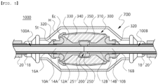
- FIG. 3 illustrates a cross-sectional view of the direct-current power cable system according to the present invention.
- a description will be provided for a direct-current power cable system configured with the direct-current power cable for underground installation being connected, illustrated in FIG. 1 .
- a direct-current power cable system 1000 may be configured to include a pair of direct-current power cables 100A and 100B and a cable joint box 700 that connects the pair of direct-current power cables 100A and 100B.
- the cable joint box 700 may be configured to include a conductor connection portion 200 that connects the conductors of the pair of direct-current power cables; a sleeve member 300 mounted to surround the conductor connection portion 200 and cable connection regions; and a housing H that accommodates the sleeve member 300 therein.
- the housing may be configured with a metal casing of a metal material.
- a space between the housing H of the cable joint box and the sleeve member 300 according to the present invention may be filled with a waterproofing material (not illustrated) or similar substance.
- the conductor connection portion 200 inside the cable joint box 700 connects the conductors 10A and 10B of the pair of direct-current power cables 100A and 100B by welding the ends of the conductors, or by applying a conductor sleeve 251, which may be pressed or connected to the conductor using fastening bolts.
- a corona shield 250 may be mounted on a conductor-connected portion, and the corona shield 250 is mounted to be horizontally level with the insulators of the pair of direct-current power cables 100A and 100B, and is electrically connected to the conductor sleeve 251 or the connected conductors 10A and 10B using braided wires or similar means.
- the corona shield 250 may be mounted using a fixing structure (not illustrated), such as a groove mounted on the insulator, to ensure that no level difference occurs with the insulating layers 14A and 14B of the pair of direct-current power cables 100A and 100B.
- the sleeve member 300 may be mounted to surround the insulating layers 14A and 14B of the pair of direct-current power cables 100A and 100B and the corona shield 250.
- the sleeve member 300 may be configured to include: a first electrode 310 disposed to surround the conductor connection portion and electrically connected to the conductor connection portion 200; a pair of second electrodes 320 provided each on both sides of the first electrode 310 along a cable length direction; an electric field alleviation layer 330 that surrounds the first electrode 310, at least a portion of the pair of second electrodes 320, and the insulating layer 16, and at least a portion thereof is disposed between the outer semiconductive layer 16 and the second electrodes 320 so that the second electrodes and the outer semiconductive layer are in a non-contact state, while being in contact with the outer semiconductive layer 16; a rubber insulating layer 340 that surrounds the electric field alleviation layer 330 and formed to remain in a non-contact state with the second electrodes 320; and a sleeve shielding layer 350 that surrounds the rubber insulating layer 340.
- the first electrode 310 and the pair of second electrodes 320 may be manufactured using a semiconductive material, such as semiconductive liquid silicone rubber (LSR) or semiconductive ethylene propylene rubber (EPDM).
- LSR semiconductive liquid silicone rubber
- EPDM semiconductive ethylene propylene rubber
- the first electrode 310 is electrically connected to the conductors 10A and 10B of the pair of direct-current power cables, serving as a so-called high-voltage electrode (high voltage semi-conductor).
- the pair of second electrodes 320 are each electrically connected to the outer semiconductive layers of the pair of direct-current power cables 100A and 100B through a semiconductive taping layer (St), described below, or similar, performing the role of a so-called deflector electrode (deflector semi-conductor). Accordingly, within the sleeve member, the electric field distribution is arranged along the area between the first electrode 310 and the second electrode 320.
- the shape of the first electrode 310 may be formed of a curved surface with rounded edges, and the shape of the second electrode 320 may have an inner surface formed of rounded curved surface that is in close contact with the electric field alleviation layer 330 of the sleeve member. Additionally, the shape, size, and material of the first electrode 310 and second electrode 320 may be appropriately adjusted to be designed to ensure that the electric field distribution between the first electrode 310 and the second electrode 320 does not become concentrated.
- the direct-current power cable system according to the present invention may be configured such that the pair of second electrodes 320 are separated from the sleeve shielding layer 350, which is disposed at an outermost portion of the sleeve member 300, to prevent contact with the sleeve shielding layer 350, and may be provided on both sides of the sleeve member 300.
- the sleeve shielding layer 350 is configured from a semiconductive material, similar to the first electrode 310 or the second electrode 320. As described above, the sleeve shielding layer 350 in the sleeve member 300 is provided spaced apart from the second electrode 320, which serves as a shielding electrode. However, optionally, the sleeve shielding layer 350 and the second electrode 320 may be formed to be electrically connected using electrical connection means, in which a semiconductive taping layer, a metal mesh, or similar means may be used as the electrical connection means.
- FIG. 4 illustrates a cross-sectional view of the direct-current power cable system when a cable joint box according to the present invention is used as a normal joint
- FIG. 5 illustrates a cross-sectional view of the direct-current power cable system when a cable joint box according to the present invention is used as an insulation joint.
- the cable joint box when the cable joint box according to the present invention is used as a normal joint, the cable joint box may be used so that both ends of the sleeve shielding layer 350 is electrically connected to the pair of second electrodes 320 on both sides using electrical connection means (Ec).
- the cable joint box when the cable joint box is used as an insulation joint, the cable joint box may be used so that only one end of the sleeve shielding layer 350 is electrically connected to one of the second electrodes 320 using the electrical connection means (Ec), while the other end of the sleeve shielding layer 350 and the remaining second electrode 320 are kept in an insulated state.
- an insulating barrel (not illustrated) may be provided in the middle of the housing H of a metal material, thereby an electrically insulated section being provided within the housing.
- a distance between both ends of the sleeve shielding layer 350 may be formed shorter than a distance between both ends of the rubber insulating layer 340 so that a path of a creepage distance from the sleeve shielding layer 350 to the second electrode 320 is formed in a stepped shape.
- a distance between both ends of the rubber insulating layer 340 may be formed shorter than a distance between both ends of the electric field alleviation layer so that the path of the creepage distance from the sleeve shielding layer 350 to the second electrode 320 is formed in a stepped shape. The detailed description thereof will be described below.
- the area between the sleeve shielding layer 350 and the second electrode 320 in the sleeve member 300 in the insulation joint needs to be insulated and have sufficient creepage distance to allow for sectional diagnosis of the cable system.
- the diagnostic device applies a test voltage to the shielding layer of the power cable system to diagnose fault signals. Measurement is only possible when the second electrode 320 and the sleeve shielding layer 350 in the sleeve member 300 within the insulation joint are separated, and a creepage distance exists. If the creepage distance between the sleeve shielding layer 350 and the second electrode 320 in the sleeve member 300 is not secured, sufficient voltage is not applied even when a test voltage is applied, making diagnosis impossible.
- the present invention enables smooth diagnostic operations for the power cable system by configuring the second electrode 320 and the sleeve shielding layer 350 that configure the sleeve member to be separated, allowing sectional diagnosis of the cable system.
- the rubber insulating layer 340 is manufactured from, for example, liquid silicone rubber (LSR) or ethylene propylene rubber (EPDM), thereby ensuring the insulating performance of the sleeve member 300.
- LSR liquid silicone rubber
- EPDM ethylene propylene rubber
- the electric field alleviation layer 330 is provided between the cable insulating layer 14 and the rubber insulating layer 340 to surround the first electrode 310 and at least a portion of the pair of second electrodes 320.
- the electric field alleviation layer 330 primarily performs an insulating function, but because the electric field alleviation layer 330 is configured with an insulating composition of higher electrical conductivity than the rubber insulating layer 340, when an excessive electric field is applied and microcurrents flow through the electric field alleviation layer 330, charges move in the direction of the electric field alleviation layer 330. This allows the charges to be discharged outside the sleeve member 300 through the second electrode 320 and the outer semiconductive layer 16 of the cable.
- the sleeve member 300 according to the present invention is provided with the aforementioned electric field alleviation layer 330 to enable the discharge of space charges as described above.
- the electric field alleviation layer 330 allows microcurrents to flow selectively according to a specific electric field value, between the conductors 10A and 10B and the outer semiconductive layers 16A and 16B of the ultra-high voltage direct-current power cable. When the space charges accumulate at a certain level or higher, this electric field alleviation layer 330 discharges the charges.
- the electric field alleviation layer 330 may have a volume resistivity that changes non-linearly under an electric field in the range of 10 1 0 to 2 ⁇ 10 1 7 ⁇ cm.
- the rubber insulating layer 340 may have a higher volume resistivity of 10 1 4 to 10 1 8 ⁇ cm.
- the meaning of the electric field alleviation layer 330 allowing microcurrents to selectively flow between the conductor 10 and the outer semiconductive layer 16 is as follows.
- the electric field alleviation layer 330 with the aforementioned physical properties, normally has a relatively high resistance and thus does not electrically connect the conductor 10 and the outer semiconductive layer 16.
- the electric field alleviation layer 330 may have an electrical characteristic where its resistance decreases non-linearly when an electric field of a predetermined level of higher is applied.
- the resistance of the electric field alleviation layer 330 decreases non-linearly, allowing charges to be discharged from the first electrode 310 to the second electrode 320 or the outer semiconductive layer 16.
- the electric field alleviation layer 330 may be manufactured from a material known as field grading material (FGM).
- FGM field grading material
- the second electrode 320 and the outer semiconductive layer 16 of the power cable are not in direct contact. However, by finishing with a semiconductive taping layer (St) configured by cross-winding a separate semiconductive tape before mounting the housing H, the second electrode 320 and the outer semiconductive layer 16 of the power cable may be electrically connected.
- St semiconductive taping layer
- housing H may also be finished to be mounted and grounded so that the housing H is connected to the metal shielding layer 18 of the power cable.
- the direct-current power cable system may prevent or minimize electric field distortion and the reduction of direct-current dielectric strength due to space charge accumulation in the sleeve member 300 by adjusting the shape of the electric field alleviation layer 330 and controlling the component content of the insulating composition that regulates the electrical conductivity of the electric field alleviation layer 330.
- a detailed description will be provided with reference to FIG. 6 .
- the electric field alleviation layer 330 and the rubber insulating layer 340 each have a stepped level difference S formed at both ends, and the stepped level difference S may be provided to be exposed outside both ends of the sleeve shielding layer 350.
- a distance between both ends of the sleeve shielding layer 350 may be formed shorter than a distance between both ends of the rubber insulating layer 340, and the distance between both ends of the rubber insulating layer 340 may be formed shorter than a distance between both ends of the electric field alleviation layer.
- the distance between both ends of the electric field alleviation layer 330, along the cross-section may be configured longer than that of the rubber insulating layer 340.
- This arrangement allows the sleeve shielding layer 350, the rubber insulating layer 340, and the electric field alleviation layer 330 to sequentially form the stepped level difference S, enabling the path of the creepage distance from the sleeve shielding layer to the second electrode to be formed as a stepped shape.
- the sleeve shielding layer 350 is spaced apart from the second electrode 320 to ensure a creepage distance l along the stepped path, which is a surface distance from each end of the sleeve shielding layer 350 to each second electrode 320, allowing for smooth diagnostic operations of the direct-current power cable system.
- the electric field alleviation layer 330 has relatively low resistance and dielectric strength properties, so caution should be taken to avoid excessive use. Accordingly, in the present invention, by configuring the thickness or outer diameter of each section of the electric field alleviation layer 330 differently in the length direction, it is possible to prevent dielectric strength reduction caused by an excessive proportion of the electric field alleviation layer 330, while also minimizing costs associated with reducing the amount of electric field alleviation layer 330 used.
- the electric field alleviation layer 330 is provided to surround the first electrode 310 and at least a portion of the second electrodes 320 disposed at the center portion.
- the electric field alleviation layer 330 is provided with an outer diameter variation section, where an outer diameter of the electric field alleviation layer 330 changes in the direction from the first electrode 310 toward the pair of second electrodes 320 disposed on both sides. Accordingly, compared to configuring an outer circumferential surface of the electric field alleviation layer 330 as flat, it is expected to reduce consumption of a material that configures the electric field alleviation layer 330 while still providing sufficient electric field alleviation effects due to charge movement.
- a slope ⁇ of an inclined section of the electric field alleviation layer 330 in the sleeve member 300 may be formed within a range of 5 to 45 degrees, preferably within 15 to 25 degrees.
- the electric field alleviation layer 330 may be configured to include: a first electrode covering portion 331 that surrounds the first electrode 310; a pair of connection portions 332 with a reduced outer diameter compared to the first electrode covering portion 331, extending from both sides of the first electrode covering portion 331 in the direction of the second electrodes; a pair of inclined portions 333 connected to the connection portions 332, with an increasing outer diameter in the direction of the second electrodes to have an inclined section; and a pair of second electrode covering portions 334 connected to the inclined portions 333, surrounding at least a portion of the second electrodes 320 and having at least a portion disposed between the outer semiconductive layer 16 and the second electrodes 320 so that the second electrodes 320 and the outer semiconductive layer 16 are in a non-contact state, while the at least a portion being in contact with the outer semiconductive layer 16.
- the rubber insulating layer 340 may be provided on the interface of the electric field alleviation layer 330 while satisfying the following Equation 1. D 2 mm ⁇ D 1 mm ⁇ D 3 mm
- the electric field alleviation layer 330 of the sleeve member 300 surrounds the first electrode 310, at least a portion of the second electrode 320, and the insulating layer, and is in close contact with an inner surface of the pair of second electrodes 320. At least a portion of electric field alleviation layer 330 is provided to be disposed between the second electrode and the outer semiconductive layer so that the second electrode and the outer semiconductive layer are in a non-contact state, and in contact with the outer semiconductive layer. Accordingly, the outer semiconductive layer of the pair of direct-current power cables 100A and 100B and the pair of second electrodes 320 may be mutually spaced apart by the electric field alleviation layer 330.
- a spacing distance t between the second electrode 320 and each outer semiconductive layer 16 may preferably be formed within a range of 2 millimeters (mm) to 10 millimeters (mm).
- the second electrode covering portion 343 is configured to include a second electrode lower side cover portion 334i disposed between the outer semiconductive layer 16 and the second electrode 320, and a second electrode upper side cover portion 334o surrounding at least a portion of an upper side of the second electrode 320.
- the second electrode 320 is semi-embedded within the electric field alleviation layer 330, thereby allowing the second electrode 320 to remain non-contact with the insulating layer 14 and outer semiconductive layer 16 of the power cable, as well as the rubber insulating layer 340 of the sleeve member.
- the second electrode lower side cover portion 334i which configures the second electrode covering portion 343 of the electric field alleviation layer 330, is omitted, a triple point where the second electrode 320, the outer semiconductive layer 16, and the electric field alleviation layer 330 all come into contact is generated. In this triple point, space charges may excessively accumulate, resulting in an electrically vulnerable portion.
- the electric field alleviation layer 330 may be composed of an insulating composition with higher electrical conductivity than the rubber insulating layer 340. It has been experimentally confirmed that, due to this electrical conductivity, the temperature of the electric field alleviation layer 330 may be controlled within a range of 20 to 90 degrees Celsius (°C) when an electric field of 10 to 30 kV/mm is applied to the electric field alleviation layer 330.
- the electrical conductivity of the rubber insulating layer 340 is 10 -12 to 10 -15 S/m (siemens per meter), and it is preferable that the electrical conductivity of the electric field alleviation layer 330 is greater than that of the rubber insulating layer 340.
- the electrical conductivity of the electric field alleviation layer 330 may be adjusted to be in the range of 5 to 10,000 times that of the rubber insulating layer 140.
- the electrical conductivity of the electric field alleviation layer 330 may be adjusted to 5 ⁇ 10 -14 to 10 -10 S/m by the insulating composition.
- the electric field alleviation layer 330 may be configured from an insulating composition that includes thermosetting rubber and a filler that induces nonlinear electrical behavior.
- the thermosetting rubber may be configured as liquid silicone rubber (LSR), ethylene propylene rubber (EPDM), or a mixture thereof, and lubricants, crosslinking agents, co-crosslinking agents, and antioxidants, etc. may in added into the mixture.
- fillers that induce nonlinear electrical behavior such as silicon carbide, may be used.
- conductive or semiconductive fillers may be further used to enhance properties.
- the electrical properties of the electric field alleviation layer 330 may be achieved, while satisfying the characteristic that when microcurrents cause a specific electric field value or more, the electrical conductivity significantly increases, allowing the charge to move along the electric field relaxation layer.
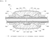
- FIG. 7 illustrates the movement direction of internal charges due to microcurrents within an electric field alleviation layer in the direct-current power cable system according to the present invention.
- FIG. 8 illustrates a simulation graph of the electric field distribution around the electric field alleviation layer 330 configuring the direct-current power cable system according to the present invention.
- the electric field distribution is uniformly spread between the first electrode 310 and the second electrode 320, and while the electric field is partially concentrated in the region where the thickness of the rubber insulating layer 340 decreases, it exhibits good performance in terms of electric field alleviation.
- the direct-current power cable system optimizes the size of the electric field alleviation layer surrounding the first electrode and the second electrode as described above in terms of the shape of the electric field alleviation layer, thereby providing sufficient electric field alleviation performance while preventing the volume of the electric field alleviation layer from becoming excessively large, which may result in cost reduction.
Landscapes
- Chemical & Material Sciences (AREA)
- Health & Medical Sciences (AREA)
- Chemical Kinetics & Catalysis (AREA)
- Medicinal Chemistry (AREA)
- Polymers & Plastics (AREA)
- Organic Chemistry (AREA)
- Physics & Mathematics (AREA)
- Spectroscopy & Molecular Physics (AREA)
- Cable Accessories (AREA)
Applications Claiming Priority (3)
| Application Number | Priority Date | Filing Date | Title |
|---|---|---|---|
| KR20220075474 | 2022-06-21 | ||
| KR1020230079091A KR20230175124A (ko) | 2022-06-21 | 2023-06-20 | 직류 전력케이블 시스템 |
| PCT/KR2023/008590 WO2023249399A1 (ko) | 2022-06-21 | 2023-06-21 | 직류 전력케이블 시스템 |
Publications (1)
| Publication Number | Publication Date |
|---|---|
| EP4546586A1 true EP4546586A1 (de) | 2025-04-30 |
Family
ID=89334199
Family Applications (1)
| Application Number | Title | Priority Date | Filing Date |
|---|---|---|---|
| EP23827509.3A Pending EP4546586A1 (de) | 2022-06-21 | 2023-06-21 | Gleichstrom-energiekabelsystem |
Country Status (3)
| Country | Link |
|---|---|
| EP (1) | EP4546586A1 (de) |
| KR (1) | KR20230175124A (de) |
| WO (1) | WO2023249399A1 (de) |
Family Cites Families (5)
| Publication number | Priority date | Publication date | Assignee | Title |
|---|---|---|---|---|
| WO2013004748A2 (en) * | 2011-07-05 | 2013-01-10 | Abb Research Ltd | A device for electric field control |
| JP6258715B2 (ja) * | 2014-01-30 | 2018-01-10 | 昭和電線ケーブルシステム株式会社 | 内側保護管及び電力ケーブルの中間接続部 |
| JP6823941B2 (ja) * | 2016-04-28 | 2021-02-03 | スリーエム イノベイティブ プロパティズ カンパニー | ケーブルの分岐構造、及び被覆処理具 |
| JP6737407B2 (ja) * | 2017-07-13 | 2020-08-05 | 住友電気工業株式会社 | 非オーム性組成物およびその製造方法、ケーブル中間接続用ユニット並びにケーブル終端接続用ユニット |
| KR102625952B1 (ko) * | 2018-12-07 | 2024-01-16 | 엘에스전선 주식회사 | 이종 도체 접합부를 포함하는 전력케이블, 이종 도체 접합방법 및 이종 도체 전력케이블 중간접속함 |
-
2023
- 2023-06-20 KR KR1020230079091A patent/KR20230175124A/ko active Pending
- 2023-06-21 EP EP23827509.3A patent/EP4546586A1/de active Pending
- 2023-06-21 WO PCT/KR2023/008590 patent/WO2023249399A1/ko not_active Ceased
Also Published As
| Publication number | Publication date |
|---|---|
| KR20230175124A (ko) | 2023-12-29 |
| WO2023249399A1 (ko) | 2023-12-28 |
Similar Documents
| Publication | Publication Date | Title |
|---|---|---|
| US8754329B2 (en) | High voltage direct current cable termination apparatus | |
| US3614300A (en) | Power cable with polypropylene covered ground-check strand | |
| GB2073480A (en) | Moisture-proof electric power cable | |
| KR102238971B1 (ko) | Dc용 케이블의 종단접속함 | |
| US10957469B2 (en) | High voltage three-phase cable | |
| US3843830A (en) | Electric cable with corrugated sheath and semi-conductive protective layer between the sheath and the core | |
| KR102386760B1 (ko) | 초고압 직류 전력케이블용 중간접속함 | |
| KR102386728B1 (ko) | 초고압 직류 전력케이블용 중간접속함 및 이를 포함하는 초고압 직류 전력케이블 접속시스템 | |
| EP3611737B1 (de) | Verbindungsdose für hochspannungsgleichstromkabel und dieselbe umfassendes hochspannungsgleichstromversorgungskabelsystem | |
| JP2022534190A (ja) | 遮水機能を有するhvdc電力ケーブル | |
| EP4546586A1 (de) | Gleichstrom-energiekabelsystem | |
| EP4546585A1 (de) | Gleichstromkabelsystem | |
| US3860741A (en) | Stress cone | |
| EP3882930A1 (de) | Ultrahochspannungsgleichstromkabelsystem | |
| KR20240148009A (ko) | 고전압 직류 전력케이블의 종단접속함 | |
| KR101594996B1 (ko) | 특고압용 절연 3심 케이블 | |
| KR20190114091A (ko) | 전력케이블의 종단접속함 | |
| AU2013251272B2 (en) | ROV cable insulation system | |
| WO1994025968A1 (en) | High-voltage line conductor for overhead lines for voltages of approximately 60 kv and higher | |
| KR20170105246A (ko) | 케이블 접속함용 조인트 슬리브 및 조인트 슬리브를 구비한 케이블 | |
| EP0848388B1 (de) | Abgeschirmtes Kabel | |
| KR20140115509A (ko) | Dc 케이블용 중간접속함 | |
| KR20150117528A (ko) | Dc용 케이블의 접속함 | |
| WO2018190497A1 (ko) | 초고압 직류 전력케이블용 증간접속함 및 이를 포함하는 초고압 직류 전력케이블 시스템 | |
| KR20230168228A (ko) | 전력케이블의 종단접속함 |
Legal Events
| Date | Code | Title | Description |
|---|---|---|---|
| STAA | Information on the status of an ep patent application or granted ep patent |
Free format text: STATUS: THE INTERNATIONAL PUBLICATION HAS BEEN MADE |
|
| PUAI | Public reference made under article 153(3) epc to a published international application that has entered the european phase |
Free format text: ORIGINAL CODE: 0009012 |
|
| STAA | Information on the status of an ep patent application or granted ep patent |
Free format text: STATUS: REQUEST FOR EXAMINATION WAS MADE |
|
| 17P | Request for examination filed |
Effective date: 20241122 |
|
| AK | Designated contracting states |
Kind code of ref document: A1 Designated state(s): AL AT BE BG CH CY CZ DE DK EE ES FI FR GB GR HR HU IE IS IT LI LT LU LV MC ME MK MT NL NO PL PT RO RS SE SI SK SM TR |
|
| DAV | Request for validation of the european patent (deleted) | ||
| DAX | Request for extension of the european patent (deleted) |