EP4559813A1 - Système de source d'énergie motrice hybride d'aéronef et son procédé de commande - Google Patents
Système de source d'énergie motrice hybride d'aéronef et son procédé de commande Download PDFInfo
- Publication number
- EP4559813A1 EP4559813A1 EP23842911.2A EP23842911A EP4559813A1 EP 4559813 A1 EP4559813 A1 EP 4559813A1 EP 23842911 A EP23842911 A EP 23842911A EP 4559813 A1 EP4559813 A1 EP 4559813A1
- Authority
- EP
- European Patent Office
- Prior art keywords
- fuel cell
- gas
- motor generator
- aircraft
- fuel
- Prior art date
- Legal status (The legal status is an assumption and is not a legal conclusion. Google has not performed a legal analysis and makes no representation as to the accuracy of the status listed.)
- Pending
Links
Images


Classifications
-
- H—ELECTRICITY
- H01—ELECTRIC ELEMENTS
- H01M—PROCESSES OR MEANS, e.g. BATTERIES, FOR THE DIRECT CONVERSION OF CHEMICAL ENERGY INTO ELECTRICAL ENERGY
- H01M8/00—Fuel cells; Manufacture thereof
- H01M8/04—Auxiliary arrangements, e.g. for control of pressure or for circulation of fluids
- H01M8/04082—Arrangements for control of reactant parameters, e.g. pressure or concentration
- H01M8/04089—Arrangements for control of reactant parameters, e.g. pressure or concentration of gaseous reactants
- H01M8/04111—Arrangements for control of reactant parameters, e.g. pressure or concentration of gaseous reactants using a compressor turbine assembly
-
- B—PERFORMING OPERATIONS; TRANSPORTING
- B64—AIRCRAFT; AVIATION; COSMONAUTICS
- B64D—EQUIPMENT FOR FITTING IN OR TO AIRCRAFT; FLIGHT SUITS; PARACHUTES; ARRANGEMENT OR MOUNTING OF POWER PLANTS OR PROPULSION TRANSMISSIONS IN AIRCRAFT
- B64D27/00—Arrangement or mounting of power plants in aircraft; Aircraft characterised by the type or position of power plants
- B64D27/02—Aircraft characterised by the type or position of power plants
- B64D27/10—Aircraft characterised by the type or position of power plants of gas-turbine type
-
- B—PERFORMING OPERATIONS; TRANSPORTING
- B64—AIRCRAFT; AVIATION; COSMONAUTICS
- B64D—EQUIPMENT FOR FITTING IN OR TO AIRCRAFT; FLIGHT SUITS; PARACHUTES; ARRANGEMENT OR MOUNTING OF POWER PLANTS OR PROPULSION TRANSMISSIONS IN AIRCRAFT
- B64D27/00—Arrangement or mounting of power plants in aircraft; Aircraft characterised by the type or position of power plants
- B64D27/02—Aircraft characterised by the type or position of power plants
- B64D27/16—Aircraft characterised by the type or position of power plants of jet type
-
- B—PERFORMING OPERATIONS; TRANSPORTING
- B64—AIRCRAFT; AVIATION; COSMONAUTICS
- B64D—EQUIPMENT FOR FITTING IN OR TO AIRCRAFT; FLIGHT SUITS; PARACHUTES; ARRANGEMENT OR MOUNTING OF POWER PLANTS OR PROPULSION TRANSMISSIONS IN AIRCRAFT
- B64D27/00—Arrangement or mounting of power plants in aircraft; Aircraft characterised by the type or position of power plants
- B64D27/02—Aircraft characterised by the type or position of power plants
- B64D27/30—Aircraft characterised by electric power plants
- B64D27/33—Hybrid electric aircraft
-
- B—PERFORMING OPERATIONS; TRANSPORTING
- B64—AIRCRAFT; AVIATION; COSMONAUTICS
- B64D—EQUIPMENT FOR FITTING IN OR TO AIRCRAFT; FLIGHT SUITS; PARACHUTES; ARRANGEMENT OR MOUNTING OF POWER PLANTS OR PROPULSION TRANSMISSIONS IN AIRCRAFT
- B64D27/00—Arrangement or mounting of power plants in aircraft; Aircraft characterised by the type or position of power plants
- B64D27/02—Aircraft characterised by the type or position of power plants
- B64D27/30—Aircraft characterised by electric power plants
- B64D27/35—Arrangements for on-board electric energy production, distribution, recovery or storage
- B64D27/355—Arrangements for on-board electric energy production, distribution, recovery or storage using fuel cells
-
- B—PERFORMING OPERATIONS; TRANSPORTING
- B64—AIRCRAFT; AVIATION; COSMONAUTICS
- B64D—EQUIPMENT FOR FITTING IN OR TO AIRCRAFT; FLIGHT SUITS; PARACHUTES; ARRANGEMENT OR MOUNTING OF POWER PLANTS OR PROPULSION TRANSMISSIONS IN AIRCRAFT
- B64D31/00—Power plant control systems; Arrangement of power plant control systems in aircraft
- B64D31/16—Power plant control systems; Arrangement of power plant control systems in aircraft for electric power plants
- B64D31/18—Power plant control systems; Arrangement of power plant control systems in aircraft for electric power plants for hybrid-electric power plants
-
- F—MECHANICAL ENGINEERING; LIGHTING; HEATING; WEAPONS; BLASTING
- F01—MACHINES OR ENGINES IN GENERAL; ENGINE PLANTS IN GENERAL; STEAM ENGINES
- F01K—STEAM ENGINE PLANTS; STEAM ACCUMULATORS; ENGINE PLANTS NOT OTHERWISE PROVIDED FOR; ENGINES USING SPECIAL WORKING FLUIDS OR CYCLES
- F01K23/00—Plants characterised by more than one engine delivering power external to the plant, the engines being driven by different fluids
- F01K23/02—Plants characterised by more than one engine delivering power external to the plant, the engines being driven by different fluids the engine cycles being thermally coupled
-
- F—MECHANICAL ENGINEERING; LIGHTING; HEATING; WEAPONS; BLASTING
- F02—COMBUSTION ENGINES; HOT-GAS OR COMBUSTION-PRODUCT ENGINE PLANTS
- F02K—JET-PROPULSION PLANTS
- F02K5/00—Plants including an engine, other than a gas turbine, driving a compressor or a ducted fan
-
- H—ELECTRICITY
- H01—ELECTRIC ELEMENTS
- H01M—PROCESSES OR MEANS, e.g. BATTERIES, FOR THE DIRECT CONVERSION OF CHEMICAL ENERGY INTO ELECTRICAL ENERGY
- H01M8/00—Fuel cells; Manufacture thereof
- H01M8/04—Auxiliary arrangements, e.g. for control of pressure or for circulation of fluids
- H01M8/04007—Auxiliary arrangements, e.g. for control of pressure or for circulation of fluids related to heat exchange
- H01M8/04014—Heat exchange using gaseous fluids; Heat exchange by combustion of reactants
-
- H—ELECTRICITY
- H01—ELECTRIC ELEMENTS
- H01M—PROCESSES OR MEANS, e.g. BATTERIES, FOR THE DIRECT CONVERSION OF CHEMICAL ENERGY INTO ELECTRICAL ENERGY
- H01M8/00—Fuel cells; Manufacture thereof
- H01M8/04—Auxiliary arrangements, e.g. for control of pressure or for circulation of fluids
- H01M8/04298—Processes for controlling fuel cells or fuel cell systems
- H01M8/04694—Processes for controlling fuel cells or fuel cell systems characterised by variables to be controlled
- H01M8/04858—Electric variables
- H01M8/04925—Power, energy, capacity or load
-
- F—MECHANICAL ENGINEERING; LIGHTING; HEATING; WEAPONS; BLASTING
- F05—INDEXING SCHEMES RELATING TO ENGINES OR PUMPS IN VARIOUS SUBCLASSES OF CLASSES F01-F04
- F05D—INDEXING SCHEME FOR ASPECTS RELATING TO NON-POSITIVE-DISPLACEMENT MACHINES OR ENGINES, GAS-TURBINES OR JET-PROPULSION PLANTS
- F05D2220/00—Application
- F05D2220/70—Application in combination with
- F05D2220/76—Application in combination with an electrical generator
-
- H—ELECTRICITY
- H01—ELECTRIC ELEMENTS
- H01M—PROCESSES OR MEANS, e.g. BATTERIES, FOR THE DIRECT CONVERSION OF CHEMICAL ENERGY INTO ELECTRICAL ENERGY
- H01M8/00—Fuel cells; Manufacture thereof
- H01M8/10—Fuel cells with solid electrolytes
- H01M2008/1095—Fuel cells with polymeric electrolytes
-
- H—ELECTRICITY
- H01—ELECTRIC ELEMENTS
- H01M—PROCESSES OR MEANS, e.g. BATTERIES, FOR THE DIRECT CONVERSION OF CHEMICAL ENERGY INTO ELECTRICAL ENERGY
- H01M2250/00—Fuel cells for particular applications; Specific features of fuel cell system
- H01M2250/20—Fuel cells in motive systems, e.g. vehicle, ship, plane
-
- H—ELECTRICITY
- H01—ELECTRIC ELEMENTS
- H01M—PROCESSES OR MEANS, e.g. BATTERIES, FOR THE DIRECT CONVERSION OF CHEMICAL ENERGY INTO ELECTRICAL ENERGY
- H01M2250/00—Fuel cells for particular applications; Specific features of fuel cell system
- H01M2250/40—Combination of fuel cells with other energy production systems
- H01M2250/407—Combination of fuel cells with mechanical energy generators
-
- Y—GENERAL TAGGING OF NEW TECHNOLOGICAL DEVELOPMENTS; GENERAL TAGGING OF CROSS-SECTIONAL TECHNOLOGIES SPANNING OVER SEVERAL SECTIONS OF THE IPC; TECHNICAL SUBJECTS COVERED BY FORMER USPC CROSS-REFERENCE ART COLLECTIONS [XRACs] AND DIGESTS
- Y02—TECHNOLOGIES OR APPLICATIONS FOR MITIGATION OR ADAPTATION AGAINST CLIMATE CHANGE
- Y02T—CLIMATE CHANGE MITIGATION TECHNOLOGIES RELATED TO TRANSPORTATION
- Y02T90/00—Enabling technologies or technologies with a potential or indirect contribution to GHG emissions mitigation
- Y02T90/40—Application of hydrogen technology to transportation, e.g. using fuel cells
Definitions
- the present disclosure relates to an aircraft hybrid motive power source system in which a gas turbine engine and a fuel cell are used together as motive power sources for thrust.
- a conventional gas turbine engine installed on an aircraft generates not only thrust of the aircraft but also electric power consumed by the aircraft by driving a generator.
- Patent Literature 1 JP 2006-153013 A
- the present disclosure has been made in view of the circumstances described above, and it is an object of the present disclosure to provide an aircraft hybrid motive power source system and a method for controlling same, which are capable of improving fuel economy.
- An aircraft hybrid motive power source system includes: a gas turbine engine mounted on an aircraft and including a low-pressure shaft and a high-pressure shaft as rotary shafts; a first motor generator drivingly connected to the high-pressure shaft; a second motor generator drivingly connected to the low-pressure shaft; a fuel cell to which a fuel gas and an oxidant gas are supplied; a fuel gas generator configured to generate the fuel gas from a raw material by heating using an exhaust gas from the gas turbine engine; and a controller configured to supply an electric power of the fuel cell obtained by a supply of the fuel gas to one of the first motor generator and the second motor generator, based on at least one of information indicating an operating status of the gas turbine engine and an electric power demand of the aircraft.
- the aircraft hybrid motive power source system may further include: a heat exchanger configured to heat a discharged object of the fuel cell and cool the fuel gas supplied to the fuel cell by heat exchange between the fuel gas and the discharged object of the fuel cell; and a turbocharger configured to compress and supply the oxidant gas to the fuel cell by being supplied with the discharged object of the fuel cell.
- the aircraft hybrid motive power source system may further include a heating device configured to preheat the raw material supplied to the fuel gas generator.
- An aircraft hybrid motive power source system includes: a gas turbine engine mounted on an aircraft and including a low pressure shaft and a high pressure shaft as rotary shafts; a first motor generator drivingly connected to the high pressure shaft; a second motor generator drivingly connected to the low pressure shaft; a fuel cell to which a fuel gas and an oxidant gas are supplied; a heat exchanger configured to heat a discharged object of the fuel cell by heat exchange between an exhaust gas from the gas turbine engine and the discharged object of the fuel cell; a turbocharger configured to compress and supply the oxidant gas to the fuel cell by being supplied with the discharged object of the fuel cell heated by the heat exchanger; a controller configured to supply an electric power of the fuel cell obtained by a supply of the fuel gas to one of the first motor generator and the second motor generator, based on at least one of information indicating an operating status of the gas turbine engine and an electric power demand of the aircraft.
- the turbocharger according to the first or second aspect may be an electric turbocharger having a third motor generator.
- the controller supplies an electric power of the electric turbocharger obtained by being supplyied with the discharged object of the fuel cell to one of the first motor generator and the second motor generator based on at least one of the information indicating the operating status of the gas turbine engine and the electric power demand of the aircraft.
- a method for controlling an aircraft hybrid motive power source system includes: generating a fuel gas for a fuel cell from a raw material by heating using an exhaust gas from a gas turbine engine which is mounted on an aircraft and includes a low pressure shaft and a high pressure shaft as rotary shafts; supplying the fuel gas to the fuel cell; and supplying an electric power of the fuel cell obtained by a supply of the fuel gas to one of a first motor generator drivingly connected to the high pressure shaft and a second motor generator drivingly connected to the low pressure shaft, based on at least one of information indicating an operating status of the gas turbine engine and an electric power demand of the aircraft.
- the controlling method according to the third aspect may further include: heating a discharged object of the fuel cell and cooling the fuel gas supplied to the fuel cell by heat exchange between the fuel gas and the discharged object of the fuel cell; and compressing and supplying an oxidant gas of the fuel cell from a compressor of a turbocharger to the fuel cell by supplying the heated discharged object of the fuel cell to a turbine of the turbocharger.
- the controlling method according to the third aspect may further include heating the raw material before generating the fuel gas from the raw material.
- a method for controlling an aircraft hybrid motive power source system includes: pressurizing a discharged object of a fuel cell by heating using heat exchange between the discharged object of the fuel cell and an exhaust gas from a gas turbine engine which is mounted on an aircraft and includes a low pressure shaft and a high pressure shaft as rotary shafts; supplying the pressurized discharged object of the fuel cell to a turbine of a turbocharger; supplying a fuel gas discharged from a compressor of the turbocharger to the fuel cell; and supplying an electric power of the fuel cell obtained by a supply of the fuel gas to one of a first motor generator drivingly connected to the high pressure shaft and a second motor generator drivingly connected to the low pressure shaft, based on at least one of information indicating an operating status of the gas turbine engine and an electric power demand of the aircraft.
- the turbocharger according to the third or fourth aspect may be an electric turbocharger having a third motor generator.
- an electric power of the electric turbocharger obtained by being supplied with the discharged object of the fuel cell is supplied to one of the first motor generator and the second motor generator.
- the aircraft hybrid motive power source system includes at least a gas turbine engine for aircraft, a fuel cell, and a controller. These are installed in an aircraft (not shown).
- the aircraft hybrid motive power source system utilizes the exhaust heat of the gas turbine engine for power generation of the fuel cell, and supplies the electric power obtained thereby to each device of the aircraft depending on the operating status of the aircraft.
- the devices to each of which the electric power of the fuel cell is supplied include a motor generator that is drivingly connected to the rotary shaft of the gas turbine engine.
- the electric power of the fuel cell is used not only as electric power for avionics, air conditioner and the like, but also as a motive power to assist the gas turbine engine.
- the aircraft hybrid motive power source system is simply referred to as a hybrid system
- the gas turbine engine is simply referred to as an engine.
- the engine according to the present embodiment include a turbofan engine, a turbojet engine, a turboprop engine, a turboshaft engine, and the like.
- the engine includes a low-pressure shaft as a rotary shaft for connecting the low-pressure compressor and the low-pressure turbine, and a high-pressure shaft as a rotary shaft for connecting the high-pressure compressor and the high-pressure turbine. That is, the engine according to the present embodiment is a multi-axis gas turbine engine.
- the hybrid system 10A generates fuel gas for a fuel cell using the heat of exhaust gas from the engine.
- the fuel cell generates electric power by the fuel gas supplied thereto.
- the hybrid system 10A uses the electric power obtained from the fuel cell as electric assist of the engine or power of the electric equipment according to the operating status of the aircraft. As a result, it is possible to improve the thermal efficiency of the gas turbine engine, improve fuel efficiency, reduce carbon emissions and the like.
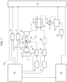
- FIG. 1 is a block diagram showing a configuration of a hybrid system 10A according to the present embodiment.
- the hybrid system 10A includes an engine 20, a first motor generator 31, a second motor generator 32, a fuel cell 40, a fuel gas generator 50, and a controller 60. These components are installed in an aircraft (not shown).
- the configuration of the engine 20 according to the present embodiment is basically same as that of a conventional turbofan engine. That is, the engine 20 is a two-shaft turbofan engine and includes a fan 21, a low-pressure compressor 22, a high-pressure compressor 23, a combustion chamber 24, a high-pressure turbine 25, and a low-pressure turbine 26.
- the low-pressure compressor 22, the low-pressure turbine 26, and the fan 21 are connected to each other via a low-pressure shaft (low-pressure spool) 27 as a rotary shaft.
- the fan 21 may be connected to the low-pressure shaft 27 via gears (not shown).
- the high-pressure compressor 23 and the high-pressure turbine 25 are connected to each other via a high-pressure shaft (high-pressure spool) 28 as a rotary shaft.
- the basic operations (e.g., gas compression, combustion, conversion of pressure energy to kinetic (rotational) energy, etc.) of the engine 20 are also the same as those of a conventional engine. That is, the fan 21 takes in gas as a working fluid from the front of the fan 21 and discharges it to the rear of the fan 21. A part of the gas that has passed through the fan 21 flows into the low-pressure compressor 22. The low-pressure compressor 22 compresses the gas that has flowed in from the fan 21 and discharges it to the high-pressure compressor 23. The high-pressure compressor 23 further compresses the gas having been compressed by the low-pressure compressor 22 and supplies it to the combustion chamber 24.
- gas compression e.g., gas compression, combustion, conversion of pressure energy to kinetic (rotational) energy, etc.
- the combustion chamber 24 combusts a mixed gas of the gas compressed by the high-pressure compressor 23 and the fuel supplied from the fuel tank 35 through the fuel supply device 36.
- the amount of fuel supplied is set by the controller 60.
- the fuel supply device 36 supplies the amount of fuel based on the set value to the combustion chamber 24.
- the combustion gas is discharged to the high-pressure turbine 25 and rotates the high-pressure turbine 25 with being expanding while it passes through the high-pressure turbine 25. This rotational energy is transmitted to the high-pressure compressor 23 via the high-pressure shaft 28, and thereby rotates the high-pressure compressor 23.
- the combustion gas passing through the high-pressure turbine 25 further expands while it passes through the low-pressure turbine 26, and rotates the low-pressure turbine 26.
- This rotational energy is transmitted to the low-pressure compressor 22 and the fan 21 via the low-pressure shaft 27, and thereby rotates the low-pressure compressor 22 and the fan 21.
- Part of the combustion gas passing through the low-pressure turbine 26 is supplied to a fuel gas generator 50 described later, and the remainder is discharged to the outside of the engine 20.
- the first motor generator (high-pressure shaft MG) 31 is drivingly connected to the high-pressure shaft 28 via the first drive train 33. That is, when the first motor generator 31 operates as a generator, a part of the rotational energy of the high-pressure shaft 28 is transmitted to the first motor generator 31 via the first drive train 33. Alternatively, when the first motor generator 31 operates as a motor, the rotational energy of the first motor generator 31 is transmitted to the high-pressure shaft 28 via the first drive train 33.
- the second motor generator (low-pressure shaft MG) 32 is drivingly connected to the low-pressure shaft 27 via the second drive train 34. That is, when the second motor generator 32 operates as a generator, a part of the rotational energy of the low-pressure shaft 27 is transmitted to the second motor generator 32 via the second drive train 34. Alternatively, when the second motor generator 32 operates as a motor, the rotational energy of the second motor generator 32 is transmitted to the low-pressure shaft 27 via the second drive train 34.
- the first motor generator 31 and the second motor generator 32 are accommodated, for example, in a well-known accessory gearbox (AGB, not shown) together with auxiliaries such as a fuel pump, a starter and the like.
- AGB accessory gearbox
- auxiliaries such as a fuel pump, a starter and the like.
- the location where these are accommodated is not limited to the AGB.
- the second motor generator 32 may be accommodated in a tail cone (not shown). In this case, the second motor generator 32 is drivingly connected to the rear end of the low-pressure shaft 27.
- the engine 20 may be a three-axis gas turbine engine further comprising an intermediate-pressure compressor (not shown), an intermediate-pressure turbine (not shown), and an intermediate-pressure shaft (medium-pressure spool, not shown) serving as a rotary shaft for connecting them.
- a motor generator (not shown) may also be drivingly connected to the medium-pressure shaft.
- the motor generator drivingly connected to the medium-pressure shaft also operates as a motor or generator based on at least one of information indicating the operating status of the engine 20 and the electric power demand of the aircraft.
- the fuel gas generator 50 generates fuel gas for the fuel cell 40 from a raw material by heating using exhaust gas from the engine 20.
- the raw material is, for example, ammonia. Since the hydrogen density per volume of ammonia is greater than that of hydrogen, it is suitable for storage in an aircraft subject to spatial limitations.
- the raw material is stored in the raw material tank 37 in a liquid state.
- the raw material is supplied to the fuel gas generator 50 by the raw material supply device 38.
- the raw material supply device 38 includes a pump such as a gear pump capable of adjusting the discharge amount.
- the amount of raw material supplied by the raw material supply device 38 is set by the controller 60.
- the raw material supply device 38 supplies the amount of raw material based on the set value to the fuel gas generator 50.
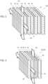
- FIG. 2 is a perspective view showing an example of a main part of the fuel gas generator 50.
- the fuel gas generator 50 is a so-called reformer or catalytic reactor.
- the fuel gas generator 50 includes, for example, a heat-medium channel 51 and a reaction channel 52.
- the heat-medium channel 51 and the reaction channel 52 are formed on, for example, one side surface and the other side surface of the plate member 53, respectively.
- the plate member 53 and the partition wall 54 are formed of a material having high thermal conductivity, such as metal, and are alternately stacked. Therefore, the heat-medium channel 51 and the reaction channel 52 are thermally coupled to each other through the plate member 53 or the partition wall 54.
- An inlet (upstream side) of the heat-medium channel 51 is connected to a duct (not shown) of the engine 20.
- An outlet (downstream side) of the heat-medium channel 51 is connected to a pipe (not shown) leading to the outside of the engine 20.
- an inlet (upstream side) of the reaction channel 52 is connected to an outlet of the raw material supply device 38.
- An outlet (downstream side) of the reaction channel 52 is connected to a primary inlet of the heat exchanger 55.
- a packing (not shown) carrying a catalyst is provided in the reaction channel 52.
- the catalyst may be carried on the inner surface of the reaction channel 52.
- the catalyst includes a component that promotes the hydrogen production reaction at relatively high temperatures (e.g., 300°C to 900°C).
- the catalyst may be nickel or ruthenium, or other metals or alloys.
- the exhaust gas EG of the engine 20 is supplied to the heat-medium channel 51.
- the fuel gas generator 50 is heated to about 450°C or higher, which is the operating temperature (light-off temperature) of the catalyst.
- ammonia gas AG as a raw material is supplied to the reaction channel 52 in this state, a mixed gas of hydrogen and nitrogen is generated by the catalytic reaction. This mixed gas is used as the fuel gas of the fuel cell 40.
- the temperature of the fuel gas immediately after it is generated by the fuel gas generator 50 is several hundred degrees Celsius. This temperature is higher than the operating temperature (e.g., 70°C to 90°C) of the fuel cell 40 assumed in the present embodiment. Therefore, in the present embodiment, the fuel gas is supplied to the fuel cell 40 after being cooled by the heat exchanger 55.
- the primary inlet of the heat exchanger 55 is connected to the outlet of the reaction channel 52 in the fuel gas generator 50.
- the primary outlet of the heat exchanger 55 is connected to the inlet of the first channel 46 in the fuel cell 40.
- the secondary inlet of the heat exchanger 55 is connected to the outlet of the second channel 48 in the fuel cell 40.
- the secondary outlet of the heat exchanger 55 is connected to a pipe (not shown) leading to the outside of the engine 20.
- Fuel gas flows through the primary side of the heat exchanger 55.
- steam which is a discharged object of the fuel cell 40, flows through the secondary side of the heat exchanger 55.
- heat is exchanged between the fuel gas and steam, and the fuel gas is cooled, while the steam is heated and discharged to the outside of the engine 20.
- the heat exchanger 55 may be omitted.
- the fuel cell 40 according to the present embodiment is a polymer electrolyte fuel cell (PEFC).
- the PEFC generates electric power by the reaction between hydrogen and oxygen.
- hydrogen is a component of the fuel gas
- oxygen is a component of the oxidant gas.
- the fuel cell according to the present embodiment is required to respond quickly (i.e., within a few seconds) to the set power value requested by the controller 60.
- the PEFC is an example of a fuel cell that satisfies such output performance. As long as the response performance described above can be obtained, the fuel cell 40 may be a fuel cell other than the PEFC.
- FIG. 3 is a perspective view showing the configuration of the unit cell 41 of the fuel cell 40 according to the present embodiment. As shown in this figure, the fuel cell 40 has separators 42 and unit cells 41. The separators 42 and the unit cells 41 are stacked alternately.
- the unit cell 41 includes an electrolyte membrane 43, an anode 45 as a fuel electrode, and a cathode 47 as an oxygen electrode (air electrode).
- the electrolyte membrane 43 is located between the anode 45 and the cathode 47.
- the electrolyte membrane 43 is a solid polymer membrane having cation conductivity, for example, a hydrocarbon polymer electrolyte membrane.
- the anode 45 and the cathode 47 are electrodes formed of a porous material carrying a catalyst.
- the porous material is, for example, carbon.
- the catalyst is, for example, platinum or an alloy containing platinum.
- Each separator 42 is a plate member arranged in parallel with the unit cell 41, and is a wall which separates adjacent unit cells 41.
- the separator 42 is formed of metal, carbon, conductive plastic, or the like.
- the separator 42 includes a first channel 46 through which the fuel gas FG flows on a surface in contact with the anode 45.
- the separator 42 also includes a second channel 48 through which the oxidant gas OG flows on a surface in contact with the cathode 47.
- the first channel 46 is formed, for example, of grooves extending in a predetermined direction.
- An inlet (upstream side) of the first channel 46 is connected to an outlet on the primary side of the heat exchanger 55.
- An outlet (downstream side) of the first channel 46 is connected to a pipe (not shown) leading to the outside of the engine 20.
- the second channel 48 is formed, for example, of grooves extending in a predetermined direction.
- An inlet (upstream side) of the second channel 48 is connected to an outlet of an air supplier 56, such as a pump or blower.
- An outlet (downstream side) of the second channel 48 is connected to a secondary inlet of the heat exchanger 55.
- the second channel 48 also functions as a discharge passage for discharge (i.e., water) generated in accordance with the generation of electric power by the fuel cell 40. That is, the discharged object from the fuel cell 40 is supplied to the secondary side of the heat exchanger 55.
- the fuel cell 40 When hydrogen as a fuel gas is supplied to the first channel 46 and air containing oxygen as an oxidant gas is supplied to the second channel 48, the fuel cell 40 generates electric power by a well-known chemical reaction. Water as a reaction product is discharged from the second channel 48 of the fuel cell 40. This water is supplied to the secondary side of the heat exchanger 55 and is used for cooling the fuel gas.
- the fuel gas which is supplied from the fuel gas generator 50, contains nitrogen gas.
- the nitrogen gas does not affect a series of chemical reactions in the fuel cell 40, or its influence is extremely small. Therefore, in the present embodiment, a device for separating the nitrogen gas from the fuel gas can be omitted.
- the electric power generated by the fuel cell 40 is distributed via the electric power system (power supply system) 61 to the equipment requiring electric power in that status.
- the equipment requiring electric power in that status is, for example, the first motor generator (high-voltage shaft MG) 31 described above. The details will be described later.
- the controller 60 is configured as a computer linked with FADEC (Full Authority Digital Engine Control).
- the controller 60 calculates the amount of electric power supply for the aircraft components 62 based on at least one of information indicating the operating status of the engine 20 (hereinafter referred to as operation status information) and the electric power demand of the aircraft, and supplies the electric power with the calculated amount to the aircraft components 62 via the electric power system 61.
- the operating status information of the engine 20 represents measured values of a pressure sensor, a temperature sensor, a flow sensor, etc., mounted on the engine 20, an outside temperature, an altitude, a flow rate of jet fuel supplied to the engine 20, a set value of an operation mode corresponding to an angular position of a power lever (i.e., PLA), etc.
- the electric power demand of the aircraft represents the electric power required for various types of aircraft components 62 such as avionics and air conditioning. The above-mentioned information and electric power demand changes every moment due to changes in operation modes and changes in the environment outside the aircraft.
- the aircraft components 62 includes the first motor generator 31 and the second motor generator 32. That is, the controller 60 supplies the electric power of the fuel cell 40 obtained by the supply of fuel gas to one of the first motor generator 31 and the second motor generator 32, based on at least one of the operation status information of the engine 20 and the electric power demand of the aircraft, and assists in driving them.
- the electric power obtained from the power generating equipment including the first motor generator 31, the second motor generator 32, and the fuel cell 40 is transmitted to the electric power system 61.
- the electric power system 61 is composed of various switches, relays, bus bars, etc., and functions as equipment for supplying and distributing electric power.
- the electric power system 61 is controlled by the controller 60, and supplies the electric power obtained from the power generating equipment to the aircraft components 62 such as avionics and air conditioning, or to the first motor generator 31 or the second motor generator 32 required to operate as an electric motor.
- FIG. 4 is a block diagram of a hybrid system 10B according to a modification of the first embodiment.
- the hybrid system 10B according to the present modification may include a turbocharger 70.
- the air supplier 56 connected to the second channel 48 of the fuel cell 40 is omitted.
- the air supplier 56 can be said to operate as a compressor 72 of the turbocharger 70.
- the turbocharger 70 includes a turbine 71 and a compressor 72 that rotates integrally with the turbine 71.
- An inlet of the turbine 71 is connected to the outlet on the secondary side of the heat exchanger 55.
- An outlet of the turbine 71 is also connected to, for example, an exhaust pipe (not shown) leading to the outside of the engine 20.
- the inlet of the compressor 72 is connected to, for example, an intake pipe (not shown) leading to the outside of the engine 20.
- the outlet of the compressor 72 is connected to the inlet (upstream side) of the second channel of the fuel cell 40.
- the inlet of the turbine 71 is connected to the outlet on the secondary side of the heat exchanger 55. Accordingly, the discharged object (i.e., water) of the fuel cell 40 that has passed through the heat exchanger 55 becomes steam, which is pressurized by heating in the heat exchanger 55, and flows into the turbine 71. The steam rotates the turbine 71, and the compressor 72 also rotates with this rotation.
- the discharged object i.e., water
- the compressor 72 in operation takes in and compresses air as oxidant gas.
- the compressed air is discharged from the compressor 72 and flows into the second channel 48 of the fuel cell 40. That is, the turbocharger 70 compresses and supplies the oxidant gas to the fuel cell 40 by being supplied with the discharged object of the fuel cell 40 having been heated by the heat exchanger 55. This promotes the generation of electric power by the fuel cell 40 and increases the amount of electric power obtained.
- the turbocharger 70 may be an electric turbocharger including a third motor generator 73.
- power can also be obtained from the third motor generator 73 by rotation of the turbine 71 due to supply of steam. Therefore, the total amount of power to be obtained increases.
- the controller 60 may supply the power obtained from the third motor generator 73 to one of the first motor generator 31 and the second motor generator 32 based on at least one of the operating status information of the engine 20 and the electric power demand of the aircraft.
- the hybrid system 10A (10B) may further include a heating device 57.
- the heating device 57 includes a well-known configuration including a combustor or an electric heater.
- the heating device 57 preheats the raw material supplied to the fuel gas generator 50.
- the raw material is heated to a temperature at which the catalytic reaction proceeds without receiving heat from the heat-medium channel 51 in the reaction channel 52 of the fuel gas generator 50.
- the raw material heated to this temperature is decomposed into fuel gas in the reaction channel 52 and supplied to the fuel cell 40.
- FIG. 5 is a diagram showing the operation states of devices in an example of the operation modes of the hybrid system according to the present embodiment.
- the high-pressure shaft MG refers to the first motor generator 31
- the low-pressure shaft MG refers to the second motor generator 32.
- M in the frame means that the motor generator is operating as a motor
- G in the frame means that the motor generator is operating as a generator.
- the turbocharger 70 in this example is an electric turbocharger and includes a third motor generator.
- the controller 60 acquires, as needed, the operating status information of the engine 20 and the electric power demand of the aircraft.
- the controller 60 also acquires in advance the maximum amount of electric power that can be generated by the second motor generator 32.
- the controller 60 sets the amount of electric power generated by the second motor generator 32 within the range of the above-described maximum amount of electric power, and sets the amount of raw material supplied by the raw material supply device 38 and the amount of oxidant gas supplied by the air supplier 56 (or the turbocharger 70). That is, the controller 60 sets the distribution of the amount of power generated by the second motor generator 32 and the amount of power generated by the fuel cell 40.
- the raw material supply device 38 and the heating device 57 are operated, and a raw material with high temperature is supplied to the reaction channel 52 of the fuel gas generator 50. While the raw material flows through the reaction channel 52, the reaction channel 52 is heated, and the temperature in the reaction channel 52 reaches the operating temperature of the catalyst. As a result, the catalytic reaction proceeds, and the fuel gas for the fuel cell 40 is generated from the raw material. The generated fuel gas is cooled by the heat exchanger and supplied to the first channel 46 of the fuel cell 40.
- the turbocharger 70 also operates by receiving the electric power from the fuel cell 40, and the air, which is the oxidant gas, is compressed and supplied to the second channel 48 of the fuel cell 40.
- the fuel cell 40 electric power is generated by being supplied with the fuel gas and the oxidant gas.
- the generated electric power is transmitted to the electric power system 61, and is supplied to the equipment requiring electric power in this operation mode under the control of the controller 60.
- the aircraft In this mode, the aircraft is taxiing in an airport.
- the engine 20 starts combustion of jet fuel and rotates the fan 21.
- the electric power of the fuel cell 40 is supplied to the first motor generator (high-pressure shaft MG) 31 to assist the rotation of the high-pressure shaft 28. This increases the compression ratio of the working fluid in the high-pressure compressor 23, thereby improving thermal efficiency.
- part of the exhaust gas from the engine 20 flows into the heat-medium channel 51 of the fuel gas generator 50, and the heat-medium channel 51 and the reaction channel 52 are heated to a temperature equal to or higher than the operating temperature of the catalyst.
- the amount of raw material set by the control unit 60 is supplied from the raw material supply device 38 to the heated reaction channel 52, thereby generating a desired amount of fuel gas.
- the turbocharger 70 operates also in the taxiing mode. Accordingly, electric power is generated in the fuel cell 40, and a part of the generated electric power is supplied to the first motor generator (high-voltage shaft MG) 31. The other part of the generated electric power is supplied to the aircraft components 62.
- an aircraft is taxiing in an airport.
- operation of the engine 20 by combustion is stopped.
- the heating device 57 and the turbocharger 70 operate to generate electric power for the fuel cell 40.
- the electric power of the fuel cell 40 is supplied to a second motor generator (low-pressure shaft MG) 32, and the second motor generator 32 operates as an electric motor.
- the low-pressure shaft 27 rotates, and the fan 21 rotates. That is, thrust for taxiing is obtained. Since jet fuel is not consumed, the consumption of jet fuel can be reduced. In other words, fuel economy can be improved.
- the thrust obtained by the engine 20 is maximized.
- the electric power of the fuel cell 40 is supplied to the first motor generator 31, and the first motor generator 31 assists the rotation of the high-pressure shaft 28.
- the temperature of the combustion gas at the inlet of the high-pressure turbine 25 is lowered, thereby extending the life of the high-pressure turbine 25.
- the thrust obtained by the engine 20 is maximized in this mode.
- the electric power of the fuel cell 40 is supplied to the aircraft components 62 and not to the first motor generator 31.
- the thermal efficiency of the engine 20 becomes highest, and the second motor generator 32 can be used as a generator. Since the aircraft components 62 can be supplied with the electric power of the second motor generator 32, all the devices for operating the fuel cell 40 and the fuel cell 40 are stopped.
- the output and thrust of the engine 20 are reduced. Since the engine 20 operates in a low-speed range, the thermal efficiency deteriorates if left as is.
- the fuel cell 40 is operated and its electric power is supplied to the first motor generator 31. Further, the second motor generator is operated as a generator and its electric power is also supplied to the first motor generator 31. As a result, thermal efficiency can be improved and fuel economy can be improved.
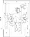
- FIG. 6 is a block diagram showing a configuration of a hybrid system 10C according to the second embodiment.
- the hybrid system 10C uses the heat of the exhaust gas of the engine 20 to heat the discharged object of the fuel cell 40. Therefore, as shown in FIG. 6 , the exhaust gas of the engine 20 is supplied to the primary inlet of the heat exchanger 55. Further, the fuel gas generator 50 according to the first embodiment is omitted, and hydrogen gas as the fuel gas is supplied directly to the first channel 46 of the fuel cell 40.
- Other configurations are the same as those of the first embodiment, and operate in the same manner as in the first embodiment. Therefore, the same effects as in the first embodiment can be obtained.
- the gas turbine engine and the fuel cell are used together as the motive power source of the thrust.
- the engine is assisted by the electric power of the fuel cell based on at least one of information indicating the operating status of the engine and the power demand of the aircraft.
- the heat of exhaust gas from the engine 20, which until now has simply been discarde is used. Therefore, the fuel economy can be improved. Also, carbon emissions can be reduced because carbon-free fuel is used as the fuel for generating thrust or power.
- the present disclosure can contribute, for example, to Goal 7 of the Sustainable Development Goals "Ensure access to affordable, reliable and sustainable modern energy for all.”
Landscapes
- Engineering & Computer Science (AREA)
- Aviation & Aerospace Engineering (AREA)
- Chemical & Material Sciences (AREA)
- Life Sciences & Earth Sciences (AREA)
- Combustion & Propulsion (AREA)
- Manufacturing & Machinery (AREA)
- Sustainable Development (AREA)
- Sustainable Energy (AREA)
- Chemical Kinetics & Catalysis (AREA)
- Electrochemistry (AREA)
- General Chemical & Material Sciences (AREA)
- Mechanical Engineering (AREA)
- General Engineering & Computer Science (AREA)
- Fuel Cell (AREA)
Applications Claiming Priority (2)
| Application Number | Priority Date | Filing Date | Title |
|---|---|---|---|
| JP2022116250 | 2022-07-21 | ||
| PCT/JP2023/025869 WO2024018988A1 (fr) | 2022-07-21 | 2023-07-13 | Système de source d'énergie motrice hybride d'aéronef et son procédé de commande |
Publications (1)
| Publication Number | Publication Date |
|---|---|
| EP4559813A1 true EP4559813A1 (fr) | 2025-05-28 |
Family
ID=89617639
Family Applications (1)
| Application Number | Title | Priority Date | Filing Date |
|---|---|---|---|
| EP23842911.2A Pending EP4559813A1 (fr) | 2022-07-21 | 2023-07-13 | Système de source d'énergie motrice hybride d'aéronef et son procédé de commande |
Country Status (4)
| Country | Link |
|---|---|
| US (1) | US12559247B2 (fr) |
| EP (1) | EP4559813A1 (fr) |
| JP (1) | JPWO2024018988A1 (fr) |
| WO (1) | WO2024018988A1 (fr) |
Families Citing this family (3)
| Publication number | Priority date | Publication date | Assignee | Title |
|---|---|---|---|---|
| US12583605B2 (en) | 2024-03-22 | 2026-03-24 | Rtx Corporation | Fast thrust response using optimal power splitting in hybrid electric aircraft |
| CN119329761B (zh) * | 2024-12-19 | 2025-06-24 | 南京航空航天大学 | 功热电耦合的氢能混合动力飞行器能量生成与管理系统 |
| CN119778101B (zh) * | 2025-01-27 | 2025-11-04 | 中国航发沈阳发动机研究所 | 一种内置电机的航空发动机 |
Family Cites Families (10)
| Publication number | Priority date | Publication date | Assignee | Title |
|---|---|---|---|---|
| JPH11200888A (ja) * | 1998-01-19 | 1999-07-27 | Mitsubishi Heavy Ind Ltd | 燃料電池式タービンエンジン |
| FR2878287B1 (fr) | 2004-11-25 | 2009-05-22 | Snecma Moteurs Sa | Turboreacteur double corps double flux avec generateur de courant electrique arriere |
| JP4092728B2 (ja) * | 2005-01-25 | 2008-05-28 | 独立行政法人 宇宙航空研究開発機構 | 航空機用推進システム |
| GB201418685D0 (en) * | 2014-10-21 | 2014-12-03 | Rolls Royce Plc | Gas turbine engine fuel system |
| WO2018042703A1 (fr) * | 2016-09-01 | 2018-03-08 | 株式会社Ihi | Système d'évacuation de chaleur pour générateur électrique embarqué |
| US10208675B2 (en) * | 2017-03-15 | 2019-02-19 | The Boeing Company | Hybrid drive system for transferring power from a gas turbine engine of an aircraft |
| EP3693571B1 (fr) * | 2019-02-05 | 2022-11-02 | Raytheon Technologies Corporation | Commande de fonctionnement transitoire d'un moteur à turbine à gaz hybride |
| WO2023026016A1 (fr) * | 2021-08-27 | 2023-03-02 | Zeroavia Limited | Gestion de décharge par effet couronne pour aéronef alimenté par pile à combustible à hydrogène |
| US20240254898A1 (en) * | 2023-01-27 | 2024-08-01 | Raytneon Technologies Corporation | Power electronics waste heat recovery in recuperation cycle |
| US11933232B1 (en) * | 2023-02-21 | 2024-03-19 | General Electric Company | Hybrid-electric gas turbine engine and method of operating |
-
2023
- 2023-07-13 EP EP23842911.2A patent/EP4559813A1/fr active Pending
- 2023-07-13 WO PCT/JP2023/025869 patent/WO2024018988A1/fr not_active Ceased
- 2023-07-13 JP JP2024535057A patent/JPWO2024018988A1/ja active Pending
-
2025
- 2025-01-10 US US19/016,563 patent/US12559247B2/en active Active
Also Published As
| Publication number | Publication date |
|---|---|
| WO2024018988A1 (fr) | 2024-01-25 |
| JPWO2024018988A1 (fr) | 2024-01-25 |
| US12559247B2 (en) | 2026-02-24 |
| US20250145302A1 (en) | 2025-05-08 |
Similar Documents
| Publication | Publication Date | Title |
|---|---|---|
| US12559247B2 (en) | Aircraft hybrid motive power source system and method for controlling same | |
| CN100438162C (zh) | 混合式燃料电池-脉冲引爆动力装置 | |
| US8623566B2 (en) | Aircraft fuel cell system | |
| EP4147974B1 (fr) | Systèmes d'hydrogène pour systèmes de contrôle environnemental à bord d'un aéronef | |
| EP4261961B1 (fr) | Système d'alimentation d'aéronef alimenté en hydrogène | |
| Guo et al. | Performance analysis of a turbofan engine integrated with solid oxide fuel cells based on Al-H2O hydrogen production for more electric long-endurance UAVs | |
| EP4273379A1 (fr) | Système de conversion d'énergie d'hydrogène | |
| WO2012045031A1 (fr) | Système de réservoir à combustible d'avion | |
| Wu et al. | Fuel cell applications on more electrical aircraft | |
| US20230211887A1 (en) | Control of a propulsion system having a fuel cell | |
| EP4092258A1 (fr) | Système de commande pour un ensemble pile à combustible et chambre de combustion de moteur | |
| US12255363B2 (en) | Integrated fuel cell and combustor assembly | |
| EP4575203A1 (fr) | Centrale d'aeronef a moteur electrique alimente par pile a combustible | |
| Santin et al. | Technological aspects of gas turbine and fuel cell hybrid systems for aircraft: a review | |
| US20230220783A1 (en) | Power source for an aircraft | |
| RU2492116C1 (ru) | Авиационная силовая установка на базе топливных элементов | |
| CN121296281A (zh) | 一种在燃烧室集成火焰燃料电池的涡轮发动机混动系统 | |
| US20240286754A1 (en) | Fuel tank inerting system | |
| US12584445B2 (en) | Gas turbine engine and fuel cell assembly | |
| US12270340B2 (en) | Gas turbine engine and fuel cell assembly | |
| US12261334B2 (en) | Gas turbine engine and fuel cell assembly | |
| US20250389231A1 (en) | Fuel systems for gas turbine engines | |
| US20240291000A1 (en) | Gas turbine engine and fuel cell assembly | |
| CN121803334A (zh) | 涡扇发动机与燃料电池混合动力系统 | |
| Tang et al. | System Modeling of FLyCLEEN Gas Turbine-Solid Oxide Fuel Cell Aircraft Engine Concept |
Legal Events
| Date | Code | Title | Description |
|---|---|---|---|
| STAA | Information on the status of an ep patent application or granted ep patent |
Free format text: STATUS: THE INTERNATIONAL PUBLICATION HAS BEEN MADE |
|
| PUAI | Public reference made under article 153(3) epc to a published international application that has entered the european phase |
Free format text: ORIGINAL CODE: 0009012 |
|
| STAA | Information on the status of an ep patent application or granted ep patent |
Free format text: STATUS: REQUEST FOR EXAMINATION WAS MADE |
|
| 17P | Request for examination filed |
Effective date: 20250221 |
|
| AK | Designated contracting states |
Kind code of ref document: A1 Designated state(s): AL AT BE BG CH CY CZ DE DK EE ES FI FR GB GR HR HU IE IS IT LI LT LU LV MC ME MK MT NL NO PL PT RO RS SE SI SK SM TR |
|
| DAV | Request for validation of the european patent (deleted) | ||
| DAX | Request for extension of the european patent (deleted) |