EP4563265A1 - Appareil d'alimentation en filet maillé - Google Patents
Appareil d'alimentation en filet maillé Download PDFInfo
- Publication number
- EP4563265A1 EP4563265A1 EP24214491.3A EP24214491A EP4563265A1 EP 4563265 A1 EP4563265 A1 EP 4563265A1 EP 24214491 A EP24214491 A EP 24214491A EP 4563265 A1 EP4563265 A1 EP 4563265A1
- Authority
- EP
- European Patent Office
- Prior art keywords
- mesh net
- mesh
- stacked
- nets
- unit
- Prior art date
- Legal status (The legal status is an assumption and is not a legal conclusion. Google has not performed a legal analysis and makes no representation as to the accuracy of the status listed.)
- Pending
Links
Images


Classifications
-
- B—PERFORMING OPERATIONS; TRANSPORTING
- B22—CASTING; POWDER METALLURGY
- B22D—CASTING OF METALS; CASTING OF OTHER SUBSTANCES BY THE SAME PROCESSES OR DEVICES
- B22D43/00—Mechanical cleaning, e.g. skimming of molten metals
- B22D43/001—Retaining slag during pouring molten metal
- B22D43/004—Retaining slag during pouring molten metal by using filtering means
-
- B—PERFORMING OPERATIONS; TRANSPORTING
- B22—CASTING; POWDER METALLURGY
- B22C—FOUNDRY MOULDING
- B22C9/00—Moulds or cores; Moulding processes
- B22C9/08—Features with respect to supply of molten metal, e.g. ingates, circular gates, skim gates
- B22C9/086—Filters
-
- B—PERFORMING OPERATIONS; TRANSPORTING
- B22—CASTING; POWDER METALLURGY
- B22D—CASTING OF METALS; CASTING OF OTHER SUBSTANCES BY THE SAME PROCESSES OR DEVICES
- B22D18/00—Pressure casting; Vacuum casting
- B22D18/04—Low pressure casting, i.e. making use of pressures up to a few bars to fill the mould
-
- B—PERFORMING OPERATIONS; TRANSPORTING
- B22—CASTING; POWDER METALLURGY
- B22D—CASTING OF METALS; CASTING OF OTHER SUBSTANCES BY THE SAME PROCESSES OR DEVICES
- B22D46/00—Controlling, supervising, not restricted to casting covered by a single main group, e.g. for safety reasons
Definitions
- the present disclosure relates to a mesh net supply apparatus that is capable of supplying mesh nets adapted to remove foreign substances upon the injection of a molten material into a casting mold.
- a low-pressure casting machine produces a tense cast material with no wrinkles, that is, a cast material with no slag, and through such a low-pressure casting machine, products such as aluminum wheels are cast.
- the low-pressure casting machine is configured to allow a holding furnace in which a molten metal such as aluminum used for casting is stored to be located on the bottom of a lower mold part of a mold divided into the lower mold part and an upper mold part, and in this case, the mold and the holding furnace are connected to each other by means of a stalk.
- the molten metal passes through the stalk and a pouring gate of the lower mold part and is then fed to a cavity of the mold.
- a filter which is made of steel meshes, fiber glass, ceramic foams, etc., is located on the pouring gate.
- the filter is automatically mounted on the pouring gate through an automatic filter supply apparatus, and in this case, one filter is normally mounted on the pouring gate.
- one filter is normally mounted on the pouring gate.
- two stacked filters may be frequently mounted erroneously on the pouring gate.
- the molten metal does not flow smoothly to the casting mold due to the resistances of meshes of the filter in a process where it passes through the filter, and therefore, there is a need to develop a new filter supply apparatus capable of solving such a problem.
- Patent literature Korean Patent Application Laid-open No. 10-2022-0159822 (December 5, 2022 )
- the present disclosure has been made in view of the above-mentioned problems occurring in the related art, and it is an object of the present disclosure to provide a mesh net supply apparatus that is capable of allowing mesh nets to be supplied one by one, while at least two stacked mesh nets among the mesh nets are not supplied, so that in a process where a molten metal passes through the mesh net and is injected into a casting mold, the molten metal flows smoothly, without any trouble.
- a mesh net supply apparatus for supplying mesh nets adapted to remove foreign substances upon the injection of a molten material to a casting mold, including: a first table for placing the mesh nets multi-stacked on top of one another on a plurality of positions thereof; an upper table having a mesh net through hole adapted to allow the topmost mesh net among the multi-stacked mesh nets to be exposed and pass therethrough in an upward direction; a gripping unit for gripping the mesh net exposed from the mesh net through hole; an elevating unit for moving the gripping unit upwards and downwards; a shuttle unit for transferring the gripping unit and the elevating unit; and a plurality of separation plates located around the mesh net through hole on the upper table in such a way as to be locked onto the periphery of the mesh net if the gripping unit moves downwards, grips the mesh net, and lifts the mesh net upwards, so that after the periphery of the mesh net is elastically bent, the
- each mesh net may include a cup-shaped mesh net body and a flange extending from the periphery of the mesh net body so that the flange of the mesh net is located under the plurality of separation plates before the mesh net is lifted, and if the mesh net moves upwards by means of the gripping unit, the flange is bent downwards by means of the plurality of separation plates to allow the mesh net to be lifted.
- each separation plate may have an end portion extending from one side thereof toward the mesh net through hole in such a way as to be located inside the mesh net through hole.
- the mesh net supply apparatus may further include a mesh net lifting unit located around the first table to move the multi-stacked mesh nets upwards and downwards, wherein the upper table has a height sensor adapted to sense a height of the mesh net exposed from the mesh net through hole, and the mesh net lifting unit moves the stacked mesh nets upwards and downwards according to the sensed value of the height sensor.
- the mesh net lifting unit may include: a lifting driver; a first lifting block reciprocating along the lifting driver; a second lifting block for supporting the underside of the bottommost mesh net among the multi-stacked mesh nets; and elastic members placed between the first lifting block and the second lifting block.
- the first table may comprise: a plurality of incised grooves passing therethrough in a thickness direction thereof in such a way as to be open toward the outside so that the underside of the mesh net is brought into contact with top of the first table around the incised groove; and a plurality of bar-shaped guides adapted to come into contact with the peripheries of the multi-stacked mesh nets and support the multi-stacked mesh nets.
- the first lifting block and the second lifting block may pass through the incised groove and move upwards and downwards by means of the operation of the lifting driver.
- the gripping unit may include: a chuck base; a plurality of gripping jaws coupled to the chuck base in such a way as to be spaced apart from one another along the circumferential direction of the mesh net body to move to the mesh net body and grip the mesh net body; and gripping actuators located on the chuck base in such a way as to allow the plurality of gripping jaws to be close to or spaced apart from the mesh net body.
- the elevating unit may include: an elevating actuator; and an elevating plate connected to the elevating actuator in such a way to move upwards and downwards, while locating the chuck base connected to the underside thereof, the chuck base may include a pusher adapted to pressurize the mesh net body downwards by means of the operation of the elevating unit, and between the chuck base and the elevating plate may be disposed elastic members to allow the pusher to elastically pressurize the mesh net body.
- the mesh net supply apparatus may further include: a second table located at a position spaced apart from the first table to allow the mesh net transferred through the shuttle unit to be seated on top thereof; a stacking sensor located on the upper table to irradiate light toward the mesh net gripped by the gripping unit and sense whether at least two or more stacked mesh nets are gripped by the gripping unit through the light reflected on the mesh nets; and a collection container located between the first table and the second table to separate and collect the at least two or more stacked mesh nets if the at least two or more stacked mesh nets are sensed through the stacking sensor.
- the first table and the second table may rotate by means of respective drivers and be provided in the form of turn tables on which the plurality of positions where the mesh nets are multi-stacked on top of one another are spaced apart from one another along the circumferential directions of the first table and the second table.
- a mesh net supply apparatus serves to supply mesh nets adapted to remove foreign substances upon the injection of a molten material into a casting mold, one by one, without any supply of at least two or more mesh nets stacked on top of each other.
- the mesh net supply apparatus can supply the mesh nets one by one.
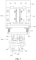
- the mesh net supply apparatus is adapted to supply mesh nets adapted to remove foreign substances upon the injection of a molten material into a casting mold and includes a first table 100, an upper table 200, a gripping unit 300, an elevating unit 400, a shuttle unit 500, a mesh net lifting unit 600, and a second table 700.
- a mesh net 10 includes a cup-shaped mesh net body 11 and a flange 12 extending from the periphery of the mesh net body 11 and is made of a metal or ceramic material so that it can be elastically deformed to a given degree.
- a plurality of mesh nets 10 are multi-stacked on top of one another on the first table 100, and next, they are transferred to a plurality of points of the second table 700 one by one by means of various components as will be discussed later and then move to the casting mold at a time.
- the first table 100 is located on a frame 50 and allows the plurality of mesh nets 10 to be multi-stacked on top of one another.
- the first table 100 has the shape of, for example, a circular plate as a turn table rotating by a driving part such as a driving motor.
- the plurality of mesh nets 10 are multi-stacked on top of one another on top of the first table 100, and in this case, a plurality of positions where the plurality of mesh nets 10 are multi-stacked on top of one another are spaced apart from one another along the circumferential direction of the first table 100.
- the first table 100 has a plurality of bar-shaped guides 110 adapted to come into contact with the peripheries of the plurality of mesh nets 10 multi-stacked on top of one another so that the multi-stacked mesh nets 100 are prevented from falling down.
- the first table 100 has a plurality of incised grooves 120 passing therethrough in a thickness direction thereof in such a way as to be open toward the outside.
- the number of incised grooves 120 corresponds to the plurality of positions where the plurality of multi-stacked mesh nets 10 are spaced apart from one another along the circumferential direction of the first table 100. That is, as shown in the drawings, if the plurality of mesh nets 10 are multi-stacked on top of one another on four positions of the first table 100, the first table 100 has four incised grooves 120.
- the bottommost mesh net 10 among the multi-stacked mesh nets 10 is being brought into contact with top of the first table 100 above each incised groove 120. That is, the bottommost mesh net 10 communicates with a space below the first table 100 through the corresponding incised groove 120.
- the upper table 200 is fixedly located on the frame 50 at a position spaced apart from the first table 100.
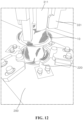
- the upper table 200 has a mesh net through hole 210 through which the topmost mesh net 10 among the multi-stacked mesh nets 10 is exposed to move upwards.
- the mesh net lifting unit 600 as will be discussed later operates to lift up the corresponding multi-stacked mesh net supply body so that the topmost mesh net 10 is exposed to the outside through the mesh net through hole 210. After that, the exposed mesh net 10 is gripped by means of the gripping unit 30 as will be discussed later and lifted upwards.
- the mesh net supply body represents one of the four positions where the multi-stacked mesh nets 10 are located.
- the upper table 200 has a plurality of separation plates 220 fixed thereto around the mesh net through hole 210 in such a way as to be spaced apart from one another along the circumferential direction of the mesh net through hole 210.
- the separation plates 220 serve to allow only one mesh net 10, not at least two or more stacked mesh nets 10, to be lifted, when the topmost mesh net 10 is gripped by means of the gripping unit 300, moves upwards through the operation of the elevating unit 400, and is lifted upwards.
- each separation plate 220 has a protruding end portion extending from one side thereof in such a way as to be located inside the mesh net through hole 210.
- each separation plate 220 includes a separation plate body 221 fixed to the upper table 200 by means of screw-fastening and a separation protrusion 224 extending from one side thereof in such a way as to be located inside the mesh net through hole 210.
- a separation plate body 221 fixed to the upper table 200 by means of screw-fastening
- a separation protrusion 224 extending from one side thereof in such a way as to be located inside the mesh net through hole 210.
- the separation plate body 221 has long holes 222 adapted to adjust a fixed position thereof onto the upper table 200, and accordingly, the end portion of the separation protrusion 224 inside the mesh net through hole 210 is minutely adjusted in position, thereby reliably preventing the two stacked mesh nets 10 from being lifted upwards.
- the flange 12 of the mesh net 10 is located under the separation protrusions 224 of the separation plates 220, and if the mesh net 10 moves upwards by means of the gripping unit 300 and the elevating unit 400 to allow the flange 12 to come into contact with the separation protrusions 224 of the separation plates 220, the flange 12 of the mesh net 10 is bent downwards temporarily and then passes through the separation protrusions 224. After that, the mesh net 10 is elastically returned to its original shape and lifted upwards.
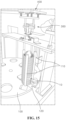
- the mesh net lifting unit 600 serves to move the multi-stacked mesh nets 10 upwards and downwards and is fixedly located on the frame 50, while being spaced apart from the first table 100 and the upper table 200.
- the upper table 200 has a height sensor 230 adapted to sense a height of the mesh net 10 exposed from the mesh net through hole 210, and the mesh net lifting unit 600 is adapted to move the stacked mesh nets 10 to an appropriate set position according to the sensed value of the height sensor 230, thereby adjusting the arranged positions of the stacked mesh nets 10.
- the position (height) of the topmost mesh net 10 among the multi-stacked mesh nets 10 is controlled by means of the mesh net lifting unit 600 to allow the topmost mesh net 10 to be stably gripped by means of the gripping unit 300 moving downwards through the elevating unit 400.
- a controller (not shown) receives the sensed value of the height sensor 230 and operates the mesh net lifting unit 600, based on the received sensed value, to allow the topmost mesh net 10 to be adjusted in position.
- the height sensor 230 includes a light receiver and a light emitter and irradiates light toward the mesh net 10, detects the reflected light on the mesh net 10, and senses the height of the mesh net 10.
- the mesh net lifting unit 600 includes a lifting driver 610, a first lifting block 620, a second lifting block 630, and elastic members 640.
- the lifting driver 610 serves to reciprocate the first lifting block 620 and the second lifting block 630 in upward and downward directions and has various structures such as a ball screw, a gear rack, and the like, and according to the embodiment of the present disclosure, the lifting driver 610 is in the form of a ball and screw unit consisting of a ball screw and a moving block 611 moving along the ball screw, while being located in a height direction corresponding to the height direction of the multi-stacked mesh nets 10.
- the first lifting block 620 reciprocates along the lifting driver 610.
- the first lifting block 620 is connected to the moving block 611 so that the first lifting block 620 and the moving block 611 move upwards and downwards together.
- the second lifting block 630 serves to support the underside of the bottommost mesh net 10 among the multi-stacked mesh nets 10 and is connected to the first lifting block 620 by means of linear bushes and guide bars.
- the elastic members 640 are placed between the first lifting block 620 and the second lifting block 630 to allow the second lifting block 630 to be elastically close to or separated from the first lifting block 620 fixedly connected to the moving block 611.
- the second lifting block 630 serves to elastically support the undersides of the multi-stacked mesh nets 10 seated on top thereof, so that if the gripping unit 300 moves down towards the topmost mesh net 10 by means of the operation of the elevating unit 400 and provides a given downward pressurizing force to the topmost mesh net 10, the second lifting block 630 prevents the neighboring mesh nets 10 in upward and downward directions from being stacked on top of one another under such a pressurizing force.
- the pressurizing force generated when the gripping unit 300 pressurizes the topmost mesh net 10 downwards causes the neighboring mesh nets 10 in upward and downward directions to be stacked on top of one another, but if the second lifting block 630 is fixed in a state of being not movable elastically, the pressurizing force is not offset so that it is transmitted to the stacked mesh nets 10, thereby undesirably increasing a probability that the mesh nets 10 are forcedly stacked on top of one another.
- the second lifting block 630 moves downwards by means of the same pressurizing force and elastically supports the multi-stacked mesh nets 10, thereby preventing the mesh nets 10 from being strongly stacked on top of one another due to the force applied from the gripping unit 300.
- the same/similar structure as mentioned above may be located between the elevating unit 400 and the gripping unit 300 to prevent the neighboring mesh nets 10 in the upward and downward directions from being unexpectedly stacked on top of one another by means of the downward pressurizing force against the topmost mesh net 10, which will be discussed later.
- the first lifting block 620 and the second lifting block 630 pass through the incised groove 120 and move upwards and downwards.
- the topmost mesh net 10 becomes low in height, and based on the sensed value of the height sensor 230, in this case, the lifting driver 610 lifts the first lifting block 620 and the second lifting block 630 upwards by the height lowered by one separated mesh net 10.
- the first lifting block 620 and the second lifting block 630 pass through the incised groove 120 of the first table 100 in an upward direction and lifts the multi-stacked mesh nets 10 upwards.
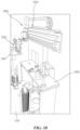
- the gripping unit 300 serves to grip the mesh net 10 exposed from the mesh net through hole 210, that is, the topmost mesh net 10 among the multi-stacked mesh nets 10.
- the gripping unit 300 includes a chuck base 310, gripping jaws 320, and gripping actuators 330.
- the chuck base 310 is connected to the elevating unit 400 in such a way as to move upwards and downwards by means of the operation of the elevating unit 400.
- the gripping jaws 320 serve to actually grip the mesh net 10 and are coupled to the chuck base 310 in such a way as to be spaced apart from one another along the circumferential direction of the mesh net body 11. Accordingly, the gripping jaws 320 move to the mesh net body 11 and grip the mesh net body 11.
- the gripping actuators 330 are located on the chuck base 310 in such a way as to allow the gripping jaws 320 to be close to or spaced apart from the mesh net body 11, and they are in the form of pneumatic cylinders.
- gripping blocks 331 are connected to the end portions of the pneumatic cylinders, and the gripping jaws 320 are fixed to the gripping blocks 331 by means of screws or the like.
- teeth are formed on one side of each gripping jaw 320 in such a way as to allow given portions thereof to be inserted into the meshes of the mesh net 10 and grip the mesh net 10, and the gripping jaw 320 has two screw-coupling holes 321.
- One of the two screw-coupling holes 321 is arch-shaped.
- a screw is coupled to the other screw-coupling hole 321 to allow the gripping jaw 320 to be fixed to the corresponding gripping block 331.
- one screw is coupled to allow the gripping jaw 320 to be temporarily fixed to the corresponding gripping block 331, and the gripping jaw 320 rotates around the coupled screw to find an optimal angle for gripping the mesh net 10 more efficiently.
- a screw is fastened to the arch-shaped screw-coupling hole, thereby allowing the gripping jaw 320 to be completely fixed to the corresponding gripping block 331.
- the elevating unit 400 moves the gripping unit 300 upwards and downwards and includes an elevating actuator 410 and an elevating plate 420 connected to the elevating actuator 410 in such a way to move upwards and downwards, while locating the chuck base 310 thereunder.
- the shuttle unit 500 transfers the gripping unit 300 and the elevating unit 400 between the first table 100 and the second table 700 and has various structures such as a linear motion (LM) guide unit, a ball screw unit, and the like that are capable of linearly reciprocating a shuttle transfer block 510.
- LM linear motion
- the elevating actuator 410 is coupled to the shuttle transfer block 510 and reciprocates between the first table 100 and the second table 700, together with the shuttle transfer block 510.
- the chuck base 310 has a pusher 311 adapted to pressurize the mesh net body 11 downwards by means of the operation of the elevating unit 400. That is, if the elevating unit 400 operates to allow the chuck base 310 to move down towards the topmost mesh net 10 among the multi-stacked mesh nets 10, the pusher 311 elastically pressurizes the mesh net 10, and under such a pressurizing state, the gripping actuators 330 operate to allow the gripping jaws 320 to become close to the mesh net body 11 and grip the mesh net body 11.
- the pusher 311 has curved surfaces formed on the inner surface thereof in such a way as to correspond to the convex shape of the mesh net body 11. As a result, if the pusher 311 pressurizes the concave upper portion of the mesh net body 11, it prevents the mesh net body 11 from being deformed in shape.
- elastic members 312 are located between the chuck base 310 and the elevating plate 420 to allow the pusher 311 to elastically pressurize the mesh net body 11.
- the chuck base 310 is connected to the elevating plate 420 by means of linear bushes and guide bars.
- the elastic members 312 are placed between the chuck base 310 and the elevating plate 420 to elastically support the chuck base 310 so that when the gripping unit 300 moves downwards through the operation of the elevating unit 400 to allow the pusher 311 to pressurize the concave upper portion of the mesh net body 11, the chuck base 310 becomes close to the elevating plate 420, without being fixed.
- the gripping unit 300 After the mesh net 10 has been gripped by the gripping unit 300, if the gripping unit 300 moves upwards by means of the elevating unit 400, the chuck base 310 moves in a direction spaced apart from the elevating plate 420 by means of the restoring forces of the elastic members 312 and is returned to its original position.
- the elastic members 312 elastically support the pusher 311 by means of the elastic forces generated therefrom, so that when the pusher 311 pressurizes the mesh net body 11, the elastic members 312 serve to offset the pressurizing force of the pusher 311 to an extent in the same manner as the above-mentioned elastic members 640, thereby preventing the neighboring mesh nets 10 in upward and downward directions from being forcedly stacked on top of one another due to the pressurizing force of the pusher 311.
- the pressurizing force generated when the pusher 311 pressurizes the topmost mesh net 10 downwards causes the neighboring mesh nets 10 in upward and downward directions to be stacked on top of one another, but if the chuck base 310 and the pusher 311 are fixed in states of being not movable elastically, the pressurizing force is not offset so that it is transmitted to the stacked mesh nets 10 in the upward and downward directions, thereby undesirably increasing a probability that the mesh nets 10 are forcedly stacked on top of one another.
- the upper table 200 has a gripping sensor 240 for sensing whether the gripping unit 300 moves up to a given upward position after it has gripped the mesh net 10 normally.
- the gripping sensor 240 includes a light receiver and a light emitter and irradiates light toward the mesh net 10, detects the reflected light on the mesh net 10, and senses whether the mesh net 10 is normally gripped.
- the controller moves the elevating unit 400 downwards again, operates the gripping unit 300, and allows the mesh net 10 to be gripped again.
- the mesh net supply apparatus further includes the second table 700, a stacking sensor 250, and a collection container 800.
- the second table 700 is located at a position spaced apart from the first table 100 and allows the mesh net 10 transferred through the shuttle unit 500 to be seated on top thereof.
- the second table 700 has the same circular plate as a turn table rotating by a driving part such as a driving motor, which is the same as the first table 10.
- a driving part such as a driving motor
- the plurality of mesh nets 10 are seated on top of the second table 700, and in this case, four positions for seating the mesh nets 10 are spaced apart from one another along the circumferential direction of the second table 700.
- the second table 700 rotates by 90°, and if four mesh nets 10 are finally seated on top of the second table 700, they are gripped at a time by means of a separate gripper (not shown), move to the casting mold, and are thus mounted onto the casting mold.
- the upper table 200 has the stacking sensor 250 adapted to sense whether at least two or more stacked mesh nets 10 are gripped by the gripping unit 300.
- the stacking sensor 250 as a type of vision sensor includes a light receiver and a light emitter and irradiates light toward the mesh net 10 gripped by the gripping unit 300, detects the reflected light on the mesh net 10, and senses whether the mesh nets 10 are stacked on top of each other.
- the stacking sensor 250 can sense whether the two mesh nets 10 are stacked on top of each other from the differences between the properties of the light reflected on one mesh net 10 and the properties of the light reflected on two stacked mesh nets 10.
- the collection container 800 is located between the first table 100 and the second table 700, and if it is sensed that at least two mesh nets 10 are stacked on top of each other through the stacking sensor 250, the collection container 800 serves to separate and collect the two stacked mesh nets 10.
- the controller If it is sensed that at least two mesh nets 10 are stacked on top of each other through the stacking sensor 250, the controller operates the shuttle unit 500 to allow the mesh nets 10 gripped to be stopped above the collection container 800 on a path moving to the second table 700, and next, the controller controls the gripping unit 300 to allow the gripped states of the mesh nets 10 to be released so that the stacked mesh nets 10 fall down in the collection container 800.
- the mesh net supply apparatus is configured to allow the flange of the topmost mesh net to be locked onto the plurality of separation plates and elastically bent, at the moment when the topmost mesh net is lifted upwards, in the process of lifting the topmost mesh net among the multi-stacked mesh nets upwards and sequentially supplying the mesh nets, so that even if the mesh nets are stacked on top of each other in a process of passing through the plurality of separation plates, they are separated from each other, thereby reliably supplying not two or more stacked mesh net, but only one mesh net.
- the mesh net supply apparatus is configured to allow the elastic members to be placed between the first lifting block and the second lifting block of the mesh net lifting unit and between the chuck base and the elevating plate, respectively, so that when top of the multi-stacked mesh nets is pressurized downwards, the elastic members can offset the pressurizing force to an extent, thereby preventing the neighboring mesh nets in upward and downward directions from being stacked on top of one another under the pressurizing force of the pusher.
- the pressurizing force generated when the gripping unit 300 pressurizes the topmost mesh net 10 downwards causes the neighboring mesh nets in upward and downward directions to be stacked on top of each other, but if the second lifting block 630 is fixed in a state of being not movable elastically, the pressurizing force is not offset so that it is transmitted to the stacked mesh nets 10 to increase a probability that the mesh nets 10 to be forcedly stacked on top of one another.
Landscapes
- Engineering & Computer Science (AREA)
- Mechanical Engineering (AREA)
- De-Stacking Of Articles (AREA)
Applications Claiming Priority (1)
| Application Number | Priority Date | Filing Date | Title |
|---|---|---|---|
| KR1020230171942A KR20250084305A (ko) | 2023-12-01 | 2023-12-01 | 메쉬망 공급장치 |
Publications (1)
| Publication Number | Publication Date |
|---|---|
| EP4563265A1 true EP4563265A1 (fr) | 2025-06-04 |
Family
ID=93648659
Family Applications (1)
| Application Number | Title | Priority Date | Filing Date |
|---|---|---|---|
| EP24214491.3A Pending EP4563265A1 (fr) | 2023-12-01 | 2024-11-21 | Appareil d'alimentation en filet maillé |
Country Status (3)
| Country | Link |
|---|---|
| US (1) | US20250178082A1 (fr) |
| EP (1) | EP4563265A1 (fr) |
| KR (1) | KR20250084305A (fr) |
Citations (6)
| Publication number | Priority date | Publication date | Assignee | Title |
|---|---|---|---|---|
| US5092734A (en) * | 1989-05-19 | 1992-03-03 | Mazda Motor Corporation | Filter feeder |
| JPH04111946A (ja) * | 1990-08-30 | 1992-04-13 | Honda Motor Co Ltd | 鋳造用金属フィルタの供給装置 |
| KR101932630B1 (ko) * | 2017-04-17 | 2018-12-27 | (주)알룩스메뉴펙처링 | 알루미늄 주조용 철망필터 공급장치 |
| JP6985199B2 (ja) * | 2018-03-29 | 2021-12-22 | 株式会社五十鈴製作所 | 金網把持装置およびこれを備える金網セット装置 |
| JP7035841B2 (ja) * | 2018-06-20 | 2022-03-15 | トヨタ自動車株式会社 | 金網供給装置 |
| KR20220159822A (ko) | 2021-05-26 | 2022-12-05 | 주식회사 대유글로벌 | 세라믹 컵 |
-
2023
- 2023-12-01 KR KR1020230171942A patent/KR20250084305A/ko active Pending
-
2024
- 2024-11-21 EP EP24214491.3A patent/EP4563265A1/fr active Pending
- 2024-11-26 US US18/960,812 patent/US20250178082A1/en active Pending
Patent Citations (6)
| Publication number | Priority date | Publication date | Assignee | Title |
|---|---|---|---|---|
| US5092734A (en) * | 1989-05-19 | 1992-03-03 | Mazda Motor Corporation | Filter feeder |
| JPH04111946A (ja) * | 1990-08-30 | 1992-04-13 | Honda Motor Co Ltd | 鋳造用金属フィルタの供給装置 |
| KR101932630B1 (ko) * | 2017-04-17 | 2018-12-27 | (주)알룩스메뉴펙처링 | 알루미늄 주조용 철망필터 공급장치 |
| JP6985199B2 (ja) * | 2018-03-29 | 2021-12-22 | 株式会社五十鈴製作所 | 金網把持装置およびこれを備える金網セット装置 |
| JP7035841B2 (ja) * | 2018-06-20 | 2022-03-15 | トヨタ自動車株式会社 | 金網供給装置 |
| KR20220159822A (ko) | 2021-05-26 | 2022-12-05 | 주식회사 대유글로벌 | 세라믹 컵 |
Also Published As
| Publication number | Publication date |
|---|---|
| US20250178082A1 (en) | 2025-06-05 |
| KR20250084305A (ko) | 2025-06-11 |
Similar Documents
| Publication | Publication Date | Title |
|---|---|---|
| JP7130854B2 (ja) | 残留ワークからワーク部分を取り出す方法および装置 | |
| US5102293A (en) | Unstacking apparatus for removing a partial stack from a stack of sheets | |
| EP0862957B1 (fr) | Dispositif pour le chargement et le déchargement des tôles | |
| US4197772A (en) | Automatic feeding apparatus for punch press | |
| US20030123962A1 (en) | Method and device for de-palletizing stacks of blanks | |
| EP0780172A2 (fr) | Procédé et dispositif pour le chargement et le déchargement automatique d'une pièce de tÔle | |
| EP0190754B1 (fr) | Dispositif semi-rigide de séparation de tôles et procédé de séparation | |
| CN111908240B (zh) | 具有配备震动板的叠堆设备的印刷机 | |
| EP4563265A1 (fr) | Appareil d'alimentation en filet maillé | |
| CN111908241A (zh) | 具有配备震动板的叠堆设备的印刷机 | |
| CN116477342B (zh) | 丝网印刷设备及丝网印刷方法 | |
| GB2100708A (en) | A materials-handling machine | |
| CN117585401B (zh) | 一种取料装置及取料方法 | |
| US5253505A (en) | Press with a drawing apparatus | |
| US4561817A (en) | Retort crate loader and unloader | |
| JP3508219B2 (ja) | 部品供給装置 | |
| JPH04187333A (ja) | 板材加工装置の分離板材取出し装置 | |
| CN214988651U (zh) | 一种气缸切换步进抬升供应料仓机构 | |
| US4436470A (en) | Retort crate loader and unloader | |
| JP3429617B2 (ja) | 湾曲ガラス板の成形不良部検出方法および成形支持枠 | |
| DE19526595C2 (de) | Bogenanleger | |
| CN121339705B (zh) | 一种激光咬花机 | |
| US4109802A (en) | Depalletizing apparatus | |
| JPH0450996Y2 (fr) | ||
| SU1156923A1 (ru) | Устройство дл подачи заготовок из стопы в зону обработки |
Legal Events
| Date | Code | Title | Description |
|---|---|---|---|
| PUAI | Public reference made under article 153(3) epc to a published international application that has entered the european phase |
Free format text: ORIGINAL CODE: 0009012 |
|
| STAA | Information on the status of an ep patent application or granted ep patent |
Free format text: STATUS: REQUEST FOR EXAMINATION WAS MADE |
|
| 17P | Request for examination filed |
Effective date: 20241121 |
|
| AK | Designated contracting states |
Kind code of ref document: A1 Designated state(s): AL AT BE BG CH CY CZ DE DK EE ES FI FR GB GR HR HU IE IS IT LI LT LU LV MC ME MK MT NL NO PL PT RO RS SE SI SK SM TR |