EP4566935A1 - Verfahren und system zur durchführung geophysikalischer, physikalisch-chemischer, bildgebungs- und profilierungsmessungen durch eine autonome unterwasserfahrzeugbildung mit überlagerungsbestimmungsalgorithmen - Google Patents
Verfahren und system zur durchführung geophysikalischer, physikalisch-chemischer, bildgebungs- und profilierungsmessungen durch eine autonome unterwasserfahrzeugbildung mit überlagerungsbestimmungsalgorithmen Download PDFInfo
- Publication number
- EP4566935A1 EP4566935A1 EP23213171.4A EP23213171A EP4566935A1 EP 4566935 A1 EP4566935 A1 EP 4566935A1 EP 23213171 A EP23213171 A EP 23213171A EP 4566935 A1 EP4566935 A1 EP 4566935A1
- Authority
- EP
- European Patent Office
- Prior art keywords
- buoys
- auv
- auvs
- formation
- underwater
- Prior art date
- Legal status (The legal status is an assumption and is not a legal conclusion. Google has not performed a legal analysis and makes no representation as to the accuracy of the status listed.)
- Pending
Links
Images
Classifications
-
- G—PHYSICS
- G01—MEASURING; TESTING
- G01V—GEOPHYSICS; GRAVITATIONAL MEASUREMENTS; DETECTING MASSES OR OBJECTS; TAGS
- G01V3/00—Electric or magnetic prospecting or detecting; Measuring magnetic field characteristics of the earth, e.g. declination, deviation
- G01V3/15—Electric or magnetic prospecting or detecting; Measuring magnetic field characteristics of the earth, e.g. declination, deviation specially adapted for use during transport, e.g. by a person, vehicle or boat
-
- G—PHYSICS
- G01—MEASURING; TESTING
- G01S—RADIO DIRECTION-FINDING; RADIO NAVIGATION; DETERMINING DISTANCE OR VELOCITY BY USE OF RADIO WAVES; LOCATING OR PRESENCE-DETECTING BY USE OF THE REFLECTION OR RERADIATION OF RADIO WAVES; ANALOGOUS ARRANGEMENTS USING OTHER WAVES
- G01S1/00—Beacons or beacon systems transmitting signals having a characteristic or characteristics capable of being detected by non-directional receivers and defining directions, positions, or position lines fixed relatively to the beacon transmitters; Receivers co-operating therewith
- G01S1/72—Beacons or beacon systems transmitting signals having a characteristic or characteristics capable of being detected by non-directional receivers and defining directions, positions, or position lines fixed relatively to the beacon transmitters; Receivers co-operating therewith using ultrasonic, sonic or infrasonic waves
-
- G—PHYSICS
- G01—MEASURING; TESTING
- G01S—RADIO DIRECTION-FINDING; RADIO NAVIGATION; DETERMINING DISTANCE OR VELOCITY BY USE OF RADIO WAVES; LOCATING OR PRESENCE-DETECTING BY USE OF THE REFLECTION OR RERADIATION OF RADIO WAVES; ANALOGOUS ARRANGEMENTS USING OTHER WAVES
- G01S15/00—Systems using the reflection or reradiation of acoustic waves, e.g. sonar systems
- G01S15/02—Systems using the reflection or reradiation of acoustic waves, e.g. sonar systems using reflection of acoustic waves
- G01S15/06—Systems determining the position data of a target
- G01S15/08—Systems for measuring distance only
-
- G—PHYSICS
- G01—MEASURING; TESTING
- G01S—RADIO DIRECTION-FINDING; RADIO NAVIGATION; DETERMINING DISTANCE OR VELOCITY BY USE OF RADIO WAVES; LOCATING OR PRESENCE-DETECTING BY USE OF THE REFLECTION OR RERADIATION OF RADIO WAVES; ANALOGOUS ARRANGEMENTS USING OTHER WAVES
- G01S15/00—Systems using the reflection or reradiation of acoustic waves, e.g. sonar systems
- G01S15/74—Systems using reradiation of acoustic waves, e.g. IFF, i.e. identification of friend or foe
-
- G—PHYSICS
- G01—MEASURING; TESTING
- G01S—RADIO DIRECTION-FINDING; RADIO NAVIGATION; DETERMINING DISTANCE OR VELOCITY BY USE OF RADIO WAVES; LOCATING OR PRESENCE-DETECTING BY USE OF THE REFLECTION OR RERADIATION OF RADIO WAVES; ANALOGOUS ARRANGEMENTS USING OTHER WAVES
- G01S15/00—Systems using the reflection or reradiation of acoustic waves, e.g. sonar systems
- G01S15/86—Combinations of sonar systems with lidar systems; Combinations of sonar systems with systems not using wave reflection
-
- G—PHYSICS
- G01—MEASURING; TESTING
- G01S—RADIO DIRECTION-FINDING; RADIO NAVIGATION; DETERMINING DISTANCE OR VELOCITY BY USE OF RADIO WAVES; LOCATING OR PRESENCE-DETECTING BY USE OF THE REFLECTION OR RERADIATION OF RADIO WAVES; ANALOGOUS ARRANGEMENTS USING OTHER WAVES
- G01S15/00—Systems using the reflection or reradiation of acoustic waves, e.g. sonar systems
- G01S15/87—Combinations of sonar systems
- G01S15/874—Combination of several spaced transponders or reflectors of known location for determining the position of a receiver
-
- G—PHYSICS
- G01—MEASURING; TESTING
- G01S—RADIO DIRECTION-FINDING; RADIO NAVIGATION; DETERMINING DISTANCE OR VELOCITY BY USE OF RADIO WAVES; LOCATING OR PRESENCE-DETECTING BY USE OF THE REFLECTION OR RERADIATION OF RADIO WAVES; ANALOGOUS ARRANGEMENTS USING OTHER WAVES
- G01S15/00—Systems using the reflection or reradiation of acoustic waves, e.g. sonar systems
- G01S15/87—Combinations of sonar systems
- G01S15/876—Combination of several spaced transmitters or receivers of known location for determining the position of a transponder or a reflector
-
- G—PHYSICS
- G01—MEASURING; TESTING
- G01S—RADIO DIRECTION-FINDING; RADIO NAVIGATION; DETERMINING DISTANCE OR VELOCITY BY USE OF RADIO WAVES; LOCATING OR PRESENCE-DETECTING BY USE OF THE REFLECTION OR RERADIATION OF RADIO WAVES; ANALOGOUS ARRANGEMENTS USING OTHER WAVES
- G01S15/00—Systems using the reflection or reradiation of acoustic waves, e.g. sonar systems
- G01S15/88—Sonar systems specially adapted for specific applications
- G01S15/89—Sonar systems specially adapted for specific applications for mapping or imaging
-
- G—PHYSICS
- G01—MEASURING; TESTING
- G01S—RADIO DIRECTION-FINDING; RADIO NAVIGATION; DETERMINING DISTANCE OR VELOCITY BY USE OF RADIO WAVES; LOCATING OR PRESENCE-DETECTING BY USE OF THE REFLECTION OR RERADIATION OF RADIO WAVES; ANALOGOUS ARRANGEMENTS USING OTHER WAVES
- G01S5/00—Position-fixing by co-ordinating two or more direction or position line determinations; Position-fixing by co-ordinating two or more distance determinations
- G01S5/18—Position-fixing by co-ordinating two or more direction or position line determinations; Position-fixing by co-ordinating two or more distance determinations using ultrasonic, sonic or infrasonic waves
-
- G—PHYSICS
- G01—MEASURING; TESTING
- G01V—GEOPHYSICS; GRAVITATIONAL MEASUREMENTS; DETECTING MASSES OR OBJECTS; TAGS
- G01V3/00—Electric or magnetic prospecting or detecting; Measuring magnetic field characteristics of the earth, e.g. declination, deviation
- G01V3/08—Electric or magnetic prospecting or detecting; Measuring magnetic field characteristics of the earth, e.g. declination, deviation operating with magnetic or electric fields produced or modified by objects or geological structures or by detecting devices
- G01V3/081—Electric or magnetic prospecting or detecting; Measuring magnetic field characteristics of the earth, e.g. declination, deviation operating with magnetic or electric fields produced or modified by objects or geological structures or by detecting devices the magnetic field is produced by the objects or geological structures
-
- B—PERFORMING OPERATIONS; TRANSPORTING
- B63—SHIPS OR OTHER WATERBORNE VESSELS; RELATED EQUIPMENT
- B63G—OFFENSIVE OR DEFENSIVE ARRANGEMENTS ON VESSELS; MINE-LAYING; MINE-SWEEPING; SUBMARINES; AIRCRAFT CARRIERS
- B63G8/00—Underwater vessels, e.g. submarines; Equipment specially adapted therefor
- B63G8/39—Arrangements of sonic watch equipment, e.g. low-frequency, sonar
-
- G—PHYSICS
- G01—MEASURING; TESTING
- G01S—RADIO DIRECTION-FINDING; RADIO NAVIGATION; DETERMINING DISTANCE OR VELOCITY BY USE OF RADIO WAVES; LOCATING OR PRESENCE-DETECTING BY USE OF THE REFLECTION OR RERADIATION OF RADIO WAVES; ANALOGOUS ARRANGEMENTS USING OTHER WAVES
- G01S2205/00—Position-fixing by co-ordinating two or more direction or position line determinations; Position-fixing by co-ordinating two or more distance determinations
- G01S2205/01—Position-fixing by co-ordinating two or more direction or position line determinations; Position-fixing by co-ordinating two or more distance determinations specially adapted for specific applications
- G01S2205/04—Nautical
Definitions
- the subject of the invention is a method and system for conducting geophysical, physicochemical, imaging and profiling measurements with the use of autonomous underwater vehicle formation using superposition determination algorithms in order to increase the quality and efficiency of the measurements.
- Underwater measurements such as geophysical surveys using multi-beam sonars, side-scan sonars, magnetometers, measurements of physicochemical properties of water reservoirs, bottom contour imaging and searching for objects lying on the bottom or buried under its surface, pose a challenge mainly in terms of determining the exact position of the measurement as well as improving its cost efficiency.
- the aquatic environment poses a challenge in determining the exact position of objects under water, both searched objects such as UXO and underwater ROV and AUV vehicles due to the lack of a GPS signal under the water surface, variable speed of propagation of acoustic waves in water, refraction of acoustic waves, occurrence "shadow zones", reflections of acoustic waves in the vicinity of hydrotechnical infrastructure and in shallow waters, lack of fast underwater communication, interference of devices with each other.
- Another challenge in the area of performing geophysical and physicochemical measurements, imaging and profiling of water bodies are changing weather conditions and high costs of purchasing, renting and mobilizing units and sensors used for research, which is why cost effectiveness by increasing the speed of research is very important.
- the limitation is the frequency of the measuring device, a significant part of the measurements are performed by hydroacoustic measurements and the measurement beam must travel from the sensor to the object or bottom and return, which determines the measurement speed.
- the only way to increase the efficiency of measurements is to increase the width of the measurement lane.
- the invention in the form of a method and system for performing geophysical, physicochemical, imaging and profiling measurements using formations of autonomous underwater vehicles using algorithms for determining superposition will allow to determine such trajectories of each AUV within the formation to achieve the designated mission goal and to maximize the width of the measurement LANE, which will directly improve the cost effectiveness of conducted research.
- Geophysical and physicochemical measurements, bottom imaging and profiling are an essential element of the investment process as part of offshore projects, port expansion, dredging of rivers and reservoirs, exploration, environmental monitoring, and monitoring of critical infrastructure.
- the most common methods for determining the position of underwater vehicles using acoustic waves for location include the Ultra Short Base Line (USBL) or Super Short Base Line (SSBL).
- the localization system includes, in the surface part: a compass, a tilt sensor, at least one GPS receiver and a hydrolocation head mounted under the water surface called a Transceiver, and an underwater acoustic module called a Transponder or Beacon mounted on an ROV or AUV underwater vehicle.
- the transceiver head consists of a system of min. 3 hydrophones at a baseline distance typically 10 cm.
- the position of the underwater vehicle is determined by calculating the distance and angle at which the acoustic wave reaches from the Transponder installed on the underwater vehicle to the Transceiver installed on the surface unit.
- the distance between the Transceiver and the Transponder is calculated according to the speed of sound propagation in a given water medium and the time required for the sound wave to travel from the Transceiver to the Transponder.
- the acoustic cycle is as follows, the signal is transmitted from the Transceiver to the Transponder and then the Transponder responds with another acoustic signal to the Transceiver.
- USBL location system is very popular due to its lower costs compared to alternative solutions and procedurally easier calibration, but it has a number of disadvantages: (1) the occurrence of angular error and the increase in the angular position error with increasing the distance between the Transceiver and the Transponder, the so-called slant range; (2) the system requires time-consuming calibration of the direction (Heading) and distance calculated based on the speed of sound (Range); (3) is susceptible to warhead roll errors due to the rigid mechanical connection to the surface vessel; (4) high sensitivity to disturbances related to reflected waves, interference and the occurrence of sound wave refraction, which result in the so-called shadow zones.
- an IMU Inertial Motion Unit tilt sensor
- the Long Base Line LBL solution is known.
- hydrolocation buoys are used, which measure the distance of the underwater vehicle to a minimum of three hydrolocation buoys. Determining the underwater position is often supplemented with data from the depth sensor of the underwater vehicle.
- the position of the underwater vehicle is determined by the following acoustic cycle: (1) the transponder on the vehicle sends an acoustic signal which is received by the long baseline transponders; (2) the transponders respond and the acoustic feedback is received by the vehicle's transponder; (3) measuring the time needed for the acoustic signal to cover the distance between the vehicle and the LBL hydrolocation buoys allows the position of the transponder on the vehicle to be calculated using triangulation or position search algorithms.
- the geometry of the hydrolocation buoy system and the calculated position of the underwater vehicle can be transformed into a coordinate system with geographical references.
- the hydrolocation system based on a long baseline is used when accurate determination of the underwater position of underwater vehicles is required.
- the disadvantages of the long LBL baseline system include: (1) the time-consuming process of setting up the buoys at the bottom of the reservoir and retrieving them after the measurements are completed; (2) the time-consuming process of determining the geolocation coordinates of individual buoys, which, similarly to USBL calibration, requires collecting a cloud of points in order to average the position by swimming around the submerged buoys; (4) high system costs; (5) a minimum number of 3 hydrolocation buoys to determine the position of the transponder installed on the underwater vehicle.
- the essence of the invention The system for performing geophysical, physicochemical measurements, imaging and profiling with the formation of autonomous underwater vehicles using the algorithms for determining superposition according to the invention solves the shortcomings of the above solutions in an unprecedented and non-obvious way.
- the system for performing geophysical, physicochemical measurements, imaging and profiling with the formation of autonomous underwater vehicles using the algorithms for determining superposition according to the invention is characterized by the following features:
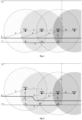
- the following are marked: the water line (5), the bottom line (6), the target depth of the reservoir to which objects with a defined minimum magnetic field intensity are searched (7), usually this is the target
- target depth (4) measurement range of magnetometers installed on AUVs (2) and the distance to the bottom at which the AUV is to swim (3) allows for the calculation of the optimal trajectory for each AUV in such a way that through circles with radius (2), a part common to at least 2 vehicles is determined.
- the exact position of the sought object can be determined using a horizontal gradient. Knowing the magnetic field strength of the sought object recorded by each magnetometer, an intersection point is determined for the condition when both magnetometers have the same magnetic field strength value as a function of the distance of the object to the magnetometer.
- Fig. 1 shows the formation system of AUVs in the case of a flat bottom of a reservoir, then the measurement belt, in the area of which it is possible to determine the mass and the exact position of the identified ferromagnetic object, corresponds to the part common to all three AUVs (9).
- the coverage margin (8) referred to as Overlapping in geophysical studies is taken into account.
- the measurement method according to the invention allows to calculate the maximum horizontal distance between underwater autonomous vehicles (1) and, taking into account the condition that the vehicles cannot exceed the specified measurement speed, to obtain the most cost-effective formation of AUVs.
- Section (10) is the distance between the path of the outermost vehicle in the formation (according to the AUV3 example) and the path of the outermost vehicle AUV1' during the next measurement strip.
- Fig. 2 shows a case when the depth in the measurement area varies during measurements.
- the difference between the depths of the reservoir (11) requires that the formation, when performing magnetometric measurements, changes its layout in such a way that the AUV1 vehicle maintains the set distance to the bottom (3), new circles with maximum range and parts common to all sensors on AUV 1 vehicles are designated to AUV 3.
- the distance (1) between AUV 1 and AUV 2 is the maximum distance with the depth difference (11), in this case, the coverage margin (8) in Fig. 1 takes the value zero and corresponds to the intersection of circles with radius (2) plotted from the position of vehicle AUV1 and vehicle AUV 2 and is located in Fig. 2 at point (12).
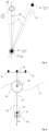
- the subject of the invention in the form of self-calibration of hydrolocation buoys is shown in Fig. 3 .
- the USBL1 hydrolocation buoy consisting of the GPS Receiver 1 (13) and the underwater Transceiver USBL 1 (14) determines the direction in which the hydrolocation buoy 2 (15) is located based on geographical coordinates GPS 1 and GPS 2 receivers. Hydrolocation buoys 1 and 2 have a wireless communication link.
- the USBL 1 Transceiver (14) measures the distance and direction according to the USBL 2 Transceiver (16). Due to the angular error of the measurements of the USBL heads (17), it is necessary to perform several measurements of the angle of arrival of the signal from the Transceiver (16) in order to determine the correct angular error (18).
- the second parameter subject to calibration is the speed of sound propagation in water, which is corrected after taking into account the known difference in distance (19) between the GPS receivers of buoys 1 and 2 and the distance calculated between Transceivers 1 and 2.
- the USBL 2 hydrolocation buoy self-calibrates according to the Receiver. GPS 1 and USBL 1 Transceiver.
- Fig. 4 shows the construction of a hydro location buoy.
- the hydro location buoy consists of a USBL transceiver (21) with an internal IMU inertial sensor (22), a buoyancy part that keeps the buoy on the surface (20), a controller with a GPS receiver, a wireless communication module, an atomic clock (24), and a satellite compass (25).
- the hydro location buoy has positive buoyancy and stays on the water surface (27). Due to the rigid connection of the buoyancy part (20) with the USBL transceiver (21) and the distance between the center of buoyancy CB and the center of gravity CG, the buoy has a righting moment ensuring a stable vertical position of the buoy.
Landscapes
- Engineering & Computer Science (AREA)
- Remote Sensing (AREA)
- Radar, Positioning & Navigation (AREA)
- Physics & Mathematics (AREA)
- General Physics & Mathematics (AREA)
- Computer Networks & Wireless Communication (AREA)
- Life Sciences & Earth Sciences (AREA)
- Acoustics & Sound (AREA)
- Environmental & Geological Engineering (AREA)
- Geology (AREA)
- General Life Sciences & Earth Sciences (AREA)
- Geophysics (AREA)
- Electromagnetism (AREA)
- Measurement Of Velocity Or Position Using Acoustic Or Ultrasonic Waves (AREA)
Priority Applications (1)
| Application Number | Priority Date | Filing Date | Title |
|---|---|---|---|
| EP23213171.4A EP4566935A1 (de) | 2023-11-29 | 2023-11-29 | Verfahren und system zur durchführung geophysikalischer, physikalisch-chemischer, bildgebungs- und profilierungsmessungen durch eine autonome unterwasserfahrzeugbildung mit überlagerungsbestimmungsalgorithmen |
Applications Claiming Priority (1)
| Application Number | Priority Date | Filing Date | Title |
|---|---|---|---|
| EP23213171.4A EP4566935A1 (de) | 2023-11-29 | 2023-11-29 | Verfahren und system zur durchführung geophysikalischer, physikalisch-chemischer, bildgebungs- und profilierungsmessungen durch eine autonome unterwasserfahrzeugbildung mit überlagerungsbestimmungsalgorithmen |
Publications (1)
| Publication Number | Publication Date |
|---|---|
| EP4566935A1 true EP4566935A1 (de) | 2025-06-11 |
Family
ID=91621165
Family Applications (1)
| Application Number | Title | Priority Date | Filing Date |
|---|---|---|---|
| EP23213171.4A Pending EP4566935A1 (de) | 2023-11-29 | 2023-11-29 | Verfahren und system zur durchführung geophysikalischer, physikalisch-chemischer, bildgebungs- und profilierungsmessungen durch eine autonome unterwasserfahrzeugbildung mit überlagerungsbestimmungsalgorithmen |
Country Status (1)
| Country | Link |
|---|---|
| EP (1) | EP4566935A1 (de) |
Citations (2)
| Publication number | Priority date | Publication date | Assignee | Title |
|---|---|---|---|---|
| JP2023123041A (ja) * | 2022-02-24 | 2023-09-05 | 株式会社Ihi | 測位装置 |
| WO2023194803A1 (en) * | 2022-04-05 | 2023-10-12 | Cellula Robotics, Ltd. | Underwater vehicles for vessel characterization |
-
2023
- 2023-11-29 EP EP23213171.4A patent/EP4566935A1/de active Pending
Patent Citations (2)
| Publication number | Priority date | Publication date | Assignee | Title |
|---|---|---|---|---|
| JP2023123041A (ja) * | 2022-02-24 | 2023-09-05 | 株式会社Ihi | 測位装置 |
| WO2023194803A1 (en) * | 2022-04-05 | 2023-10-12 | Cellula Robotics, Ltd. | Underwater vehicles for vessel characterization |
Non-Patent Citations (2)
| Title |
|---|
| JALAL FAHAD ET AL: "Underwater Navigation, Localization and Path Planning for Autonomous Vehicles: A Review", 2021 INTERNATIONAL BHURBAN CONFERENCE ON APPLIED SCIENCES AND TECHNOLOGIES (IBCAST), IEEE, 12 January 2021 (2021-01-12), pages 817 - 828, XP033901483, DOI: 10.1109/IBCAST51254.2021.9393315 * |
| WU YINGHAO ET AL: "Survey of underwater robot positioning navigation", APPLIED OCEAN RESEARCH, ELSEVIER, AMSTERDAM, NL, vol. 90, 12 June 2019 (2019-06-12), XP085760690, ISSN: 0141-1187, [retrieved on 20190612], DOI: 10.1016/J.APOR.2019.06.002 * |
Similar Documents
| Publication | Publication Date | Title |
|---|---|---|
| US7139647B2 (en) | Methods and systems for navigating under water | |
| EP2689263B1 (de) | Bestimmung der position eines tauchfähigen fahrzeugs in einem wasserkörper | |
| US7512036B2 (en) | Underwater acoustic positioning system and method | |
| KR100906362B1 (ko) | 2개의 기준점에 대한 거리정보와 저정밀도 관성센서를 이용한 무인잠수정 선단의 의사 lbl 수중항법시스템 | |
| CN110208812A (zh) | 半潜无人航行器海底三维地形探测装置及方法 | |
| US10545253B2 (en) | AUV based seismic acquisition system and method | |
| CN101900558A (zh) | 集成声纳微导航的自主式水下机器人组合导航方法 | |
| WO2008048346A2 (en) | System and method for determining the position of an underwater vehicle | |
| NO20101809L (no) | Marine seismikkabelsystemkonfigurasjoner, systemer og fremgangsmater for ikke-lineaer seismikkundersokelsesnavigering | |
| MX2014008733A (es) | Boya controlada activamente en base a un sistema y metodo para realizar estudios sismicos marinos. | |
| RU2303275C2 (ru) | Система определения координат подводных объектов | |
| CN110441736A (zh) | 多关节水下无人潜行器变基线三维空间定位方法 | |
| RU2691217C1 (ru) | Способ позиционирования подводных объектов | |
| CN115390012B (zh) | 用于hov精准定位的多应答器坐标测量方法、装置及系统 | |
| RU2555479C2 (ru) | Способ высокоточного координирования подводного комплекса в условиях подледного плавания | |
| EP4566935A1 (de) | Verfahren und system zur durchführung geophysikalischer, physikalisch-chemischer, bildgebungs- und profilierungsmessungen durch eine autonome unterwasserfahrzeugbildung mit überlagerungsbestimmungsalgorithmen | |
| CN118089793A (zh) | 一种深潜器定位精度评估方法、装置、介质及设备 | |
| AU2012200886A1 (en) | System and method for determining the position of an underwater vehicle | |
| RU2736231C1 (ru) | Способ определения распределения скорости звука | |
| Damian | Navigation algorithms for autonomous underwater vehicles (AUVs) | |
| Mashoshin et al. | Application of passive underwater landmarks for autonomous unmanned underwater vehicles navigation | |
| RU2789714C1 (ru) | Способ проверки точности навигации автономного необитаемого подводного аппарата | |
| RU2792922C1 (ru) | Способ позиционирования автономного подводного аппарата в глубоком море | |
| CN113359182B (zh) | 一种深海热液喷口快速搜寻定位装置、方法及系统 | |
| Miller et al. | Navigation of Underwater Drones and Integration of Acoustic Sensing with Onboard Inertial Navigation System. Drones 2021, 5, 83 |
Legal Events
| Date | Code | Title | Description |
|---|---|---|---|
| STAA | Information on the status of an ep patent application or granted ep patent |
Free format text: STATUS: UNKNOWN |
|
| PUAI | Public reference made under article 153(3) epc to a published international application that has entered the european phase |
Free format text: ORIGINAL CODE: 0009012 |
|
| STAA | Information on the status of an ep patent application or granted ep patent |
Free format text: STATUS: THE APPLICATION HAS BEEN PUBLISHED |
|
| AK | Designated contracting states |
Kind code of ref document: A1 Designated state(s): AL AT BE BG CH CY CZ DE DK EE ES FI FR GB GR HR HU IE IS IT LI LT LU LV MC ME MK MT NL NO PL PT RO RS SE SI SK SM TR |
|
| STAA | Information on the status of an ep patent application or granted ep patent |
Free format text: STATUS: REQUEST FOR EXAMINATION WAS MADE |
|
| 17P | Request for examination filed |
Effective date: 20251212 |