EP4567092A1 - Ensemble de guidage d'air dans un réservoir de rectification ou de stockage d'asphalte liquide, dispositif et procédé - Google Patents
Ensemble de guidage d'air dans un réservoir de rectification ou de stockage d'asphalte liquide, dispositif et procédé Download PDFInfo
- Publication number
- EP4567092A1 EP4567092A1 EP24217834.1A EP24217834A EP4567092A1 EP 4567092 A1 EP4567092 A1 EP 4567092A1 EP 24217834 A EP24217834 A EP 24217834A EP 4567092 A1 EP4567092 A1 EP 4567092A1
- Authority
- EP
- European Patent Office
- Prior art keywords
- tank
- interconnected
- heat exchanger
- inlet
- piping
- Prior art date
- Legal status (The legal status is an assumption and is not a legal conclusion. Google has not performed a legal analysis and makes no representation as to the accuracy of the status listed.)
- Pending
Links
Images
Classifications
-
- B—PERFORMING OPERATIONS; TRANSPORTING
- B01—PHYSICAL OR CHEMICAL PROCESSES OR APPARATUS IN GENERAL
- B01D—SEPARATION
- B01D1/00—Evaporating
- B01D1/14—Evaporating with heated gases or vapours or liquids in contact with the liquid
-
- C—CHEMISTRY; METALLURGY
- C10—PETROLEUM, GAS OR COKE INDUSTRIES; TECHNICAL GASES CONTAINING CARBON MONOXIDE; FUELS; LUBRICANTS; PEAT
- C10C—WORKING-UP PITCH, ASPHALT, BITUMEN, TAR; PYROLIGNEOUS ACID
- C10C3/00—Working-up pitch, asphalt, bitumen
- C10C3/06—Working-up pitch, asphalt, bitumen by distillation
-
- B—PERFORMING OPERATIONS; TRANSPORTING
- B01—PHYSICAL OR CHEMICAL PROCESSES OR APPARATUS IN GENERAL
- B01D—SEPARATION
- B01D1/00—Evaporating
- B01D1/0011—Heating features
- B01D1/0058—Use of waste energy from other processes or sources, e.g. combustion gas
-
- B—PERFORMING OPERATIONS; TRANSPORTING
- B01—PHYSICAL OR CHEMICAL PROCESSES OR APPARATUS IN GENERAL
- B01D—SEPARATION
- B01D1/00—Evaporating
- B01D1/30—Accessories for evaporators ; Constructional details thereof
-
- C—CHEMISTRY; METALLURGY
- C10—PETROLEUM, GAS OR COKE INDUSTRIES; TECHNICAL GASES CONTAINING CARBON MONOXIDE; FUELS; LUBRICANTS; PEAT
- C10C—WORKING-UP PITCH, ASPHALT, BITUMEN, TAR; PYROLIGNEOUS ACID
- C10C3/00—Working-up pitch, asphalt, bitumen
- C10C3/02—Working-up pitch, asphalt, bitumen by chemical means reaction
- C10C3/04—Working-up pitch, asphalt, bitumen by chemical means reaction by blowing or oxidising, e.g. air, ozone
-
- C—CHEMISTRY; METALLURGY
- C10—PETROLEUM, GAS OR COKE INDUSTRIES; TECHNICAL GASES CONTAINING CARBON MONOXIDE; FUELS; LUBRICANTS; PEAT
- C10C—WORKING-UP PITCH, ASPHALT, BITUMEN, TAR; PYROLIGNEOUS ACID
- C10C3/00—Working-up pitch, asphalt, bitumen
- C10C3/10—Melting
- C10C3/12—Devices therefor
-
- F—MECHANICAL ENGINEERING; LIGHTING; HEATING; WEAPONS; BLASTING
- F23—COMBUSTION APPARATUS; COMBUSTION PROCESSES
- F23G—CREMATION FURNACES; CONSUMING WASTE PRODUCTS BY COMBUSTION
- F23G7/00—Incinerators or other apparatus for consuming industrial waste, e.g. chemicals
- F23G7/06—Incinerators or other apparatus for consuming industrial waste, e.g. chemicals of waste gases or noxious gases, e.g. exhaust gases
- F23G7/061—Incinerators or other apparatus for consuming industrial waste, e.g. chemicals of waste gases or noxious gases, e.g. exhaust gases with supplementary heating
- F23G7/065—Incinerators or other apparatus for consuming industrial waste, e.g. chemicals of waste gases or noxious gases, e.g. exhaust gases with supplementary heating using gaseous or liquid fuel
- F23G7/066—Incinerators or other apparatus for consuming industrial waste, e.g. chemicals of waste gases or noxious gases, e.g. exhaust gases with supplementary heating using gaseous or liquid fuel preheating the waste gas by the heat of the combustion, e.g. recuperation type incinerator
-
- F—MECHANICAL ENGINEERING; LIGHTING; HEATING; WEAPONS; BLASTING
- F24—HEATING; RANGES; VENTILATING
- F24H—FLUID HEATERS, e.g. WATER OR AIR HEATERS, HAVING HEAT-GENERATING MEANS, e.g. HEAT PUMPS, IN GENERAL
- F24H7/00—Storage heaters, i.e. heaters in which the energy is stored as heat in masses for subsequent release
- F24H7/02—Storage heaters, i.e. heaters in which the energy is stored as heat in masses for subsequent release the released heat being conveyed to a transfer fluid
- F24H7/025—Storage heaters, i.e. heaters in which the energy is stored as heat in masses for subsequent release the released heat being conveyed to a transfer fluid using fluid fuel
- F24H7/0258—Storage heaters, i.e. heaters in which the energy is stored as heat in masses for subsequent release the released heat being conveyed to a transfer fluid using fluid fuel the transfer fluid being air
-
- F—MECHANICAL ENGINEERING; LIGHTING; HEATING; WEAPONS; BLASTING
- F24—HEATING; RANGES; VENTILATING
- F24H—FLUID HEATERS, e.g. WATER OR AIR HEATERS, HAVING HEAT-GENERATING MEANS, e.g. HEAT PUMPS, IN GENERAL
- F24H7/00—Storage heaters, i.e. heaters in which the energy is stored as heat in masses for subsequent release
- F24H7/02—Storage heaters, i.e. heaters in which the energy is stored as heat in masses for subsequent release the released heat being conveyed to a transfer fluid
- F24H7/04—Storage heaters, i.e. heaters in which the energy is stored as heat in masses for subsequent release the released heat being conveyed to a transfer fluid with forced circulation of the transfer fluid
- F24H7/045—Storage heaters, i.e. heaters in which the energy is stored as heat in masses for subsequent release the released heat being conveyed to a transfer fluid with forced circulation of the transfer fluid using fluid fuel
- F24H7/0458—Storage heaters, i.e. heaters in which the energy is stored as heat in masses for subsequent release the released heat being conveyed to a transfer fluid with forced circulation of the transfer fluid using fluid fuel the transfer fluid being air
-
- F—MECHANICAL ENGINEERING; LIGHTING; HEATING; WEAPONS; BLASTING
- F27—FURNACES; KILNS; OVENS; RETORTS
- F27D—DETAILS OR ACCESSORIES OF FURNACES, KILNS, OVENS OR RETORTS, IN SO FAR AS THEY ARE OF KINDS OCCURRING IN MORE THAN ONE KIND OF FURNACE
- F27D17/00—Arrangements for using waste heat; Arrangements for using, or disposing of, waste gases
- F27D17/10—Arrangements for using waste heat
- F27D17/102—Arrangements for using waste heat including pyrolising the waste gases
-
- Y—GENERAL TAGGING OF NEW TECHNOLOGICAL DEVELOPMENTS; GENERAL TAGGING OF CROSS-SECTIONAL TECHNOLOGIES SPANNING OVER SEVERAL SECTIONS OF THE IPC; TECHNICAL SUBJECTS COVERED BY FORMER USPC CROSS-REFERENCE ART COLLECTIONS [XRACs] AND DIGESTS
- Y02—TECHNOLOGIES OR APPLICATIONS FOR MITIGATION OR ADAPTATION AGAINST CLIMATE CHANGE
- Y02P—CLIMATE CHANGE MITIGATION TECHNOLOGIES IN THE PRODUCTION OR PROCESSING OF GOODS
- Y02P20/00—Technologies relating to chemical industry
- Y02P20/10—Process efficiency
- Y02P20/129—Energy recovery, e.g. by cogeneration, H2recovery or pressure recovery turbines
Definitions
- the present invention relates to an assembly for guiding air into a rectification tank or a storage tank for liquid asphalt, to a device for rectification or storage of liquid asphalt and a method of heating or maintaining temperature of liquid asphalt within a tank.
- Asphalt is used in construction, e.g. for production of tar paper or various asphalt mixtures, e.g. for roads, or for production of wrapping granulate or other technical purposes.
- the process of treating raw asphalt is generally known as "rectification of asphalt”.
- the whole treatment process - rectification of asphalt - takes place when the asphalt is in a liquid state and is mostly performed in a range of temperatures from 180 °C to 240 °C.
- Such treatment plan thus has to include a heat source which has to operate year-long.
- the rectification of asphalt commonly comprises a removal of undesired, mostly volatile, compounds, and an admixture of various additives for adjusting its properties.
- Compressed air produced in large compressor stations is used for removal of undesired components, for oxidation of some of the volatile components and for mixing of the asphalt, said air being forced through an inlet pressure piping with nozzles into so-called rectification towers in which said rectification of asphalt takes place.
- the compressed air is usually guided through a pipe in an interior space of the rectification tank to the bottom, wherein this compressed air enters the liquid asphalt by means of said nozzles and rises through the asphalt to a upper region of the rectification tank.
- the compressed air After fulfilling its purpose in the rectification, i.e. after passing through the asphalt, the compressed air forms a gas mixture which comprises various combustible and non-combustible compounds, accumulates in the upper region of the tank and is guided from the rectification tanks through (oil) cooling columns into a combustion furnace in which it is burned along with other fuel. Therethrough, a removal/combustion of various volatile/aromatic compounds and their decomposition takes place.
- the energy resulting from a combustion of fuel oil or natural gas with the gas mixture is used for a technological heating of the asphalt which is heated by means of heat-carrying medium, said heat-carrying medium being a thermal oil.
- the temperature of the above-mentioned gas mixture corresponds to the temperature of the asphalt, usually up to 240 °C, and said gas mixture is immediately cooled in oil cooling columns, or rather oil showers, in which the oil, usually having a temperature of 100 °C, cools the leaving air/gas mixture to a temperature of about 100 °C.
- flue gas emerges in the combustion furnace, wherein said flue gas heats the thermal oil in the thermal oil heating vessel from temperatures of about 210 °C to temperatures of about 240 °C.
- the heated thermal oil is brought into heat-transferring coils immersed in the rectification towers or tanks in which it heats the asphalt or asphalt mixtures.
- the group of devices for rectification of asphalt including the group of storage tanks for asphalt is in operation year-long and the asphalt stored therein is heated to a temperature or maintained at a temperature of, generally, above 170 °C to keep the asphalt in its liquid state.
- the total energy-mass balance of the process is such that the compounds obtained by the passage of the air through the liquid asphalt and the air needed for the combustion of natural gas or, more commonly, fuel oil, ensures that the final surplus of air/oxygen downstream of the combustion device is approximately 14 - 17 %.
- the temperature of the leaving flue gas downstream of the oil exchanger is from 270 to 355 °C. The thermal efficiency of this system generally does not exceed 50 %.
- Pre-heating of the input material is used to enhance the efficiency of such systems and thus to reduce the temperature of the residual heat of the flue gases.
- an assembly for guiding air into at least one tank said tank being a storage tank for liquid asphalt or a rectification tank for liquid asphalt, when heating or maintaining the temperature of a liquid asphalt in said tank, wherein said assembly comprises:
- the above-mentioned aim is also achieved by a device for rectification and/or storage of asphalt which comprises the above-mentioned assembly,
- This device as a technological unit also comprises
- the combustion furnace is preferably at least partially surrounded by a membrane wall, wherein an inlet of the membrane wall is interconnected with an outlet of the thermal oil heater and an outlet of the membrane wall is interconnected with a heating body arranged in the tank, and/or the thermal oil heater is at least partially surrounded by a membrane heat exchanger assembly, wherein an inlet of the heat exchanger assembly is interconnected with an outlet of the thermal oil heater (15) and an outlet of the heat exchanger assembly is interconnected with a heating body arranged in the tank.
- the device also comprises:
- a supplementary heat exchanger is arranged in the second pass-through chamber, wherein an outlet of said supplementary heat exchanger is interconnected with the branch piping.
- the above-mentioned aim is also achieved by a method of heating or maintaining of temperature of liquid asphalt in a tank, said tank being a storage tank for liquid asphalt and/or a rectification tank for liquid asphalt, wherein this method comprises the following steps:
- the flue gases after passing along the walls of the additional heat exchanger, are guided along walls of a supplementary heat exchanger and heat air within said supplementary heat exchanger, said air being guided from the supplementary heat exchanger to the burner of the combustion furnace.
- a portion of the flue gases is guided to the burner of the combustion furnace.
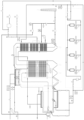
- the assembly depicted in the drawing comprises a group of rectification towers K1 to K4 which are, in their upper region, interconnected with a discharge piping 21 n, said discharge piping opening into an oil shower 23.
- An inlet piping 25 is connected to the oil shower 23, wherein said inlet piping 25 branches and its inlet branches then open into the interior of a combustion furnace 10.
- each of the inlet branches forms a coaxially arranged rim along its circumference, and is provided with several nozzles arranged with a uniform mutual angular spacing, wherein the direction of the nozzles comprises a tangential component to produce a vortex, thus thoroughly mixing the gas mixture from upper regions of the tanks K1 to K4 with the fuel fed by a burner 13.
- the combustion furnace 10 essentially has a shape of a horizontally arranged cylinder whose interior walls are formed by lining 11 and is surrounded by a membrane wall 12 from the outer side.
- the membrane wall 12 is a group of pipes which are mutually interconnected by means of strip metal and together form a gas-tight casing, wherein oil flows through said pipes.
- the membrane wall 12 is connected to a thermal oil heater 15.
- the membrane wall is a part of a preferred embodiment and is not essential for the invention.
- a burner 13 is arranged at one end of the combustion furnace 10.
- the burner 13 is a double-fuel burner for combustion of oil and gas.
- the combustion furnace 10 opens into an after-combustion chamber 14 in the form of a vertical cylinder whose upper region, i.e. a flue gas discharge region, is connected to a first pass-through chamber 61.
- a thermal oil heater 15 is arranged in the first pass-through chamber 61, wherein said chamber has a U-shaped curved longitudinal axis in the present embodiment.
- the thermal oil heater 15 is formed by tube-like and/or membrane systems arranged in the trajectory of the flue gas and designed for guiding the heated thermal oil and for conveying the heat from the flue gas to the oil.
- a flue gas outlet from the first pass-through chamber 61 opens into a second pass-through chamber 62 in which an additional heat exchanger 16 is arranged, wherein a supplementary heat exchanger 17 is arranged downstream of the additional heat exchanger 16 and, downstream of said supplementary heat exchanger 17, a flue gas discharge opens into a chimney 100 through a flue gas blower 18 and a flue gas exhaust piping 19.
- the additional heat exchanger 16 as well as the supplementary heat exchanger 17 are formed by tube-like and/or membrane systems for guiding of the heated air.
- the assembly furthermore comprises a compressor 31 which is interconnected to an additional piping 33 via a pressurized air tank 32, wherein said additional piping 33 opens into a system for guiding of heated pressurized air in the additional heat exchanger 16.
- the outlet of the heated pressurized air from said additional heat exchanger 16 opens into a transfer piping 34 for the heated pressurized air, wherein said transfer piping 34 branches out to a interconnecting piping 35 which opens into a inlet piping 25 for the gas mixture, and to a inlet piping 36 for pressurized air which is intended to input the heated rectification pressurized air and which, in this embodiment, branches out to partial branches and the individual partial branches are interconnected with inlets for rectification air into the rectification tanks K1 to K4.
- the assembly further comprises a bypass piping 40 which interconnects the outlet of the air tank 32 with the pressurized air inlet piping 36.
- the supplementary heat exchanger 17 is connected to the surrounding air with its inlet, and is connected to the feeding piping 51 with its output via a combustion air blower 50, said feeding piping 51 opening into the burner 13 with its outlet.
- a branch pipe 52 is arranged downstream of the flue gas blower 18, said branch pipe optionally interconnecting the exhaust piping 19 with the inlet on the intake portion of the combustion air blower 50.
- non-depicted heating bodies comprising thermal oil are arranged, e.g. heat-transferring coils for heating of asphalt.
- the outlet of the heating bodies comprising thermal oil is interconnected with the inlet of the of the thermal oil heater 15 whose outlet for oil is interconnected with the inlet of the membrane wall 12 of the combustion furnace 10 and the inlet of a (not depicted) membrane exchanger assembly which surrounds the thermal oil heater 15.
- the outlet of oil from the membrane walls 12 and the membrane exchanger assembly surrounding the thermal oil heater 15 opens into a (not depicted) heating assembly which heats the rectification towers K1 to K4 and/or (not depicted) storage tanks by means of heating bodies comprising thermal oil, wherein the outlet of the heating bodies comprising thermal oil is interconnected with the thermal oil heater 15.
- the assembly further comprises sensors and measurement devices for measurement of temperature, flow rate and pressure in various locations of the assembly, particularly temperature sensors T, pressure sensors P, flow rate sensors Q, oxygen content sensors O2, nitrogen oxides content sensor NOx and carbon monoxide content sensors CO.
- system further comprises a supplementary air blower 39 which opens into the additional piping 33 via a regulating piping.
- valves and flaps for a selective opening and closing of the respective pipelines and pipeline branches.
- the assembly functions as follows: Within the rectification tanks K1 to K4 and/or within the storage tanks, asphalt is heated by means of heating bodies, or rather heat-transferring coils, through which the heated thermal oil flows.
- the gas mixture formed by passage of the pressurized air through the liquid asphalt accumulates, or rather the gas mixture from the upper regions of the rectification tanks K1 to K4, which is drained by the discharge piping 21 to the oil shower 23 in which it is cooled to a temperature of approximately 100 °C, and is further guided to the inlet piping 25 for the gas mixture in which it branches out to individual branches by means of which it is fed to the interior of the combustion furnace 10.
- oil and/or gas is fed by the burner to the combustion furnace 10, said oil and/or gas being burned in the combustion furnace 10 along with the gas mixture fed by the inlet piping 25 for gas mixture.
- the flue gases from the combustion furnace 10 are guided through the after-combustion chamber 14 to the first pass-through chamber 61 in which they pass along the surfaces of the thermal oil heater 15; in a preferred embodiment, they also pass along the membrane walls surrounding the thermal oil heater 15, thus heating the thermal oil.
- the flue gases are guided from the first pass-through chamber 61 to the second pass-through chamber 62 in which they pass along the surfaces of the additional heat exchanger 16 and, in the illustrated embodiment, subsequently pass along the surfaces of the supplementary heat exchanger 17.
- the flue gases are guided through the flue gas blower 18 which ensures a required pull, and are subsequently guided through the exhaust piping 19 into the chimney 100.
- This optional discharge is regulated by a (not depicted) regulation unit which controls a closing-regulating flap in the branch pipe 52 and/or a closing-regulating flap in the exhaust piping 19 and/or a closing-regulating flap which is in the suction piping 80 for suction of air into the supplementary heat exchanger 17.
- the thermal oil heated by the thermal oil heater 15 in the first pass-through chamber 61 is guided into the membrane wall 12 of the combustion furnace 10 or eventually into the membrane wall surrounding the thermal oil heater 15, in which its temperature further rises, and is subsequently guided into a (not depicted) heating device in which the temperature is increased such that it exceeds approximately 240 °C. Afterwards, the thermal oil is guided into the heat-transferring coils in the rectification tanks K1 to K4 and/or to the heat-transferring coils in the (not depicted) asphalt storage tanks in which it heats the asphalt and subsequently is guided to the thermal oil heater 15 in the first pass-through chamber 61.
- the compressor 31 produces pressurized air which is fed through the pressurized air tank 32 via the additional piping 33 into the additional heat exchanger 16 in which it is heated by the flue gases. Afterwards, it is guided through the transfer piping 34 and the inlet piping 36 for pressurized air, or rather through its inlet branches to the individual rectification tanks K1 a K4, and forced through nozzles near the bottom into the liquid asphalt.
- this air mixes the asphalt and accumulates in the upper region together with other aromatic and other volatile compounds.
- This gas mixture is guided from said upper region through the discharge piping 21.
- the heat from the flue gases is recovered into the combustion chamber 10 which likewise enhances the efficiency of the system.
- the amount of flue gases leaving to the chimney is increased. This also enhances the efficiency of the system.
- the recirculation of flue gases likewise reduces the amount of arising NOx and the total amount of emissions discharged into the surrounding environment.
- the individual parts of the assembly illustrated in the drawings e.g. the sensors, the valves, the compressor, the burner, the air blowers, the closing flaps etc. are preferably interconnected with a (not depicted) control unit for controlling the entire system or at least the given assembly.
Landscapes
- Engineering & Computer Science (AREA)
- Chemical & Material Sciences (AREA)
- Chemical Kinetics & Catalysis (AREA)
- Environmental & Geological Engineering (AREA)
- General Chemical & Material Sciences (AREA)
- Mechanical Engineering (AREA)
- General Engineering & Computer Science (AREA)
- Structural Engineering (AREA)
- Civil Engineering (AREA)
- Materials Engineering (AREA)
- Oil, Petroleum & Natural Gas (AREA)
- Organic Chemistry (AREA)
- Physics & Mathematics (AREA)
- Thermal Sciences (AREA)
- Combustion & Propulsion (AREA)
- Water Supply & Treatment (AREA)
- Road Paving Machines (AREA)
- Working-Up Tar And Pitch (AREA)
Applications Claiming Priority (1)
| Application Number | Priority Date | Filing Date | Title |
|---|---|---|---|
| CZ2023-474A CZ310284B6 (cs) | 2023-12-08 | 2023-12-08 | Sestava, zařízení a způsob pro vedení vzduchu do rektifikační nebo skladovací nádrže na tekutý asfalt |
Publications (1)
| Publication Number | Publication Date |
|---|---|
| EP4567092A1 true EP4567092A1 (fr) | 2025-06-11 |
Family
ID=93924280
Family Applications (1)
| Application Number | Title | Priority Date | Filing Date |
|---|---|---|---|
| EP24217834.1A Pending EP4567092A1 (fr) | 2023-12-08 | 2024-12-05 | Ensemble de guidage d'air dans un réservoir de rectification ou de stockage d'asphalte liquide, dispositif et procédé |
Country Status (5)
| Country | Link |
|---|---|
| EP (1) | EP4567092A1 (fr) |
| CZ (1) | CZ310284B6 (fr) |
| HU (1) | HUP2400555A1 (fr) |
| PL (1) | PL450500A1 (fr) |
| SK (1) | SK500682024A3 (fr) |
Citations (3)
| Publication number | Priority date | Publication date | Assignee | Title |
|---|---|---|---|---|
| US2122764A (en) * | 1930-01-31 | 1938-07-05 | Foster Wheeler Corp | Production of blown asphalt |
| HU184687B (en) * | 1978-01-19 | 1984-09-28 | Komaromi Koeolajipari Vallalat | Process for theair blowing bituminous raw materials derived from mineral oil |
| CN201588159U (zh) * | 2010-01-26 | 2010-09-22 | 菏泽市公路管理局工程三处 | 一种储罐沥青均衡升温装置 |
Family Cites Families (7)
| Publication number | Priority date | Publication date | Assignee | Title |
|---|---|---|---|---|
| US1942656A (en) * | 1929-12-09 | 1934-01-09 | Standard Oil Co | Asphalt from blown petroleum residuums |
| GB2337329B (en) * | 1997-04-30 | 2001-09-05 | Imp Cancer Res Tech | Inhibitors of nuclear protein/nuclear receptor interaction |
| NZ534302A (en) * | 2004-07-23 | 2007-10-26 | John Brodie Matthews | Process and apparatus for oxidising bitumen to modify its properties |
| WO2014035262A1 (fr) * | 2012-08-31 | 2014-03-06 | John Brodie Matthews | Réacteur et procédés |
| DE102015222284A1 (de) * | 2015-11-12 | 2017-05-18 | Benninghoven GmbH & Co. KG Mülheim | Anlage und Verfahren zum Herstellen von Asphalt |
| CN211424698U (zh) * | 2019-11-11 | 2020-09-04 | 廊坊德基机械科技有限公司 | 用于沥青搅拌站的导热油炉烟气余热回收利用装置 |
| CN118995255B (zh) * | 2024-08-30 | 2025-11-21 | 福建省铁拓机械股份有限公司 | 一种节能型厂拌热再生组合设备及生产方法 |
-
2023
- 2023-12-08 CZ CZ2023-474A patent/CZ310284B6/cs unknown
-
2024
- 2024-12-04 HU HU2400555A patent/HUP2400555A1/hu unknown
- 2024-12-04 SK SK50068-2024A patent/SK500682024A3/sk unknown
- 2024-12-05 EP EP24217834.1A patent/EP4567092A1/fr active Pending
- 2024-12-06 PL PL450500A patent/PL450500A1/pl unknown
Patent Citations (3)
| Publication number | Priority date | Publication date | Assignee | Title |
|---|---|---|---|---|
| US2122764A (en) * | 1930-01-31 | 1938-07-05 | Foster Wheeler Corp | Production of blown asphalt |
| HU184687B (en) * | 1978-01-19 | 1984-09-28 | Komaromi Koeolajipari Vallalat | Process for theair blowing bituminous raw materials derived from mineral oil |
| CN201588159U (zh) * | 2010-01-26 | 2010-09-22 | 菏泽市公路管理局工程三处 | 一种储罐沥青均衡升温装置 |
Also Published As
| Publication number | Publication date |
|---|---|
| CZ2023474A3 (cs) | 2025-01-22 |
| PL450500A1 (pl) | 2025-06-09 |
| SK500682024A3 (sk) | 2025-10-15 |
| CZ310284B6 (cs) | 2025-01-22 |
| HUP2400555A1 (hu) | 2025-06-28 |
Similar Documents
| Publication | Publication Date | Title |
|---|---|---|
| RU2489492C2 (ru) | Способ рециркуляции доменного газа и устройство для его осуществления | |
| CN109668157B (zh) | 废气催化焚烧处理系统及其调节控制方法 | |
| CN109790978A (zh) | 用于操作克劳斯燃烧器的方法 | |
| CN113046101A (zh) | 一种焦炉处理化产voc烟道废气循环系统 | |
| CN207585344U (zh) | 一种管式加热炉的节能减排供排气系统 | |
| CN111981489B (zh) | 焚烧炉二燃室烟温自调节系统 | |
| EP4567092A1 (fr) | Ensemble de guidage d'air dans un réservoir de rectification ou de stockage d'asphalte liquide, dispositif et procédé | |
| CN207646148U (zh) | 一种处理碎煤加压气化煤制天然气尾气中挥发性有机物的系统 | |
| US3397028A (en) | High-temperature fuel element apparatus | |
| US20160228816A1 (en) | Reactor Apparatus and Method for Reducing NOx from Exhaust Gases Produced by Industrial Processes | |
| CN109749804A (zh) | 一种处理碎煤加压气化煤制天然气尾气中挥发性有机物的系统及方法 | |
| RU74689U1 (ru) | Огневой нейтрализатор промышленных стоков | |
| US2514084A (en) | Apparatus for supplying heated air to blast furnaces and the like | |
| CN210107430U (zh) | 适于处理挥发性有机物尾气的催化焚烧处理系统 | |
| CN115949950A (zh) | 有机固废阴燃处理系统及方法 | |
| WO2009018476A1 (fr) | Systèmes de four de re-cuisson et tunnel avec émissions réduites d'oxydes d'azote | |
| CN223228421U (zh) | 一种用于油田的rto系统 | |
| KR101868155B1 (ko) | 가열 장치 | |
| EA018713B1 (ru) | Способ сжигания материалов | |
| CN218155450U (zh) | 一种宽体辊道窑 | |
| JP7529333B1 (ja) | 燃焼装置 | |
| US12460814B2 (en) | Low NOx gas burner with cooled flue gas recycle | |
| CN211726939U (zh) | 土壤异位修复外热双位螺旋式烘干焙烧窑 | |
| Gaba et al. | Recovery of waste gas by combustion in an originally designed plant | |
| RU2575890C2 (ru) | Нагревательное устройство |
Legal Events
| Date | Code | Title | Description |
|---|---|---|---|
| PUAI | Public reference made under article 153(3) epc to a published international application that has entered the european phase |
Free format text: ORIGINAL CODE: 0009012 |
|
| STAA | Information on the status of an ep patent application or granted ep patent |
Free format text: STATUS: THE APPLICATION HAS BEEN PUBLISHED |
|
| AK | Designated contracting states |
Kind code of ref document: A1 Designated state(s): AL AT BE BG CH CY CZ DE DK EE ES FI FR GB GR HR HU IE IS IT LI LT LU LV MC ME MK MT NL NO PL PT RO RS SE SI SK SM TR |
|
| STAA | Information on the status of an ep patent application or granted ep patent |
Free format text: STATUS: REQUEST FOR EXAMINATION WAS MADE |
|
| 17P | Request for examination filed |
Effective date: 20251118 |