EP4570686A1 - Dispositif de stockage et/ou de transport en plastique pour la présentation de marchandises, son utilisation et procédé associé - Google Patents
Dispositif de stockage et/ou de transport en plastique pour la présentation de marchandises, son utilisation et procédé associé Download PDFInfo
- Publication number
- EP4570686A1 EP4570686A1 EP24218583.3A EP24218583A EP4570686A1 EP 4570686 A1 EP4570686 A1 EP 4570686A1 EP 24218583 A EP24218583 A EP 24218583A EP 4570686 A1 EP4570686 A1 EP 4570686A1
- Authority
- EP
- European Patent Office
- Prior art keywords
- reusable
- plastic
- transport device
- flat
- receiving section
- Prior art date
- Legal status (The legal status is an assumption and is not a legal conclusion. Google has not performed a legal analysis and makes no representation as to the accuracy of the status listed.)
- Pending
Links
Images

Classifications
-
- B—PERFORMING OPERATIONS; TRANSPORTING
- B65—CONVEYING; PACKING; STORING; HANDLING THIN OR FILAMENTARY MATERIAL
- B65D—CONTAINERS FOR STORAGE OR TRANSPORT OF ARTICLES OR MATERIALS, e.g. BAGS, BARRELS, BOTTLES, BOXES, CANS, CARTONS, CRATES, DRUMS, JARS, TANKS, HOPPERS, FORWARDING CONTAINERS; ACCESSORIES, CLOSURES, OR FITTINGS THEREFOR; PACKAGING ELEMENTS; PACKAGES
- B65D19/00—Pallets or like platforms, with or without side walls, for supporting loads to be lifted or lowered
- B65D19/0004—Rigid pallets without side walls
-
- B—PERFORMING OPERATIONS; TRANSPORTING
- B65—CONVEYING; PACKING; STORING; HANDLING THIN OR FILAMENTARY MATERIAL
- B65D—CONTAINERS FOR STORAGE OR TRANSPORT OF ARTICLES OR MATERIALS, e.g. BAGS, BARRELS, BOTTLES, BOXES, CANS, CARTONS, CRATES, DRUMS, JARS, TANKS, HOPPERS, FORWARDING CONTAINERS; ACCESSORIES, CLOSURES, OR FITTINGS THEREFOR; PACKAGING ELEMENTS; PACKAGES
- B65D19/00—Pallets or like platforms, with or without side walls, for supporting loads to be lifted or lowered
- B65D19/02—Rigid pallets with side walls, e.g. box pallets
- B65D19/06—Rigid pallets with side walls, e.g. box pallets with bodies formed by uniting or interconnecting two or more components
-
- B—PERFORMING OPERATIONS; TRANSPORTING
- B65—CONVEYING; PACKING; STORING; HANDLING THIN OR FILAMENTARY MATERIAL
- B65D—CONTAINERS FOR STORAGE OR TRANSPORT OF ARTICLES OR MATERIALS, e.g. BAGS, BARRELS, BOTTLES, BOXES, CANS, CARTONS, CRATES, DRUMS, JARS, TANKS, HOPPERS, FORWARDING CONTAINERS; ACCESSORIES, CLOSURES, OR FITTINGS THEREFOR; PACKAGING ELEMENTS; PACKAGES
- B65D2519/00—Pallets or like platforms, with or without side walls, for supporting loads to be lifted or lowered
- B65D2519/00004—Details relating to pallets
- B65D2519/00009—Materials
- B65D2519/00014—Materials for the load supporting surface
- B65D2519/00034—Plastic
-
- B—PERFORMING OPERATIONS; TRANSPORTING
- B65—CONVEYING; PACKING; STORING; HANDLING THIN OR FILAMENTARY MATERIAL
- B65D—CONTAINERS FOR STORAGE OR TRANSPORT OF ARTICLES OR MATERIALS, e.g. BAGS, BARRELS, BOTTLES, BOXES, CANS, CARTONS, CRATES, DRUMS, JARS, TANKS, HOPPERS, FORWARDING CONTAINERS; ACCESSORIES, CLOSURES, OR FITTINGS THEREFOR; PACKAGING ELEMENTS; PACKAGES
- B65D2519/00—Pallets or like platforms, with or without side walls, for supporting loads to be lifted or lowered
- B65D2519/00004—Details relating to pallets
- B65D2519/00009—Materials
- B65D2519/00049—Materials for the base surface
- B65D2519/00069—Plastic
-
- B—PERFORMING OPERATIONS; TRANSPORTING
- B65—CONVEYING; PACKING; STORING; HANDLING THIN OR FILAMENTARY MATERIAL
- B65D—CONTAINERS FOR STORAGE OR TRANSPORT OF ARTICLES OR MATERIALS, e.g. BAGS, BARRELS, BOTTLES, BOXES, CANS, CARTONS, CRATES, DRUMS, JARS, TANKS, HOPPERS, FORWARDING CONTAINERS; ACCESSORIES, CLOSURES, OR FITTINGS THEREFOR; PACKAGING ELEMENTS; PACKAGES
- B65D2519/00—Pallets or like platforms, with or without side walls, for supporting loads to be lifted or lowered
- B65D2519/00004—Details relating to pallets
- B65D2519/00547—Connections
- B65D2519/00636—Connections structures connecting side walls to the pallet
- B65D2519/00641—Structures intended to be disassembled
Definitions
- the present invention relates to a reusable storage and/or reusable transport device made of plastic for the presentation of goods, its fastening mechanism for optional side walls and its use.
- so-called display pallets are known, which are used for product presentation in salesrooms. These display pallets feature so-called displays made of cardboard or plastic, which are positively connected to the pallet forming the base. For this purpose, the displays can, for example, have a fold that is then clamped between the top of the pallet and the product, so that the display is held in place by the product.
- the object of the present invention is to provide a reusable storage and/or reusable transport device made of plastic for the presentation of goods, which enables a clean and resilient attachment of removable side walls.
- the essence of the present invention is to provide a flat, reusable storage and/or transport device made of plastic for product presentation.
- This device comprises at least one flat carrier element, which has a goods carrier upper side and a carrier lower side facing away therefrom, wherein the goods carrier upper side and the carrier lower side are connected to one another via at least one circumferential edge, wherein the circumferential edge has at least one receiving section and wherein the carrier element, which is connected to the rear side of the Receiving section, has at least one material taper.
- This is advantageous because the receiving section creates the possibility of optionally attaching a side wall to the flat, reusable storage and/or reusable transport device made of plastic for product presentation.
- the receiving section is designed such that an optionally arranged side wall can be inserted into the receiving section.
- an optionally arranged side wall can be inserted into the receiving section from above, from the side, or even diagonally.
- the additionally provided material taper of the support element advantageously creates a free space underneath, thus enabling particularly easy handling of the flat, reusable storage and/or reusable transport device made of plastic.
- the material taper of the support element is designed such that the support element still has a continuous goods carrier top.
- the material thickness is reduced in the area of the material taper.
- an additional free space is created below the material taper.
- the material taper is advantageously formed directly adjacent to the receiving section in the edge region of the support element.
- the at least one receiving section is at least partially integrated into the peripheral edge or placed on it If the receiving section is integrated into the surrounding edge, it is particularly stable and break-resistant. This can be taken into account during the production of the flat, reusable storage and/or transport device made of plastic.
- the receiving section can be designed as a slot.
- the tab-like element can be at least partially inserted into this slot and securely received therein.
- the receiving section has at least one guide element.
- This at least one guide element is advantageous when a side wall is to be arranged on the flat, reusable storage and/or transport device made of plastic.
- the at least one guide element serves as an insertion and stabilization aid.
- the receiving section is designed as a guide slot or as a recess with at least one guide element.
- the at least one guide element is designed as a groove or dovetail profile.
- the groove design has proven advantageous because it can be formed particularly easily during the injection molding process.
- the groove can have a square, round, or rounded profile. Have a cross-section.
- the tab-like element that can optionally be arranged at least partially therein is designed to complement the groove. This ensures secure guidance. It has proven particularly advantageous if the receiving section has two groove-like guide elements that are arranged at the edges. The guide elements then advantageously delimit a recess on the side into which the optionally arranged tab-like element can be inserted and guided.
- the dovetail profile design has proven advantageous in that it allows for a particularly stable connection to the side wall. If the at least one guide element is designed as a dovetail profile, the tab-like element, which can optionally be arranged at least partially within it, is designed to complement the profile. This ensures secure guidance.
- a lower free end of the receiving portion is designed as a retaining element.
- at least one retaining element is formed.
- the at least one projection advantageously extends downward in a wedge shape.
- the wedge shape is particularly advantageously configured such that the wedge shape is larger at a front end of the receiving portion and decreases in size toward the material taper.
- a further advantageous embodiment presents a flat, reusable storage and/or transport device made of plastic for product presentation, which further comprises at least one upwardly extending side wall for spanning a product presentation volume, which has at least one tab-like element on a lower edge, which can be received by the receiving section and which at least partially engages behind and/or under the at least one retaining element in a form-fitting and/or force-fitting manner. Unwanted slipping out of the interior volume is thus no longer possible.
- the tab-like element has at least one locking element.
- the locking element is formed integrally with the tab-like element.
- the punched-out shape advantageously takes on a U-shape.
- the locking element can be deflected about a vertical pivot axis or a horizontal pivot axis, in each case under pressure.
- the locking element can be deflected from its original position particularly easily and quickly by applying pressure, for example by a finger.
- the deflection occurs by pivoting the locking element backward into the free space. This pivoting can occur horizontally or vertically. Through this change in position, the locking element forms a force-locking and/or form-locking connection with the receiving section, more advantageously with the at least one retaining element.
- the locking element is also conceivable for the locking element to be additionally resilient and to form a positive and/or non-positive connection with the receiving portion, advantageously with the at least one retaining element, even without the application of external compressive force.
- a possible resilient property can be created, for example, by a suitable choice of material.
- a tab-like element of a side wall is inserted into the receiving section from above. This is the simplest and quickest arrangement option, although this is of course not intended to be limiting. It is also conceivable that the insertion into the receiving section could occur laterally or at an angle.
- the tab-like element of a side wall can also be inserted, for example pressed or clicked into the receiving section, by applying a lateral compressive force, for example to a central region of the tab-like element.
- the tab-like element is designed at its lateral edges so that it can be inserted precisely into the receiving section.
- a precise fit means that it allows for quick and easy insertion without jamming or slipping.
- the tab-like element is inserted from top to bottom until the locking element is positioned at the same height as or below the free end of the receiving section.
- the locking element is located, at least in part, above the free end of the receiving section. Even in this position, it is possible to deflect the locking element by applying pressure to it, so that advantageously a positive and/or non-positive engagement of the receiving section is made possible.
- sufficient deflection of the at least one locking element only occurs when a compressive force is applied. Applying a compressive force to the locking element causes it to change its position, advantageously around a horizontal or vertical pivot axis. This change in position remains even if the compressive force is discontinued. This is advantageous because the change in the position of the locking element can ensure a positive and/or non-positive engagement under and/or behind the at least one retaining element of the receiving section.
- the locking element is not designed to be resilient.
- the change in position ensures that the tab-like element as a whole and the side wall arranged thereon are held securely and firmly on the receiving section.
- the at least one locking element remains in interaction with the at least one retaining element, thus permanently ensuring a secure and reliable fastening between the side wall and the flat, reusable storage and/or transport device made of plastic.
- the present invention also relates to the use of a flat reusable storage and/or reusable transport device made of plastic for Sales promotion and presentation of products and/or as a display pallet.
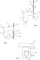
- Figure 1 a schematic side view of an insertion position of a first embodiment of the fastening mechanism is shown.
- the flat, reusable storage and/or transport device made of plastic 1 has a flat support element 2.
- This support element 2 further has a goods carrier upper side 4 and a carrier lower side 6 facing away from it.
- the goods carrier upper side 4 and the carrier lower side 6 are connected to one another by a circumferential edge 8.
- the peripheral edge 8 has a receiving portion 10 which is suitable for receiving a tab-like element 24 which is part of a side wall (not shown here).
- the receiving section 10 can be designed as a guide slot or as a recess with at least one guide element.
- a material taper 12 of the carrier element 2 is formed on the rear side of the receiving section 10.
- a retaining element 18 is formed, as an example, at the lower free end 14 of the receiving section 10.
- the shown retaining element 18 is formed integrally with the receiving section 10.
- the shown retaining element 18 is wedge-shaped and tapers in the direction of the material taper 12; more advantageously, it tapers in the direction of the center of the reusable storage and/or reusable transport device (not shown here).
- a tab-like element 24 is shown, which is inserted into the receiving section 10 in direction D, here from top to bottom.
- the receiving section 10 and the tab-like element 24 form common contact surfaces, for example in the guide grooves, so that the tab-like element 24 can be secured against lateral tilting.
- Figure 2 shows a side view of a first embodiment of a fastening mechanism of a side wall on a flat reusable storage and/or reusable transport device made of plastic 1 in the fastening position.
- the tab-like element 24 is now inserted into the receiving section 10. The insertion is continued until the locking element 20 is positioned at the level of the retaining element 18 or below the retaining element 18. If a further pressure force P is then exerted on the locking element 20 in the direction of the arrow, the Locking element 20 along a vertical pivot axis (not shown here) backwards in the direction of free space 26.
- the locking element 20 engages under and/or behind the receiving section 10, more advantageously the locking element 20, at least in sections, in a form-fitting and/or force-fitting manner.
- the tab-like element 24 is to be pulled vertically upwards out of the receiving section 10.
- the locking element 20 is then guided against the receiving section 10 and/or against the material taper 12 and held there. Further movement of the tab-like element 24 in the vertical upward direction is not possible.
- a sufficient and reliable arrangement of the tab-like element 24 and the side wall arranged thereon can be achieved on a flat reusable storage and/or reusable transport device made of plastic 1.
- FIG 3 a corresponding front view of a section of a side wall 22 with a downwardly extending tab-like element 24 arranged thereon is shown.
- the tab-like element 24 has a locking element 20, which is designed here as a pivotable tab.
- the design can, for example, be such that the locking element 20 is punched out in a U-shape.
- the pivot axis S1 is arranged opposite the base of the U-shaped opening. Along the pivot axis S1, it is possible to deflect and pivot the locking element 20.
- the pivot axis S1 extends in the vertical direction.
- the locking element 20 has a fold or perforations at least in sections along the pivot axis S1. As a result, the pivoting, for example in the form of folding backwards, can be carried out particularly easily and quickly.
- Figure 4 a schematic side view of an insertion position of a second embodiment of the fastening mechanism is shown.
- the flat, reusable storage and/or transport device made of plastic 1 has a flat support element 2.
- This support element 2 further has a goods carrier upper side 4 and a carrier lower side 6 facing away from it.
- the goods carrier upper side 4 and the carrier lower side 6 are connected to one another by a circumferential edge 8.
- the peripheral edge 8 has a receiving portion 10, which is suitable for receiving a tab-like element 24, which is part of a side wall (not shown here).
- the receiving portion 10 can be designed as a guide slot or as a recess with at least one guide element.
- a material taper 12 of the support element 2 is formed on the rear side of the receiving portion 10.
- a retaining element 18 is formed, as an example, at the lower free end 14 of the receiving section 10.
- the shown retaining element 18 is formed integrally with the receiving section 10.
- the shown retaining element 18 is wedge-shaped and tapers in the direction of the material taper 12; more advantageously, it tapers in the direction of the center of the reusable storage and/or reusable transport device (not shown here).
- a tab-like element 24 is shown, which is inserted into the receiving section 10 in direction D, here from top to bottom.
- the receiving section 10 and the tab-like element 24 form common contact surfaces, for example in the guide grooves, so that the tab-like element 24 can be secured against lateral tilting.
- the tab-like element 24 has a locking element 28.
- Figure 5 shows a side view of a second embodiment of a fastening mechanism of a side wall (not shown here) on a flat, reusable storage and/or transport device 1 made of plastic in the fastening position.
- the tab-like element 24 is now inserted into the receiving section 10. The insertion continues until the locking element 28 is positioned at the level of the retaining element 18 or below the retaining element 18. If a further compressive force P is then exerted on the locking element 28 in the direction of the arrow, the locking element 28 pivots backwards along a horizontal pivot axis (not shown here) towards the free space 26.
- the locking element 20 engages at least partially under the receiving section 10, more advantageously the locking element 20, in a form-fitting and/or force-fitting manner.
- This provides sufficient fastening, for example when the tab-like element 24 is to be pulled out vertically upwards again.
- the locking element 28 is then guided against the receiving section 10 and/or against the material taper 12 and held there. A further movement of the tab-like element 24 in the vertical direction upwards is not possible.
- a sufficient and reliable arrangement of the tab-like element 24 and the side wall arranged thereon can be achieved on a flat, reusable storage and/or reusable transport device 1 made of plastic.
- FIG 6 a corresponding front view of a section of a side wall 22 with a further tab-like element 24 arranged thereon and extending downwards is shown.
- the tab-like element 24 has a locking element 28, which here is designed as a pivotable tab.
- the design can, for example, be such that the locking element 28 is punched out in a U-shape.
- the pivot axis S2 is arranged opposite the base of the U-shaped opening.
- the locking element 28 can be deflected and pivoted along the pivot axis S2.
- the pivot axis S2 particularly advantageously extends in the horizontal direction.
- the locking element 28 has a fold or perforations at least in sections along the pivot axis S2. This allows the pivoting, for example in the form of folding backwards, to take place particularly easily and quickly.
Landscapes
- Engineering & Computer Science (AREA)
- Mechanical Engineering (AREA)
- Pallets (AREA)
- Details Of Rigid Or Semi-Rigid Containers (AREA)
Applications Claiming Priority (1)
| Application Number | Priority Date | Filing Date | Title |
|---|---|---|---|
| DE102023134863.9A DE102023134863A1 (de) | 2023-12-12 | 2023-12-12 | Flächig ausgebildete Mehrweglager- und/oder Mehrwegtransportvorrichtung aus Kunststoff zur Warenpräsentation und deren Verwendung |
Publications (1)
| Publication Number | Publication Date |
|---|---|
| EP4570686A1 true EP4570686A1 (fr) | 2025-06-18 |
Family
ID=93852920
Family Applications (1)
| Application Number | Title | Priority Date | Filing Date |
|---|---|---|---|
| EP24218583.3A Pending EP4570686A1 (fr) | 2023-12-12 | 2024-12-10 | Dispositif de stockage et/ou de transport en plastique pour la présentation de marchandises, son utilisation et procédé associé |
Country Status (2)
| Country | Link |
|---|---|
| EP (1) | EP4570686A1 (fr) |
| DE (1) | DE102023134863A1 (fr) |
Citations (6)
| Publication number | Priority date | Publication date | Assignee | Title |
|---|---|---|---|---|
| DE9104762U1 (de) * | 1991-04-18 | 1992-08-13 | Schröter + Bake AG, 8402 Neutraubling | Bausatz für einen Warenbehälter |
| US5918551A (en) * | 1998-02-04 | 1999-07-06 | Liu; Ching Rong | Trestle stage |
| US20100126391A1 (en) * | 2007-04-23 | 2010-05-27 | Itella Oyj | Universal chassis |
| EP2878550A1 (fr) * | 2011-02-11 | 2015-06-03 | PAKI Logistics GmbH | Palette |
| EP2634107B1 (fr) * | 2012-03-02 | 2016-01-06 | Ds Smith Plastics France | Container et ceinture pour une palette |
| EP4046548A1 (fr) * | 2021-02-18 | 2022-08-24 | Hansjochen Geugelin | Fixation de quarts de palette à un socle de présentation |
Family Cites Families (2)
| Publication number | Priority date | Publication date | Assignee | Title |
|---|---|---|---|---|
| DE8334917U1 (de) * | 1983-12-06 | 1984-03-01 | August Storck Kg, 4802 Halle | Verkaufssteller fuer waren |
| DE202019104276U1 (de) * | 2019-08-02 | 2020-08-12 | Rickard Nilsson | Einhängebehältnis zum Einhängen an eine Traverse, Anordnung mit einem Einhängebehältnis und Regalsystem |
-
2023
- 2023-12-12 DE DE102023134863.9A patent/DE102023134863A1/de active Pending
-
2024
- 2024-12-10 EP EP24218583.3A patent/EP4570686A1/fr active Pending
Patent Citations (6)
| Publication number | Priority date | Publication date | Assignee | Title |
|---|---|---|---|---|
| DE9104762U1 (de) * | 1991-04-18 | 1992-08-13 | Schröter + Bake AG, 8402 Neutraubling | Bausatz für einen Warenbehälter |
| US5918551A (en) * | 1998-02-04 | 1999-07-06 | Liu; Ching Rong | Trestle stage |
| US20100126391A1 (en) * | 2007-04-23 | 2010-05-27 | Itella Oyj | Universal chassis |
| EP2878550A1 (fr) * | 2011-02-11 | 2015-06-03 | PAKI Logistics GmbH | Palette |
| EP2634107B1 (fr) * | 2012-03-02 | 2016-01-06 | Ds Smith Plastics France | Container et ceinture pour une palette |
| EP4046548A1 (fr) * | 2021-02-18 | 2022-08-24 | Hansjochen Geugelin | Fixation de quarts de palette à un socle de présentation |
Also Published As
| Publication number | Publication date |
|---|---|
| DE102023134863A1 (de) | 2025-06-12 |
Similar Documents
| Publication | Publication Date | Title |
|---|---|---|
| DE1805523C3 (de) | Trageinrichtung für Fachboden od.dgl. mit einem Tragarm | |
| DE2362529A1 (de) | Lagergestell mit fachboden und anschlussecken | |
| EP3636558A1 (fr) | Palette | |
| EP1473989A1 (fr) | Dispositif destine a recevoir des aliments pour animaux | |
| DE8803408U1 (de) | Halter für Werkzeuge und dgl. an Lochtafeln | |
| DE2643006A1 (de) | Vorrichtung zum zusammenheften eines stapels loser blaetter | |
| EP4570686A1 (fr) | Dispositif de stockage et/ou de transport en plastique pour la présentation de marchandises, son utilisation et procédé associé | |
| DE2353418A1 (de) | Fassungsvorrichtung | |
| DE3035669A1 (de) | Geraet mit mindestens zwei mittels einesm rasthakens loesbar miteinander verbundenen teilen | |
| EP2128046A1 (fr) | Elément de fixation pour une barre à rouleaux et couloir de roulement | |
| EP2990549A1 (fr) | Fente de drainage dotée d'une tige longitudinale amovible | |
| DE102019201395A1 (de) | Wandschalung mit Hülse für Ankerlöcher, Hülse und Reinigungsverfahren | |
| EP4570688A1 (fr) | Dispositif de stockage et/ou de transport en plastique pour la présentation de marchandises, son utilisation et procédé associé | |
| EP4570689A1 (fr) | Dispositif de stockage et/ou de transport en plastique pour la présentation de marchandises, son utilisation et procédé associé | |
| DE1554472B1 (de) | Vorrichtung an Regalen od.dgl. zum leicht loesbaren Verbinden eines Pfostens mit einem Tragstueck | |
| AT522677A4 (de) | Hilfsvorrichtung für das Verschieben einzelner oder mehrerer Zargen eines Bienenstocks | |
| DE202004014528U1 (de) | Seilschlaufenanordnung | |
| DE29808713U1 (de) | Abheftvorrichtung | |
| AT392164B (de) | Bildbetrachtungsgeraet | |
| DE29605758U1 (de) | Kragarmregal | |
| DE202023002815U1 (de) | Regalelementekombination | |
| DE3700041A1 (de) | Bewehrungs-abstandhalter | |
| DE4233935A1 (de) | An Teleskopschienen geführter schubladenartiger Behälter | |
| DE2433311A1 (de) | Anordnung zur verbindung duennwandiger, in einem abstand voneinander zu haltender hohlkoerper | |
| DE19916170B4 (de) | Abdeckung für eine feststehend angeordnete Führungsschiene eines Fahrzeugsitzes |
Legal Events
| Date | Code | Title | Description |
|---|---|---|---|
| PUAI | Public reference made under article 153(3) epc to a published international application that has entered the european phase |
Free format text: ORIGINAL CODE: 0009012 |
|
| STAA | Information on the status of an ep patent application or granted ep patent |
Free format text: STATUS: THE APPLICATION HAS BEEN PUBLISHED |
|
| AK | Designated contracting states |
Kind code of ref document: A1 Designated state(s): AL AT BE BG CH CY CZ DE DK EE ES FI FR GB GR HR HU IE IS IT LI LT LU LV MC ME MK MT NL NO PL PT RO RS SE SI SK SM TR |
|
| STAA | Information on the status of an ep patent application or granted ep patent |
Free format text: STATUS: THE APPLICATION IS DEEMED TO BE WITHDRAWN |