EP4570688A1 - Dispositif de stockage et/ou de transport en plastique pour la présentation de marchandises, son utilisation et procédé associé - Google Patents
Dispositif de stockage et/ou de transport en plastique pour la présentation de marchandises, son utilisation et procédé associé Download PDFInfo
- Publication number
- EP4570688A1 EP4570688A1 EP24218581.7A EP24218581A EP4570688A1 EP 4570688 A1 EP4570688 A1 EP 4570688A1 EP 24218581 A EP24218581 A EP 24218581A EP 4570688 A1 EP4570688 A1 EP 4570688A1
- Authority
- EP
- European Patent Office
- Prior art keywords
- reusable
- plastic
- transport device
- flat
- opening
- Prior art date
- Legal status (The legal status is an assumption and is not a legal conclusion. Google has not performed a legal analysis and makes no representation as to the accuracy of the status listed.)
- Pending
Links
Images


Classifications
-
- B—PERFORMING OPERATIONS; TRANSPORTING
- B65—CONVEYING; PACKING; STORING; HANDLING THIN OR FILAMENTARY MATERIAL
- B65D—CONTAINERS FOR STORAGE OR TRANSPORT OF ARTICLES OR MATERIALS, e.g. BAGS, BARRELS, BOTTLES, BOXES, CANS, CARTONS, CRATES, DRUMS, JARS, TANKS, HOPPERS, FORWARDING CONTAINERS; ACCESSORIES, CLOSURES, OR FITTINGS THEREFOR; PACKAGING ELEMENTS; PACKAGES
- B65D19/00—Pallets or like platforms, with or without side walls, for supporting loads to be lifted or lowered
- B65D19/0004—Rigid pallets without side walls
- B65D19/0006—Rigid pallets without side walls the load supporting surface being made of a single element
- B65D19/003—Rigid pallets without side walls the load supporting surface being made of a single element forming discontinuous or non-planar contact surfaces
- B65D19/0032—Rigid pallets without side walls the load supporting surface being made of a single element forming discontinuous or non-planar contact surfaces the base surface being made of a single element
- B65D19/0036—Rigid pallets without side walls the load supporting surface being made of a single element forming discontinuous or non-planar contact surfaces the base surface being made of a single element forming discontinuous or non-planar contact surfaces
- B65D19/004—Rigid pallets without side walls the load supporting surface being made of a single element forming discontinuous or non-planar contact surfaces the base surface being made of a single element forming discontinuous or non-planar contact surfaces and each contact surface having a discrete foot-like shape
-
- B—PERFORMING OPERATIONS; TRANSPORTING
- B65—CONVEYING; PACKING; STORING; HANDLING THIN OR FILAMENTARY MATERIAL
- B65D—CONTAINERS FOR STORAGE OR TRANSPORT OF ARTICLES OR MATERIALS, e.g. BAGS, BARRELS, BOTTLES, BOXES, CANS, CARTONS, CRATES, DRUMS, JARS, TANKS, HOPPERS, FORWARDING CONTAINERS; ACCESSORIES, CLOSURES, OR FITTINGS THEREFOR; PACKAGING ELEMENTS; PACKAGES
- B65D19/00—Pallets or like platforms, with or without side walls, for supporting loads to be lifted or lowered
- B65D19/02—Rigid pallets with side walls, e.g. box pallets
- B65D19/06—Rigid pallets with side walls, e.g. box pallets with bodies formed by uniting or interconnecting two or more components
-
- B—PERFORMING OPERATIONS; TRANSPORTING
- B65—CONVEYING; PACKING; STORING; HANDLING THIN OR FILAMENTARY MATERIAL
- B65D—CONTAINERS FOR STORAGE OR TRANSPORT OF ARTICLES OR MATERIALS, e.g. BAGS, BARRELS, BOTTLES, BOXES, CANS, CARTONS, CRATES, DRUMS, JARS, TANKS, HOPPERS, FORWARDING CONTAINERS; ACCESSORIES, CLOSURES, OR FITTINGS THEREFOR; PACKAGING ELEMENTS; PACKAGES
- B65D2519/00—Pallets or like platforms, with or without side walls, for supporting loads to be lifted or lowered
- B65D2519/00004—Details relating to pallets
- B65D2519/00009—Materials
- B65D2519/00014—Materials for the load supporting surface
- B65D2519/00034—Plastic
-
- B—PERFORMING OPERATIONS; TRANSPORTING
- B65—CONVEYING; PACKING; STORING; HANDLING THIN OR FILAMENTARY MATERIAL
- B65D—CONTAINERS FOR STORAGE OR TRANSPORT OF ARTICLES OR MATERIALS, e.g. BAGS, BARRELS, BOTTLES, BOXES, CANS, CARTONS, CRATES, DRUMS, JARS, TANKS, HOPPERS, FORWARDING CONTAINERS; ACCESSORIES, CLOSURES, OR FITTINGS THEREFOR; PACKAGING ELEMENTS; PACKAGES
- B65D2519/00—Pallets or like platforms, with or without side walls, for supporting loads to be lifted or lowered
- B65D2519/00004—Details relating to pallets
- B65D2519/00009—Materials
- B65D2519/00049—Materials for the base surface
- B65D2519/00069—Plastic
-
- B—PERFORMING OPERATIONS; TRANSPORTING
- B65—CONVEYING; PACKING; STORING; HANDLING THIN OR FILAMENTARY MATERIAL
- B65D—CONTAINERS FOR STORAGE OR TRANSPORT OF ARTICLES OR MATERIALS, e.g. BAGS, BARRELS, BOTTLES, BOXES, CANS, CARTONS, CRATES, DRUMS, JARS, TANKS, HOPPERS, FORWARDING CONTAINERS; ACCESSORIES, CLOSURES, OR FITTINGS THEREFOR; PACKAGING ELEMENTS; PACKAGES
- B65D2519/00—Pallets or like platforms, with or without side walls, for supporting loads to be lifted or lowered
- B65D2519/00004—Details relating to pallets
- B65D2519/00009—Materials
- B65D2519/00154—Materials for the side walls
- B65D2519/00159—Paper
-
- B—PERFORMING OPERATIONS; TRANSPORTING
- B65—CONVEYING; PACKING; STORING; HANDLING THIN OR FILAMENTARY MATERIAL
- B65D—CONTAINERS FOR STORAGE OR TRANSPORT OF ARTICLES OR MATERIALS, e.g. BAGS, BARRELS, BOTTLES, BOXES, CANS, CARTONS, CRATES, DRUMS, JARS, TANKS, HOPPERS, FORWARDING CONTAINERS; ACCESSORIES, CLOSURES, OR FITTINGS THEREFOR; PACKAGING ELEMENTS; PACKAGES
- B65D2519/00—Pallets or like platforms, with or without side walls, for supporting loads to be lifted or lowered
- B65D2519/00004—Details relating to pallets
- B65D2519/00009—Materials
- B65D2519/00154—Materials for the side walls
- B65D2519/00174—Plastic
-
- B—PERFORMING OPERATIONS; TRANSPORTING
- B65—CONVEYING; PACKING; STORING; HANDLING THIN OR FILAMENTARY MATERIAL
- B65D—CONTAINERS FOR STORAGE OR TRANSPORT OF ARTICLES OR MATERIALS, e.g. BAGS, BARRELS, BOTTLES, BOXES, CANS, CARTONS, CRATES, DRUMS, JARS, TANKS, HOPPERS, FORWARDING CONTAINERS; ACCESSORIES, CLOSURES, OR FITTINGS THEREFOR; PACKAGING ELEMENTS; PACKAGES
- B65D2519/00—Pallets or like platforms, with or without side walls, for supporting loads to be lifted or lowered
- B65D2519/00004—Details relating to pallets
- B65D2519/00258—Overall construction
- B65D2519/00263—Overall construction of the pallet
- B65D2519/00268—Overall construction of the pallet made of one piece
-
- B—PERFORMING OPERATIONS; TRANSPORTING
- B65—CONVEYING; PACKING; STORING; HANDLING THIN OR FILAMENTARY MATERIAL
- B65D—CONTAINERS FOR STORAGE OR TRANSPORT OF ARTICLES OR MATERIALS, e.g. BAGS, BARRELS, BOTTLES, BOXES, CANS, CARTONS, CRATES, DRUMS, JARS, TANKS, HOPPERS, FORWARDING CONTAINERS; ACCESSORIES, CLOSURES, OR FITTINGS THEREFOR; PACKAGING ELEMENTS; PACKAGES
- B65D2519/00—Pallets or like platforms, with or without side walls, for supporting loads to be lifted or lowered
- B65D2519/00004—Details relating to pallets
- B65D2519/00258—Overall construction
- B65D2519/00283—Overall construction of the load supporting surface
- B65D2519/00288—Overall construction of the load supporting surface made of one piece
-
- B—PERFORMING OPERATIONS; TRANSPORTING
- B65—CONVEYING; PACKING; STORING; HANDLING THIN OR FILAMENTARY MATERIAL
- B65D—CONTAINERS FOR STORAGE OR TRANSPORT OF ARTICLES OR MATERIALS, e.g. BAGS, BARRELS, BOTTLES, BOXES, CANS, CARTONS, CRATES, DRUMS, JARS, TANKS, HOPPERS, FORWARDING CONTAINERS; ACCESSORIES, CLOSURES, OR FITTINGS THEREFOR; PACKAGING ELEMENTS; PACKAGES
- B65D2519/00—Pallets or like platforms, with or without side walls, for supporting loads to be lifted or lowered
- B65D2519/00004—Details relating to pallets
- B65D2519/00258—Overall construction
- B65D2519/00283—Overall construction of the load supporting surface
- B65D2519/00308—Overall construction of the load supporting surface grid type, e.g. perforated plate
-
- B—PERFORMING OPERATIONS; TRANSPORTING
- B65—CONVEYING; PACKING; STORING; HANDLING THIN OR FILAMENTARY MATERIAL
- B65D—CONTAINERS FOR STORAGE OR TRANSPORT OF ARTICLES OR MATERIALS, e.g. BAGS, BARRELS, BOTTLES, BOXES, CANS, CARTONS, CRATES, DRUMS, JARS, TANKS, HOPPERS, FORWARDING CONTAINERS; ACCESSORIES, CLOSURES, OR FITTINGS THEREFOR; PACKAGING ELEMENTS; PACKAGES
- B65D2519/00—Pallets or like platforms, with or without side walls, for supporting loads to be lifted or lowered
- B65D2519/00004—Details relating to pallets
- B65D2519/00258—Overall construction
- B65D2519/00313—Overall construction of the base surface
- B65D2519/00318—Overall construction of the base surface made of one piece
-
- B—PERFORMING OPERATIONS; TRANSPORTING
- B65—CONVEYING; PACKING; STORING; HANDLING THIN OR FILAMENTARY MATERIAL
- B65D—CONTAINERS FOR STORAGE OR TRANSPORT OF ARTICLES OR MATERIALS, e.g. BAGS, BARRELS, BOTTLES, BOXES, CANS, CARTONS, CRATES, DRUMS, JARS, TANKS, HOPPERS, FORWARDING CONTAINERS; ACCESSORIES, CLOSURES, OR FITTINGS THEREFOR; PACKAGING ELEMENTS; PACKAGES
- B65D2519/00—Pallets or like platforms, with or without side walls, for supporting loads to be lifted or lowered
- B65D2519/00004—Details relating to pallets
- B65D2519/00258—Overall construction
- B65D2519/00313—Overall construction of the base surface
- B65D2519/00328—Overall construction of the base surface shape of the contact surface of the base
- B65D2519/00338—Overall construction of the base surface shape of the contact surface of the base contact surface having a discrete foot-like shape
-
- B—PERFORMING OPERATIONS; TRANSPORTING
- B65—CONVEYING; PACKING; STORING; HANDLING THIN OR FILAMENTARY MATERIAL
- B65D—CONTAINERS FOR STORAGE OR TRANSPORT OF ARTICLES OR MATERIALS, e.g. BAGS, BARRELS, BOTTLES, BOXES, CANS, CARTONS, CRATES, DRUMS, JARS, TANKS, HOPPERS, FORWARDING CONTAINERS; ACCESSORIES, CLOSURES, OR FITTINGS THEREFOR; PACKAGING ELEMENTS; PACKAGES
- B65D2519/00—Pallets or like platforms, with or without side walls, for supporting loads to be lifted or lowered
- B65D2519/00004—Details relating to pallets
- B65D2519/00547—Connections
- B65D2519/00577—Connections structures connecting side walls, including corner posts, to each other
- B65D2519/00582—Connections structures connecting side walls, including corner posts, to each other structures intended to be disassembled, i.e. collapsible or dismountable
- B65D2519/00587—Connections structures connecting side walls, including corner posts, to each other structures intended to be disassembled, i.e. collapsible or dismountable side walls directly connected to each other
- B65D2519/00592—Connections structures connecting side walls, including corner posts, to each other structures intended to be disassembled, i.e. collapsible or dismountable side walls directly connected to each other by means of hinges
- B65D2519/00597—Connections structures connecting side walls, including corner posts, to each other structures intended to be disassembled, i.e. collapsible or dismountable side walls directly connected to each other by means of hinges integrally formed
-
- B—PERFORMING OPERATIONS; TRANSPORTING
- B65—CONVEYING; PACKING; STORING; HANDLING THIN OR FILAMENTARY MATERIAL
- B65D—CONTAINERS FOR STORAGE OR TRANSPORT OF ARTICLES OR MATERIALS, e.g. BAGS, BARRELS, BOTTLES, BOXES, CANS, CARTONS, CRATES, DRUMS, JARS, TANKS, HOPPERS, FORWARDING CONTAINERS; ACCESSORIES, CLOSURES, OR FITTINGS THEREFOR; PACKAGING ELEMENTS; PACKAGES
- B65D2519/00—Pallets or like platforms, with or without side walls, for supporting loads to be lifted or lowered
- B65D2519/00004—Details relating to pallets
- B65D2519/00547—Connections
- B65D2519/00636—Connections structures connecting side walls to the pallet
- B65D2519/00641—Structures intended to be disassembled
-
- B—PERFORMING OPERATIONS; TRANSPORTING
- B65—CONVEYING; PACKING; STORING; HANDLING THIN OR FILAMENTARY MATERIAL
- B65D—CONTAINERS FOR STORAGE OR TRANSPORT OF ARTICLES OR MATERIALS, e.g. BAGS, BARRELS, BOTTLES, BOXES, CANS, CARTONS, CRATES, DRUMS, JARS, TANKS, HOPPERS, FORWARDING CONTAINERS; ACCESSORIES, CLOSURES, OR FITTINGS THEREFOR; PACKAGING ELEMENTS; PACKAGES
- B65D2519/00—Pallets or like platforms, with or without side walls, for supporting loads to be lifted or lowered
- B65D2519/00004—Details relating to pallets
- B65D2519/00736—Details
- B65D2519/00865—Collapsible, i.e. at least two constitutive elements remaining hingedly connected
- B65D2519/00875—Collapsible, i.e. at least two constitutive elements remaining hingedly connected collapsible side walls
- B65D2519/0091—Collapsible, i.e. at least two constitutive elements remaining hingedly connected collapsible side walls whereby all side walls are hingedly connected to each other
-
- B—PERFORMING OPERATIONS; TRANSPORTING
- B65—CONVEYING; PACKING; STORING; HANDLING THIN OR FILAMENTARY MATERIAL
- B65D—CONTAINERS FOR STORAGE OR TRANSPORT OF ARTICLES OR MATERIALS, e.g. BAGS, BARRELS, BOTTLES, BOXES, CANS, CARTONS, CRATES, DRUMS, JARS, TANKS, HOPPERS, FORWARDING CONTAINERS; ACCESSORIES, CLOSURES, OR FITTINGS THEREFOR; PACKAGING ELEMENTS; PACKAGES
- B65D2519/00—Pallets or like platforms, with or without side walls, for supporting loads to be lifted or lowered
- B65D2519/00004—Details relating to pallets
- B65D2519/00736—Details
- B65D2519/00935—Details with special means for nesting or stacking
- B65D2519/0094—Details with special means for nesting or stacking nestable
Definitions
- the present invention relates to a reusable storage and/or reusable transport device made of plastic for the presentation of goods, its fastening mechanism for optional side walls and its use.
- so-called display pallets are known, which are used for product presentation in salesrooms. These display pallets feature so-called displays made of cardboard or plastic, which are positively connected to the pallet forming the floor.
- the displays can, for example, have a halyard, which is then clamped between the top of the pallet and the product, so that the display is held in place by the product.
- the object of the present invention is to provide a reusable storage and/or reusable transport device made of plastic for the presentation of goods, which enables a clean and resilient attachment of removable side walls.
- the core of the present invention is to provide a flat, reusable storage and/or transport device made of plastic for product presentation.
- This device comprises at least one flat support element, which has a product carrier top and a support bottom facing away from it, wherein the product carrier top and bottom are connected to one another via at least one peripheral edge. This is advantageous because it provides a stable receiving area for goods arranged on the support element.
- the flat, reusable storage and/or transport device made of plastic for product presentation features several feet molded onto the support element, which are at least partially hollow. This is advantageous because it keeps the support element spaced from the floor and allows for easy repositioning by forklift or pallet truck.
- the carrier element has at least one elongated slot on its circumferential edge, through which a laterally inwardly extending, free interior volume, which is delimited by interior walls, is accessible from the outside.
- the interior volume is additionally accessible from the outside via a first upper through-opening in the upper side of the goods carrier and a second through-opening in the underside of the carrier.
- This fastening mechanism allows optional side walls, for example, made of cardboard or plastic, to be quickly and easily connected to the flat, reusable plastic storage and/or transport device, and then detached again. Furthermore, it is now possible for the first time to stably and securely connect such side walls to the flat, reusable plastic storage and/or transport device using a fastening mechanism described here.
- the two through-openings have a common central axis. This is advantageous because the two through-openings are, at least in sections, aligned congruently with each other.
- both through-openings are spaced apart from each other by the free internal volume between them. It is possible to guide an object through the first through-opening, traversing the free internal volume, and out again through the second through-opening.
- the through-opening of the upper side of the goods carrier is larger than or equal to the through-opening of the underside of the carrier. This is advantageous for the subsequent attachment of a side wall with at least one tab-like element.
- the tab-like element is inserted laterally from the outside into the inner volume via the elongated slot, the inner volume is first filled with the tab-like element. A basic position is formed. A direct connection between the first and second through-openings is no longer possible. However, in this state, the tab-like element and the side wall arranged thereon are not yet fixed.
- a compressive force is advantageously exerted on the tab-like element. This can be achieved by inserting an object, for example a finger, through the first through-opening and onto the
- the through-opening exerts a compressive force.
- the tab-like element is deflected from its inserted basic position, for example pivoted or tilted.
- the compressive force is applied until the tab-like element is at least partially guided through the lower through-opening and at least partially forms a positive and/or non-positive connection with it.
- the step profile enables secure fixing and fastening of the entire side wall. This is of course not to be understood as limiting, so it is also conceivable for the compressive force to be exerted from below, i.e. through the lower through-opening onto the tab-like element, and for the latter to be guided through the upper through-opening at least in section.
- the through-opening of the upper side of the goods carrier is larger than the through-opening of the carrier underside. This is advantageous because the compressive force is applied through the through-opening of the upper side of the goods carrier, and, for example, a fingertip or a portion of a finger needs to be passed through. In contrast, the through-opening of the carrier underside is smaller, since this allows only the tab-like element to be passed through, at least in sections.
- the side wall has at least three elongated slots. This is advantageous because the at least three elongated slots interrupt the peripheral edge on one side each.
- a side wall having three sections, each with at least three tab-like elements arranged thereon, can be connected particularly easily and effectively to the flat, reusable storage and/or reusable transport device made of plastic.
- the elongated slot may be continuous, at least in sections. This is advantageous because differently shaped side walls with tab-like elements can always be securely inserted into the elongated slot.
- This embodiment is also particularly advantageous if the upper and lower through-openings are also present in multiple locations and are at least partially aligned with one another.
- the flat reusable storage and/or reusable transport device made of plastic can also be referred to as a plastic pallet and/or display pallet.
- the inner volume is formed at least in sections as a continuous groove. This is advantageous because it allows several Tab-like elements or tab-like elements of different sizes can be inserted into the interior volume.
- the elongated slot is also designed to be correspondingly extended. This allows for particularly high variability for differently designed side walls with tab-like elements arranged thereon. It has proven advantageous if the interior volume is designed to be flat, cuboid-shaped. The geometry of the interior volume is particularly advantageously designed such that the tab-like elements can be inserted quickly and easily, but can still be adequately held and fastened.
- the interior volume is spanned horizontally or at an incline downwards.
- the interior volume extends horizontally within the support element and is further delimited by the upper side of the goods carrier on one side and the underside of the carrier on the other.
- the horizontal design makes it possible to insert tab-like elements into the interior volume particularly easily and quickly and to form stair profiles for fastening by applying compressive force.
- the interior volume can be designed with a downward slope. This can prove advantageous, as the tab-like elements can be inserted even more quickly and easily into an interior volume that is inclined downwards. However, with this embodiment, it proves somewhat more difficult to exert the compressive force and to create a stepped profile of the tab-like elements for fastening.
- Advantageous inclinations can be, for example, 45° or 60°.
- a further advantageous embodiment presents a flat, reusable storage and/or reusable transport device made of plastic for product presentation, which further comprises at least one upwardly extending side wall for spanning a product presentation volume, which has at least one tab-like element on a lower edge, which is inserted into the at least one elongated slot and is deflected therein, at least in sections, about a pivot axis by the application of force, forming a stepped profile.
- This is advantageous because it allows the creation of a complete display pallet.
- the side wall which can also have several pivotable sections, spans a spatial volume suitable for accommodating goods and products. For the first time, it is possible to propose a particularly stable design for a display pallet.
- the tab-like element has at least one projection.
- This projection can later be deflected about the pivot axis by applying a compressive force.
- the entire tab-like element and the side wall arranged thereon are guided downward against an inner base wall.
- the side wall arranged on the tab-like element closes the elongated slot.
- the basic position is understood to be the position in which the tab-like element is inserted laterally into the interior volume via the elongated slot. Only when a compressive force is applied does the tab-like element, or more precisely, its at least one projection, deflect.
- This is advantageous because it allows for a particularly rapid assembly method in which side walls can be reliably and securely connected to the flat, reusable storage and/or transport device made of plastic.
- the flat, reusable storage and/or transport device made of plastic disclosed here can also accommodate side walls without goods or products being placed or stored on the flat, reusable storage and/or transport device made of plastic.
- the present invention also relates to the use of a flat reusable storage and/or reusable transport device made of plastic for sales promotion and presentation of products and/or as a display pallet.
- Figure 1 shows a first embodiment of a flat reusable storage and/or transport device made of plastic 1.
- This is formed by a flat carrier element 2, which has a goods carrier upper side 4 and a carrier lower side 6.
- the goods carrier upper side 4 and the carrier lower side 6 are firmly connected to one another via a circumferential edge 8.
- at least one, advantageously several, support feet 10 are provided on the carrier lower side 6 and/or on the carrier element 2.
- these are advantageously designed at least partially as hollow bodies. This is also advantageous because it enables stackability and/or nestability of the entire flat designed reusable storage and/or reusable transport device made of plastic 1 can be provided.
- the support element 2 can have numerous interruptions 12, for example in the form of a lattice structure or honeycomb structure.
- the peripheral edge 8 here has two elongated slots 14.
- the elongated slots 14 are designed such that they simultaneously represent an opening into an internal volume 16.
- This internal volume 16 is advantageous in that, if side walls are required (not shown here), these can be introduced into the internal volume 16 in sections via the respective elongated slot 14.
- the goods carrier top side 4 has a first through-opening 18.
- a further, second through-opening 20 is provided opposite this first through-opening 18 on the carrier bottom side 6.
- the interior volume 16 can be accessed via both the through-opening 18 and the through-opening 20.
- the inner volume 16 which is spanned by several inner walls, has a groove-like geometry.
- Figure 2 shows an enlarged sectional view from Figure 1 , in which the flat reusable storage and/or reusable transport device made of plastic 1 is shown as a section.
- the inner volume 16 is flat, cuboid-shaped and merges into the elongated slot 14.
- the sectional view which runs through both through openings 18 and 20, shows that these are of different sizes in this embodiment.
- the first through-opening 18 is larger than the subsequent through-opening 20. Both have a rectangular basic shape. Furthermore, both through-openings 18 and 20 have a common central axis M. Advantageously, the central axis M runs vertically.
- Figures 3a to 3d is a schematic sequence of the fastening mechanism of a side wall 22 with a flat reusable storage and/or reusable transport device made of plastic 1.
- Figure 3a 1 shows a side sectional view of the flat, reusable storage and/or transport device made of plastic 1. It shows the upper side 4 of the goods carrier with the through-opening 18 arranged therein. Extending below this, spaced across the interior volume 16, is the lower side 6 of the carrier with the further through-opening 20 provided therein.
- the through-openings 18 and 20 do not have a common center axis M.
- the goods carrier upper side 4 and the carrier lower side 6 are only spaced apart from each other in the area of the inner volume 16.
- the side wall 22 is inserted into the inner volume 16 via the elongated slot 14 until the side wall 22 forms at least one common contact surface with the carrier element 2, advantageously thus the goods carrier upper side 4.
- a force is applied and the fastening mechanism is implemented.
- a compressive force D is exerted on the tab-like element 24 through the first through-opening 16.
- This compressive force D which advantageously acts on the tab-like element 24 from top to bottom, causes the element to be deflected downwards from its originally horizontal position at a predeterminable pivot axis S or a predetermined fold, which may also be perforated.
- the side wall 22 is guided against the inner floor wall 26 and forms with it advantageous at least in sections a common contact surface.
- the side wall 22 now forms a stepped profile. It now has common contact surfaces with the inner floor wall 26 and the peripheral edge 10.
- the elongated slot 14 is spanned by the side wall 22 and thus closed.
- FIG 4 An exemplary side wall 22 is shown.
- the embodiment shown here is not limited and should be understood as such, so it is also conceivable that more than the three tab-like elements 24 shown here are provided.
- the side wall 22 shown here can be made of plastic or cardboard.
- the tab-like element 24 shown here is designed as an extension of the side wall 22. Its position can be changed particularly advantageously via one or more pivot axes S.
- the tab-like element 2 has lateral sections 28 and 30.
- a projection 32 is arranged symmetrically between the two sections 28 and 30. Free spaces 34, 36 are provided between the sections 28 and 30 on the one hand and the projection 32 on the other.
- the projection 32 can advantageously be pivoted and deflected about the pivot axis S. This can be facilitated, for example, by providing numerous perforations (not shown here) along the pivot axis in the region of the projection 32. This can enable easier pivoting.
- the entire tab-like element 24 can also be deflected along the pivot axis. Numerous perforations can also be provided here for improved deflection.
- An alternative to the perforations mentioned here along the pivot axes A, S can also be corresponding folds.
- FIG 5 A schematic view of a flat reusable storage and/or transport device made of plastic 1 is now shown, on which a side wall 22, which has a total of three sections, is to be arranged.
- Each section of the side wall 22 has a tab-like element 24, as in Figure 4 shown.
- the three tab-like elements 24 shown here are already deflected about the pivot axis A and form a right angle with the sections of the side wall 22. This allows them to be inserted particularly easily into the free interior volume via the elongated slot.
- the two sections 28 and 30, which remain undeflected in the interior volume 16, serve to improve the stability of the fastening mechanism.
- the two sections 28 and 30 are simply inserted laterally into the interior volume 16 via the elongated slot 14.
- the tab-like element 24 is deflected along the pivot axis A, but does not form a right angle with the side wall 22. This is the case, for example, when the side wall 22 is made of cardboard and the tab-like elements 24 are folded manually. In this case, it often happens that the cardboard construction creates a certain restoring force, so that the tab-like elements 24 do not remain at a 90° angle, but rather, for example, form angles of 30°, 35°, 40°, 45°, 50°, 55°, 60°, 65°, 70°, 75°, 80°, or 85°. These angular ranges, along with the ranges in between, are also covered by the invention described here.
- the tab-like element 24 is now inserted into the inner volume 16 via the elongated slot 14, it can still be easily removed from the elongated slot 14 in this position. slide out. Therefore, additional fastening of the tab-like element and thus also of the entire side wall 22 is necessary.
- This fastening is achieved by applying a compressive force D through the first through-opening 18 to the projection 32 of the tab-like element 24.
- the projection 32 is deflected by the compressive force from its original, for example, horizontal position. The deflection occurs downwards in the direction of the second through-opening 20.
- the projection 32 can be pivoted through the second through-opening 20.
- the side wall 22 advantageously extends upwards.
- the tab-like element 24 is inserted into the free internal volume 16 via the elongated slot.
- the section 28 of the tab-like element 24 is arranged in the free internal volume 16 without being deflected in the insertion direction.
- the arrangement of the sections 28 and 30 is advantageous in that it prevents the tab-like element 24 from tilting outwards again, for example in the case of very high side walls 22.
- the projection 32 is guided through the second through-opening 20 and pivoted about the pivot axis S. This creates a step shape. This advantageously ensures that the tab-like element is arranged particularly securely in the inner volume 16 and that slipping or even sliding out of the entire side wall 22 is prevented. In addition, it is possible for the first time to attach a side wall 22 to a flat Reusable storage and/or reusable transport device made of plastic 1 to be attached.
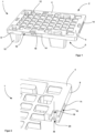
- Figure 7 shows a perspective bottom view of the sectional view from Figure 6 .
- projection 32 is passed through the second through-opening 20 and is arranged protruding therefrom.
- tab-like element 24 is positioned in the inner volume 16.
- the tab-like element 24 forms a common contact surface together with the inner base wall 26. This simultaneously closes the opening of the elongated slot 14 (not shown here).
- the tab-like element 24 is thus arranged in a stepped manner. This special stepped shape allows for a particularly stable and effective fastening.
- the projection 32 as in Figure 4 shown provided with temporal projections, which after the projection 32 has been passed through the second through-opening 20 engages underneath it and thus represents an additional security.
- Figure 8 shows a further embodiment of the flat, reusable storage and/or reusable transport device made of plastic 100.
- This also has a support element two, which has a goods carrier top 1044 and a carrier bottom 1066. Both sides are permanently connected to each other by the circumferential edge 108.
- This embodiment also advantageously has four feet 110.
- the flat reusable storage and/or reusable transport device made of plastic 100 shown here differs from the flat reusable storage and/or reusable transport device made of plastic 1 Figure 1 in that the first through-opening 118 is offset by 90° relative to the first through-opening 18 of Figure 1 is trained.
- the first through-opening 118 is rectangular. It allows passage from above into the free interior volume 116.
- the free interior volume 116 is also accessible from the side via the elongated slot 114.
- this further embodiment shows four first through-openings 118.
- Figure 9 shows an enlarged section of Figure 8
- the geometry of the second through-opening 120 remains unchanged.
- both through-openings 118, 120 also have a common center axis.
- FIG 10 A further side wall 122 is shown.
- This side wall 122 has, as an example, three tab-like elements 124 on its lower edges.
- the tab-like element 124 shown is designed to be rotated. More precisely, the projection 132 is designed to be offset by 90°. The projection 132 is designed to extend laterally here.
- the Figure 10 The tab-like element 124 shown has a first section 128 and a second section 130. However, the two sections 128 and 130 are not of the same size and symmetrical to each other, as in Figure 4 is the case. In the Figure 10 In the embodiment shown, the sections 128 and 130 are of different sizes.
- the projection has lateral extensions 133, which in the later attachment are advantageous.
- both projections 133 are formed symmetrically to each other.
- pivot axis S is also offset by 90°. This is advantageous because it provides an additional, secure fastening mechanism for the side wall 122 with the flat, reusable storage and/or reusable transport device made of plastic 100.
- Figure 11 now shows a fastening mechanism for the flat, reusable storage and/or transport device made of plastic 100 with a side wall 122.
- the properties described above also apply to this embodiment.
- the tab-like element 124 is inserted into the interior volume 116 via the elongated slot 114.
- the projection 132 is initially shown in the undeflected position. If the projection 132 is now subjected to a compressive force exerted on the projection 132 through the first through-opening 118, the projection 132 pivots downward along the pivot axis S through the second through-opening 120. Due to the advantageous extensions 133, it is possible for the projection 132 as a whole to engage beneath the underside 106 of the support. This allows for further secure fastening. When the compressive force is applied to the projection 132, the entire side wall 122 is guided downward toward the inner base wall 126 until a common contact surface is formed. At the same time, the elongated slot 114 is closed by the side wall 122.
Landscapes
- Engineering & Computer Science (AREA)
- Mechanical Engineering (AREA)
- Pallets (AREA)
Applications Claiming Priority (1)
| Application Number | Priority Date | Filing Date | Title |
|---|---|---|---|
| DE102023134862.0A DE102023134862A1 (de) | 2023-12-12 | 2023-12-12 | Flächig ausgebildete Mehrweglager- und/oder Mehrwegtransportvorrichtung aus Kunststoff zur Warenpräsentation und deren Verwendung |
Publications (1)
| Publication Number | Publication Date |
|---|---|
| EP4570688A1 true EP4570688A1 (fr) | 2025-06-18 |
Family
ID=93853072
Family Applications (1)
| Application Number | Title | Priority Date | Filing Date |
|---|---|---|---|
| EP24218581.7A Pending EP4570688A1 (fr) | 2023-12-12 | 2024-12-10 | Dispositif de stockage et/ou de transport en plastique pour la présentation de marchandises, son utilisation et procédé associé |
Country Status (2)
| Country | Link |
|---|---|
| EP (1) | EP4570688A1 (fr) |
| DE (1) | DE102023134862A1 (fr) |
Citations (5)
| Publication number | Priority date | Publication date | Assignee | Title |
|---|---|---|---|---|
| EP2878550A1 (fr) * | 2011-02-11 | 2015-06-03 | PAKI Logistics GmbH | Palette |
| US20210147111A1 (en) * | 2018-04-17 | 2021-05-20 | Chep Technology Pty Limited | Pallet |
| CN215514632U (zh) * | 2021-06-01 | 2022-01-14 | 江苏轩盛塑业科技有限公司 | 一种多功能塑料托盘 |
| EP4032821A1 (fr) * | 2021-01-21 | 2022-07-27 | Eurodisplay Design In Progress Srl | Palette, superstructure et ensemble pour la manutention de marchandises |
| EP4046548A1 (fr) * | 2021-02-18 | 2022-08-24 | Hansjochen Geugelin | Fixation de quarts de palette à un socle de présentation |
Family Cites Families (2)
| Publication number | Priority date | Publication date | Assignee | Title |
|---|---|---|---|---|
| DE9104762U1 (de) * | 1991-04-18 | 1992-08-13 | Schröter + Bake AG, 8402 Neutraubling | Bausatz für einen Warenbehälter |
| GB2504087A (en) * | 2012-07-16 | 2014-01-22 | Chep Uk Ltd | Pallet with feet which nest when stacking |
-
2023
- 2023-12-12 DE DE102023134862.0A patent/DE102023134862A1/de active Pending
-
2024
- 2024-12-10 EP EP24218581.7A patent/EP4570688A1/fr active Pending
Patent Citations (5)
| Publication number | Priority date | Publication date | Assignee | Title |
|---|---|---|---|---|
| EP2878550A1 (fr) * | 2011-02-11 | 2015-06-03 | PAKI Logistics GmbH | Palette |
| US20210147111A1 (en) * | 2018-04-17 | 2021-05-20 | Chep Technology Pty Limited | Pallet |
| EP4032821A1 (fr) * | 2021-01-21 | 2022-07-27 | Eurodisplay Design In Progress Srl | Palette, superstructure et ensemble pour la manutention de marchandises |
| EP4046548A1 (fr) * | 2021-02-18 | 2022-08-24 | Hansjochen Geugelin | Fixation de quarts de palette à un socle de présentation |
| CN215514632U (zh) * | 2021-06-01 | 2022-01-14 | 江苏轩盛塑业科技有限公司 | 一种多功能塑料托盘 |
Also Published As
| Publication number | Publication date |
|---|---|
| DE102023134862A1 (de) | 2025-06-12 |
Similar Documents
| Publication | Publication Date | Title |
|---|---|---|
| DE3824984C2 (de) | Regalboden-Tragsystem mit einem Tragpfosten mit dreieckförmigem Querschnitt | |
| DE1805523C3 (de) | Trageinrichtung für Fachboden od.dgl. mit einem Tragarm | |
| DE602004005281T2 (de) | Moduläres Regal | |
| DE2448580C2 (de) | Gelaender | |
| EP3636558A1 (fr) | Palette | |
| EP4039131A1 (fr) | Système de rayonnage | |
| EP3294502B1 (fr) | Contenant de rangement | |
| WO2011058489A1 (fr) | Insert pour conteneur de transport en matière plastique | |
| WO2010028636A2 (fr) | Conteneur pouvant être constitué de plusieurs éléments latéraux et d'un panneau de fond et paroi de séparation insérable dans ce conteneur | |
| EP3865716A1 (fr) | Clip destiné à la liaison libérable des composants | |
| EP4570688A1 (fr) | Dispositif de stockage et/ou de transport en plastique pour la présentation de marchandises, son utilisation et procédé associé | |
| DE102005047187B4 (de) | Chirurgisches Befestigungselement für ein chirurgisches Profilelement eines chirurgischen Behälters, Profilelement, Satz solcher Befestigungs- oder Profilelemente, Behälter | |
| DE2116895A1 (de) | Transportkasten für Probenfläschchen | |
| DE1554472B1 (de) | Vorrichtung an Regalen od.dgl. zum leicht loesbaren Verbinden eines Pfostens mit einem Tragstueck | |
| EP4570689A1 (fr) | Dispositif de stockage et/ou de transport en plastique pour la présentation de marchandises, son utilisation et procédé associé | |
| EP0099540B1 (fr) | Support pliable pour boîte d'étalage | |
| EP4570686A1 (fr) | Dispositif de stockage et/ou de transport en plastique pour la présentation de marchandises, son utilisation et procédé associé | |
| DE4224217C2 (de) | Behälter | |
| DE1554472C (de) | Vorrichtung an Regalen oder dgl zum leicht losbaren Verbinden eines Pfostens mit einem Tragstuck | |
| EP4407136A1 (fr) | Raccord d'angle avec élément d'expansion | |
| EP0792606A2 (fr) | Etagère | |
| DE202005015415U1 (de) | Chirurgisches Befestigungselement für ein chirurgisches Profilelement eines chirurgischen Behälters | |
| DE29712455U1 (de) | Regal | |
| DE102022110515A1 (de) | Warenregal | |
| DE19755846C2 (de) | Stapelvorrichtung zur Aufnahme von mit einem Radialschlitz versehenen ringförmigen Teilen |
Legal Events
| Date | Code | Title | Description |
|---|---|---|---|
| PUAI | Public reference made under article 153(3) epc to a published international application that has entered the european phase |
Free format text: ORIGINAL CODE: 0009012 |
|
| STAA | Information on the status of an ep patent application or granted ep patent |
Free format text: STATUS: THE APPLICATION HAS BEEN PUBLISHED |
|
| AK | Designated contracting states |
Kind code of ref document: A1 Designated state(s): AL AT BE BG CH CY CZ DE DK EE ES FI FR GB GR HR HU IE IS IT LI LT LU LV MC ME MK MT NL NO PL PT RO RS SE SI SK SM TR |
|
| STAA | Information on the status of an ep patent application or granted ep patent |
Free format text: STATUS: THE APPLICATION IS DEEMED TO BE WITHDRAWN |