EP4571405A1 - Affichage avec caméra intégrée - Google Patents
Affichage avec caméra intégrée Download PDFInfo
- Publication number
- EP4571405A1 EP4571405A1 EP23465573.6A EP23465573A EP4571405A1 EP 4571405 A1 EP4571405 A1 EP 4571405A1 EP 23465573 A EP23465573 A EP 23465573A EP 4571405 A1 EP4571405 A1 EP 4571405A1
- Authority
- EP
- European Patent Office
- Prior art keywords
- camera
- lcd panel
- display
- backlight unit
- light
- Prior art date
- Legal status (The legal status is an assumption and is not a legal conclusion. Google has not performed a legal analysis and makes no representation as to the accuracy of the status listed.)
- Pending
Links
Images

Classifications
-
- G—PHYSICS
- G02—OPTICS
- G02F—OPTICAL DEVICES OR ARRANGEMENTS FOR THE CONTROL OF LIGHT BY MODIFICATION OF THE OPTICAL PROPERTIES OF THE MEDIA OF THE ELEMENTS INVOLVED THEREIN; NON-LINEAR OPTICS; FREQUENCY-CHANGING OF LIGHT; OPTICAL LOGIC ELEMENTS; OPTICAL ANALOGUE/DIGITAL CONVERTERS
- G02F1/00—Devices or arrangements for the control of the intensity, colour, phase, polarisation or direction of light arriving from an independent light source, e.g. switching, gating or modulating; Non-linear optics
- G02F1/01—Devices or arrangements for the control of the intensity, colour, phase, polarisation or direction of light arriving from an independent light source, e.g. switching, gating or modulating; Non-linear optics for the control of the intensity, phase, polarisation or colour
- G02F1/13—Devices or arrangements for the control of the intensity, colour, phase, polarisation or direction of light arriving from an independent light source, e.g. switching, gating or modulating; Non-linear optics for the control of the intensity, phase, polarisation or colour based on liquid crystals, e.g. single liquid crystal display cells
- G02F1/133—Constructional arrangements; Operation of liquid crystal cells; Circuit arrangements
- G02F1/1333—Constructional arrangements; Manufacturing methods
- G02F1/1335—Structural association of cells with optical devices, e.g. polarisers or reflectors
-
- G—PHYSICS
- G02—OPTICS
- G02F—OPTICAL DEVICES OR ARRANGEMENTS FOR THE CONTROL OF LIGHT BY MODIFICATION OF THE OPTICAL PROPERTIES OF THE MEDIA OF THE ELEMENTS INVOLVED THEREIN; NON-LINEAR OPTICS; FREQUENCY-CHANGING OF LIGHT; OPTICAL LOGIC ELEMENTS; OPTICAL ANALOGUE/DIGITAL CONVERTERS
- G02F1/00—Devices or arrangements for the control of the intensity, colour, phase, polarisation or direction of light arriving from an independent light source, e.g. switching, gating or modulating; Non-linear optics
- G02F1/01—Devices or arrangements for the control of the intensity, colour, phase, polarisation or direction of light arriving from an independent light source, e.g. switching, gating or modulating; Non-linear optics for the control of the intensity, phase, polarisation or colour
- G02F1/13—Devices or arrangements for the control of the intensity, colour, phase, polarisation or direction of light arriving from an independent light source, e.g. switching, gating or modulating; Non-linear optics for the control of the intensity, phase, polarisation or colour based on liquid crystals, e.g. single liquid crystal display cells
- G02F1/133—Constructional arrangements; Operation of liquid crystal cells; Circuit arrangements
- G02F1/13306—Circuit arrangements or driving methods for the control of single liquid crystal cells
- G02F1/13312—Circuits comprising photodetectors for purposes other than feedback
-
- B—PERFORMING OPERATIONS; TRANSPORTING
- B60—VEHICLES IN GENERAL
- B60R—VEHICLES, VEHICLE FITTINGS, OR VEHICLE PARTS, NOT OTHERWISE PROVIDED FOR
- B60R1/00—Optical viewing arrangements; Real-time viewing arrangements for drivers or passengers using optical image capturing systems, e.g. cameras or video systems specially adapted for use in or on vehicles
- B60R1/20—Real-time viewing arrangements for drivers or passengers using optical image capturing systems, e.g. cameras or video systems specially adapted for use in or on vehicles
- B60R1/30—Real-time viewing arrangements for drivers or passengers using optical image capturing systems, e.g. cameras or video systems specially adapted for use in or on vehicles providing vision in the non-visible spectrum, e.g. night or infrared vision
-
- G—PHYSICS
- G02—OPTICS
- G02B—OPTICAL ELEMENTS, SYSTEMS OR APPARATUS
- G02B6/00—Light guides; Structural details of arrangements comprising light guides and other optical elements, e.g. couplings
- G02B6/0001—Light guides; Structural details of arrangements comprising light guides and other optical elements, e.g. couplings specially adapted for lighting devices or systems
- G02B6/0011—Light guides; Structural details of arrangements comprising light guides and other optical elements, e.g. couplings specially adapted for lighting devices or systems the light guides being planar or of plate-like form
- G02B6/0033—Means for improving the coupling-out of light from the light guide
- G02B6/005—Means for improving the coupling-out of light from the light guide provided by one optical element, or plurality thereof, placed on the light output side of the light guide
- G02B6/0053—Prismatic sheet or layer; Brightness enhancement element, sheet or layer
-
- G—PHYSICS
- G02—OPTICS
- G02B—OPTICAL ELEMENTS, SYSTEMS OR APPARATUS
- G02B6/00—Light guides; Structural details of arrangements comprising light guides and other optical elements, e.g. couplings
- G02B6/10—Light guides; Structural details of arrangements comprising light guides and other optical elements, e.g. couplings of the optical waveguide type
- G02B6/12—Light guides; Structural details of arrangements comprising light guides and other optical elements, e.g. couplings of the optical waveguide type of the integrated circuit kind
- G02B6/122—Basic optical elements, e.g. light-guiding paths
-
- G—PHYSICS
- G02—OPTICS
- G02F—OPTICAL DEVICES OR ARRANGEMENTS FOR THE CONTROL OF LIGHT BY MODIFICATION OF THE OPTICAL PROPERTIES OF THE MEDIA OF THE ELEMENTS INVOLVED THEREIN; NON-LINEAR OPTICS; FREQUENCY-CHANGING OF LIGHT; OPTICAL LOGIC ELEMENTS; OPTICAL ANALOGUE/DIGITAL CONVERTERS
- G02F1/00—Devices or arrangements for the control of the intensity, colour, phase, polarisation or direction of light arriving from an independent light source, e.g. switching, gating or modulating; Non-linear optics
- G02F1/01—Devices or arrangements for the control of the intensity, colour, phase, polarisation or direction of light arriving from an independent light source, e.g. switching, gating or modulating; Non-linear optics for the control of the intensity, phase, polarisation or colour
- G02F1/13—Devices or arrangements for the control of the intensity, colour, phase, polarisation or direction of light arriving from an independent light source, e.g. switching, gating or modulating; Non-linear optics for the control of the intensity, phase, polarisation or colour based on liquid crystals, e.g. single liquid crystal display cells
- G02F1/133—Constructional arrangements; Operation of liquid crystal cells; Circuit arrangements
- G02F1/1333—Constructional arrangements; Manufacturing methods
- G02F1/133308—Support structures for LCD panels, e.g. frames or bezels
- G02F1/133331—Cover glasses
-
- G—PHYSICS
- G02—OPTICS
- G02F—OPTICAL DEVICES OR ARRANGEMENTS FOR THE CONTROL OF LIGHT BY MODIFICATION OF THE OPTICAL PROPERTIES OF THE MEDIA OF THE ELEMENTS INVOLVED THEREIN; NON-LINEAR OPTICS; FREQUENCY-CHANGING OF LIGHT; OPTICAL LOGIC ELEMENTS; OPTICAL ANALOGUE/DIGITAL CONVERTERS
- G02F1/00—Devices or arrangements for the control of the intensity, colour, phase, polarisation or direction of light arriving from an independent light source, e.g. switching, gating or modulating; Non-linear optics
- G02F1/01—Devices or arrangements for the control of the intensity, colour, phase, polarisation or direction of light arriving from an independent light source, e.g. switching, gating or modulating; Non-linear optics for the control of the intensity, phase, polarisation or colour
- G02F1/13—Devices or arrangements for the control of the intensity, colour, phase, polarisation or direction of light arriving from an independent light source, e.g. switching, gating or modulating; Non-linear optics for the control of the intensity, phase, polarisation or colour based on liquid crystals, e.g. single liquid crystal display cells
- G02F1/133—Constructional arrangements; Operation of liquid crystal cells; Circuit arrangements
- G02F1/1333—Constructional arrangements; Manufacturing methods
- G02F1/1335—Structural association of cells with optical devices, e.g. polarisers or reflectors
- G02F1/1336—Illuminating devices
-
- G—PHYSICS
- G06—COMPUTING OR CALCULATING; COUNTING
- G06F—ELECTRIC DIGITAL DATA PROCESSING
- G06F1/00—Details not covered by groups G06F3/00 - G06F13/00 and G06F21/00
- G06F1/16—Constructional details or arrangements
- G06F1/1601—Constructional details related to the housing of computer displays, e.g. of CRT monitors, of flat displays
- G06F1/1605—Multimedia displays, e.g. with integrated or attached speakers, cameras, microphones
-
- G—PHYSICS
- G09—EDUCATION; CRYPTOGRAPHY; DISPLAY; ADVERTISING; SEALS
- G09F—DISPLAYING; ADVERTISING; SIGNS; LABELS OR NAME-PLATES; SEALS
- G09F9/00—Indicating arrangements for variable information in which the information is built-up on a support by selection or combination of individual elements
- G09F9/30—Indicating arrangements for variable information in which the information is built-up on a support by selection or combination of individual elements in which the desired character or characters are formed by combining individual elements
- G09F9/33—Indicating arrangements for variable information in which the information is built-up on a support by selection or combination of individual elements in which the desired character or characters are formed by combining individual elements being semiconductor devices, e.g. diodes
-
- H—ELECTRICITY
- H04—ELECTRIC COMMUNICATION TECHNIQUE
- H04N—PICTORIAL COMMUNICATION, e.g. TELEVISION
- H04N23/00—Cameras or camera modules comprising electronic image sensors; Control thereof
- H04N23/20—Cameras or camera modules comprising electronic image sensors; Control thereof for generating image signals from infrared radiation only
-
- H—ELECTRICITY
- H04—ELECTRIC COMMUNICATION TECHNIQUE
- H04N—PICTORIAL COMMUNICATION, e.g. TELEVISION
- H04N23/00—Cameras or camera modules comprising electronic image sensors; Control thereof
- H04N23/57—Mechanical or electrical details of cameras or camera modules specially adapted for being embedded in other devices
-
- G—PHYSICS
- G02—OPTICS
- G02B—OPTICAL ELEMENTS, SYSTEMS OR APPARATUS
- G02B6/00—Light guides; Structural details of arrangements comprising light guides and other optical elements, e.g. couplings
- G02B6/0001—Light guides; Structural details of arrangements comprising light guides and other optical elements, e.g. couplings specially adapted for lighting devices or systems
- G02B6/0011—Light guides; Structural details of arrangements comprising light guides and other optical elements, e.g. couplings specially adapted for lighting devices or systems the light guides being planar or of plate-like form
- G02B6/0033—Means for improving the coupling-out of light from the light guide
- G02B6/0035—Means for improving the coupling-out of light from the light guide provided on the surface of the light guide or in the bulk of it
- G02B6/0036—2-D arrangement of prisms, protrusions, indentations or roughened surfaces
-
- G—PHYSICS
- G02—OPTICS
- G02F—OPTICAL DEVICES OR ARRANGEMENTS FOR THE CONTROL OF LIGHT BY MODIFICATION OF THE OPTICAL PROPERTIES OF THE MEDIA OF THE ELEMENTS INVOLVED THEREIN; NON-LINEAR OPTICS; FREQUENCY-CHANGING OF LIGHT; OPTICAL LOGIC ELEMENTS; OPTICAL ANALOGUE/DIGITAL CONVERTERS
- G02F1/00—Devices or arrangements for the control of the intensity, colour, phase, polarisation or direction of light arriving from an independent light source, e.g. switching, gating or modulating; Non-linear optics
- G02F1/01—Devices or arrangements for the control of the intensity, colour, phase, polarisation or direction of light arriving from an independent light source, e.g. switching, gating or modulating; Non-linear optics for the control of the intensity, phase, polarisation or colour
- G02F1/13—Devices or arrangements for the control of the intensity, colour, phase, polarisation or direction of light arriving from an independent light source, e.g. switching, gating or modulating; Non-linear optics for the control of the intensity, phase, polarisation or colour based on liquid crystals, e.g. single liquid crystal display cells
- G02F1/133—Constructional arrangements; Operation of liquid crystal cells; Circuit arrangements
- G02F1/1333—Constructional arrangements; Manufacturing methods
- G02F1/1335—Structural association of cells with optical devices, e.g. polarisers or reflectors
- G02F1/1336—Illuminating devices
- G02F1/133615—Edge-illuminating devices, i.e. illuminating from the side
-
- G—PHYSICS
- G02—OPTICS
- G02F—OPTICAL DEVICES OR ARRANGEMENTS FOR THE CONTROL OF LIGHT BY MODIFICATION OF THE OPTICAL PROPERTIES OF THE MEDIA OF THE ELEMENTS INVOLVED THEREIN; NON-LINEAR OPTICS; FREQUENCY-CHANGING OF LIGHT; OPTICAL LOGIC ELEMENTS; OPTICAL ANALOGUE/DIGITAL CONVERTERS
- G02F2203/00—Function characteristic
- G02F2203/11—Function characteristic involving infrared radiation
-
- G—PHYSICS
- G06—COMPUTING OR CALCULATING; COUNTING
- G06F—ELECTRIC DIGITAL DATA PROCESSING
- G06F1/00—Details not covered by groups G06F3/00 - G06F13/00 and G06F21/00
- G06F1/16—Constructional details or arrangements
- G06F1/1613—Constructional details or arrangements for portable computers
- G06F1/1633—Constructional details or arrangements of portable computers not specific to the type of enclosures covered by groups G06F1/1615 - G06F1/1626
- G06F1/1637—Details related to the display arrangement, including those related to the mounting of the display in the housing
-
- G—PHYSICS
- G06—COMPUTING OR CALCULATING; COUNTING
- G06F—ELECTRIC DIGITAL DATA PROCESSING
- G06F1/00—Details not covered by groups G06F3/00 - G06F13/00 and G06F21/00
- G06F1/16—Constructional details or arrangements
- G06F1/1613—Constructional details or arrangements for portable computers
- G06F1/1633—Constructional details or arrangements of portable computers not specific to the type of enclosures covered by groups G06F1/1615 - G06F1/1626
- G06F1/1684—Constructional details or arrangements related to integrated I/O peripherals not covered by groups G06F1/1635 - G06F1/1675
- G06F1/1686—Constructional details or arrangements related to integrated I/O peripherals not covered by groups G06F1/1635 - G06F1/1675 the I/O peripheral being an integrated camera
-
- H—ELECTRICITY
- H04—ELECTRIC COMMUNICATION TECHNIQUE
- H04M—TELEPHONIC COMMUNICATION
- H04M1/00—Substation equipment, e.g. for use by subscribers
- H04M1/02—Constructional features of telephone sets
- H04M1/0202—Portable telephone sets, e.g. cordless phones, mobile phones or bar type handsets
- H04M1/026—Details of the structure or mounting of specific components
- H04M1/0264—Details of the structure or mounting of specific components for a camera module assembly
Definitions
- the invention relates to a display with integrated camera and a vehicle with such integrated display.
- OEMs Original Equipment Manufacturer
- This type of approach can be found in consumer products such as smartphones, tablets, and laptops, currently raising the interest for automotive products also.
- the technology used to integrate the camera behind a display is mainly influenced by the display type technology, such as LCD (LCD: Liquid Cristal Display) display and LED (LED: Light-Emitting Diode) display.
- LCD LCD: Liquid Cristal Display
- LED LED Light-Emitting Diode
- Smartphone manufacturers addressed this problem by firstly creating a notch within the display and installing the camera within the notch behind a cover glass of the display.
- such camera installed in the notch cannot be regarded as seamless integrated and as a camera behind a display.
- EP 4 102 810 A1 and US 11 145 233 B1 describe the usage of a lower pixel density and/or of smaller pixels, for an active area of the camera.
- such approaches propose a lower pixel density and/or smaller pixels for the area where the camera captures the image to create enough space for the light to enter.
- Different pixel arrangements are also possible for such approaches, as this aspect can also have an effect for the quality of the picture.
- US 2020/0117034 A1 describes a camera installed behind an LCD display in a through hole.
- the LCD display comprises a cover glass, an optically clear adhesive (OCA: optically clear adhesive) layer, a first polarizer, a first glass substrate, a color film (CF: color film) layer, a thin film transistor (TFT: thin film transistor) layer, a second glass substrate, a second polarizer, and a backlight module.
- OCA optically clear adhesive
- the through hole is provided through the first polarizer, the CF layer, the TFT layer, the second polarizer, and the backlight module.
- the through hole forms a light channel in the LCD for ambient light coming from outside of the electronic device, passing through the cover glass and the light channel, and entering into the camera.
- the camera is disposed in whole or in part inside the through hole.
- the first glass substrate and the second glass substrate are not hollowed out in a region corresponding to the light channel.
- Such an approach requires a great deal of effort to align such a through hole in almost all parts of an LCD.
- drilling such through hole in nearly all parts of the LCD can result in damages in each single part of the LCD.
- the parts must be controlled for damages and a correct alignment with regard to the through hole. All the afore mentioned in turn leads to higher costs.
- WO 2021/258921 A1 describes a camera device under a display screen.
- the display comprises a display screen and a camera.
- the display screen includes a cover at the top and a display module under the cover.
- the display module includes an ITO (ITO: Indium Tin Oxide) glass, a liquid crystal layer and a backlight layer.
- ITO Indium Tin Oxide
- the display screen is provided with a blind hole area, which blind hole area is formed on the liquid crystal layer above an opening that goes through the whole backlight layer.
- the camera is arranged directly below the blind hole and a lens of the camera extends into the hole in the backlight layer onto the blind hole area, forming an angle of view through the blind hole.
- the display screen further includes an electric field circuit, which is provided on the ITO glass layer of the outermost layer of the liquid crystal layer, and which electric field circuit drives the deflection of the liquid crystal in the blind hole area of the display screen through the change of the electric field, so as to change the optical path of the light passing through the blind hole area, and to realize the focusing of the camera.
- an electric field circuit which is provided on the ITO glass layer of the outermost layer of the liquid crystal layer, and which electric field circuit drives the deflection of the liquid crystal in the blind hole area of the display screen through the change of the electric field, so as to change the optical path of the light passing through the blind hole area, and to realize the focusing of the camera.
- LCD panels are composed of a liquid crystal layer sandwiched between two electrodes, together with the polarizers that are optical filters that transmit light of a particular polarization.
- polarizers that are optical filters that transmit light of a particular polarization.
- common LCD panels have two polarizers, one for each side. When light passes through an LCD panel and polarizer, it is partially absorbed and scattered, which reduces the amount of light that reaches a camera sensor behind a display. This can lead to decreased image quality and reduced camera performance, thus an increased amount of hardware compensation is needed.
- US 2022/0179452 A1 describes electronic devices including a front-facing camera disposed behind a front-facing display.
- Such device described in US 2022/0179452 A1 comprises a display having a front surface and a back surface, the display including a plurality of pixel regions that emit light from the front surface of the display to display a displayed image and a plurality of apertures that transmit light from the front surface to the back surface.
- a camera is disposed on a side of the back surface of the display. The camera is configured to capture images.
- the device further includes restoration optics disposed between the display and the camera, which restoration optics are configured to reduce image distortion caused by the display.
- the restoration optics may include an optical filter (e.g., a phase-shift mask), a bandpass filter, a lens that includes a varifocal lens and/or different and/or additional components. It is further described that various items of the restoration optics can be included in the camera and therefore excluded from the restoration optics.
- a processor is coupled to the display and the camera, which processor is configured to apply a digital filter to at least a portion of the captured image to further reduce the image distortion caused by the display. Accordingly, the image distortion caused by the display is reduced both physically, by the restoration optics and digitally by the processor.
- a complex setup is described in US 2022/0179452 A1 that needs both physically and digitally reduction of image distortion caused by the display. However, such approach also leads to high efforts and results in high costs.
- WO 2009/051673 A1 describes an image capture device, working in the visible spectrum, being placed behind a switchable diffuser and either behind a light guide or in a hole or opening within the light guide behind a display.
- the switchable diffuser is arranged in front of the light guide.
- WO 2009/051673 A1 further describes that a light guide typically has scattering elements, also referred to as scattering dots, on the backside of the light guide plate to scatter light that has been conducted from the backlight bulbs into the light guide plate, toward the front side of the LCD display assembly.
- Such scattering elements are also known from the state of the art as dot structures, microdots or microlenses, provided at a surface of the light guide, typically the backside of the light guide, used as described in WO 2009/051673 A1 to guide light towards the display panel.
- the amount of resulting light is defined by the density of a dot structure, microdot or microlens population. The higher the density, the more light will leave the light guide at its desired area. However, smaller densities are limited, as single microdots or microlenses will not produce homogeneous light output.
- the microdots or microlenses are imprinted or injection molded microdots of hemisphere-like shape with spherical caps provided on a surface on the backside or a frontside of the light guide plate.
- the diameter of the spherical caps or rather the microdots or microlenses have a size of around tens of micrometers.
- WO 2009/051673 A1 further describes the importance of the usage of the switchable diffuser to be able to capture sufficient light for the image capture device, to improve the uniformity of the light going through the LCD panel and to make the scattering elements less visible from a front side of the LCD.
- WO 2009/051673 A1 therefore proposes a control logic for the LCD panel, camera and diffuser, to permit sufficient light to be captured by the camera.
- the solution known from WO 2009/051673 A1 needs an increased amount of logic and Hardware to perform all the mandatory steps in order to capture the image.
- an apparatus comprises a display device and a camera.
- the display device comprises a cover glass, an LCD Panel, and a backlight unit.
- the LCD Panel is arranged behind the cover glass
- the backlight unit is arranged behind the LCD Panel
- the camera is arranged behind the backlight unit with its field of view directed to the backlight unit, more precisely to a light guide of the backlight unit further described below.
- the cover glass is the part of the display that is closest to a user looking at the display.
- behind the cover glass means that the respective component behind the cover glass, in this case the LCD panel, is arranged on an opposite side of the display glass than the side of the display glass that a user is looking at when looking at the display.
- the field of view of the camera defines an active area of the camera.
- the field of view and therefore the active area of the camera is larger if, for example, a wide-angle lens is used and/or the further away the camera is placed from the backlight unit. It is also understood that, conversely, the field of view and therefore the active area of the camera is smaller if, for example, a telephoto lens is used and/or the closer the camera is moved to the backlight unit.
- the backlight unit comprises an edge light source and a light guide.
- the camera operates in the infrared wavelength spectrum.
- the advantage of the usage of a camera which operates in the infrared wavelength spectrum is that the IR light transmission is not or only weakly affected by the LCD panel and its polarizers.
- the term "operates in the infrared wavelength spectrum” means that the camera or rather an image capture element of the camera is at least sensitive to the infrared spectrum and at least captures images in the IR-spectrum (IR: infrared). It is understood that the camera can either be only operatable in the IR-spectrum, i.e., be arranged as an IR-Camera, or in addition to operating in the IR-spectrum also operating in the visible wavelength spectrum.
- the light guide is a light guide with nanostructures. It has been found that a light guide with nanostructures does not affect infrared light when compared to a light guide with microstructures. Hence, a light guide with nanostructures is suitable to be used with cameras operating in the IR wavelength spectrum, with no further processing needed.
- a surface of the light guide can be provided with such nanostructures at a backside or a frontside of the light guide. However, when applied to the backside surface, such structures become less visible.
- nanostructures mean that the structures, e.g., spherical caps at a surface of the light guide, have sizes smaller than 1 ⁇ m with regard to their diameter or rather its largest extent in one dimension.
- the structures have sizes between 1 nm and 1 ⁇ m.
- the term “nanostructures” means that the structures, e.g., spherical caps at a surface of the light guide in the camera window, have sizes smaller than 1 ⁇ m with regard to their diameter or rather its largest extent in one dimension.
- the structures have sizes between 1 nm and 1 ⁇ m.
- the structures have sizes between 100 nm and 990 nm.
- the form, size and density of the elements i.e., the density per a given area, can be individually chosen depending on the used light guide and the technical requirements of the whole apparatus, e.g., the display.
- the form of such nanostructure can be similar to a pyramid, a cone, a frustum and/or a cylinder instead of spherical caps. It is understood that the invention is not limited to the afore-mentioned forms of structures and that there exist plenty further forms that can be used for those structures.
- the present invention proposes a simple solution to obtain a seamless integration of a camera, e.g., a driver monitoring module, in a display, with no effect on the displayed content.
- the present solution removes the need for a switchable diffuser and increased logic to control it, given that the camera can capture an image only when the diffuser is set to "clear" state and the LCD panel to "transparent” state.
- the solution further removes the need of a through hole through parts of the LCD panel, the whole backlight unit and or the need to drive the deflection of the liquid crystal in a blind hole area of the display screen through the change of an applied electric field, to change the optical path of the light passing through the blind hole area, and to realize the focusing of the camera.
- the solution there is no necessity of a physical reduction of an image distortion caused by the display, e.g., by using restoration optics.
- the proposed solution can accommodate the camera in any location of the LCD panel, given the fact that the solution can use any commercially available LCD screen with no additional processing needed.
- the proposed seamless integration of the camera behind the display provides an enhancement in user experience, yet with additional functionalities for the device.
- the cover glass is optically bonded to the LCD Panel.
- the optical bonding is clear and it is understood that the cover glass and optical bonding material are transparent and do not affect the behavior of a captured image.
- the backlight unit further comprises a light enhancement layer.
- the light enhancement layer (4) comprises a cut-out window in the active area of the camera. It is understood that the light enhancement layer is arranged such that the light guide is arranged behind the light enhancement layer.
- the light enhancement layer may comprise one or more foils.
- the cut-out window preferably is identical to the size of the active area. However, the cut-out window may be smaller than the size of the active area. This has the advantage that the cut-out window has less disturbing visible effect to the user watching at the display, e.g, a driver. Alternatively, the cut-out window may be larger than the size of the active area. This has the advantage that no negative influence of the light enhancement layer appears in the camera image.
- cut-out window in the light enhancement layer means that there is an area in the light enhancement layer defined by the active area of the camera, where the light enhancement layer is modified, for example there is a hole in a part of the light enhancement layer, and through which modified area the camera can look through in an undisturbed manner.
- the light enhancement layer is formed by a stack of foils comprising a Louver foil and/or a reflective polarizing foil and/or a diffusing foil at least one of which comprises the cut-out window. It is understood that dependent on the respective foil's properties, it can be sufficient if only one of the foils of the stack of foils comprises a cut-out window. For example, several foils of such stack of foils may not have or have only little effect on IR-light. The usage of a foil stack with foils having different properties has the advantage that the optical performance of such apparatus can be enhanced dependent on the technical requirements of the apparatus, e.g., the display.
- the apparatus comprises a processor, the processor is provided to apply a post-processing algorithm, preferably a deconvolution algorithm, on a captured image taken by the camera.
- the post-processing algorithm enhances the quality of a captured image with regard to effects caused by the LCD panel on a captured image.
- the post-processing algorithm preferably is a deconvolution algorithm.
- further post-capture image processing methods to improve image quality of a captured image which may also advantageously used as such post-processing algorithm.
- the size of the cut-out window is smaller than the active area.
- the camera is detecting image information of a first area within the cut-out window and of a second area outside the cut-out window.
- the detected image information from both areas is provided to the post-processing algorithm.
- Such embodiment advantageously provides information to calibrate the post-processing algorithm.
- the LCD Panel comprises two polarizers at least one of which does not influence or only weakly influence IR light passing the respective polarizer.
- Such embodiment improves light yield in the IR-spectrum with the camera behind the display.
- such embodiment may comprise a special physical arrangement of the at least one polarizer which enables at least a part of IR-light to pass the at least one polarizer.
- a part of the at least one polarizer in the line of sight of the camera or the whole at least one polarizer comprises or consists of a material which enables at least a part of IR-light to pass the at least one polarizer.
- the LCD Panel (2) comprises two polarizers, both of the polarizers do not influence or only weakly influence IR light passing the polarizers.
- Such embodiment further improves light yield in the IR-spectrum with the camera behind the display.
- such embodiment may comprise a special physical arrangement of both polarizers which enables at least a part of IR-light to pass both polarizers.
- a part of each of both polarizers in the line of sight of the camera or both polarizers in a whole comprise or consist of a material which enables at least a part of IR-light to pass both polarizers.
- the liquid crystal material of the LCD panel does not influence or only weakly influence IR light passing the LCD Panel.
- Such embodiment further improves light yield in the IR-spectrum with the camera behind the display, similar as described above with regard to polarizers.
- a vehicle comprises an apparatus in accordance with at least one of the afore-mentioned embodiments.
- Such seamless integrated camera behind a display can be introduced in products that are following a user and provide an interactive experience given the orientation of the user's eyes, especially for entertainment activities.
- the camera can be introduced in the back of a Smart TV display, and through specific and compatible content, the user can have a real-time experience with his digital twin like playing different games or participating in sport classes.
- a further example is an apparatus with a seamless integrated camera behind a display that additionally comprises a motion sensor input device that enables features such as skeleton tracking, hand interactions, and voice recognition.
- Such motion sensor can track the motion of the person in front of the device and create a link between the movement and a "digital twin" shown on the display.
- such motion sensor input device is equipped with RGB cameras and infrared projectors and detectors that can perform real-time gesture recognition.
- Fig. 1 shows a schematical sketch of an apparatus in accordance with a first embodiment of the invention in a cross-sectional view.
- the apparatus comprises a display device 1 and a camera 3 operating in the infrared wavelength spectrum.
- the display device 1 comprises a cover glass 7, an LCD Panel 2 and a backlight unit.
- the cover glass 7 is optically bonded to the LCD Panel 2, which LCD Panel 2 is arranged behind the cover glass 7.
- the backlight unit comprises a light source 8 disposed at the edge of the display device 1 and a light guide 5.
- the backlight unit, especially the light guide 5, is arranged behind the LCD Panel 2.
- the light source 8 is arranged at an edge of the light guide 5.
- the light emitted by the light source 8 is coupled into the light guide at the edge of the light guide 5.
- the camera 3 is arranged behind the backlight unit with its field of view directed to the backlight unit, more precisely to the light guide 5.
- the field of view of the camera 3 defines an active area 9 of the camera 3.
- the field of view of the camera is indicated by the dotted lines starting from camera 3.
- the active area 9 expands, with greater distance to the camera 3.
- the light guide 5 comprises microstructures (not shown here).
- the light guide 5 is a light guide with nanostructures 11 (not shown here) of a hemisphere-like shape with spherical caps of diameters around 100 nm to 900 nm.
- the LCD Panel 2 comprises two polarizers (not shown here), both polarizers do not influence or only weakly influence infrared light passing the polarizers. Additionally, the liquid crystal material of the LCD panel 2 does not influence or only weakly influence Infrared light passing the LCD panel 2.
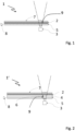
- Fig. 2 shows a schematical sketch of an apparatus in accordance with a second embodiment of the invention in a cross-sectional view.
- the apparatus shown in Fig. 2 differs from that shown in Fig. 1 in that the backlight unit of the display 1' further comprises a light enhancement layer 4 arranged in front of the light guide 5.
- the light enhancement layer 4, here formed by only one foil, comprises a cut-out window 6 in the active area 9 of the camera 3.
- Fig. 3 shows a schematical sketch of an apparatus in accordance with a third embodiment of the invention in a perspective view.
- the apparatus comprises a display device 1" and a camera 3 operating in the infrared wavelength spectrum as in Fig. 2 .
- the cover glass 7 is omitted in this figure for simplicity.
- the light enhancement layer, in Fig. 3 is formed as a foil stack 4'. Only half of a nanostructured light guide 5 is shown in Fig. 3 to highlight the cut-out window 6 in the light enhancement layer, here the foil stack 4'. Only the first foil 40, which is arranged nearest to the light guide 5, comprises a cut-out window 6 in the active area of the camera 3. However, it is understood that there may be embodiments in which a cut-out window is arranged in one or more further foils of the foil stack or through the whole foil stack 4'.
- the LCD Panel 2' comprises two polarizers (not shown here) of which one does not influence or only weakly influence Infrared light passing the respective polarizer.
- the apparatus comprises a processor (not shown here), the processor is installed to apply a deconvolution algorithm on a captured image taken by the camera. Thereby, an image quality of a captured image is enhanced which is affected by the LCD panel, e.g., considering an alignment of pixels.
- This processor may be implemented as a separate device, may be integrated in a processor that also performs other tasks, may be implemented as other hardware or may also be implemented as an algorithm performed by a computing unit.
- the light guide 5 with nanostructures 11 can be seen in more detail in an exemplary symbolic form in an enlarged view of the active area 9 of the camera 3, shown in Fig. 4 .
- a user 10 here a driver in a vehicle, is looking at the display device 1" and is monitored by the camera 3 which is arranged seamless behind the display device 1" and cannot be seen from the user as he is looking at the display device 1".
- the camera 3 is thus hidden from a view of the user 10.
Landscapes
- Physics & Mathematics (AREA)
- Engineering & Computer Science (AREA)
- Nonlinear Science (AREA)
- General Physics & Mathematics (AREA)
- Multimedia (AREA)
- Optics & Photonics (AREA)
- Mathematical Physics (AREA)
- Chemical & Material Sciences (AREA)
- Crystallography & Structural Chemistry (AREA)
- Signal Processing (AREA)
- Theoretical Computer Science (AREA)
- General Engineering & Computer Science (AREA)
- Mechanical Engineering (AREA)
- Microelectronics & Electronic Packaging (AREA)
- Computer Hardware Design (AREA)
- Human Computer Interaction (AREA)
- Devices For Indicating Variable Information By Combining Individual Elements (AREA)
- Liquid Crystal (AREA)
- Fittings On The Vehicle Exterior For Carrying Loads, And Devices For Holding Or Mounting Articles (AREA)
- Studio Devices (AREA)
Priority Applications (5)
| Application Number | Priority Date | Filing Date | Title |
|---|---|---|---|
| EP23465573.6A EP4571405A1 (fr) | 2023-12-13 | 2023-12-13 | Affichage avec caméra intégrée |
| KR1020240155708A KR20250091073A (ko) | 2023-12-13 | 2024-11-05 | 카메라 일체형 디스플레이 |
| CN202411809121.0A CN120143491A (zh) | 2023-12-13 | 2024-12-10 | 集成有摄像头的显示器 |
| US18/978,821 US20250199355A1 (en) | 2023-12-13 | 2024-12-12 | Display with integrated camera |
| JP2024218177A JP2025094935A (ja) | 2023-12-13 | 2024-12-12 | カメラ一体型ディスプレイ |
Applications Claiming Priority (1)
| Application Number | Priority Date | Filing Date | Title |
|---|---|---|---|
| EP23465573.6A EP4571405A1 (fr) | 2023-12-13 | 2023-12-13 | Affichage avec caméra intégrée |
Publications (1)
| Publication Number | Publication Date |
|---|---|
| EP4571405A1 true EP4571405A1 (fr) | 2025-06-18 |
Family
ID=89843608
Family Applications (1)
| Application Number | Title | Priority Date | Filing Date |
|---|---|---|---|
| EP23465573.6A Pending EP4571405A1 (fr) | 2023-12-13 | 2023-12-13 | Affichage avec caméra intégrée |
Country Status (5)
| Country | Link |
|---|---|
| US (1) | US20250199355A1 (fr) |
| EP (1) | EP4571405A1 (fr) |
| JP (1) | JP2025094935A (fr) |
| KR (1) | KR20250091073A (fr) |
| CN (1) | CN120143491A (fr) |
Families Citing this family (1)
| Publication number | Priority date | Publication date | Assignee | Title |
|---|---|---|---|---|
| EP4571404A1 (fr) * | 2023-12-13 | 2025-06-18 | Continental Automotive Technologies GmbH | Affichage avec caméra intégrée |
Citations (7)
| Publication number | Priority date | Publication date | Assignee | Title |
|---|---|---|---|---|
| US20090102763A1 (en) * | 2007-10-19 | 2009-04-23 | Border John N | Display device with capture capabilities |
| CN108761923A (zh) * | 2018-08-10 | 2018-11-06 | Oppo广东移动通信有限公司 | 背光模组、液晶显示模组和电子装置 |
| US20200117034A1 (en) | 2017-04-25 | 2020-04-16 | Huawei Technologies Co., Ltd. | LCD Display, Electronic Device, LCD Display Manufacturing Method |
| US11145233B1 (en) | 2020-06-22 | 2021-10-12 | Motorola Mobility Llc | Masking for mitigating visual contrast of a camera region of a display |
| WO2021258921A1 (fr) | 2020-06-23 | 2021-12-30 | 中兴通讯股份有限公司 | Dispositif de caméra à écran de sous-affichage |
| US20220179452A1 (en) | 2018-09-27 | 2022-06-09 | Apple Inc. | Electronic device including a camera disposed behind a display |
| EP4102810A1 (fr) | 2020-02-05 | 2022-12-14 | Samsung Electronics Co., Ltd. | Dispositif électronique comprenant un capteur d'image |
Family Cites Families (2)
| Publication number | Priority date | Publication date | Assignee | Title |
|---|---|---|---|---|
| JP2015532724A (ja) * | 2012-08-21 | 2015-11-12 | 張大海ZHANG, Dahai | 導光板表面構造、その応用及び製造方法 |
| JP7571611B2 (ja) * | 2021-02-22 | 2024-10-23 | 日本精機株式会社 | 表示装置 |
-
2023
- 2023-12-13 EP EP23465573.6A patent/EP4571405A1/fr active Pending
-
2024
- 2024-11-05 KR KR1020240155708A patent/KR20250091073A/ko active Pending
- 2024-12-10 CN CN202411809121.0A patent/CN120143491A/zh active Pending
- 2024-12-12 JP JP2024218177A patent/JP2025094935A/ja active Pending
- 2024-12-12 US US18/978,821 patent/US20250199355A1/en active Pending
Patent Citations (8)
| Publication number | Priority date | Publication date | Assignee | Title |
|---|---|---|---|---|
| US20090102763A1 (en) * | 2007-10-19 | 2009-04-23 | Border John N | Display device with capture capabilities |
| WO2009051673A1 (fr) | 2007-10-19 | 2009-04-23 | Eastman Kodak Company | Dispositif d'affichage ayant des capacités de capture |
| US20200117034A1 (en) | 2017-04-25 | 2020-04-16 | Huawei Technologies Co., Ltd. | LCD Display, Electronic Device, LCD Display Manufacturing Method |
| CN108761923A (zh) * | 2018-08-10 | 2018-11-06 | Oppo广东移动通信有限公司 | 背光模组、液晶显示模组和电子装置 |
| US20220179452A1 (en) | 2018-09-27 | 2022-06-09 | Apple Inc. | Electronic device including a camera disposed behind a display |
| EP4102810A1 (fr) | 2020-02-05 | 2022-12-14 | Samsung Electronics Co., Ltd. | Dispositif électronique comprenant un capteur d'image |
| US11145233B1 (en) | 2020-06-22 | 2021-10-12 | Motorola Mobility Llc | Masking for mitigating visual contrast of a camera region of a display |
| WO2021258921A1 (fr) | 2020-06-23 | 2021-12-30 | 中兴通讯股份有限公司 | Dispositif de caméra à écran de sous-affichage |
Also Published As
| Publication number | Publication date |
|---|---|
| US20250199355A1 (en) | 2025-06-19 |
| KR20250091073A (ko) | 2025-06-20 |
| JP2025094935A (ja) | 2025-06-25 |
| CN120143491A (zh) | 2025-06-13 |
Similar Documents
| Publication | Publication Date | Title |
|---|---|---|
| JP6700044B2 (ja) | 表示装置 | |
| CN106774689B (zh) | 显示屏、显示屏组件及终端 | |
| JP6665314B2 (ja) | 画像表示装置 | |
| US11982900B2 (en) | Display device and electronic apparatus | |
| US20250199355A1 (en) | Display with integrated camera | |
| US20250203187A1 (en) | Display with integrated camera | |
| WO2021212946A1 (fr) | Écran d'affichage et appareil d'affichage | |
| CN111164611B (zh) | 屏下生物特征识别装置和电子设备 | |
| JP2009204938A (ja) | 液晶表示装置および電子機器 | |
| US10401621B2 (en) | Display unit for vehicle head-up display system | |
| EP4571404A1 (fr) | Affichage avec caméra intégrée | |
| EP4571406A1 (fr) | Affichage avec caméra intégrée | |
| US20220343671A1 (en) | Device for displaying information and for capturing autopodial impressions | |
| US20210027038A1 (en) | Display panel control system and display panel control method | |
| WO2021017188A1 (fr) | Système et procédé de commande d'écran d'affichage | |
| CN114731348A (zh) | 成像装置和电子设备 | |
| EP3674783B1 (fr) | Appareil d'affichage | |
| US20250123514A1 (en) | Image pickup apparatus equipped with display function | |
| TWI721354B (zh) | 電子裝置以及其收光方向之切換方法 | |
| CN120848066A (zh) | 显示设备与交通载具显示系统 | |
| TW202536501A (zh) | 運輸裝置 | |
| JP2011034094A (ja) | ファインダ内表示装置及びカメラ |
Legal Events
| Date | Code | Title | Description |
|---|---|---|---|
| PUAI | Public reference made under article 153(3) epc to a published international application that has entered the european phase |
Free format text: ORIGINAL CODE: 0009012 |
|
| STAA | Information on the status of an ep patent application or granted ep patent |
Free format text: STATUS: THE APPLICATION HAS BEEN PUBLISHED |
|
| AK | Designated contracting states |
Kind code of ref document: A1 Designated state(s): AL AT BE BG CH CY CZ DE DK EE ES FI FR GB GR HR HU IE IS IT LI LT LU LV MC ME MK MT NL NO PL PT RO RS SE SI SK SM TR |
|
| RAP3 | Party data changed (applicant data changed or rights of an application transferred) |
Owner name: AUMOVIO GERMANY GMBH |
|
| STAA | Information on the status of an ep patent application or granted ep patent |
Free format text: STATUS: REQUEST FOR EXAMINATION WAS MADE |
|
| 17P | Request for examination filed |
Effective date: 20251218 |
|
| GRAP | Despatch of communication of intention to grant a patent |
Free format text: ORIGINAL CODE: EPIDOSNIGR1 |
|
| STAA | Information on the status of an ep patent application or granted ep patent |
Free format text: STATUS: GRANT OF PATENT IS INTENDED |
|
| INTG | Intention to grant announced |
Effective date: 20260128 |
|
| GRAS | Grant fee paid |
Free format text: ORIGINAL CODE: EPIDOSNIGR3 |
|
| GRAA | (expected) grant |
Free format text: ORIGINAL CODE: 0009210 |
|
| STAA | Information on the status of an ep patent application or granted ep patent |
Free format text: STATUS: THE PATENT HAS BEEN GRANTED |