EP4576407A1 - Cellule de batterie, et bloc-batterie et véhicule la comprenant - Google Patents
Cellule de batterie, et bloc-batterie et véhicule la comprenant Download PDFInfo
- Publication number
- EP4576407A1 EP4576407A1 EP24823671.3A EP24823671A EP4576407A1 EP 4576407 A1 EP4576407 A1 EP 4576407A1 EP 24823671 A EP24823671 A EP 24823671A EP 4576407 A1 EP4576407 A1 EP 4576407A1
- Authority
- EP
- European Patent Office
- Prior art keywords
- cid
- battery cell
- current collector
- electrode assembly
- terminal
- Prior art date
- Legal status (The legal status is an assumption and is not a legal conclusion. Google has not performed a legal analysis and makes no representation as to the accuracy of the status listed.)
- Pending
Links
Images


Classifications
-
- H—ELECTRICITY
- H01—ELECTRIC ELEMENTS
- H01M—PROCESSES OR MEANS, e.g. BATTERIES, FOR THE DIRECT CONVERSION OF CHEMICAL ENERGY INTO ELECTRICAL ENERGY
- H01M50/00—Constructional details or processes of manufacture of the non-active parts of electrochemical cells other than fuel cells, e.g. hybrid cells
- H01M50/50—Current conducting connections for cells or batteries
- H01M50/572—Means for preventing undesired use or discharge
- H01M50/574—Devices or arrangements for the interruption of current
- H01M50/583—Devices or arrangements for the interruption of current in response to current, e.g. fuses
-
- H—ELECTRICITY
- H01—ELECTRIC ELEMENTS
- H01M—PROCESSES OR MEANS, e.g. BATTERIES, FOR THE DIRECT CONVERSION OF CHEMICAL ENERGY INTO ELECTRICAL ENERGY
- H01M50/00—Constructional details or processes of manufacture of the non-active parts of electrochemical cells other than fuel cells, e.g. hybrid cells
- H01M50/50—Current conducting connections for cells or batteries
- H01M50/543—Terminals
- H01M50/552—Terminals characterised by their shape
- H01M50/559—Terminals adapted for cells having curved cross-section, e.g. round, elliptic or button cells
-
- H—ELECTRICITY
- H01—ELECTRIC ELEMENTS
- H01M—PROCESSES OR MEANS, e.g. BATTERIES, FOR THE DIRECT CONVERSION OF CHEMICAL ENERGY INTO ELECTRICAL ENERGY
- H01M50/00—Constructional details or processes of manufacture of the non-active parts of electrochemical cells other than fuel cells, e.g. hybrid cells
- H01M50/10—Primary casings; Jackets or wrappings
- H01M50/102—Primary casings; Jackets or wrappings characterised by their shape or physical structure
- H01M50/107—Primary casings; Jackets or wrappings characterised by their shape or physical structure having curved cross-section, e.g. round or elliptic
-
- H—ELECTRICITY
- H01—ELECTRIC ELEMENTS
- H01M—PROCESSES OR MEANS, e.g. BATTERIES, FOR THE DIRECT CONVERSION OF CHEMICAL ENERGY INTO ELECTRICAL ENERGY
- H01M50/00—Constructional details or processes of manufacture of the non-active parts of electrochemical cells other than fuel cells, e.g. hybrid cells
- H01M50/10—Primary casings; Jackets or wrappings
- H01M50/147—Lids or covers
-
- H—ELECTRICITY
- H01—ELECTRIC ELEMENTS
- H01M—PROCESSES OR MEANS, e.g. BATTERIES, FOR THE DIRECT CONVERSION OF CHEMICAL ENERGY INTO ELECTRICAL ENERGY
- H01M50/00—Constructional details or processes of manufacture of the non-active parts of electrochemical cells other than fuel cells, e.g. hybrid cells
- H01M50/10—Primary casings; Jackets or wrappings
- H01M50/147—Lids or covers
- H01M50/148—Lids or covers characterised by their shape
- H01M50/152—Lids or covers characterised by their shape for cells having curved cross-section, e.g. round or elliptic
-
- H—ELECTRICITY
- H01—ELECTRIC ELEMENTS
- H01M—PROCESSES OR MEANS, e.g. BATTERIES, FOR THE DIRECT CONVERSION OF CHEMICAL ENERGY INTO ELECTRICAL ENERGY
- H01M50/00—Constructional details or processes of manufacture of the non-active parts of electrochemical cells other than fuel cells, e.g. hybrid cells
- H01M50/10—Primary casings; Jackets or wrappings
- H01M50/183—Sealing members
- H01M50/184—Sealing members characterised by their shape or structure
-
- H—ELECTRICITY
- H01—ELECTRIC ELEMENTS
- H01M—PROCESSES OR MEANS, e.g. BATTERIES, FOR THE DIRECT CONVERSION OF CHEMICAL ENERGY INTO ELECTRICAL ENERGY
- H01M50/00—Constructional details or processes of manufacture of the non-active parts of electrochemical cells other than fuel cells, e.g. hybrid cells
- H01M50/10—Primary casings; Jackets or wrappings
- H01M50/183—Sealing members
- H01M50/186—Sealing members characterised by the disposition of the sealing members
- H01M50/188—Sealing members characterised by the disposition of the sealing members the sealing members being arranged between the lid and terminal
-
- H—ELECTRICITY
- H01—ELECTRIC ELEMENTS
- H01M—PROCESSES OR MEANS, e.g. BATTERIES, FOR THE DIRECT CONVERSION OF CHEMICAL ENERGY INTO ELECTRICAL ENERGY
- H01M50/00—Constructional details or processes of manufacture of the non-active parts of electrochemical cells other than fuel cells, e.g. hybrid cells
- H01M50/20—Mountings; Secondary casings or frames; Racks, modules or packs; Suspension devices; Shock absorbers; Transport or carrying devices; Holders
- H01M50/204—Racks, modules or packs for multiple batteries or multiple cells
- H01M50/207—Racks, modules or packs for multiple batteries or multiple cells characterised by their shape
- H01M50/213—Racks, modules or packs for multiple batteries or multiple cells characterised by their shape adapted for cells having curved cross-section, e.g. round or elliptic
-
- H—ELECTRICITY
- H01—ELECTRIC ELEMENTS
- H01M—PROCESSES OR MEANS, e.g. BATTERIES, FOR THE DIRECT CONVERSION OF CHEMICAL ENERGY INTO ELECTRICAL ENERGY
- H01M50/00—Constructional details or processes of manufacture of the non-active parts of electrochemical cells other than fuel cells, e.g. hybrid cells
- H01M50/20—Mountings; Secondary casings or frames; Racks, modules or packs; Suspension devices; Shock absorbers; Transport or carrying devices; Holders
- H01M50/249—Mountings; Secondary casings or frames; Racks, modules or packs; Suspension devices; Shock absorbers; Transport or carrying devices; Holders specially adapted for aircraft or vehicles, e.g. cars or trains
-
- H—ELECTRICITY
- H01—ELECTRIC ELEMENTS
- H01M—PROCESSES OR MEANS, e.g. BATTERIES, FOR THE DIRECT CONVERSION OF CHEMICAL ENERGY INTO ELECTRICAL ENERGY
- H01M50/00—Constructional details or processes of manufacture of the non-active parts of electrochemical cells other than fuel cells, e.g. hybrid cells
- H01M50/30—Arrangements for facilitating escape of gases
- H01M50/342—Non-re-sealable arrangements
- H01M50/3425—Non-re-sealable arrangements in the form of rupturable membranes or weakened parts, e.g. pierced with the aid of a sharp member
-
- H—ELECTRICITY
- H01—ELECTRIC ELEMENTS
- H01M—PROCESSES OR MEANS, e.g. BATTERIES, FOR THE DIRECT CONVERSION OF CHEMICAL ENERGY INTO ELECTRICAL ENERGY
- H01M50/00—Constructional details or processes of manufacture of the non-active parts of electrochemical cells other than fuel cells, e.g. hybrid cells
- H01M50/50—Current conducting connections for cells or batteries
- H01M50/531—Electrode connections inside a battery casing
- H01M50/536—Electrode connections inside a battery casing characterised by the method of fixing the leads to the electrodes, e.g. by welding
-
- H—ELECTRICITY
- H01—ELECTRIC ELEMENTS
- H01M—PROCESSES OR MEANS, e.g. BATTERIES, FOR THE DIRECT CONVERSION OF CHEMICAL ENERGY INTO ELECTRICAL ENERGY
- H01M50/00—Constructional details or processes of manufacture of the non-active parts of electrochemical cells other than fuel cells, e.g. hybrid cells
- H01M50/50—Current conducting connections for cells or batteries
- H01M50/531—Electrode connections inside a battery casing
- H01M50/538—Connection of several leads or tabs of wound or folded electrode stacks
-
- H—ELECTRICITY
- H01—ELECTRIC ELEMENTS
- H01M—PROCESSES OR MEANS, e.g. BATTERIES, FOR THE DIRECT CONVERSION OF CHEMICAL ENERGY INTO ELECTRICAL ENERGY
- H01M50/00—Constructional details or processes of manufacture of the non-active parts of electrochemical cells other than fuel cells, e.g. hybrid cells
- H01M50/50—Current conducting connections for cells or batteries
- H01M50/543—Terminals
- H01M50/564—Terminals characterised by their manufacturing process
- H01M50/567—Terminals characterised by their manufacturing process by fixing means, e.g. screws, rivets or bolts
-
- H—ELECTRICITY
- H01—ELECTRIC ELEMENTS
- H01M—PROCESSES OR MEANS, e.g. BATTERIES, FOR THE DIRECT CONVERSION OF CHEMICAL ENERGY INTO ELECTRICAL ENERGY
- H01M50/00—Constructional details or processes of manufacture of the non-active parts of electrochemical cells other than fuel cells, e.g. hybrid cells
- H01M50/50—Current conducting connections for cells or batteries
- H01M50/572—Means for preventing undesired use or discharge
- H01M50/574—Devices or arrangements for the interruption of current
- H01M50/578—Devices or arrangements for the interruption of current in response to pressure
-
- H—ELECTRICITY
- H01—ELECTRIC ELEMENTS
- H01M—PROCESSES OR MEANS, e.g. BATTERIES, FOR THE DIRECT CONVERSION OF CHEMICAL ENERGY INTO ELECTRICAL ENERGY
- H01M50/00—Constructional details or processes of manufacture of the non-active parts of electrochemical cells other than fuel cells, e.g. hybrid cells
- H01M50/50—Current conducting connections for cells or batteries
- H01M50/572—Means for preventing undesired use or discharge
- H01M50/574—Devices or arrangements for the interruption of current
- H01M50/581—Devices or arrangements for the interruption of current in response to temperature
-
- H—ELECTRICITY
- H01—ELECTRIC ELEMENTS
- H01M—PROCESSES OR MEANS, e.g. BATTERIES, FOR THE DIRECT CONVERSION OF CHEMICAL ENERGY INTO ELECTRICAL ENERGY
- H01M2200/00—Safety devices for primary or secondary batteries
- H01M2200/20—Pressure-sensitive devices
-
- H—ELECTRICITY
- H01—ELECTRIC ELEMENTS
- H01M—PROCESSES OR MEANS, e.g. BATTERIES, FOR THE DIRECT CONVERSION OF CHEMICAL ENERGY INTO ELECTRICAL ENERGY
- H01M2220/00—Batteries for particular applications
- H01M2220/20—Batteries in motive systems, e.g. vehicle, ship, plane
-
- Y—GENERAL TAGGING OF NEW TECHNOLOGICAL DEVELOPMENTS; GENERAL TAGGING OF CROSS-SECTIONAL TECHNOLOGIES SPANNING OVER SEVERAL SECTIONS OF THE IPC; TECHNICAL SUBJECTS COVERED BY FORMER USPC CROSS-REFERENCE ART COLLECTIONS [XRACs] AND DIGESTS
- Y02—TECHNOLOGIES OR APPLICATIONS FOR MITIGATION OR ADAPTATION AGAINST CLIMATE CHANGE
- Y02E—REDUCTION OF GREENHOUSE GAS [GHG] EMISSIONS, RELATED TO ENERGY GENERATION, TRANSMISSION OR DISTRIBUTION
- Y02E60/00—Enabling technologies; Technologies with a potential or indirect contribution to GHG emissions mitigation
- Y02E60/10—Energy storage using batteries
Definitions
- the present disclosure relates to a battery cell, and a battery pack and a vehicle including the same.
- PTC thermistors positive temperature coefficient thermistor
- TCO thermo cut-out
- the devices mentioned above are all operated by heat generation due to overcurrent.
- the devices mentioned above correspond to devices that operate to block the flow of current only when overcurrent is generated in the circuit current path due to overcharging or the like and thus the temperature rises resultantly.
- the devices mentioned above may operate and block overcurrent only after safety has already threatened due to heat generation, and is not able to block overcurrent immediately when a cause for temperature rise occurs. Even if the internal pressure increases due to an abnormal temperature rise inside the secondary battery, safety problems such as ignition or explosion may occur if overcurrent is not blocked at the appropriate time.
- a secondary battery with a structure that may be used even in environments where high currents flow, and may block current in advance when events that may cause a temperature rise (for example, an increase in the internal pressure of a secondary battery) occurs before the temperature rises to a level that may cause a safety problem.
- a temperature rise for example, an increase in the internal pressure of a secondary battery
- the present disclosure is designed to solve the problems of the related art, and therefore the present disclosure is directed to providing a battery cell with a structure that may quickly block current when an abnormal situation occurs in the battery cell, and a battery pack and a vehicle including the same.
- a battery cell comprising: an electrode assembly; a housing configured to accommodate the electrode assembly through an open portion provided at one side and having a closed portion formed at a side opposite to the open portion; a current collector disposed between the electrode assembly and the closed portion and electrically coupled to the electrode assembly; a terminal electrically coupled to the electrode assembly through the closed portion; and a CID interposed between the terminal and the current collector and coupled to the current collector, the CID being coupled to the current collector with a coupling force greater than the coupling force with the terminal.
- An area of a coupling surface between the CID and the current collector may be larger than an area of a coupling surface between the CID and the terminal.
- a coupling surface formed at a lower end of the terminal may be provided at a position corresponding to a winding center hole of the electrode assembly.
- the CID may be coupled with the current collector at an inner side and an outer side of a region corresponding to the winding center hole.
- the current collector may include a first coupling portion electrically coupled to the electrode assembly; and a second coupling portion located to be spaced apart from the first coupling portion along a radial direction of the electrode assembly and provided at a position corresponding to a winding center hole of the electrode assembly.
- the CID may be coupled with both the first coupling portion and the second coupling portion.
- the CID may be configured to cover both the first coupling portion and the second coupling portion along the radial direction of the electrode assembly.
- the battery cell may include a CID gasket interposed between the closed portion and the current collector and configured to maintain a separated state when the terminal and the CID are separated from each other due to an increase in pressure inside the housing.
- the CID gasket may be configured to have an elastic restoring force in an expansion direction between the closed portion and the current collector.
- the CID gasket may be configured to expand as the temperature inside the housing increases.
- the CID gasket may be at least partially interposed between the CID and the closed portion.
- the battery cell may include a battery cap configured to cover the open portion.
- the battery cap may have a venting portion configured to be weak compared to the surrounding region.
- a coupling portion between the terminal and the CID may be configured to rupture at a pressure lower than a venting pressure of the venting portion.
- a battery pack comprising: the battery cell according to an embodiment of the present disclosure.
- a vehicle comprising the battery pack according to an embodiment of the present disclosure.
- the current when an abnormal situation occurs in the battery cell, the current may be quickly blocked, thereby ensuring safety in the use of secondary batteries.
- current may be blocked in advance before venting of the battery cell occurs, thereby further improving the safety of secondary batteries in use.
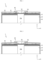
- FIG. 1 is a perspective view showing the structure of an upper portion of a battery cell according to an embodiment of the present disclosure
- FIG. 2 is a diagram for illustrating a rupture of a coupling portion between components as an internal pressure of the battery cell shown in FIG. 1 increases
- FIG. 3 is a diagram for illustrating a phenomenon in which a coupling portion of a terminal and a current collector moves together without being ruptured as the terminal rises when a CID of the present disclosure is omitted in the battery cell shown in FIGS. 1 and 2
- FIG. 4 is a diagram for illustrating a phenomenon in which a coupling portion of the terminal and the CID ruptures as the terminal rises when the CID of the present disclosure is applied to the battery cell shown in FIGS. 1 and 2 .
- the battery cell 1 may include an electrode assembly 10, a housing 20, a current collector (first current collector) 30, a terminal 40, and a CID (Current Interruption Device) 50.
- an electrode assembly 10 a housing 20, a current collector (first current collector) 30, a terminal 40, and a CID (Current Interruption Device) 50.
- the electrode assembly 10 may include a first electrode, a second electrode, and a separator interposed between the first electrode and the second electrode.
- the electrode assembly 10 may be, for example, a jelly roll-type electrode assembly in which a stack including a first electrode, a second electrode, and a separator is wound in one direction.
- the electrode assembly 10 may have a first uncoated portion 11 at the top end.
- the first uncoated portion 11 refers to a region of the first electrode that is not coated with electrode active material.
- the first uncoated portion 11 may be formed at one end of the first electrode and may extend along the winding direction of the electrode assembly 10.
- the first uncoated portion 11 may extend upward along the height direction of the electrode assembly 10 (a direction parallel to the Z-axis).
- the housing 20 may be configured to accommodate the electrode assembly 10 through an open portion provided at one side.
- the housing 20 may have a closed portion formed at a side opposite to the open portion.
- the current collector 30 may be disposed between the electrode assembly 10 and the closed portion of the housing 20.
- the current collector 30 may be electrically coupled to the electrode assembly 10.
- one side of the current collector 30 may be coupled with the first uncoated portion 11 provided at the top end of the electrode assembly 10.
- the current collector 30 and the electrode assembly 10 may be coupled to each other, for example, by laser welding, ultrasonic welding, etc.
- the first uncoated portion 11 may have segments formed by segmenting along the winding direction of the electrode assembly 10, and these segments may be bent toward the core of the electrode assembly 10, for example.
- the bent segments of the first uncoated portion 11 may overlap each other to form a plurality of layers.
- the current collector 30 may be coupled to the approximately flat surface formed by bending the first uncoated portion 11.
- the terminal 40 may be electrically coupled to the electrode assembly 10 through the closed portion of the housing 20.
- the terminal 40 may, for example, penetrate approximately the center of the closed portion of the housing 20.
- the terminal 40 may be fixed, for example, by riveting on the inner surface of the closed portion of the housing 20.
- the CID 50 may be interposed between the terminal 40 and the current collector 30.
- the CID 50 may be a plate containing a conductive metal.
- the first side of the CID 50 may be coupled with the terminal 40, and the second side, which is a side opposite to the first side, may be coupled with the current collector 30.
- the CID 50 may be coupled with the current collector 30.
- the CID may be coupled to the current collector with a coupling force greater than the coupling force with the terminal. In other words, the coupling force between the first side of the CID 50 and the terminal 40 may be stronger than the coupling force between the second side of the CID 50 and the current collector 30.
- the coupling portion between the terminal 40 and the CID 50 may be quickly ruptured when the housing 20 expands due to an increase in the internal pressure of the battery cell 1, which may block the flow of current through the terminal 40.
- the coupling portion between the current collector 30 and the electrode assembly 10 may be partially ruptured first and/or the rupture of the coupling portion between the current collector 30 and the terminal 40 may be delayed as the current collector 30 bends.
- the difference in coupling force as described above may be caused, for example, by the difference in coupling surface area.
- the area of the coupling surface between the CID 50 and the current collector 30 may be larger than the area of the coupling surface between the CID 50 and the terminal 40.
- the combined body including the electrode assembly 10, the current collector 30, and the CID 50 may be pushed through the open portion of the housing 20 so that the CID 50 comes into contact with the bottom of the terminal 40.
- the current collector 30, the CID 50, and the terminal 40 may be welded by inserting a welding device or irradiating a laser through the winding center hole 10a formed at approximately the center of the electrode assembly 10.
- the welding area between the CID 50 and the terminal 40 is smaller than the welding area between the current collector 30 and the CID 50, the welding region between the terminal 40 and the CID 50 may rupture quickly due to an increase in internal pressure.
- the coupling surface formed at the lower end of the terminal 40 may be provided at a position corresponding to the winding center hole 10a of the electrode assembly 10.
- the current collector 30 cannot be coupled to the electrode assembly 10 at the position corresponding to the coupling portion of the CID 50 and the terminal 40. Therefore, when the closed portion is bent due to an increase in the internal pressure of the battery cell 1 and the terminal 40 rises accordingly, the current collector 30 may be bent in a region corresponding to the winding center hole 10a. This bending of the current collector 30 may be a cause of disturbing the rupture of the coupling portion between the terminal 40 and the CID 50. If the CID 50 of the present disclosure is applied, the CID 50 may reinforce the rigidity of the current collector 30, and thus the rupture of the coupling portion between the terminal 40 and the CID 50 may occur more quickly.
- the CID 50 may be coupled with the current collector 30 at the inner side (B region) and the outer side (A region) of the region corresponding to the winding center hole 10a.
- the bending of the current collector 30 and the CID 50 may be further suppressed, and thus the coupling portion of the terminal 40 and the CID 50 may rupture more quickly.
- the battery cell 1 of the present disclosure may include an insulator IS and/or an insulating gasket G1.
- the insulator IS may be disposed in the space formed between the closed portion of the housing 20 and the current collector 30.
- the insulator IS may include an insulating material.
- the insulator IS may prevent contact between the current collector 30 and the housing 20, which are configured to have different polarities.
- the insulating gasket G1 may be inserted between the terminal 40 and the housing 20.
- the insulating gasket G1 may contain an insulating material.
- the insulating gasket G1 may prevent contact between the terminal 40 and the housing 20, which are configured to have different polarities.
- FIG. 5 is a diagram showing a battery cell to which a current collector of a different type from the current collector shown in FIG. 1 is applied
- FIG. 6 is a diagram for illustrating the rupture of the coupling portion between components as the internal pressure of the battery cell shown in FIG. 5 increases.
- FIGS. 7 and 8 are diagrams showing an exemplary form of the current collector applied to the battery cell shown in FIGS. 5 and 6 .
- FIG. 9 is a diagram for illustrating a phenomenon in which, when the CID of the present disclosure is omitted in the battery cell shown in FIGS.
- FIG. 10 is diagram for illustrating a phenomenon in which, when the CID of the present disclosure is coupled only to a second coupling portion of the current collector in the battery cell shown in FIGS. 5 and 6 , the coupling portion of the terminal and the CID moves together without being ruptured as the terminal rises.
- FIG. 11 is diagram for illustrating a phenomenon in which, when the CID of the present disclosure is coupled with both the first coupling portion and the second coupling portion of the current collector in the battery cell shown in FIGS. 5 and 6 , the coupling portion of the terminal and the CID ruptures as the terminal rises.
- the current collector 30 may include a first coupling portion 31 and a second coupling portion 32.
- the first coupling portion 31 may be electrically coupled to the electrode assembly 10.
- the first coupling portion 31 may be coupled, for example, with the first uncoated portion 11 of the electrode assembly 10.
- the second coupling portion 32 may be located to be spaced apart from the first coupling portion 31 along the radial direction of the electrode assembly 10.
- the second coupling portion 32 may be coupled to the terminal 40 with the CID 50 being interposed therebetween.
- the first coupling portion 31 provided for coupling with the electrode assembly 10 and the second coupling portion 32 provided for coupling with the terminal 40 are not directly connected to each other but indirectly connected. Therefore, when an impact is applied to one of the welding portion formed in the first coupling portion 31 and the welding portion formed in the second coupling portion 32, the shock may be prevented from being directly transmitted to the other one. This may reduce the risk of damage to the welding portion due to external shock.
- the second coupling portion 32 may be provided at a position corresponding to the winding center hole 10a of the electrode assembly 10.
- the second coupling portion 32 is shown to have a larger size to cover the winding center hole 10a, but the present disclosure is not limited thereto.
- the second coupling portion 32 may have a size substantially identical to or smaller than the winding center hole 10a.
- the current collector 30 may include a connection portion 33 configured to electrically connect the first coupling portion 31 and the second coupling portion 32.
- the connection portion 33 may include a border portion 33a having an approximately rim shape with an empty center, and a bridge portion 33b for connecting the border portion 33a and the second coupling portion 32.
- the bridge portion 33b may be provided in one or in plurality.
- the first coupling portion 31 may extend inward from the border portion 33a.
- the first coupling portion 31 may be provided in plurality.
- the second coupling portion 32 may be arranged to be surrounded by the plurality of first coupling portions 31.
- the CID 50 may be coupled with both the first coupling portion 31 and the second coupling portion 32.
- the welding portion between the terminal 40 and the CID 50 may rupture quickly as shown in FIG. 6 , thereby quickly blocking the electrical flow through the terminal 40.
- the CID 50 may be configured to cover both the first coupling portion 31 and the second coupling portion 32 along the radial direction of the electrode assembly 10.
- FIG. 12 is a diagram showing a battery cell to which a CID gasket is additionally applied in the battery cell shown in FIG. 5
- FIG. 13 is a diagram for illustrating the rupture of the coupling portion between components as the internal pressure of the battery cell shown in FIG. 12 increases.
- FIGS. 14 and 15 are diagrams showing a battery cell having a structure in which the CID gasket is disposed at a different position compared to the battery cell shown in FIG. 12 .
- the battery cell 1 of the present disclosure may include a CID gasket 60.
- the CID gasket 60 may include a material with insulating properties.
- the CID gasket 60 may be interposed between the closed portion of the housing 20 and the current collector 30.
- the CID gasket 60 may maintain the separated state when the terminal 40 and the CID 50 are separated from each other due to an increase in pressure inside the housing 20.
- the CID gasket 60 may be configured to have an elastic restoring force in the expansion direction between the closed portion of the housing 20 and the current collector 30.
- the CID gasket 60 may be interposed between the closed portion and the current collector 30 in a compressed state to have a thickness corresponding to the distance between the closed portion and the current collector 30.
- the closed portion of the housing 20 which swells upward due to an increase in internal pressure, may not be restored to its original shape but remain in a deformed state.
- the terminal 40 may rise together, and the coupling portion between the terminal 40 and the CID 50 may rupture accordingly.
- the CID gasket 60 When the CID gasket 60 is applied, the terminal 40 and the CID 50 may be maintained to be spaced apart from each other, and the flow of current through the terminal 40 may be maintained to be blocked.
- the CID gasket 60 may be configured to expand as the temperature inside the housing 20 increases.
- the CID gasket 60 may contain a material that expands due to heat.
- the CID gasket 60 may contain a foaming resin.
- the CID gasket 60 may be configured to expand, for example, at a temperature at which the closed portion of the housing 20 swells upward.
- the CID gasket 60 may be arranged to be at least partially interposed between the CID 50 and the closed portion of the housing 20.
- the coupling portion between the current collector 30 and the electrode assembly 10 may be pressurized by the CID gasket 60. Therefore, when the terminal 40 rises, it is possible to prevent the coupling portion between the current collector 30 and the electrode assembly 10 from being damaged first before the coupling portion between the terminal 40 and the CID 50 is damaged.
- the entire region of the CID gasket 60 may be located on the CID 50, as shown in FIG. 15 .
- the location where the CID gasket 60 of the present disclosure is disposed is not limited thereto, and the entire region of the CID gasket 60 may be located outside of the CID 50 as shown in FIG. 14 .
- FIG. 16 is a drawing showing the appearance of the battery cell according to the present disclosure
- FIG. 17 is a diagram showing the overall internal structure of the battery cell shown in FIG. 16
- FIG. 18 is a partial cross-sectional view showing the structure of a lower portion of the battery cell according to the present disclosure.
- the battery cell 1 of the present disclosure may include a battery cap 70 configured to cover the open portion of the housing 20.
- the battery cap 70 may have a venting portion 71 configured to be weak compared to the surrounding region.
- the venting portion 71 may be configured to have a smaller thickness than the surrounding region by notching one side or both sides of the battery cap 70.
- the coupling portion between the terminal 40 and the CID 50 of the present disclosure as described above may be configured to rupture at low pressure than the venting pressure of the venting portion 71, namely the pressure at which the venting portion 71 ruptures. This is to ensure safety in battery use by blocking the flow of current through the terminal 40 before a thermal event caused by venting spreads.
- the battery cell 1 of the present disclosure may include a sealing gasket G2 interposed between the battery cap 70 and the inner surface of the housing 20.
- the sealing gasket G2 may be configured to enhance the sealing properties of the housing 20.
- the battery cell 1 of the present disclosure may be configured such that the closed portion of the terminal 40 and the housing 20 function as a first electrode terminal and a second electrode terminal, respectively.
- the terminal 40 may be electrically connected to the first uncoated portion 11 of the electrode assembly 10 through the current collector (first current collector) 30, and thus may have first polarity.
- the housing 20 may be electrically connected to the second uncoated portion 12 of the electrode assembly 10, and thus may have second polarity.
- the housing 20 and the second uncoated portion 12 of the electrode assembly 10 may be electrically connected, for example, through a second current collector P.
- the second uncoated portion 12 refers to a region in the second electrode that is not coated with electrode active material.
- the second uncoated portion 12 may be formed at one end of the second electrode and may extend along the winding direction of the electrode assembly 10.
- the second uncoated portion 12 may extend downward along the height direction of the electrode assembly 10 (a direction parallel to the Z-axis).
- the second current collector P may be coupled onto the second uncoated portion 12.
- the second uncoated portion 12 may have segments similar to the first uncoated portion 11 described above, and the segments may be bent toward the core of the electrode assembly 10.
- the bent segments of the second uncoated portion 12 may overlap each other to form a plurality of layers.
- the second current collector P may be coupled to the approximately flat surface formed by bending the second uncoated portion 12.
- the second current collector P may be coupled onto the inner side of the housing 20.
- the housing 20 may include a beading portion 21 press-fitted along the outer circumference.
- the housing 20 may include a crimping portion 22 that is formed to extend and bend from the beading portion 21 to surround the peripheral edge of the battery cap 70.
- the second current collector P may be interposed between one side of the beading portion 21 and the sealing gasket G2.
- FIG. 19 is a diagram showing a battery pack according to an embodiment of the present disclosure.
- the battery pack 3 may include the battery cell 1 according to an embodiment of the present disclosure and a pack housing 2 configured to accommodate the battery cell 1.
- the battery cell 1 may be provided in plurality, and the plurality of battery cells 1 may be electrically connected to each other.
- the battery cell 1 of the present disclosure may be configured so that the terminal 40 and the closed portion of the housing 20 may function as a first electrode terminal and a second electrode terminal, respectively (see FIGS. 17 and 18 ). Therefore, when arranging a plurality of battery cells 1 in the pack housing 2, all battery cells 1 may be arranged so that the terminals 40 face upward, and thus electrical connection may be made at the top of the battery cells 1.
- FIG. 20 is a drawing showing a vehicle according to an embodiment of the present disclosure.
- the vehicle 5 may include the battery pack 3 according to an embodiment of the present disclosure.
- the vehicle 5 may be configured to operate by receiving power from the battery pack 3.
- the vehicle 5 may be, for example, an electric vehicle or a hybrid electric vehicle.
Landscapes
- Chemical & Material Sciences (AREA)
- Chemical Kinetics & Catalysis (AREA)
- Electrochemistry (AREA)
- General Chemical & Material Sciences (AREA)
- Engineering & Computer Science (AREA)
- Aviation & Aerospace Engineering (AREA)
- Manufacturing & Machinery (AREA)
- Connection Of Batteries Or Terminals (AREA)
Applications Claiming Priority (2)
| Application Number | Priority Date | Filing Date | Title |
|---|---|---|---|
| KR1020230077099A KR20240176383A (ko) | 2023-06-15 | 2023-06-15 | 배터리 셀, 그리고 이를 포함하는 배터리 팩 및 자동차 |
| PCT/KR2024/007984 WO2024258153A1 (fr) | 2023-06-15 | 2024-06-11 | Cellule de batterie, et bloc-batterie et véhicule la comprenant |
Publications (2)
| Publication Number | Publication Date |
|---|---|
| EP4576407A1 true EP4576407A1 (fr) | 2025-06-25 |
| EP4576407A4 EP4576407A4 (fr) | 2026-01-21 |
Family
ID=93852405
Family Applications (1)
| Application Number | Title | Priority Date | Filing Date |
|---|---|---|---|
| EP24823671.3A Pending EP4576407A4 (fr) | 2023-06-15 | 2024-06-11 | Cellule de batterie, et bloc-batterie et véhicule la comprenant |
Country Status (5)
| Country | Link |
|---|---|
| EP (1) | EP4576407A4 (fr) |
| KR (1) | KR20240176383A (fr) |
| CN (1) | CN119948692A (fr) |
| MX (1) | MX2025006862A (fr) |
| WO (1) | WO2024258153A1 (fr) |
Family Cites Families (8)
| Publication number | Priority date | Publication date | Assignee | Title |
|---|---|---|---|---|
| KR100578804B1 (ko) * | 2004-03-29 | 2006-05-11 | 삼성에스디아이 주식회사 | 캡 조립체 및 이를 구비한 이차 전지 |
| JP2018037327A (ja) * | 2016-09-01 | 2018-03-08 | トヨタ自動車株式会社 | 密閉型二次電池 |
| JP6792802B2 (ja) * | 2017-09-07 | 2020-12-02 | トヨタ自動車株式会社 | 密閉型電池および密閉型電池の製造方法 |
| KR102264635B1 (ko) * | 2017-11-23 | 2021-06-15 | 주식회사 엘지에너지솔루션 | 파우치 형 이차 전지 |
| US11923566B2 (en) * | 2018-02-27 | 2024-03-05 | Panasonic Holdings Corporation | Sealed battery |
| KR102461773B1 (ko) * | 2018-03-16 | 2022-11-02 | 주식회사 엘지에너지솔루션 | 이차전지 및 그 이차전지의 제조방법 |
| KR20230053484A (ko) * | 2021-10-14 | 2023-04-21 | 주식회사 엘지에너지솔루션 | 레이저 용접이 적용된 원통형 이차전지와 그 제조방법, 이러한 이차전지를 포함하는 배터리 팩 및 자동차 |
| KR20230077099A (ko) | 2021-11-25 | 2023-06-01 | 이병우 | 발광되는 콘센트 스윗치용 커버 |
-
2023
- 2023-06-15 KR KR1020230077099A patent/KR20240176383A/ko active Pending
-
2024
- 2024-06-11 WO PCT/KR2024/007984 patent/WO2024258153A1/fr not_active Ceased
- 2024-06-11 EP EP24823671.3A patent/EP4576407A4/fr active Pending
- 2024-06-11 CN CN202480004110.7A patent/CN119948692A/zh active Pending
-
2025
- 2025-06-12 MX MX2025006862A patent/MX2025006862A/es unknown
Also Published As
| Publication number | Publication date |
|---|---|
| CN119948692A (zh) | 2025-05-06 |
| EP4576407A4 (fr) | 2026-01-21 |
| KR20240176383A (ko) | 2024-12-24 |
| WO2024258153A1 (fr) | 2024-12-19 |
| MX2025006862A (es) | 2025-07-01 |
Similar Documents
| Publication | Publication Date | Title |
|---|---|---|
| EP3451410B1 (fr) | Ensemble capuchon pour une seconde batterie et seconde batterie | |
| CN102005597B (zh) | 可再充电电池 | |
| KR100578804B1 (ko) | 캡 조립체 및 이를 구비한 이차 전지 | |
| KR100551887B1 (ko) | 이차전지 | |
| EP2362461B1 (fr) | Batterie rechargeable | |
| EP2325924B1 (fr) | Batterie secondaire comprenant un élément provoquant un court-circuit | |
| US20100316894A1 (en) | Integrated battery pressure relief and terminal isolation system | |
| EP2924763B1 (fr) | Batterie secondaire | |
| CN106058139A (zh) | 电流切断装置以及使用电流切断装置的蓄电装置 | |
| US8679673B2 (en) | Cap assembly, can, and secondary battery employing the same | |
| CN107871840B (zh) | 电池单元 | |
| KR100399783B1 (ko) | 이차 전지와 그 제조방법 | |
| EP3062368B1 (fr) | Batterie rechargeable | |
| KR100846955B1 (ko) | 원통형 이차전지 | |
| US7939191B2 (en) | Rechargeable battery and coupling structure thereof | |
| CN1960027B (zh) | 密封方形锂离子电池 | |
| KR20150028632A (ko) | 단락부재는 갖는 이차 전지 | |
| CN107808982B (zh) | 二次电池 | |
| KR101303396B1 (ko) | 몰딩부를 구비한 이차 전지 | |
| EP4576407A1 (fr) | Cellule de batterie, et bloc-batterie et véhicule la comprenant | |
| KR20180102305A (ko) | 바이메탈로 이루어진 전류 차단 부재를 포함하는 캡 어셈블리 | |
| KR101305461B1 (ko) | 이차 전지 | |
| EP4657647A1 (fr) | Batterie, bloc-batterie la comprenant, et véhicule comprenant un bloc-batterie | |
| EP4712254A1 (fr) | Batterie, bloc-batterie comprenant une batterie, et véhicule comprenant un bloc-batterie | |
| KR20220061660A (ko) | 이차 전지 및 이를 포함하는 디바이스 |
Legal Events
| Date | Code | Title | Description |
|---|---|---|---|
| STAA | Information on the status of an ep patent application or granted ep patent |
Free format text: STATUS: THE INTERNATIONAL PUBLICATION HAS BEEN MADE |
|
| PUAI | Public reference made under article 153(3) epc to a published international application that has entered the european phase |
Free format text: ORIGINAL CODE: 0009012 |
|
| STAA | Information on the status of an ep patent application or granted ep patent |
Free format text: STATUS: REQUEST FOR EXAMINATION WAS MADE |
|
| 17P | Request for examination filed |
Effective date: 20250318 |
|
| AK | Designated contracting states |
Kind code of ref document: A1 Designated state(s): AL AT BE BG CH CY CZ DE DK EE ES FI FR GB GR HR HU IE IS IT LI LT LU LV MC ME MK MT NL NO PL PT RO RS SE SI SK SM TR |
|
| A4 | Supplementary search report drawn up and despatched |
Effective date: 20251222 |
|
| RIC1 | Information provided on ipc code assigned before grant |
Ipc: H01M 50/583 20210101AFI20251216BHEP Ipc: H01M 50/538 20210101ALI20251216BHEP Ipc: H01M 50/152 20210101ALI20251216BHEP Ipc: H01M 50/342 20210101ALI20251216BHEP Ipc: H01M 50/213 20210101ALI20251216BHEP Ipc: H01M 50/249 20210101ALI20251216BHEP Ipc: H01M 50/559 20210101ALI20251216BHEP Ipc: H01M 50/107 20210101ALI20251216BHEP Ipc: H01M 50/188 20210101ALI20251216BHEP Ipc: H01M 50/536 20210101ALI20251216BHEP Ipc: H01M 50/567 20210101ALI20251216BHEP Ipc: H01M 50/581 20210101ALI20251216BHEP Ipc: H01M 50/147 20210101ALI20251216BHEP Ipc: H01M 50/184 20210101ALI20251216BHEP Ipc: H01M 50/578 20210101ALI20251216BHEP |