EP4579711A2 - Elektrisches gerät, elektrisches unterbrechungssystem mit einem solchen gerät - Google Patents
Elektrisches gerät, elektrisches unterbrechungssystem mit einem solchen gerät Download PDFInfo
- Publication number
- EP4579711A2 EP4579711A2 EP25176668.9A EP25176668A EP4579711A2 EP 4579711 A2 EP4579711 A2 EP 4579711A2 EP 25176668 A EP25176668 A EP 25176668A EP 4579711 A2 EP4579711 A2 EP 4579711A2
- Authority
- EP
- European Patent Office
- Prior art keywords
- electrode
- electrical
- circuit breaker
- fuse
- current
- Prior art date
- Legal status (The legal status is an assumption and is not a legal conclusion. Google has not performed a legal analysis and makes no representation as to the accuracy of the status listed.)
- Pending
Links
Images


Classifications
-
- H—ELECTRICITY
- H01—ELECTRIC ELEMENTS
- H01H—ELECTRIC SWITCHES; RELAYS; SELECTORS; EMERGENCY PROTECTIVE DEVICES
- H01H9/00—Details of switching devices, not covered by groups H01H1/00 - H01H7/00
- H01H9/10—Adaptation for built-in fuses
- H01H9/106—Adaptation for built-in fuses fuse and switch being connected in parallel
-
- H—ELECTRICITY
- H01—ELECTRIC ELEMENTS
- H01H—ELECTRIC SWITCHES; RELAYS; SELECTORS; EMERGENCY PROTECTIVE DEVICES
- H01H85/00—Protective devices in which the current flows through a part of fusible material and this current is interrupted by displacement of the fusible material when this current becomes excessive
- H01H85/02—Details
- H01H85/0241—Structural association of a fuse and another component or apparatus
-
- H—ELECTRICITY
- H01—ELECTRIC ELEMENTS
- H01H—ELECTRIC SWITCHES; RELAYS; SELECTORS; EMERGENCY PROTECTIVE DEVICES
- H01H39/00—Switching devices actuated by an explosion produced within the device and initiated by an electric current
- H01H39/006—Opening by severing a conductor
-
- H—ELECTRICITY
- H01—ELECTRIC ELEMENTS
- H01H—ELECTRIC SWITCHES; RELAYS; SELECTORS; EMERGENCY PROTECTIVE DEVICES
- H01H37/00—Thermally-actuated switches
- H01H37/02—Details
- H01H37/32—Thermally-sensitive members
- H01H37/52—Thermally-sensitive members actuated due to deflection of bimetallic element
- H01H37/54—Thermally-sensitive members actuated due to deflection of bimetallic element wherein the bimetallic element is inherently snap acting
- H01H2037/5463—Thermally-sensitive members actuated due to deflection of bimetallic element wherein the bimetallic element is inherently snap acting the bimetallic snap element forming part of switched circuit
-
- H—ELECTRICITY
- H01—ELECTRIC ELEMENTS
- H01H—ELECTRIC SWITCHES; RELAYS; SELECTORS; EMERGENCY PROTECTIVE DEVICES
- H01H37/00—Thermally-actuated switches
- H01H37/74—Switches in which only the opening movement or only the closing movement of a contact is effected by heating or cooling
- H01H37/76—Contact member actuated by melting of fusible material, actuated due to burning of combustible material or due to explosion of explosive material
- H01H37/761—Contact member actuated by melting of fusible material, actuated due to burning of combustible material or due to explosion of explosive material with a fusible element forming part of the switched circuit
-
- H—ELECTRICITY
- H01—ELECTRIC ELEMENTS
- H01H—ELECTRIC SWITCHES; RELAYS; SELECTORS; EMERGENCY PROTECTIVE DEVICES
- H01H39/00—Switching devices actuated by an explosion produced within the device and initiated by an electric current
- H01H39/002—Switching devices actuated by an explosion produced within the device and initiated by an electric current provided with a cartridge-magazine
Definitions
- the invention relates to an electrical apparatus and an electrical system for interrupting an electric current.
- the invention is particularly applicable to the field of electrical protection.
- Fuses typically consist of a fuse blade placed in a housing filled with a material such as silica.
- the blade is configured to melt when the current flowing through the fuse exceeds a predetermined value for a certain period of time.
- WO 2018/167169 A1 describes an example of such an electrical device, in which a fuse is connected in parallel with a pyrotechnic circuit breaker.
- the pyrotechnic circuit breaker is configured to trigger with a very short reaction time in the event of an electrical fault, and the fuse is configured to ensure total interruption of the current, for example to prevent any re-formation of an electric arc in the pyrotechnic circuit breaker.
- the invention relates to an electrical apparatus as defined in claim 1.
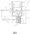
- FIG. 1 represents an embodiment of an electrical system 2 configured to interrupt an electric current, for example in order to protect an electrical load or an electrical installation.
- the device 2 comprises a circuit breaker 4 having terminals 6 and 8, allowing the circuit breaker 4 to be connected to an electrical circuit, for example between an electrical load and a generator.
- the apparatus 2 also comprises an electrical apparatus 10 and a fuse 12 electrically connected in parallel with the circuit breaker 4 between terminals 6 and 8.
- the circuit breaker 4 can be switched from an electrically conductive state to an electrically blocking (or open) state.
- the circuit breaker 4 may be a pyrotechnic circuit breaker.
- the circuit breaker 4 may include an explosive charge configured to, when triggered, physically sever an electrical conductor extending between the terminals 8 and 6 of the circuit breaker 4.
- the circuit breaker 4 comprises a body 20 and a cut-off member 22 (such as a piston) configured to move by translation in the body 20, for example following the triggering of a pyrotechnic charge (not illustrated).
- a cut-off member 22 such as a piston
- the cutting member 22 is configured to cut an internal electrical conductor housed inside the body 20, this electrical conductor connecting the terminal 6 to the terminal 8.
- the electrical device 10 comprises a body 30 delimiting a closed interior volume, a first electrode E1, a second electrode E2 and a third electrode E3.
- the fusible element F1 melts. This leads to the appearance of an electric arc A between the first electrode E1 and the second electrode E2. The arc A is then deflected to establish itself between the first electrode E1 and the third electrode E3.
- the free ends 40, 42 of the first electrode and the second electrode are partially separated by an electrically insulating barrier 44.
- Insert (b) represents a second alternative embodiment 10b of the apparatus 10 of the Figure 1 .
- the apparatus is arranged such that the breakdown voltage between the first electrode and the second electrode E2 is lower than the breakdown voltage between the first electrode E1 and the third electrode E3.
- the body 50 of the device 10b has a tubular or cylindrical shape.
- the first electrode E1 and the third electrode E3 are aligned with each other and with the tubular body and open onto opposite faces of the tubular body.
- the second electrode E2 opens into the body 50 through the wall cylindrical body, off-center (or asymmetrical) with respect to the first electrode E1 and the third electrode E3.
- the second electrode E2 is off-center (or asymmetrical) with respect to the first electrode E1 and the third electrode E3.
- the distance between the electrodes E1 and E3 is greater than 1.2 times the distance between the electrodes E1 and E2.
- the end faces 52, 54 of the body 50 may have a conical or trapezoidal shape.
- the internal wall of said faces may comprise electrically conductive pads.
- the fusible conductive element F1 can be replaced by a bimetallic strip, or more generally by an electrical conductor made of shape memory material, connecting the first electrode E1 to the second electrode E2.
- the apparatus 10 comprises an electrically conductive element connecting the first electrode E1 to the second electrode E2, the electrically conductive element being configured to be modified when the current passing through it exceeds said threshold value.
- the electrically conductive element is the fusible element F1
- said modification consists of a melting of the fusible element F1.
- the electrically conductive element is a deformable shape memory material, such as a bimetallic strip
- the modification consists of a deformation.
- the apparatus 10 as well as its variants, can be used independently of the electrical system 2.
- FIG. 3 represents a first state of the system 2 immediately after the circuit breaker 4 has been triggered.
- the internal conductor has been cut into portions 24, 26 and 28 by the cut-off member 22.
- the electric current C1 coming from the terminal 8 continues to flow through the circuit breaker, because electric arcs, denoted A, have formed on the one hand between the conductor portions 24 and 26 and on the other hand between the conductor portions 26 and 28.
- FIG. 4 represents a second state of system 2 subsequent to the first state.
- the electric current C1 continues to flow through the circuit breaker 4 due to the presence of the electric arcs A1 and A2.
- the fusible conductive element F1 does not melt. This means that the voltage generated by the electric arcs A1 and A2 then A2 and A3 was sufficient in itself to oppose the flow of current and to cancel it. In this case, the current C1 is canceled while the fuse F1 is simply heated by the Joule effect, but is not melted.
- the final electrical insulation is ensured in the circuit breaker by the distances between the free ends of the conductors, and in the device 10 by the distance in the air between the electrodes E1 and E3 (or the wall 62 if present).
- FIG. 5 represents a third state of system 2, subsequent to the second state.
- the electric arc A established between the first electrode E1 and the second electrode E2 is deflected to establish itself between the first electrode E1 and the third electrode E3 (electric arc A on the Figure 5 ).
- fuse 12 blows to interrupt the flow of electric current C1. The flow of current in electrical system 2 is then interrupted.
- the final electrical insulation is ensured in the circuit breaker by the distances between the free ends of the conductors, and by the fuse F2.
- the fuse 12 Since the fuse 12 is not permanently crossed by the electric current flowing between the terminals 6 and 8 of the circuit breaker 4 under normal circumstances (the fuse 12 is protected from this current by the device 10), then the service life of the fuse 12 can be extended. This increases the reliability of the electrical system 2.
- the characteristics of the fuse 12 are chosen as a function of the cooling time of the ionized gases in the housing 30.
- the electrical system 2b is generally identical to the system 2 and has a similar operation, except that the second electrode E2 is now connected to the central conductor portion 28, instead of opening freely into the extinguishing chamber.
- the insert (a) represents a first embodiment of a cartridge 70 in which the device 10 and the fuse 12 are integrated.
- region 76 comprises the absorbing elements 32, 34 as well as, where appropriate, the voltage suppressor element 60.
- the fusible conductive element F1 connects the first electrode E1 to the voltage suppressor element 60 or directly to the second electrode E2.
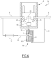
- Insert (b) of the Figure 7 represents a second embodiment of a cartridge 80 in which at least some of the components of the device 10 are integrated. This embodiment is especially applicable to the embodiment of the electrical system 2b illustrated in the figure 8 .
- This embodiment differs in particular from the other embodiments of the system 2a in that the device 10 is produced in the form of an assembly 90 in which the fuse element F1 is associated with a second circuit breaker 92 comprising a pyrotechnic charge 94, a movable contact 96 and connection terminals 98.
- One of the terminals 98 is connected to the fuse 12 while the other terminal 98 is connected to a first electrode 100A connected to the terminal 8.
- a second electrode 100B connects the fuse element F1 to the central portion 28 via the voltage suppressor element 60 and a third electrode 100C.
- the electrode 100C is connected directly to the electrode 100B.
- the pyrotechnic charge 94 is connected to the electrode 100B and the electrode 100A, so as to be triggered when the fuse element F1 has melted.
- the system allows the current arriving from the terminal 8 of the circuit breaker 4 to be diverted to the fuse 12.
- the cartridge 80 comprises a tubular or cylindrical body 82 which delimits a region 84 comprising a fuse blade F1 immersed in a siliceous material, such as sand, and extending between the electrodes 100A and 100B.
- the tubular body 82 is made of electrically insulating material, for example plastic, or ceramic, or a composite material comprising glass fibers embedded in a resin matrix, or any suitable material.
- the apparatus 10 can be integrated inside the circuit breaker 4.
- the electrodes E1 and E2 are arranged in the cut-off member 22, emerging from the cut-off member 22, the latter being electrically conductive, while the electrode E3 is arranged in the body 20 of the circuit breaker 4, so as to be opposite and aligned with the electrode E1 when the cut-off member 22 is in the deployed position.
- the fuse 12 is only connected in parallel with the circuit breaker 4 when the circuit breaker 4 is triggered and only on condition that the energy passing through the circuit breaker has exceeded a threshold value, this to prevent the fuse 12 from being permanently crossed by an electric current, since this could lead to premature aging of the fuse.
- the invention also makes it possible to guarantee rapid opening of the circuit even when the current passing through it when it is triggered is low or zero.
- the threshold value determined by the fuse element rating F1 has many advantages in practical terms and in terms of ease of industrial production.
- the threshold value is easy to adjust during product development and can be easily controlled during large-scale production.
- This threshold value is also stable over time, being relatively insensitive to aging (unlike a plastic membrane, for example) and insensitive to ambient pressure.
- the threshold value tends to be relatively independent of the inductance value of the installation.
Landscapes
- Engineering & Computer Science (AREA)
- Power Engineering (AREA)
- Fuses (AREA)
- Electric Propulsion And Braking For Vehicles (AREA)
- Electrical Discharge Machining, Electrochemical Machining, And Combined Machining (AREA)
- Perforating, Stamping-Out Or Severing By Means Other Than Cutting (AREA)
- Protection Of Static Devices (AREA)
Applications Claiming Priority (3)
| Application Number | Priority Date | Filing Date | Title |
|---|---|---|---|
| FR2101841A FR3120155A1 (fr) | 2021-02-25 | 2021-02-25 | Appareil électrique, système électrique de coupure comportant un tel appareil |
| PCT/EP2022/054708 WO2022180182A1 (fr) | 2021-02-25 | 2022-02-24 | Appareil électrique, système électrique de coupure comportant un tel appareil |
| EP22713867.4A EP4298653B1 (de) | 2021-02-25 | 2022-02-24 | Elektrische vorrichtung und abschaltsystem mit einer solchen vorrichtung |
Related Parent Applications (1)
| Application Number | Title | Priority Date | Filing Date |
|---|---|---|---|
| EP22713867.4A Division EP4298653B1 (de) | 2021-02-25 | 2022-02-24 | Elektrische vorrichtung und abschaltsystem mit einer solchen vorrichtung |
Publications (2)
| Publication Number | Publication Date |
|---|---|
| EP4579711A2 true EP4579711A2 (de) | 2025-07-02 |
| EP4579711A3 EP4579711A3 (de) | 2025-09-17 |
Family
ID=76375144
Family Applications (2)
| Application Number | Title | Priority Date | Filing Date |
|---|---|---|---|
| EP22713867.4A Active EP4298653B1 (de) | 2021-02-25 | 2022-02-24 | Elektrische vorrichtung und abschaltsystem mit einer solchen vorrichtung |
| EP25176668.9A Pending EP4579711A3 (de) | 2021-02-25 | 2022-02-24 | Elektrisches gerät, elektrisches unterbrechungssystem mit einem solchen gerät |
Family Applications Before (1)
| Application Number | Title | Priority Date | Filing Date |
|---|---|---|---|
| EP22713867.4A Active EP4298653B1 (de) | 2021-02-25 | 2022-02-24 | Elektrische vorrichtung und abschaltsystem mit einer solchen vorrichtung |
Country Status (5)
| Country | Link |
|---|---|
| US (1) | US12525417B2 (de) |
| EP (2) | EP4298653B1 (de) |
| CN (1) | CN116918020A (de) |
| FR (1) | FR3120155A1 (de) |
| WO (1) | WO2022180182A1 (de) |
Families Citing this family (1)
| Publication number | Priority date | Publication date | Assignee | Title |
|---|---|---|---|---|
| FR3120155A1 (fr) | 2021-02-25 | 2022-08-26 | Mersen France Sb Sas | Appareil électrique, système électrique de coupure comportant un tel appareil |
Citations (2)
| Publication number | Priority date | Publication date | Assignee | Title |
|---|---|---|---|---|
| WO2018167169A1 (fr) | 2017-03-17 | 2018-09-20 | Autoliv Development Ab | Interrupteur pyrotechnique avec moyens fusibles |
| WO2020260382A1 (fr) | 2019-06-25 | 2020-12-30 | Mersen France Sb Sas | Coupe-circuit électrique |
Family Cites Families (9)
| Publication number | Priority date | Publication date | Assignee | Title |
|---|---|---|---|---|
| FR1297273A (fr) * | 1961-05-16 | 1962-06-29 | Commutateur électrique commandé par un échauffement | |
| AT297831B (de) * | 1969-11-13 | 1972-04-10 | Electrovac | Elektrischer Schalter |
| US3805208A (en) * | 1973-06-14 | 1974-04-16 | Alister C Mc | Protector for electric circuits |
| CN202632917U (zh) * | 2010-12-31 | 2012-12-26 | 厦门赛尔特电子有限公司 | 一种温度保险丝与电阻结合的装置 |
| DE102012112480B4 (de) | 2012-07-04 | 2018-10-04 | Dehn + Söhne Gmbh + Co. Kg | Gekapselte, blitzstromtragfähige und folgestrombegrenzende Überspannungsschutzeinrichtung mit mindestens einer Funkenstrecke |
| CN104662635B (zh) * | 2012-09-28 | 2017-11-17 | 奥托立夫开发公司 | 电烟火开关 |
| DE102017125208B4 (de) | 2017-10-27 | 2021-08-12 | Auto-Kabel Management Gmbh | Elektrisches Sicherungselement sowie Verfahren zum Betreiben eines elektrischen Sicherungselementes |
| US10636607B2 (en) * | 2017-12-27 | 2020-04-28 | Eaton Intelligent Power Limited | High voltage compact fused disconnect switch device with bi-directional magnetic arc deflection assembly |
| FR3120155A1 (fr) | 2021-02-25 | 2022-08-26 | Mersen France Sb Sas | Appareil électrique, système électrique de coupure comportant un tel appareil |
-
2021
- 2021-02-25 FR FR2101841A patent/FR3120155A1/fr active Pending
-
2022
- 2022-02-24 EP EP22713867.4A patent/EP4298653B1/de active Active
- 2022-02-24 CN CN202280016051.6A patent/CN116918020A/zh active Pending
- 2022-02-24 US US18/547,608 patent/US12525417B2/en active Active
- 2022-02-24 WO PCT/EP2022/054708 patent/WO2022180182A1/fr not_active Ceased
- 2022-02-24 EP EP25176668.9A patent/EP4579711A3/de active Pending
Patent Citations (2)
| Publication number | Priority date | Publication date | Assignee | Title |
|---|---|---|---|---|
| WO2018167169A1 (fr) | 2017-03-17 | 2018-09-20 | Autoliv Development Ab | Interrupteur pyrotechnique avec moyens fusibles |
| WO2020260382A1 (fr) | 2019-06-25 | 2020-12-30 | Mersen France Sb Sas | Coupe-circuit électrique |
Also Published As
| Publication number | Publication date |
|---|---|
| WO2022180182A1 (fr) | 2022-09-01 |
| FR3120155A1 (fr) | 2022-08-26 |
| EP4298653A1 (de) | 2024-01-03 |
| US20240234067A9 (en) | 2024-07-11 |
| US20240136136A1 (en) | 2024-04-25 |
| EP4579711A3 (de) | 2025-09-17 |
| CN116918020A (zh) | 2023-10-20 |
| EP4298653B1 (de) | 2025-06-11 |
| US12525417B2 (en) | 2026-01-13 |
Similar Documents
| Publication | Publication Date | Title |
|---|---|---|
| EP3991191B1 (de) | Elektrischer schutzschalter | |
| FR3101478A1 (fr) | Mecanismes de declenchement par levitation de contacts a utiliser avec des dispositifs de commutation incorporant des elements pyrotechniques | |
| WO2018167169A1 (fr) | Interrupteur pyrotechnique avec moyens fusibles | |
| FR2928026A1 (fr) | Dispositif de protection contre les surtensions comprenant des moyens de deconnexion selectifs | |
| EP1743346B1 (de) | Überspannungsschutzeinrichtung mit lichtbogenlöschelementen | |
| EP1447831B2 (de) | Schutzvorrichtung gegen Blitzüberspannungen | |
| FR3071660A1 (fr) | Dispositif de coupure pyrotechnique | |
| WO2020099474A1 (fr) | Dispositif de securite pour circuit-electrique de vehicule | |
| FR2954579A1 (fr) | Ensemble de protection contre les surtensions | |
| EP4298653B1 (de) | Elektrische vorrichtung und abschaltsystem mit einer solchen vorrichtung | |
| EP1803137B1 (de) | Überspannungsschutzeinrichtung mit bogenschneidmitteln und entsprechendes verfahren | |
| EP3888113B1 (de) | Schutzvorrichtung für eine elektrische schaltung, elektrische schaltung mit solch einer vorrichtung und verfahren zum schutz solch einer elektrischen schaltung | |
| EP2450926A1 (de) | Elektrische Trennungsvorrichtung und damit versehener Überspannungsableiter | |
| FR2873511A1 (fr) | Dispositif de protection contre les surtensions, les surcharges ou les courts-circuits a pouvoir de coupure ameliore | |
| EP3101677B1 (de) | Pyrotechnische vorrichtung für elektronischen schaltkreis | |
| EP0782753B1 (de) | Überspannungsableiter | |
| FR2877156A1 (fr) | Dispostif de protection contre les surtensions a capacite de deconnexion amelioree | |
| FR2982705A1 (fr) | Dispositif de protection d'un circuit electrique alimente par un courant alternatif integrable dans un contacteur. | |
| EP1709716A1 (de) | Überspannungs-schutzeinrichtung mit verbesserter folgestrom-unterbrechungskapazität | |
| EP1961087B1 (de) | Vorrichtung für den schutz gegen überspannungen mit verbesserter sicherheit und zugehöriges herstellungsverfahren | |
| EP1829176B1 (de) | Überspannungs-schutzeinrichtung mit verbesserter trennung und entsprechendes verfahren | |
| FR2880468A1 (fr) | Appareil de protection d'une installation electrique a capacite de coupure amelioree | |
| WO2022043399A1 (fr) | Appareil pour interrompre un courant électrique | |
| FR2827077A1 (fr) | Fusible a coupure integrale comportant un element polymere limiteur de courant chauffant une liaison thermofusible | |
| EP4329115A1 (de) | Elektrisches schutzgerät zum abschalten einer überspannungsschutzvorrichtung |
Legal Events
| Date | Code | Title | Description |
|---|---|---|---|
| PUAI | Public reference made under article 153(3) epc to a published international application that has entered the european phase |
Free format text: ORIGINAL CODE: 0009012 |
|
| STAA | Information on the status of an ep patent application or granted ep patent |
Free format text: STATUS: REQUEST FOR EXAMINATION WAS MADE |
|
| 17P | Request for examination filed |
Effective date: 20250515 |
|
| AC | Divisional application: reference to earlier application |
Ref document number: 4298653 Country of ref document: EP Kind code of ref document: P |
|
| AK | Designated contracting states |
Kind code of ref document: A2 Designated state(s): AL AT BE BG CH CY CZ DE DK EE ES FI FR GB GR HR HU IE IS IT LI LT LU LV MC MK MT NL NO PL PT RO RS SE SI SK SM TR |
|
| REG | Reference to a national code |
Ref country code: DE Ref legal event code: R079 Free format text: PREVIOUS MAIN CLASS: H01H0037540000 Ipc: H01H0009100000 Ref country code: DE Ref legal event code: R079 Ref document number: 602022037001 Country of ref document: DE Free format text: PREVIOUS MAIN CLASS: H01H0037540000 Ipc: H01H0009100000 |
|
| PUAL | Search report despatched |
Free format text: ORIGINAL CODE: 0009013 |
|
| AK | Designated contracting states |
Kind code of ref document: A3 Designated state(s): AL AT BE BG CH CY CZ DE DK EE ES FI FR GB GR HR HU IE IS IT LI LT LU LV MC MK MT NL NO PL PT RO RS SE SI SK SM TR |
|
| RIC1 | Information provided on ipc code assigned before grant |
Ipc: H01H 9/10 20060101AFI20250813BHEP Ipc: H01H 39/00 20060101ALI20250813BHEP Ipc: H01H 37/76 20060101ALN20250813BHEP Ipc: H01H 37/54 20060101ALN20250813BHEP |
|
| GRAP | Despatch of communication of intention to grant a patent |
Free format text: ORIGINAL CODE: EPIDOSNIGR1 |
|
| STAA | Information on the status of an ep patent application or granted ep patent |
Free format text: STATUS: GRANT OF PATENT IS INTENDED |
|
| RIC1 | Information provided on ipc code assigned before grant |
Ipc: H01H 9/10 20060101AFI20251202BHEP Ipc: H01H 39/00 20060101ALI20251202BHEP Ipc: H01H 37/76 20060101ALN20251202BHEP Ipc: H01H 37/54 20060101ALN20251202BHEP |
|
| INTG | Intention to grant announced |
Effective date: 20251212 |
|
| GRAS | Grant fee paid |
Free format text: ORIGINAL CODE: EPIDOSNIGR3 |
|
| GRAA | (expected) grant |
Free format text: ORIGINAL CODE: 0009210 |
|
| STAA | Information on the status of an ep patent application or granted ep patent |
Free format text: STATUS: THE PATENT HAS BEEN GRANTED |