EP4581974A2 - Fersenfedervorrichtung für schuhwerk - Google Patents
Fersenfedervorrichtung für schuhwerk Download PDFInfo
- Publication number
- EP4581974A2 EP4581974A2 EP25176107.8A EP25176107A EP4581974A2 EP 4581974 A2 EP4581974 A2 EP 4581974A2 EP 25176107 A EP25176107 A EP 25176107A EP 4581974 A2 EP4581974 A2 EP 4581974A2
- Authority
- EP
- European Patent Office
- Prior art keywords
- footwear
- side arm
- base
- article
- control bar
- Prior art date
- Legal status (The legal status is an assumption and is not a legal conclusion. Google has not performed a legal analysis and makes no representation as to the accuracy of the status listed.)
- Pending
Links
Images


Classifications
-
- A—HUMAN NECESSITIES
- A43—FOOTWEAR
- A43B—CHARACTERISTIC FEATURES OF FOOTWEAR; PARTS OF FOOTWEAR
- A43B11/00—Footwear with arrangements to facilitate putting-on or removing, e.g. with straps
-
- A—HUMAN NECESSITIES
- A43—FOOTWEAR
- A43B—CHARACTERISTIC FEATURES OF FOOTWEAR; PARTS OF FOOTWEAR
- A43B11/00—Footwear with arrangements to facilitate putting-on or removing, e.g. with straps
- A43B11/02—Footwear with arrangements to facilitate putting-on or removing, e.g. with straps with built-in shoe-horns
-
- A—HUMAN NECESSITIES
- A43—FOOTWEAR
- A43B—CHARACTERISTIC FEATURES OF FOOTWEAR; PARTS OF FOOTWEAR
- A43B13/00—Soles; Sole-and-heel integral units
- A43B13/14—Soles; Sole-and-heel integral units characterised by the constructive form
- A43B13/18—Resilient soles
- A43B13/181—Resiliency achieved by the structure of the sole
-
- A—HUMAN NECESSITIES
- A43—FOOTWEAR
- A43B—CHARACTERISTIC FEATURES OF FOOTWEAR; PARTS OF FOOTWEAR
- A43B13/00—Soles; Sole-and-heel integral units
- A43B13/28—Soles; Sole-and-heel integral units characterised by their attachment, also attachment of combined soles and heels
-
- A—HUMAN NECESSITIES
- A43—FOOTWEAR
- A43B—CHARACTERISTIC FEATURES OF FOOTWEAR; PARTS OF FOOTWEAR
- A43B13/00—Soles; Sole-and-heel integral units
- A43B13/38—Built-in insoles joined to uppers during the manufacturing process, e.g. structural insoles; Insoles glued to shoes during the manufacturing process
- A43B13/41—Built-in insoles joined to uppers during the manufacturing process, e.g. structural insoles; Insoles glued to shoes during the manufacturing process combined with heel stiffener, toe stiffener, or shank stiffener
-
- A—HUMAN NECESSITIES
- A43—FOOTWEAR
- A43B—CHARACTERISTIC FEATURES OF FOOTWEAR; PARTS OF FOOTWEAR
- A43B21/00—Heels; Top-pieces or top-lifts
- A43B21/24—Heels; Top-pieces or top-lifts characterised by the constructive form
- A43B21/26—Resilient heels
- A43B21/28—Pneumatic heels filled with a compressible fluid, e.g. air, gas
-
- A—HUMAN NECESSITIES
- A43—FOOTWEAR
- A43B—CHARACTERISTIC FEATURES OF FOOTWEAR; PARTS OF FOOTWEAR
- A43B23/00—Uppers; Boot legs; Stiffeners; Other single parts of footwear
- A43B23/08—Heel stiffeners; Toe stiffeners
-
- A—HUMAN NECESSITIES
- A43—FOOTWEAR
- A43B—CHARACTERISTIC FEATURES OF FOOTWEAR; PARTS OF FOOTWEAR
- A43B23/00—Uppers; Boot legs; Stiffeners; Other single parts of footwear
- A43B23/08—Heel stiffeners; Toe stiffeners
- A43B23/088—Heel stiffeners
-
- A—HUMAN NECESSITIES
- A43—FOOTWEAR
- A43B—CHARACTERISTIC FEATURES OF FOOTWEAR; PARTS OF FOOTWEAR
- A43B3/00—Footwear characterised by the shape or the use
- A43B3/0036—Footwear characterised by the shape or the use characterised by a special shape or design
-
- A—HUMAN NECESSITIES
- A43—FOOTWEAR
- A43B—CHARACTERISTIC FEATURES OF FOOTWEAR; PARTS OF FOOTWEAR
- A43B3/00—Footwear characterised by the shape or the use
- A43B3/0036—Footwear characterised by the shape or the use characterised by a special shape or design
- A43B3/0063—U-shaped
Definitions
- the present teachings generally include a heel spring device for an article of footwear.
- placing footwear on a foot often requires the use of one or both hands to stretch the ankle opening of a footwear upper, and hold the rear portion during foot insertion, especially in the case of a relatively soft upper and/or an upper that does not have a heel counter secured to a flexible fabric rearward of the ankle opening.
- Each of the heel spring devices may enable hands-free foot entry, such as by loading the heel spring device with the foot to access a foot-receiving cavity from a rearward position, and sliding the foot forward and downward into the foot-receiving cavity.
- a device for easing foot entry into a foot-receiving cavity of an article of footwear is configured to surround a portion of the foot-receiving cavity at a heel region of an article of footwear and comprises a control bar having a center segment, a first side arm extending from the center segment, and a second side arm spaced from the first side arm and extending from the center segment.
- a continuous base may support the control bar and may be connected to both of the first side arm and the second side arm.
- the control bar is biased to an unloaded position with the center segment a first distance from the base, and elastically deforms under an applied force to a loaded position with the center segment a second distance from the base less than the first distance.
- the device stores potential energy that returns the control bar to the unstressed position upon removal of the applied load.
- the base is connected to the first side arm at a first joint, and the base is connected to the second side arm at a second joint.
- the joints may be referred to herein as hinged joints, or as a hinged junction.
- the device including the control bar and the base, may be a single, unitary, one-piece component.
- the control bar has an arced shape
- the base has an arced shape.
- the control bar and the base are configured as a full elliptical leaf spring.
- the base has a center segment, a first base arm, and a second base arm all disposed in a common plane.
- the first base arm is spaced apart from the second base arm and both extend from the center segment of the base.
- the first base arm and the first side arm are connected at the first joint.
- the second base arm and the second side arm are connected at the second joint.
- the first side arm and the second side arm extend at an acute angle to the common plane of the base when the control bar is in the unloaded position.
- the first side arm and the second side arm extend at a second acute angle to the common plane of the base when the control bar is depressed. The second acute angle is less than the first acute angle.
- the first side arm and the second side arm bow apart from one another when the control bar is in the loaded position.
- a foot-receiving cavity of the footwear upper is opened wider when the side arms bow apart, thus further easing foot entry into the foot-receiving cavity.
- the center segment of the control bar has an extension extending toward the base, and the base has a recess.
- the extension is spaced apart from the base when the control bar is in the unloaded position, and protrudes into the recess when the control bar is depressed to the loaded position. Interfacing the control bar and the base via the extension and the recess also limits side-to-side movement of the control bar relative to the base.
- the center segment of the control bar has a ramped surface that declines toward an inner periphery of the center segment between the first side arm and the second side arm.
- the ramped surface helps direct the foot downward and forward into the foot-receiving cavity during application of the downward force on the control bar.
- the first side arm and the second side arm are each twisted outwardly along their respective longitudinal axis from the base to the center segment of the control bar.
- the outward twist helps to encourage the down and back movement of the center segment during loading by the foot.
- the first side arm and the second side arm are asymmetrical about a longitudinal axis extending between the first side arm and the second side arm through the base.
- the first side arm may be a medial side arm and the second side arm may be a lateral side arm.
- the medial side arm may be shorter than the lateral side arm and may be have a greater lateral curvature than the lateral side arm, similar to the shape of a typical heel region of a foot.
- the base has an inwardly-extending flange.
- the flange may be seated in the recess and secured to the foot-receiving surface of a footwear sole structure in a heel region of the sole structure.
- a footwear sole structure may have an outer wall with a recess in the heel region, and the base of the device may at least partially nest in the recess and be secured to the outer wall of the sole structure.
- a forwardmost portion of an inner surface of the first side arm includes a medial recess such that the first side arm is thinner at the medial recess than rearward of the medial recess
- a forwardmost portion of an inner surface of the second side arm includes a lateral recess such that the second side arm is thinner at the lateral recess than rearward of the lateral recess.
- the upper may be secured to the first side arm at the medial recess and to the second side arm at the lateral recess.
- the center segment has an aperture
- the footwear upper includes a tab that extends through the aperture.
- the tab may be secured to a rear portion of the footwear upper.
- a pin may be secured to the tab rearward of the aperture.
- the tab with the pin thereon may be wider than the aperture such that the tab is anchored to the center segment by the pin.
- a lever may extend outward from the control bar.
- the lever may facilitate depression of the control bar.
- the heel device comprises a bladder element including one or more fluid-filled interior cavities.
- the one or more fluid-filled interior cavities may include cavities extending along the center segment.
- the cavities extending along the center segment may also extend along either or both of the first side arm or the second side arm, and may be tubular or other shapes.
- the one or more fluid-filled interior cavities may also include one or more reservoirs disposed at either or both of the first side arm and the second side arm and in fluid communication with the cavities extending along the center segment. The one or more reservoirs expand with fluid displaced from the cavities extending along the center segment when the heel spring device resiliently deforms under the applied force.
- a sole structure is secured to the footwear upper and underlies the foot-receiving void.
- the sole structure has a foot-facing surface with a recess
- the base has a main portion and a protrusion extending from the main portion, and the protrusion is configured to seat within the recess.
- the heel spring device stores elastic energy that returns the center segment to the unloaded position upon removal of the applied load, and the upper moves with the center segment such that the ankle opening is closer to the sole structure when the center segment is in the loaded position than when the center segment is in the unloaded position.
- the sole structure includes a midsole, and the base is partially recessed into the midsole.
- the medial side arm and the lateral side arm are each twisted outwardly along their respective longitudinal axis from the base to the center segment.
- one of the center segment and the base has an extension that extends at least partially toward the other of the center segment and the base.
- the extension is spaced apart from the other of the center segment and the base when the center segment is in the unloaded position.
- the extension may extend from the center segment at least partially toward the base.
- the base may have a recess. The extension may be spaced apart from the base when the center segment is in the unloaded position, and may protrude into the recess when the center segment is in the loaded position.
- the extension extends from the center segment at least partially toward the base, and the article of footwear further comprises a strap having a proximal end secured to the upper and a pocket at a distal end.
- the extension is disposed in the pocket.
- the strap may be outward of the center segment.
- an outer surface of the base has a peripheral recess extending from a lower edge of the base.
- the sole structure has a flange seated in the peripheral recess.
- the heel spring device comprises a bladder element including one or more fluid-filled interior cavities.
- the one or more fluid-filled interior cavities may include cavities extending along the center segment.
- the cavities extending along the center segment may also extend along either or both of the medial side arm or the lateral side arm, and may be tubular or other shapes.
- the one or more fluid-filled interior cavities may also include one or more reservoirs disposed at either or both of the medial side arm and the lateral side arm and in fluid communication with the cavities extending along the center segment. The one or more reservoirs expand with fluid displaced from the cavities extending along the center segment when the heel spring device resiliently deforms under the applied force.
- the center segment has a ramped surface that declines toward an inner periphery of the center segment between the medial side arm and the lateral side arm.
- the heel spring device is a single, unitary, one-piece component.
- a footwear upper comprises a flexible covering defining at least a portion of an ankle opening.
- the footwear upper includes a heel spring device comprising a control bar having a center segment secured to the flexible covering rearward of the ankle opening, a medial side arm extending from the center segment and secured to a medial side of the flexible covering, and a lateral side arm extending from the center segment and secured to a lateral side of the flexible covering.
- the heel spring device may further comprise a continuous base supporting the control bar and connected to both of the medial side arm and the lateral side arm.
- the control bar is biased to an unloaded position with the center segment a first distance from the base, the control bar elastically deforms under an applied force to a loaded position with the center segment a second distance from the base less than the first distance, and the device stores potential energy that returns the control bar to the unloaded position upon removal of the applied load.
- the flexible covering is an elastically stretchable fabric
- the footwear upper further comprises a collar secured to the flexible covering and defining a front portion of the ankle opening.
- the collar is stiffer than the elastically stretchable fabric.
- the footwear upper further comprises a heel pull tab secured to the flexible covering.
- the center segment of the control bar has an aperture, and the heel pull tab extends through the aperture.
- the medial side arm and the lateral side arm bow laterally outward and apart from one another when the center segment is in the loaded position, widening the ankle opening of the flexible covering.
- the footwear upper is characterized by the absence of a rigid heel counter between the control bar and the base aft of a junction between the control bar and the base.
- the medial side arm and the lateral side arm are each twisted outwardly along their respective longitudinal axis from the base to the center segment of the control bar.
- one of the control bar and the base has an extension that extends toward the other of the control bar and the base.
- the extension is spaced apart from the other of the control bar and the base when the control bar is in the unloaded position, and contacts the other of the control bar and the base when the control bar is in the loaded position, limiting further depression of the control bar.
- the center segment of the control bar has an extension extending toward the base, the base has a recess.
- the extension is spaced apart from the base when the control bar is in the unstressed position, and protrudes into the recess when the control bar is in the loaded position.
- the footwear upper comprises a bladder element including one or more fluid-filled interior cavities.
- the one or more fluid-filled interior cavities may include cavities extending along the center segment.
- the cavities extending along the center segment may also extend along either or both of the medial side arm or the lateral side arm, and may be tubular or other shapes.
- the one or more fluid-filled interior cavities may also include one or more reservoirs disposed at either or both of the medial side arm and the lateral side arm and in fluid communication with the cavities extending along the center segment. The one or more reservoirs expand with fluid displaced from the cavities extending along the center segment when the heel spring device resiliently deforms under the applied force.
- the center segment of the control bar has a ramped surface that declines toward an inner periphery of the center segment between the medial side arm and the lateral side arm.
- the heel spring device is a single, unitary, one-piece component.
- an article of footwear comprises a footwear upper that includes a flexible covering defining at least a portion of an ankle opening.
- the article of footwear further comprises a sole structure secured to and underlying the footwear upper, and a heel spring device.
- the heel spring device may comprise a control bar having a center segment secured to the flexible covering rearward of the ankle opening, a medial side arm extending downwardly and forwardly from the center segment, and a lateral side arm extending downwardly and forwardly from the center segment and.
- the heel spring device may further comprise a continuous base supporting the control bar and connected to both of the medial side arm and the lateral side arm. The base may be secured to the sole structure.
- the control bar is biased to an unloaded position with the center segment a first distance from the base, the control bar elastically bends under an applied force to a loaded position with the center segment a second distance from the base less than the first distance, and the device stores elastic energy that returns the control bar to the unloaded position upon removal of the applied load.
- the flexible covering moves with the control bar.
- the sole structure includes a midsole, and the base is partially recessed into the midsole.
- the medial side arm is secured to a medial side of the flexible covering
- the lateral side arm is secured to a lateral side of the flexible covering.
- the medial side arm and the lateral side arm bow laterally outward and apart from one another when the center segment is in the loaded position, widening the ankle opening of the flexible covering.
- the article of footwear is characterized by the absence of a rigid heel counter between the control bar and the base aft of a junction between the control bar and the base.
- the medial side arm and the lateral side arm are each twisted outwardly along their respective longitudinal axis from the base to the center segment of the control bar.
- one of the control bar and the base has an extension that extends toward the other of the control bar and the base. The extension is spaced apart from the other of the control bar and the base when the control bar is in the unloaded position, and contacts the other of the control bar and the base when the control bar is in the loaded position, limiting further depression of the control bar.
- the extension extends from the center segment of the control bar toward the base, the base has a recess, and the extension is spaced apart from the base when the control bar is in the unloaded position, and protrudes into the recess when the control bar is in the loaded position.
- the center segment of the control bar has a ramped surface that declines toward an inner periphery of the center segment between the medial side arm and the lateral side arm.
- the device is a single, unitary, one-piece component.
- an article of footwear comprises a footwear upper including a flexible covering defining at least a portion of an ankle opening, a sole structure secured to and underlying the footwear upper, and a heel spring device.
- the heel spring device may comprise a control bar having a center segment secured to the flexible covering rearward of the ankle opening, a medial side arm extending downwardly and forwardly from the center segment along a medial side of the footwear upper, and a lateral side arm extending downwardly and forwardly from the center segment along a medial side of the footwear upper.
- the heel spring device may further comprise a mechanical spring operatively connected to the control bar and biasing the control bar to an unloaded position.
- the control bar may pivot rearward under an applied force to a loaded position, storing potential energy in the spring that returns the control bar to the unloaded position upon removal of the applied load, the flexible covering moving with the control bar.
- a pin is connected to both of the medial side arm and the lateral side arm and extends through the sole structure.
- the spring is wound around the pin and has an end fixed to pivot with the control bar and another end fixed relative to the control bar.
- an article of footwear comprises a footwear upper including a flexible covering defining at least a portion of an ankle opening, and a sole structure secured to and underlying the footwear upper.
- the article of footwear may further comprise a heel spring device.
- the heel spring device may comprise a rear control bar that has a center segment secured to the flexible covering rearward of the ankle opening, a medial side arm extending downwardly and forwardly from the center segment along a medial side of the footwear upper, and a lateral side arm extending downwardly and forwardly from the center segment along a medial side of the footwear upper.
- the heel spring device may further comprise a front bar that has a center segment secured to the flexible covering forward of the ankle opening, a medial side arm extending downwardly and rearwardly from the center segment along a medial side of the footwear upper, and a lateral side arm extending downwardly and rearwardly from the center segment along a medial side of the footwear upper.
- the front bar and the rear control bar may cross at and be fixed to one another at the lateral side of the footwear upper and at the medial side of the footwear upper.
- the rear control bar pivots rearward under an applied force to a loaded position, storing potential energy that returns the front bar to the unloaded position upon removal of the applied load, the flexible covering moving with the rear control bar.
- an article of footwear comprises a footwear upper including a flexible covering defining at least a portion of an ankle opening, a sole structure secured to and underlying the footwear upper, and a heel spring device.
- the heel spring device may comprise a control bar and a continuous base.
- the control bar may have a center segment secured to the flexible covering rearward of the ankle opening, a medial side arm extending from the center segment and secured to a medial side of the flexible covering, and a lateral side arm extending from the center segment and secured to a lateral side of the flexible covering.
- the base may support the control bar and may be connected to both of the medial side arm and the lateral side arm and secured to the sole structure.
- the control bar is biased to an unloaded position with the center segment a first distance from the base, and elastically bends under an applied force to a loaded position with the center segment a second distance from the base less than the first distance.
- the device stores potential energy, such as elastic energy and/or spring energy, potential energy, such as elastic energy and/or spring energy that returns the control bar to the unloaded position upon removal of the applied load, the flexible covering moving with the control bar.
- the device 10 is configured to surround a portion of a foot-receiving cavity 47 at a heel region 13 of an article of footwear 12, as shown in FIG. 5 .
- the heel region 13 generally includes portions of the article of footwear 12 corresponding with rear portions of a human foot, including the calcaneus bone, when the human foot is supported on the sole structure 32 in the foot-receiving cavity 47 and is a size corresponding with the article of footwear 12.
- a forefoot region 15 of the article of footwear 12 (best shown with respect to article of footwear 312, 3212, and 3312 in FIGS.
- a midfoot region 17 of the article of footwear 12 (best shown with respect to article of footwear 312, 3212, and 3312 in FIGS. 10 , 80 , and 87 ) is disposed between the heel region 13 and the forefoot region 15 and generally includes portions of the article of footwear 12 corresponding with an arch area of the human foot, including the navicular joint.
- the device 10 includes a control bar 14 that has a center segment 16, a first side arm 18 extending downwardly and forwardly from the center segment 16, and a second side arm 20 spaced from the first side arm 18 and also extending downwardly and forwardly from the center segment 16.
- the first side arm 18 is a medial side arm and the second side arm 20 is a lateral side arm.
- FIGS. 24-25 show another embodiment of an article of footwear 1012 that includes a heel spring device 1010 with similar function and features as heel spring device 10.
- the heel spring device 1010 is secured to a sole layer (not shown) at its base, and to a flexible covering of an upper 1038.
- the device 1010 has a control bar 1014 with side arms 1018, 1020, and has a base 1022 that connects the side arms 1018, 1020 and underlies the control bar 1014.
- the base 1022 extends rearward from a junction of the control bar 1014 with the base 1022 to function as a support.
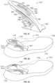
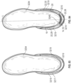
- FIG. 44 shows another embodiment of a heel spring device 2010 for an article of footwear 2012 shown in FIGS. 45-46 .
- the heel spring device 2010 has similar function and features as heel spring device 10.
- the device 2010 has a control bar 2014 with a medial side arm 2018 and a lateral side arm 2020.
- the device 2010 has a continuous base 2022 that connects the side arms 2018, 2020 and extends both forward and rearward from a junction of the control bar 2014 with the base 2022.
- the heel spring device 2010 is secured to the sole structure 2032 at its base 2022, and to the flexible covering of a footwear upper 1738 (shown in phantom), both of which are described with respect to FIG. 37 .
- the base 2022 underlies the foot-receiving void 1747, may underlie a strobel in the article of footwear 2012, may be secured to the sole structure 2032 by bonding with adhesive or otherwise, or may simply be trapped between sole structure 2032 and a strobel or upper materials to reduce the need for adhesive.
- FIG. 52 shows an article of footwear 2412 with another embodiment of a heel spring device 2410.
- the heel spring device 2410 has similar function and features as heel spring device 10.
- the device 2410 has a control bar 2414 with a medial side arm 18 and a lateral side arm 20, and a center segment 16 connecting the side arms 18, 20 and from which the side arms extend generally downwardly and forwardly.
- the device 2410 has a continuous base 22 that connects the side arms 18, 20 at first and second joints 24A, 24B, described with respect to FIG. 1 .
- the device 2410 is secured to a flexible footwear upper 2438 and to a sole structure 2432 similarly as described with respect to device 10.
- FIG. 54 shows an article of footwear 2612 with another embodiment of a heel spring device 2610.
- the heel spring device 2610 has similar function and features as heel spring device 2310.
- the device 2610 has a control bar 2614 with a series of slats 2681, and multiple slots 2680, best shown in FIG. 55 .
- Each slat 2681 has a center segment 2616, a medial side arm 2618 (best shown in FIG. 57 ) and a lateral side arm 2620.
- the lateral side arm 2620 and the medial side arm 2618 may be configured as mirror images of each other in one or more embodiments.
- the article of footwear 2612 includes a sole structure 2632 and a footwear upper 38 with a flexible covering which is described with respect to FIGS. 5-6 .
- the heel spring device 2610 is secured to the flexible covering of the footwear upper 38 via a strap 2633 that has a pocket 2635, as described with respect to FIGS. 59-60 .
- the control bar 2614 is biased to an unloaded position shown in FIG. 55 , and elastically bends under an applied force F to a loaded position shown in FIG. 56 , in which each center segment 2616 is closer to the base 2622 than in the unloaded position, storing potential energy that returns the control bar 2614 to the unloaded position upon removal of the applied force F.
- the control bar 2614 and the base 2622 are configured as a full elliptical leaf spring.
- the device 2610 may be a resiliently bendable nylon or another resiliently bendable material.
- the slots 2680 reduce the amount of material between an uppermost one 2681B of the slats and a lowermost one 2681A of the slats at the side arms as shown in FIG. 55 , and accordingly reduce the force required to bend the side arms. More specifically, with the slots 2680, the slats 2681 function as multiple thinner side arms that bend along their lengths in the region of the slots 2680.
- a lowermost one 2681A of the slats 2681 closest to the base 2622 at the center segment 2616 is shorter from its medial end 2682A to its lateral end 2683A than is an uppermost one 2681B of the slats 2681 from its medial end 2682B to its lateral end 2683B, where the uppermost slat 2681B is furthest from the base 2622.
- the medial ends 2682A, 2682B are indicated in FIG. 57 and are a mirror image of lateral ends 2683A, 2683B shown in FIG. 55 .
- the lowermost one of the slats 2681A is thinner than the uppermost one of the slats 2681B at any location along their lengths between the medial ends and the lateral ends, as is evident by comparing thickness T3 of the lowermost slat 2681A to thickness T4 of the uppermost slat 2681B in the exemplary embodiment of FIG. 55 .
- the thickness of slat 2681A may vary from its medial end to its lateral end
- the thickness of slat 2681B may vary from its medial end to its lateral end, at any given position between the medial end and the lateral end of slat 2681A
- the thickness of slat 2681A will be less than the thickness of slat 2681B along a line perpendicular to the longitudinal axis of slat 2681A.
- the slots 2680 enable the control bar 2614 to bend with less resistance (i.e., lower stiffness) than if the control bar 2614 were of the same overall thickness as the multiple slats 2681 from the uppermost slat 2681B to the lowermost slat 2681A.
- the slats 2681 can slide against (but not past) one another when they come into contact due to the slots 2680 closing, in a typical embodiment corresponding to Fig. 55 .
- the sliding enables further bending to continue at a reduced stiffness in comparison to a control bar configured in the manner of control bar 2614 but without slots.
- FIG. 56 shows a slight stagger at the rear of the stacked slats 2681, indicating that they have slid relative to one another with the slots 2680 closed.
- FIG. 55 shows the control bar 2614 biased to an unstressed (i.e., unloaded) position.
- FIG. 56 shows the control bar 2614 elastically bent under an applied force F (such as a force from a foot sliding into the article of footwear) to a loaded position, which will widen the ankle opening 39 of the upper 38 of FIG. 54 in comparison to the unloaded position as the upper 38 moves with the control bar 2614 in the heel region.
- F an applied force
- a heel region of the upper 38 rearward of the ankle opening 39 moves with the center section 2616 of the control bar closer to the base 2622 when the force F is applied, causing the ankle opening 39 to enlarge or at least change the position of the ankle opening such that it may tilt downward and rearward relative to the unloaded position and is accessible for foot entry in a downward and forward direction from the rear, rather than only downward, as best shown by comparing the position of the ankle opening 39 in FIG. 56 to the position of the ankle opening 39 in FIG. 55 .
- the upper 38 is connected to the heel spring device 2610 via an extension 2684 and a strap that has a pocket 2635.
- the lowermost slat 2681A has an extension 2684 extending from a lower edge 2685 of the center segment 2616.
- the extension 2684 extends at least partially downward from the center segment 2616, at least partially toward the base 2622.
- the extension 2684 extends downward and rearward when the control arm 2614 is in the unloaded position. In the loaded position of FIG. 56 , the extension points straighter downward than in the unloaded position.
- the control bar 2614 and the extension 2684 are configured to move clear of the base 2622 such that the extension is rearward of the base 2622 when the control arm 2614 is in the loaded position. No recess is needed in the base 2622 in such an embodiment.
- a strap 2633 has a proximal end 2633A sewn, integrally formed with, or otherwise connected to the upper 38 near the ankle opening 39 at the rear of the upper 38.
- the strap 2633 has a pocket 2635 at a distal end 2633B.
- the pocket 2635 may be formed, for example, by folding the strap 2633 over on itself at the distal end 2633B and stitching the folded portion to the remainder of the strap 2633.
- the strap 2633 extends downward from the upper 38.
- the strap 2633 is placed over and rearward of the control bar 2614, and the extension 2684 is then disposed in the pocket 2635 with the strap 2633 overlaying the center segment 2616.
- the extension 2684 and strap 2633 are thus used to operatively connect the upper 38 to the control bar 2614 so that the portion of the upper 38 rearward of the ankle opening 39 will move downward with the control bar 2614 to the loaded position, easing foot entry into the foot-receiving cavity of the upper 38 through the ankle opening 39, and then move back upward with the control bar to the unloaded position when the force F is removed, placing the upper 38 around the back of a foot that has been inserted into the foot-receiving cavity.
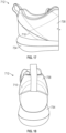
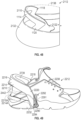
- FIG. 61 shows an article of footwear 2712 with another embodiment of a heel spring device 2710.
- the heel spring device 2710 has similar function and features as heel spring device 2610.
- the device 2710 has a control bar 2714 with a series of slats 2781, and multiple slots 2780 best shown in FIG. 63 .
- Each slat 2781 has a center segment 2716, a medial side arm 2718 (best shown in FIG. 62A ) and a lateral side arm 2720, best shown in FIG. 61 .
- the lateral side arm 2720 and the medial side arm 2718 are mirror images of each other.
- the device 2710 has the continuous base 2622, as described with respect to FIGS. 54 and 55 , that underlies the control bar 2714, and that connects the side arms and extends rearward from a junction of the control bar 2714 with the base 2622. As is evident from FIGS. 65 and 66 , the device 2710 has a concave inner surface 2711 with a concavity in both the medial-lateral and vertical directions.
- the slots 2780 reduce the amount of material between an uppermost one 2781B of the slats and a lowermost one 2781A of the slats at the side arms, and accordingly reduce the amount of force required to bend the side arms via the force F applied to the center segment 2616. More specifically, due to the slots 2780, the slats 2781 function as multiple thinner side arms that bend along their lengths in the region of the slots 2780. As shown in FIGS.
- a lowermost 2781A one of the slats 2781 closest to the base 2622 at the center segment 2716 is shorter from its medial end 2782A to its lateral end 2783A than is an uppermost one 2781B of the slats 2681 from its medial end 2782B to its lateral end 2783B, where the uppermost slat 2781B is furthest from the base 2622.
- the medial ends 2782A, 2782B are indicated in FIG. 62A and are a mirror image of lateral ends 2783A, 2783B.
- the lowermost one of the slats 2781A is thinner than any one of the other slats at a corresponding point (e.g., at a point directly aligned above the point along the lowermost one of the slats), as best shown in FIG. 63 .
- the thickness of a slat is measured along its longitudinal axis.
- slat 2781A may vary along its longitudinal axis from its medial end to its lateral end
- the thickness of slat 2781B may vary along its longitudinal axis from its medial end to its lateral end, at any given point between the medial end and the lateral end of slat 2781A
- the thickness of slat 2781A will be less than the thickness of slat 2781B at a point directly aligned above the point along slat 2781A.
- the slats 2781 are spaced apart from one another by the slots 2780 when the control bar 2714 is in the unloaded position of FIGS. 61-62A .
- the heel spring device 2710 includes a resilient insert 2790 that at least partially fills the slots 2780.
- the resilient insert 2790 may comprise a resiliently compressible material, such as at least one of rubber or thermoplastic polyurethane, and may be a foam, but is not limited to these materials.
- the resilient insert 2790 is a thermoplastic polyurethane foam that provides compressive stiffness and elastic resiliency. As best shown in FIG.
- the resilient insert 2790 includes a sleeve 2791 with spaced protrusions 2792 extending outward on an outer surface 2793 of the sleeve 2791.
- the sleeve 2791 is configured to extend along an inner side of the slats 2781 from the uppermost one 2781B of the slats 2781 to a lower periphery of the base 2622.
- An outer perimeter of the sleeve 2791 is coincident with an outer perimeter of the slats 2781 and base 2622.
- the spaced protrusions 2792 extend from the sleeve 2791 into the slots 2780 between the slats 2781.
- the spaced protrusions 2792 are shaped and dimensioned to completely fill the slots 2780 when the device 2710 is in the unloaded position of FIGS. 61 and 62A . In other embodiments, the spaced protrusions 2792 could be narrower than the slots 2780.
- the spaced protrusions 2792 may be flush with the outer surfaces of the slats 2781, or may extend outward beyond the outer surfaces of the slats 2781.
- the slats 2781 and base 2622 may be referred to as a cage which supports the insert 2790.
- the slots 2780 partially close between the slats 2781 when a downward force F is applied to the control bar 2714, moving the control bar 2714 to the loaded position of FIG. 62B so that the adjacent center segments 2716 move closer to one another and the protrusions 2792 are partially compressed between the slats 2781.
- the sleeve 2791 also compresses as it moves downward with the control bar 2714. Because the sleeve 2791 and/or the slats 2781 are operatively secured to the heel portion of the flexible covering of the upper 38 rearward of the ankle opening 39, the upper 38 moves downward with the sleeve 2791 and control bar 2714 to the loaded position.
- the amount of force required to move the device 2710 from the unloaded position to the loaded position is thus dependent on both the bending stiffness of the control arm 2714 and the compressive stiffness of the resilient insert 2790 in the slots 2780.
- the compressive stiffness of the insert 2790 is less than the bending stiffness of the slats 2781, and therefore enables the control bar 2714 to bend with a lower force F than if the control bar 2714 were of the same overall thickness as the multiple slats 2781 from the uppermost slat 2781B to the lowermost slat 2781A (i.e., if the control bar 2714 had no slats).
- the article of footwear 2712 includes the sole structure 2632 and the footwear upper 38 with a flexible covering.
- the heel spring device 2710 is secured to the flexible covering of the footwear upper 38 with adhesive, stitching, thermal bonding, or otherwise so that a rear portion of the upper 38 rearward of the ankle opening 39 moves with the heel spring device 2710.
- the heel spring device 2710 is also secured to the sole structure 2632 at its base 2622 by the flange 2632A of the sole structure 2632 secured in the peripheral recess 2622A.
- the control bar 2714 is biased to an unloaded position shown in FIG. 62A , and elastically bends under an applied force F to a loaded position shown in FIG. 62B .
- each center segment 2716 is closer to the base 2622 than in the unloaded position due to the arms 2718, 2720 bending and storing potential energy that returns the control bar 2714 to the unloaded position upon removal of the applied force F.
- the control bar 2714 and the base 2622 are configured as a full elliptical leaf spring.
- the slats 2781 and base 2622 may be nylon or another resiliently bendable material.
- FIG. 62A shows the control bar 2714 biased to an unstressed (i.e., unloaded) position.
- FIG. 62B shows the control bar 2714 elastically bent under an applied force F (such as a force of a foot sliding into the article of footwear) to a loaded position, which will widen the ankle opening 39 of the upper 38 of FIG. 61 in comparison to the unloaded position, as the upper 38 moves with the control bar 2714 in the heel region.
- F such as a force of a foot sliding into the article of footwear
- a heel region of the upper 38 rearward of the ankle opening 39 moves with the center section 2716 of the slats 2781 closer to the base 2622 when the force F is applied, causing the ankle opening 39 to enlarge or at least change position by lowering the upper 38 rearward of the ankle opening 39 such that the ankle opening 39 may tilt downward and rearward relative to the unloaded position and is accessible for foot entry of a foot moving in a downward and forward direction from the rear.
- the slats 2781 and base 2622 may be injection molded. Once molded, the slats 2781 and base 2622 are a single, unitary component. The material of the foam insert 2790 may then be injected into a mold cavity containing the molded slats 2781 and base 2622.
- FIG. 66 shows apertures 2794 (only some of which are numbered) where pins hold the slats 2781 and base 2622 against a surface of the mold while the material of the insert 2790 is injected.
- the insert 2790 is molded around ribs 2795 of the base 2622 near the junctions of the slats 2781 with the base 2622, as indicated by slots 2796 in the insert 2790 in FIG. 64 .
- FIG. 67 shows an article of footwear 2712A with another embodiment of a heel spring device 2710A.
- the heel spring device 2710A is alike in all aspects as heel spring device 2710, except that the insert 2790 has protrusions 2792A that are configured as bellows that extend outward and fill slots between the slats 2781 between the slats 2781 from an inner side of the slats 2781.
- the slats 2781 and base 2622 may be formed of a semi-rigid or rigid thermoplastic polyurethane, while the insert 2790 with protrusions 2792A may be formed of a softer thermoplastic polyurethane relative to the slats 2781 and base 2622.
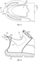
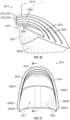
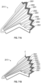
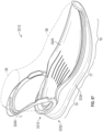
- FIG. 68 shows an article of footwear 2812 with another embodiment of a heel spring device 2810.
- the heel spring device 2810 has a similar function as heel spring device 2710, but is comprised of an elastic corrugated body 2815 including a center segment 2816, a medial side arm 2818 (best shown in FIG. 69 ) extending downwardly and forwardly from the center segment 2816, and a lateral side arm 2820 (best shown in FIG. 68 ) extending downwardly and forwardly from the center segment 2816.
- the corrugated body 2815 includes alternating ridges 2881 and grooves 2880 that extend lengthwise along the medial side arm 2818, the center segment 2816 and the lateral side arm 2820. As is evident from FIGS. 70 and 71A , the device 2810 has a concavity at an inner surface in both the medial-lateral and vertical directions.
- the corrugated body 2815 is biased to an unloaded position shown in FIGS. 68, 69 , 70 and 71A .
- the corrugated body 2815 compresses under an applied force F to a loaded position shown in FIG. 71B .
- the corrugated body 2815 compresses (e.g., by folding) so that adjacent ones of the alternating ridges 2881 are closer to one another than in the unloaded position, particularly at the center segment 2816, storing elastic energy that returns the corrugated body 2815 to the unloaded position upon removal of the applied force F.
- the upper 38 moves with the center segment 2816 such that the ankle opening 39 may tilt downward and rearward relative to the unloaded position when the heel spring device 2810 is in the loaded position.
- a first set of the ridges 2881A and grooves 2880A extend from the medial side arm 2818 to the lateral side arm 2820, and a second set of the ridges 2881B and grooves 2880B extend only along the center segment 2816.
- the first and second sets are configured so that the ridges and grooves can follow the contours of the upper 38, extending along the entire portion of the upper 38 rearward of the ankle opening 39, while still allowing some of the grooves and ridges (i.e., the first set) to extend downwardly and forwardly.
- the device 2810 may include an upper flange 2823 extending along an upper edge 2825 of the corrugated body 2815 at the center segment 2816, and further comprises a lower flange 2822 extending along a lower edge 2827 of the corrugated body 2815 at the medial arm 2818, the center segment 2816, and the lateral arm 2820.
- the lower flange 2822 is also referred to as a base.
- the sole structure 2632 is secured to the lower flange 2822 by adhesive, thermal bonding, or otherwise, so that the sole structure 2632 generally underlies the upper 38 and the heel spring device 2810 as shown in FIG. 68 .
- the outer surface of the base 2822 has a peripheral recess 2822A extending from a lower edge 2822B of the base 2822.
- the sole structure 2632 has a flange 2632A configured to be seated in the peripheral recess 2822A.
- the flange 2632A of the sole structure 2632 provides lateral support to the heel spring device 2810.
- the upper flange 2823 is stitched to the upper 38 rearward of the ankle opening 39 as shown by stitches 2829 in FIG. 68 .
- the upper flange 2823 may alternatively be adhered or thermally bonded to the upper 38.
- the connection of the heel spring device 2810 to the upper 38 via the upper flange 2823 enables the upper 38 to move with the heel spring device 2810 between the loaded and unloaded positions.
- the ridges 2881 and grooves 2880 of the corrugated body 2815 may also be referred to as bellows.
- the ridges 2881 are pleats of the bellows and the grooves 2880 are folds of the bellows.
- the device 2810 is a one-piece, unitary component that includes the corrugated body 2815 and the flanges 2822, 2823.
- the device 2810 may be injection molded of an elastically deformable material, such as at least one of rubber or thermoplastic polyurethane, and may be a resilient foam (e.g., a polymer foam material, etc.), but is not limited to these materials.
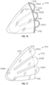
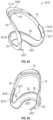
- FIG. 72 shows another embodiment of a heel spring device 2910 within the scope of the present teachings.
- the heel spring device 2910 has the spaced slats 2781 and a base 2622 as described with respect to the heel spring device 2710, and is biased to the unloaded position shown in FIG. 72 , but elastically bends to a loaded position (not shown) in response to an applied load, which helps to open an ankle opening of an upper to ease foot entry as described with respect to heel spring device 2710.
- the heel spring device 2910 includes discrete resilient inserts 2990 disposed in the slots 2780 but only along a portion of the center segments 2716 (e.g., not in the slots of the side arms).
- a strap 2991 is adhered or otherwise connected to the inserts 2990 and to the slats 2781 to retain the inserts 2990 in position within the slots 2780.
- the strap 2991 may be an integral portion of the resilient inserts 2990 such that the resilient inserts 2990 are integrated as a unitary component.
- FIG. 73 shows another embodiment of a heel spring device 3010.
- the heel spring device 3010 has the spaced slats 2781 and the base 2622 as described with respect to the heel spring device 2710, and is biased to the unloaded position shown in FIG. 73 , but elastically bends to a loaded position (not shown) which helps to open an ankle opening of an upper to ease foot entry as described with respect to heel spring device 2710.
- the heel spring device 3010 has a pair of intermediate slats 3083 arranged as an elliptical spring between the base 2622 and a middle one of the slats 2781 and connected to the base 2622 and the middle slat 2781, respectively.
- the heel spring device 3010 also has a pair of intermediate slats 3085 arranged as an elliptical spring between the uppermost slat and the middle one of the slats 2781, and connected to the uppermost slat and the middle slat, respectively.
- the intermediate slats 3083, 3085 provide additional resistance to bending and stored elastic energy to return the heel spring device 3010 to the unloaded position upon removal of the applied load.
- the arrangement of slats 2781 and intermediate slats 3083, 3085 may be referred to as a lattice.
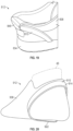
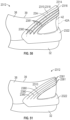
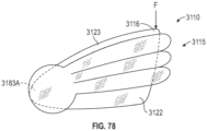
- FIG. 74 shows an article of footwear 3112 with another embodiment of a heel spring device 3110.
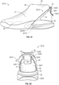
- the heel spring device 3110 has a similar function as heel spring device 2610, but is comprised of a fluid-filled bladder 3115 including a center segment 3116, a medial side arm 3118 (shown in FIG. 75 ) extending downwardly and forwardly from the center segment 3116, and a lateral side arm 3120 extending downwardly and forwardly from the center segment 3116.
- the sole structure 2632 is secured to a lower flange 3122 of the bladder element 3115 by adhesive, thermal bonding, or otherwise, so that the sole structure 2632 generally underlies the upper 38 and the heel spring device 3110 as shown in FIG. 74 .
- the center segment 3116 moves the bladder element 3115 from an unloaded position ( FIG. 77 ) to a loaded position ( FIG. 78 ).
- the unloaded position is also referred to as an expanded position, and the loaded position is also referred to as a collapsed or compressed position.
- the center segment 3116 may be referred to as a control bar.
- the bladder element 3115 may be thermoformed from a first polymeric sheet 3117 and a second polymeric sheet 3119 (best shown in FIG. 76 and also referred to as an inner and an outer sheet, or an inner and an outer layer, respectively). Alternatively, the bladder element 3115 may be blow-molded from a pre-form polymeric material.
- the bladder element 3115 can be formed from any of various polymeric materials that retain a fluid at a predetermined pressure, including a fluid that is a gas, such as air, nitrogen, or another gas.
- a "fluid” includes a gas, including air, an inert gas such as nitrogen, or another gas. Accordingly, "fluid-filled” includes "gas-filled”.
- the bladder element 3115 can be a TPU material, a urethane, polyurethane, polyester, polyester polyurethane, and/or polyether polyurethane.
- the bladder element 3115 can be formed from sheets having layers of different materials.
- the sheets 3117, 3119 may be laminate membranes formed from thin films having one or more first layers that comprise thermoplastic polyurethane layers and that alternate with one or more second layers, also referred to herein as barrier layers, gas barrier polymers, or gas barrier layers.
- the second layers may comprise a copolymer of ethylene and vinyl alcohol (EVOH) that is impermeable to the pressurized fluid contained therein as disclosed in U.S. Patent No. 6,082,025 to Bonk et al.
- EVOH ethylene and vinyl alcohol
- the first layer may be arranged to form an outer surface of the polymeric sheet. That is, the outermost first layer may be the outer surface of the bladder element 3115.
- the bladder element 3115 may also be formed from a material that includes alternating layers of thermoplastic polyurethane and ethylene-vinyl alcohol copolymer, as disclosed in U.S. Patent Nos. 5,713,141 and 5,952,065 to Mitchell et al. which are incorporated by reference in their entireties.
- the layers may include ethylene-vinyl alcohol copolymer, thermoplastic polyurethane, and a regrind material of the ethylene-vinyl alcohol copolymer and thermoplastic polyurethane.
- the sheets 3117, 3119 may have alternating layers of thermoplastic urethane (TPU) and a gas barrier material. In the embodiment shown, the sheets 3117, 3119 are transparent.
- the sheets 3117, 3119 are bonded to one another at a periphery of the bladder element 3115, such as at an upper flange 3123 and the lower flange 3122, also referred to as a base.
- the lower flange 3122 is continuous and is connected to and supports the medial side arm 3118, the center segment 3116, and the lateral side arm 3120.
- the sheets 3117, 3119 are also bonded to one another at various intermediate bond locations 3124, referred to as webbing.
- the upper flange 3123 is thermally bonded, adhered, or otherwise secured to the upper 38 rearward of the ankle opening 39 as shown in FIG. 74 .
- the upper 38 may also be secured to the inner surface of the first polymeric sheet 3117 between the upper and lower flanges 3123, 3122.
- the connection of the heel spring device 3110 to the upper 38 via the upper flange 3123 enables the upper 38 to move with the heel spring device 3110 between the loaded and unloaded positions. More specifically, the upper 38 moves with the center segment 3116 such that the ankle opening 39 may tilt downward and rearward relative to the unloaded position when the heel spring device 3110 is in the loaded position, enabling hands-free foot entry.
- the bonded sheets 3117, 3119 form various fluid-filled interior cavities 3181A, 3181B, 3181C, 3183A, and 3183B which are fluid-tight, and may be pressurized or unpressurized.
- the fluid-filled interior cavities 3181A, 3181B, 3181C, 3183A, and 3183B are at the ambient pressure of the environment in which the fluid-filled cavities were sealed.
- the fluid-filled interior cavities 3181A, 3181B, 3181C, 3183A, and 3183B could be pressurized by fluid introduced into the cavities through one or more inflation ports (not shown) that are then sealed.
- each of the fluid-filled interior cavities 3181A, 3181B, and 3181C is generally tubular, and extends lengthwise along the medial side arm 3118, the center segment 3116, and the lateral side arm 3120.
- the cavities 3181A, 3181B, 3181C only extend along the center segment 3116.
- the cavities 3181A, 3181B, 3181C may be referred to as elongated cavities or tubular cavities.
- fluid-filled cavities of other shapes may extend along the center segment 3116, and may also extend along either or both of the medial side arm and the lateral side arm.
- multiple discrete cavities shaped as tubes that are shorter than the cavities 3181A, 3181B, 3181C, or having other shapes, may extend along the center segment 3116 and may be fluidly-interconnected to one another by channels formed by the sheets.
- the tubular cavities 3181A, 3181B, and 3181C are connected with and in fluid communication with the fluid-filled interior cavities 3183A, 3183B, which may be referred to as a medial reservoir 3183A and a lateral reservoir 3183B. In this manner, the tubular cavities 3181A, 3181B, and 3181C are indirectly in fluid communication with one another via the reservoirs 3183A, 3183B. In some embodiments, channels extending directly between adjacent ones of the tubular cavities 3181A, 3181B, and 3181C may also be provided such that the tubular cavities 3181A, 3181B, 3181C are in direct fluid communication with one another.
- the tubular cavities 3181A, 3181B, and 3181C simply end on the side arm that does not have a reservoir.
- each of the tubular cavities may have its own separate reservoir on either or both of the side arms.
- the reservoirs 3183A, 3183B are formed by the first and second polymeric sheets 3117 and 3119 at medial and lateral extremities of the tubular cavities 3181A, 3181B, and 3181C, respectively.
- the device 3110 has a concavity at the inner surface of the first polymeric sheet in both the medial-lateral and vertical directions.
- Some of the fluid within the fluid-filled interior cavities 3181A, 3181B, and 3181C may be displaced to the reservoirs 3183A, 3183B as the tubular cavities 3181A, 3181B, and 3181C are compressed, causing the reservoirs to expand and bulge outward, as represented in FIG. 78 at reservoir 3183A.
- the resiliently deformed bladder element 3115 returns to the unloaded position of FIG. 77 as the displaced fluid returns from the reservoirs 3183A, 3183B to the tubular cavities 3181A, 3181B, and 3181C upon removal of the applied force F, expanding the tubular cavities 3181A, 3181B, 3181C to their original shapes and reducing the sizes of the reservoirs 3183A, 3183B to their original shapes.
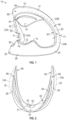
- FIG. 79 shows another embodiment of a heel spring device 3210 for an article of footwear 3212 shown in FIGS. 80-82 .
- the heel spring device 3210 has similar function and features as heel spring device 10.
- the device 3210 has the control bar 14 with the medial side arm 18 and lateral side arm 20.
- the device 3210 has the continuous base 22 that connects the side arms 18, 20 and extends rearward from a junction of the control bar 14 with the base 22.
- the base 22 underlies the control bar 14 with the first side arm 18 at a medial side 41 of a footwear upper 38, the second side arm 20 at a lateral side 43 of the footwear upper 38, and the center segment 16 of the control bar 14 rearward of the ankle opening 39 of the footwear upper 38.
- the base 22 supports the control bar 14 and is connected to the control bar 14 at resiliently bendable junction 3224A, 3224B.
- the base 22 is continuous and extends between and connects to the first side arm 18 and the second side arm 20.
- the base 22 is continuous in that it is without breaks or connections through other components in extending from the first side arm 18 to the second side arm 20.
- the base 22 has a center segment 26, a first base arm 28, and a second base arm 30 all disposed in a common plane, as described with respect to the device 10 of FIG. 3 .
- the first base arm 28 is spaced apart from the second base arm 30 and both extend from the center segment 26 of the base 22.
- the junction 3224A, 3224B includes a first joint 3224A at which the base 22 and the first side arm 18 connect, and a second joint 3224B at which the base 22 and the second side arm 20 connect.
- the first joint 3224A is the connection of the first base arm 28 to the first side arm 18.
- the second joint 3224B is the connection of the second base arm 30 to the second side arm 20.
- the joints 3224A, 3224B may be referred to herein as hinged joints, or as a hinged junction.
- the control bar 14 has an arced shape from the first joint 3224A to the second joint 3224B.
- the base 22 has an arced shape from the first joint 3224A to the second joint 3224B.
- the control bar 14 and the base 22 are configured as a full elliptical leaf spring as described herein.
- the device 3210 may be referred to as a heel spring.
- the device 3210 is a single, unitary, one-piece component.
- the device 3210 may be injection molded as a single, unitary, one-piece component.
- the center segment 16 of the control bar 14 has the ramped surface 50 that declines toward an inner periphery of the center segment 16 between the first side arm 18 and the second side arm 20 and helps direct the foot downward and forward into the foot-receiving cavity 47 during application of the downward force F on the control bar 16 as described with respect to device 10. Additionally, the first side arm 18 and the second side arm 20 are each twisted outwardly along their respective longitudinal axis from the junction 3224A, 3224B near the base 22 to the center segment 16 of the control bar 14. The outward twist helps to encourage the down and back movement of the center segment 16 during loading by the foot.
- the article of footwear 3212 includes a sole structure 3232, and the flexible footwear upper 38 has a medial side 41 and a lateral side 43, and defines an ankle opening 39 and a foot-receiving cavity 47, as described with respect to the article of footwear 12.
- the sole structure 3232 includes one or more sole components that may be sole layers, such as an outsole, a midsole, or a sole layer 3234 that is a unitary combination of an outsole and a midsole and may be referred to as a unisole.
- the sole layer 3234 underlies the upper 38 and the foot-receiving cavity 47 defined by the upper 38.
- a lower portion 40 of the footwear upper 38 is secured to the sole layer 3234, such as by adhesive or otherwise.
- the base 22 is secured to the sole layer 3234 such as by bonding with adhesive, thermal bonding, or otherwise.
- the sole layer 3234 has a slight recess 3219 in the outer wall 3217 of the sole layer 3234 (i.e., in the outer side walls and rear wall in the heel region of the sole layer 3234).
- the recess 3219 is shaped to allow the base 22 and joints 3224A, 3224B to partially nest in the recess 3219.
- the portions of the base 22 and the joints 3224A, 3224B nested in the recess 3219 are secured to the outer wall 3217 of the sole layer 3234 in the recess 3219.
- the device 3210 is thus supported by the sole layer 3234 in the recess 3219.
- the control bar 14 is biased to an unloaded position shown in FIGS. 80 and 82 .
- the unloaded position is also referred to herein as an unstressed position.
- the control bar 14 is internally biased to the unstressed position by its material in its formed state. Stated differently, the material of the control bar 14 is sufficiently rigid that it remains in the unstressed position in its natural state without external loads applied to it, and will return to the unstressed position after elastic bending due to its resiliency.
- the center segment 16 is a first distance D1 from the bottom of the center segment 26 of the base 22, as indicated in FIG. 80 by a distance D1 from the top of the center segment 16 of the control bar 14 to the bottom of the center segment 26 of the base 22.
- the unstressed position is the position of the device 3210 in a relaxed, unloaded state (i.e., without a vertical force applied to the control bar 14).
- the control bar 14 can be depressed under an applied force F shown in FIG. 80 , representing the force applied by a foot during insertion of the foot into the foot-receiving cavity 47 (see, e.g., FIGS. 5 and 6 ) of the article of footwear 3212.
- F shown in FIG. 80
- the control bar 14 elastically bends to a loaded position in which the top of the center segment 16 is a second distance D2 from the bottom of the center segment 26 of the base 22.
- the loaded position is shown in FIG.
- the second distance D2 is less than the first distance D1.
- the difference between the distances D1 and D2 is the deflection of the device 3210, which may be but is not limited to a deflection of 30 mm.
- the device 3210 is configured so that when it is depressed under the force F to the loaded position D2, it elastically bends at the junction 3224A, 3224B, storing elastic energy. When the force F is removed, the stored elastic energy returns the control bar 14 to the unstressed position.
- first side arm 18 and the second side arm 20 extend at a first acute angle A1 to the common plane P of the base 22 when the control bar 14 is in the unloaded position.
- the first side arm 18 and the second side arm 20 extend at a second acute angle A2 to the common plane P of the base 22 when the control bar 14 is depressed.
- the second acute angle A2 is less than the first acute angle A1.
- the base 22 extends around a rearmost portion of the footwear upper 38 from the lateral side 43 to the medial side 41.
- the device 3210 is not secured to the upper 38 at the medial side 41 or the lateral side 43. Instead, the device 3210 is only secured to the upper 38 via a heel tab 3249 that extends through an aperture 3245 in the center segment 16. The tab 3249 is then stitched to a rear portion 3247 of the upper 38 at stitching 3241.
- a decorative snap 3243 may be secured to the tab 3249. However, in the embodiment shown, the decorative snap 3243 is merely decorative in that it does not snap or otherwise fasten to the upper 38.
- FIG. 84 best illustrates that the medial side arm 18 and the lateral side arm 20 are asymmetrical about a longitudinal axis L extending between the medial side arm 18 and the lateral side arm 20 through the base 22.
- the medial side arm 18 is also referred to herein as a first side arm
- the lateral side arm 20 is also referred to as a second side arm.
- the medial side arm 18 may be shorter than the lateral side arm 20 and may be have a greater lateral (i.e., outward) curvature than the lateral side arm, similar to the shape of a typical heel region of a foot. Because the heel device 3210 is asymmetrically shaped in this manner following a typical foot shape, pressure of the heel device 3210 against the sides of the foot during wear is thus minimized.
- FIGS. 85-86 illustrate another embodiment of a heel spring device 3310 that has many of the same features as heel spring device 10, 3210, which features are referenced with like reference numbers. Additionally, the base 22 has an inwardly-extending flange 3221 that extends continuously from the medial base side arm 28, around the center segment 26 to the lateral base side arm 30 such that the flange 3221 generally has a U-shape.
- the heel spring device 3310 is included in an article of footwear 3312 that has an upper 38 and a sole structure 3332.
- the upper 38 is as described herein with respect to heel spring device 10, and is shown only in phantom in FIG. 87 .
- the sole structure 3332 includes an outer sole layer 3334 that may serve as a unitary outsole and midsole.
- the sole structure 3332 also includes an inner sole layer 3345, also referred to as an insole, that overlays the sole layer 3334.
- FIG. 89 shows the sole layer 3334 alone with the inner sole layer 3345 removed.
- the sole layer 3334 has a recess 3349 in an upper surface 3347.
- the recess 3349 is shaped so that the flange 3221 is seated in and at least partially nested in the recess 3349, and secured to the upper surface 3347 in the heel region of the sole structure 3332.
- FIG. 90 shows the flange 3221 seated in the recess 3349.
- the heel spring device 3310 is secured to the sole layer 3334 by securing the flange 3221 to upper surface 3347 of the sole layer 3334 in the recess 3349 by thermal bonding, by adhesive, or otherwise.
- the inner sole layer 3345 is then inserted in the upper 38 to rest on the sole layer 3334 over the flange 3221 and at the upper surface 3347 of the sole layer 3334.
- the heel spring device 3310 is asymmetric about the longitudinal axis L. More specifically, the medial side arm 18 curves laterally outward more than the lateral side arm 20, and is also longer in a fore-aft direction (along the longitudinal axis L) than the lateral side arm 20. As discussed with respect to heel spring device 3210, this is a more anatomical shape than a symmetrical heel spring device, and avoids undesirable friction and pressure of the side arms 18, 20 on the foot.
- the heel spring device 3310 is configured to secure to the upper 38 at forwardmost portions of the side arms 18, 20, and via a heel tab extending through an aperture 3245 of the center segment 16 as indicated with respect to the upper 38 shown in phantom in FIG. 87 . More specifically, a forwardmost portion 3371 of an inner surface 3373 of the first side arm 18 includes a medial recess 3374 such that the first side arm 18 is thinner at the medial recess 3374 than rearward of the medial recess 3374. A forwardmost portion 3375 of an inner surface 3377 of the second side arm 20 includes a lateral recess 3376 such that the second side arm 20 is thinner at the lateral recess 3376 than rearward of the lateral recess 3376.
- the upper 38 may be secured to the first side arm 18 at the medial recess 3374 and to the second side arm 20 at the lateral recess 3376.
- the upper 38 may be bonded to the side arms 18, 20 at the recesses 3374, 3376.
- the upper may include an inner portion 38B, and an outer portion 38A, as shown in FIG. 88 .
- the outer portion 38A may include rearward-extending flanges 38C that are thinner than more forward portions of the outer portion 38A.
- the flanges 38C interfit with and are secured to the inner surfaces 3373, 3377 of the side arms 18, 20 in the recesses 3374, 3376.
- the outer portion 38A may be less flexible than the inner portion 38B, and may thus provide better anchoring support to the device 3310 at the arms 18, 20 than would the inner portion 38B.
- the upper 38 may be secured to the heel spring device 3310 via a heel tab 3249 (see FIGS. 87 and 91 ).
- the heel tab 3249 extends through an aperture 3245 in the center segment 16. After the tab 3249 is extended through the aperture 3245, the tab 3249 may be folded over in a loop and stitched to itself at stitching 3285 as shown in FIG. 92 .
- a pin 3283 may then be inserted into an opening 3281 in the loop of the tab 3249.
- the pin 3283 may be secured to the tab 3249 in the opening 3281 rearward of the aperture 3245, such as by inserting adhesive into the opening 3281.
- the tab 3249 with the pin 3283 therein may be wider than the aperture 3245.
- the pin 3283 has a width 3286 (see FIG. 91 ) which is greater than the width 3287 of the aperture 3245.
- FIGS. 93-94 show a heel spring device 3410 that has many of the same features as heel spring devices 10 and 3210. Like reference numbers are used to refer to such features.
- the device 3410 includes a lever 3489 that extends laterally outward from the control bar 14.
- the lever 3489 may also be referred to as a ledge extension or a shelf.
- the lever 3489 is disposed partly along the medial side arm 18 and partly along the center segment 16. Within the scope of the present disclosure, the lever 3489 may be disposed anywhere along the control bar 14.
- the lever 3489 has an upward-facing surface 3491 that may be depressed downward, in a similar manner as described with respect to force F on the center segment 16 in FIG. 80 .
- FIG. 94 shows a rear view of an article of footwear 3412 that includes the device 3410 secured to a sole layer 3434 and to the upper 38.
- heel spring devices enhance the ease of foot entry, allowing hands free foot entry into an article of footwear.
- a device configured to surround a portion of a foot-receiving cavity at a heel region of an article of footwear, the device comprising a control bar having a center segment, a first side arm extending from the center segment, and a second side arm spaced from the first side arm and extending from the center segment; a continuous base supporting the control bar and connected to both of the first side arm and the second side arm; and wherein the control bar is biased to an unstressed position with the center segment a first distance from the base, the control bar elastically deforms under an applied force to a loaded position with the center segment a second distance from the base less than the first distance, and the device stores potential energy that returns the control bar to the unstressed position upon removal of the applied load.
- Clause 2 The device of Clause 1, wherein the base is connected to the first side arm at a first j oint, and the base is connected to the second side arm at a second joint.
- Clause 3 The device of Clause 2, wherein: the control bar has an arced shape from the first joint to the second joint; the base has an arced shape from the first joint to the second joint; and the control bar and the base are configured as a full elliptical leaf spring.
- Clause 4 The device of any of Clauses 2-3, wherein: the base has a center segment, a first base arm, and a second base arm all disposed in a common plane; the first base arm is spaced apart from the second base arm and both extend from the center segment of the base; the first base arm and the first side arm are connected at the first joint; the second base arm and the second side arm are connected at the second joint; the first side arm and the second side arm extend at an acute angle to the common plane of the base when the control bar is in the unstressed position; the first side arm and the second side arm extend at a second acute angle to the common plane of the base when the control bar is in the loaded position; and the second acute angle is less than the first acute angle.
- Clause 5 The device of any of Clauses 1-4, wherein the center segment of the control bar has a ramped surface that declines toward an inner periphery of the center segment between the first side arm and the second side arm.
- Clause 6 The device of any of Clauses 1-5, wherein the first side arm and the second side arm are each twisted outwardly along their respective longitudinal axis from the base to the center segment of the control bar.
- Clause 7 The device of any of Clauses 1-6, wherein the first side arm and the second side arm are asymmetrical about a longitudinal axis extending between the first side arm and the second side arm through the base.
- Clause 8 The device of any of Clauses 1-7, wherein the base has an inwardly-extending flange.
- Clause 9 The device of Clause 8 in combination with a footwear sole structure having a foot-receiving surface with a recess in a heel region; and wherein the flange is seated in the recess and secured to the foot-receiving surface.
- Clause 10 The device of any of Clauses 1-7 in combination with a footwear sole structure having an outer wall with a recess in a heel region; and wherein the base of the device at least partially nests in the recess and is secured to the outer wall of the sole structure.
- Clause 11 The device of any of Clauses 1-10 in combination with a footwear upper that defines at least a portion of an ankle opening, wherein the base underlies the control bar with the first side arm at a medial side of the footwear upper, the second side arm at a lateral side of the footwear upper, and the center segment of the control bar rearward of the ankle opening.
- Clause 12 The device of Clause 11, wherein a forwardmost portion of an inner surface of the first side arm includes a medial recess such that the first side arm is thinner at the medial recess than rearward of the medial recess, and a forwardmost portion of an inner surface of the second side arm includes a lateral recess such that the second side arm is thinner at the lateral recess than rearward of the lateral recess; and wherein the upper is secured to the second side arm at the lateral recess, and to the first side arm at the medial recess.
- Clause 13 The device of any of Clauses 1-12, wherein the center segment has an aperture; and wherein the footwear upper includes a tab that extends through the aperture.
- Clause 14 The device of Clause 13, wherein the tab is secured to a rear portion of the footwear upper.
- Clause 15 The device of Clause 13, further comprising: a pin secured to the tab rearward of the aperture, wherein the tab with the pin thereon is wider than the aperture such that the tab is anchored to the center segment by the pin.
- Clause 16 The device of any of Clauses 1-15, further comprising: a lever extending outward from the control bar.
- Clause 17 The device of any of Clauses 1-16, wherein the first side arm and the second side arm each have at least one slot extending therethrough.
- Clause 18 The device of Clause 17, wherein the control bar includes a series of slats each extending along the first side arm, the center segment, and the second side arm, and wherein the at least one slot includes a series of slots, each extending along the first side arm, the center segment, and the second side arm and disposed between respective adjacent ones of the slats.
- Clause 19 The device of any of Clauses 1-16, wherein the device comprises a bladder element including one or more fluid-filled interior cavities.
- Clause 20 The device of Clause 19, wherein: the one or more fluid-filled interior cavities include: cavities extending along the center segment; and one or more reservoirs disposed at either or both of the first side arm and the second side arm and in fluid communication with the cavities extending along the center segment; and the one or more reservoirs expand with fluid displaced from the cavities extending along the center segment when the heel spring device resiliently deforms under the applied force.
- the one or more fluid-filled interior cavities include: cavities extending along the center segment; and one or more reservoirs disposed at either or both of the first side arm and the second side arm and in fluid communication with the cavities extending along the center segment; and the one or more reservoirs expand with fluid displaced from the cavities extending along the center segment when the heel spring device resiliently deforms under the applied force.
- Clause 21 The device of any of Clauses 1-18, wherein the first side arm and the second side arm bow apart from one another when the control bar is in the loaded position.
- Clause 22 The device of any of Clauses 1-18, wherein: one of the control bar and the base has an extension that extends toward the other of the control bar and the base; and the extension is spaced apart from the other of the control bar and the base when the control bar is in the unstressed position, and contacts the other of the control bar and the base when the control bar is in the loaded position, limiting further depression of the control bar.
- Clause 23 The device of Clause 22, wherein: the extension extends from the center segment of the control bar toward the base; the base has a recess; and the extension is spaced apart from the base when the control bar is in the unstressed position, and protrudes into the recess when the control bar is in the loaded position.
- Clause 24 The device of Clause 11, wherein the control bar is embedded within the footwear upper.
- Clause 25 The device of Clause 11, wherein the base has a forward-extending protrusion underlying the foot-receiving void adjacent the medial side of the footwear upper, and a rearward extending protrusion underlying the foot-receiving void along the lateral side of the footwear upper.
- Clause 26 The device of Clause 1, wherein the base couples to forwardmost portions of the first side arm and the second side arm.
- Clause 27 The device of Clause 1, wherein the base extends rearward from the control bar.
- Clause 28 The device of Clause 1, wherein the base extends forward from the control bar.
- Clause 29 The device of Clause 1, wherein the base is a sole structure of an article of footwear.
- Clause 30 The device of Clause 1, wherein the base is a flexible footwear upper.
- Clause 31 The device of any of Clauses 1-30, wherein the device is a single, unitary, one-piece component.
- a device for easing foot entry into an article of footwear and configured to surround a portion of a foot-receiving cavity at a heel region of an article of footwear comprising: a control bar and a base underlying the control bar; wherein the control bar includes a series of slats each having: a center segment; a medial side arm extending from the center segment to a medial end connected to a medial side of the base; and a lateral side arm extending from the center segment to a lateral end connected to a lateral side of the base; and wherein the control bar is biased to an unloaded position and elastically bends under an applied force to a loaded position in which at least one center segment is closer to the base than in the unloaded position, storing potential energy that returns the control bar to the unloaded position upon removal of the applied load.
- Clause 33 The device of Clause 32, wherein the control bar and the base are configured as a full elliptical leaf spring.
- Clause 34 The device of any of Clauses 32 and 33, wherein: the control bar defines slots extending between the slats; the slats are spaced apart from one another by the slots when the control bar is in the unloaded position; and one or more of the slots close between the slats so that one or more adjacent center segments contact one another in the loaded position.
- Clause 35 The device of Clause 34, wherein: the slots are parallel with one another; and exterior sides of the slats are flush with one another in the unloaded position.
- Clause 36 The device of any of Clauses 32-35, wherein a lowermost one of the slats closest to the base at the center segment is shorter from the medial end to the lateral end than an uppermost one of the slats furthest from the center segment; and wherein the lowermost one of the slats is thinner than the uppermost one of the slats.
- Clause 37 The device of any of Clauses 32-36, wherein a lowermost one of the slats has a tab extending from a lower edge of the center segment.
- Clause 38 The device of any of Clauses 32-37, wherein an outer surface of the base has a peripheral recess extending from a lower edge of the base.
- Clause 39 The device of any of Clauses 32-38, further comprising: a resilient insert at least partially filling the slots.
- Clause 40 The device of Clause 39, wherein the resilient insert includes: a sleeve extending along an inner side of the slats; and spaced protrusions extending from the sleeve into the slots.
- Clause 41 The device of Clause 39, wherein the resilient insert is configured as bellows that extend outward between the slats from an inner side of the slats.
- Clause 42 The device of any of Clauses 39-41, wherein the resilient insert comprises at least one of rubber or thermoplastic polyurethane.
- a device for easing foot entry into an article of footwear and configured to surround a portion of a foot-receiving cavity at a heel region of an article of footwear comprising: an elastic corrugated body including a center segment, a medial side arm extending forwardly from the center segment, and a lateral side arm extending forwardly from the center segment; wherein the corrugated body includes alternating ridges and grooves that extend lengthwise along the medial side arm, the center segment, and the lateral side arm; and wherein the corrugated body is biased to an unloaded position and compresses under an applied force to a loaded position in which one or more adjacent ones of the alternating ridges are closer to one another than in the unloaded position, storing elastic energy that returns the corrugated body to the unloaded position upon removal of the applied load.
- Clause 44 The device of Clause 43, wherein: the corrugated body comprises bellows; and the ridges are pleats of the bellows and the grooves are folds of the bellows.
- Clause 45 The device of Clause 44, wherein: a first set of the ridges and grooves extend from the medial side arm to the lateral side arm, and a second set of the ridges and grooves extend only along the center segment.
- Clause 46 The device of any of Clauses 43-45, further comprising an upper flange extending along an upper edge of the corrugated body at the center segment.
- Clause 47 The device of any of Clauses 43-46, further comprising a lower flange extending along a lower edge of the corrugated body at the medial arm, the center segment, and the lateral arm.
- Clause 48 The device of any of Clauses 43-47, wherein the corrugated body is at least one of rubber or thermoplastic polyurethane.
- An article of footwear comprising: an upper defining at least a portion of an ankle opening; a sole structure secured to and underlying the upper; and a heel spring device comprising: a center segment secured to the upper rearward of the ankle opening; a medial side arm extending downwardly and forwardly from the center segment; a lateral side arm extending downwardly and forwardly from the center segment; and a base connected to both of the medial side arm and the lateral side arm; wherein the base is secured to the sole structure; and wherein the center segment is biased to an unloaded position, the heel spring device resiliently deforms under an applied force to a loaded position in which the center segment is closer to the base than in the unloaded position, and the heel spring device stores elastic energy that returns the center segment to the unloaded position upon removal of the applied load, the upper moving with the center segment such that the ankle opening is closer to the sole structure when the center segment is in the loaded position than when the center segment is in the unloaded position.
- Clause 50 The article of footwear of Clause 49, wherein: the sole structure includes a midsole; and the base is partially recessed into the midsole.
- Clause 51 The article of footwear of any of Clauses 49-50, wherein the medial side arm is secured to a medial side of the upper, and the lateral side arm is secured to a lateral side of the upper.
- Clause 52 The article of footwear of Clause 51, wherein the medial side arm and the lateral side arm bow laterally outward and apart from one another when the center segment is in the loaded position, widening the ankle opening.
- Clause 53 The article of footwear of any of Clauses 49-52, wherein the center segment is spaced apart from the base in the unloaded position, and the device is characterized by the absence of a rigid heel counter between the center segment and the base aft of a junction of the medial side arm and the base, and aft of a junction between the lateral side arm and the base.
- Clause 54 The article of footwear of any of Clauses 49-53, wherein the medial side arm and the lateral side arm are each twisted outwardly along their respective longitudinal axis from the base to the center segment.
- Clause 55 The article of footwear of any of Clauses 49-54, wherein: one of the center segment and the base has an extension that extends at least partially toward the other of the center segment and the base; and the extension is spaced apart from the other of the center segment and the base when the center segment is in the unloaded position.
- Clause 56 The article of footwear of Clause 55, wherein: the extension extends from the center segment at least partially toward the base; the base has a recess; and the extension is spaced apart from the base when the center segment is in the unloaded position, and protrudes into the recess when the center segment is in the loaded position.
- Clause 57 The article of footwear of Clause 55, wherein the extension extends from the center segment at least partially toward the base; and further comprising: a strap having a proximal end secured to the upper and a pocket at a distal end; and the extension is disposed in the pocket with the strap overlaying the center segment.
- Clause 58 The article of footwear of any of Clauses 49-57, wherein: an outer surface of the base has a peripheral recess extending from a lower edge of the base; and the sole structure has a flange seated in the peripheral recess.
- Clause 59 The article of footwear of any of Clauses 49-58, wherein the center segment has a ramped surface that declines toward an inner periphery of the center segment between the medial side arm and the lateral side arm.
- Clause 60 The article of footwear of any of Clauses 49-59, wherein the heel spring device is a single, unitary, one-piece component.
- Clause 62 The article of footwear of Clause 61, wherein: the one or more fluid-filled interior cavities include: cavities extending along the center segment; and one or more reservoirs disposed at either or both of the medial side arm and the lateral side arm and in fluid communication with the cavities extending along the center segment; and the one or more reservoirs expand with fluid displaced from the cavities extending along the center segment when the heel spring device resiliently deforms under the applied force.
- the one or more fluid-filled interior cavities include: cavities extending along the center segment; and one or more reservoirs disposed at either or both of the medial side arm and the lateral side arm and in fluid communication with the cavities extending along the center segment; and the one or more reservoirs expand with fluid displaced from the cavities extending along the center segment when the heel spring device resiliently deforms under the applied force.
- a footwear upper comprising: a flexible covering defining at least a portion of an ankle opening; a heel spring device comprising: a control bar having: a center segment secured to the flexible covering rearward of the ankle opening; a medial side arm extending from the center segment and secured to a medial side of the flexible covering; and a lateral side arm extending from the center segment and secured to a lateral side of the flexible covering; and a continuous base supporting the control bar and connected to both of the medial side arm and the lateral side arm; and wherein the control bar is biased to an unstressed position with the center segment a first distance from the base, the control bar elastically deforms under an applied force to a loaded position with the center segment a second distance from the base less than the first distance, and the heel spring device stores potential energy that returns the control bar to the unstressed position upon removal of the applied load.
- Clause 64 The footwear upper of Clause 63, wherein the flexible covering is an elastically stretchable fabric, and further comprising a collar secured to the flexible covering and defining a front portion of the ankle opening; wherein the collar is stiffer than the elastically stretchable fabric.
- Clause 65 The footwear upper of any of Clauses 63-64, further comprising: a heel pull tab secured to the flexible covering; wherein the center segment of the control bar has an aperture, and the heel pull tab extends through the aperture.
- Clause 66 The footwear upper of any of Clauses 63-65, wherein the medial side arm and the lateral side arm bow laterally outward and apart from one another when the center segment is in the loaded position, widening the ankle opening of the flexible covering.
- Clause 67 The footwear upper of any of Clauses 63-66, characterized by the absence of a rigid heel counter between the control bar and the base aft of a junction between the control bar and the base.
- Clause 68 The footwear upper of any of Clauses 63-67, wherein the medial side arm and the lateral side arm are each twisted outwardly along their respective longitudinal axis from the base to the center segment of the control bar.
- Clause 69 The footwear upper of any of Clauses 63-68, wherein: one of the control bar and the base has an extension that extends toward the other of the control bar and the base; and the extension is spaced apart from the other of the control bar and the base when the control bar is in the unstressed position, and contacts the other of the control bar and the base when the control bar is in the loaded position, limiting further depression of the control bar.
- Clause 70 The footwear upper of Clause 69, wherein: the center segment of the control bar has the extension extending toward the base; the base has a recess; and the extension is spaced apart from the base when the control bar is in the unstressed position, and protrudes into the recess when the control bar is in the loaded position.
- Clause 71 The footwear upper of any of Clauses 63-70, wherein the center segment of the control bar has a ramped surface that declines toward an inner periphery of the center segment between the medial side arm and the lateral side arm.
- Clause 72 The footwear upper of any of Clauses 63-71, wherein the heel spring device is a single, unitary, one-piece component.
- Clause 73 The footwear upper of Clause 63, wherein the heel spring device comprises a bladder element including one or more fluid-filled interior cavities.
- Clause 74 The footwear upper of Clause 73, wherein: the one or more fluid-filled interior cavities include: cavities extending along the center segment; and one or more reservoirs disposed at either or both of the medial side arm and the lateral side arm and in fluid communication with the cavities extending along the center segment; and the one or more reservoirs expand with fluid displaced from the cavities extending along the center segment when the heel spring device resiliently deforms under the applied force.
- the one or more fluid-filled interior cavities include: cavities extending along the center segment; and one or more reservoirs disposed at either or both of the medial side arm and the lateral side arm and in fluid communication with the cavities extending along the center segment; and the one or more reservoirs expand with fluid displaced from the cavities extending along the center segment when the heel spring device resiliently deforms under the applied force.
- An article of footwear comprising: a footwear upper including a flexible covering defining at least a portion of an ankle opening; a sole structure secured to and underlying the footwear upper; a heel spring device comprising: a control bar having: a center segment secured to the flexible covering rearward of the ankle opening; a medial side arm extending downwardly and forwardly from the center segment along a medial side of the footwear upper; and a lateral side arm extending downwardly and forwardly from the center segment along a lateral side of the footwear upper; and a spring operatively connected to the control bar and biasing the control bar to an unstressed position; and wherein the control bar pivots rearward under an applied force to a loaded position, storing potential energy in the spring that returns the control bar to the unstressed position upon removal of the applied load, the flexible covering moving with the control bar.
- Clause 76 The article of footwear of Clause 75, further comprising: a pin connected to both of the medial side arm and the lateral side arm and extending through the sole structure; and wherein the spring is wound around the pin and has an end fixed to pivot with the control bar and another end fixed relative to the control bar.
- An article of footwear comprising: a footwear upper including a flexible covering defining at least a portion of an ankle opening; a sole structure secured to and underlying the footwear upper; a heel spring device comprising: a rear control bar having: a center segment secured to the flexible covering rearward of the ankle opening; a medial side arm extending downwardly and forwardly from the center segment along a medial side of the footwear upper; and a lateral side arm extending downwardly and forwardly from the center segment along a lateral side of the footwear upper; a front bar having: a center segment secured to the flexible covering forward of the ankle opening; a medial side arm extending downwardly and rearwardly from the center segment along a medial side of the footwear upper; and a lateral side arm extending downwardly and rearwardly from the center segment along a lateral side of the footwear upper; wherein the front bar and the rear control bar cross at and are fixed to one another at the lateral side of the footwear upper and at the medial side of the footwear upper; and wherein
Landscapes
- Footwear And Its Accessory, Manufacturing Method And Apparatuses (AREA)
- Holders For Apparel And Elements Relating To Apparel (AREA)
- Helmets And Other Head Coverings (AREA)
Applications Claiming Priority (5)
| Application Number | Priority Date | Filing Date | Title |
|---|---|---|---|
| US201662413062P | 2016-10-26 | 2016-10-26 | |
| US201762532449P | 2017-07-14 | 2017-07-14 | |
| EP23174198.4A EP4233613A3 (de) | 2016-10-26 | 2017-10-25 | Schuhfersenfedergerät |
| PCT/US2017/058198 WO2018081209A1 (en) | 2016-10-26 | 2017-10-25 | Footwear heel spring device |
| EP17794609.2A EP3493694B1 (de) | 2016-10-26 | 2017-10-25 | Schuhfersenfedergerät |
Related Parent Applications (2)
| Application Number | Title | Priority Date | Filing Date |
|---|---|---|---|
| EP17794609.2A Division EP3493694B1 (de) | 2016-10-26 | 2017-10-25 | Schuhfersenfedergerät |
| EP23174198.4A Division EP4233613A3 (de) | 2016-10-26 | 2017-10-25 | Schuhfersenfedergerät |
Publications (2)
| Publication Number | Publication Date |
|---|---|
| EP4581974A2 true EP4581974A2 (de) | 2025-07-09 |
| EP4581974A3 EP4581974A3 (de) | 2025-10-08 |
Family
ID=60263133
Family Applications (11)
| Application Number | Title | Priority Date | Filing Date |
|---|---|---|---|
| EP25176102.9A Pending EP4578321A3 (de) | 2016-10-26 | 2017-10-25 | Fersenfedervorrichtung für schuhwerk |
| EP23154447.9A Active EP4193865B1 (de) | 2016-10-26 | 2017-10-25 | Fersenfedervorrichtung für schuhwerk |
| EP23154454.5A Active EP4193866B1 (de) | 2016-10-26 | 2017-10-25 | Fersenfedervorrichtung für schuhwerk |
| EP23174842.7A Pending EP4233614A3 (de) | 2016-10-26 | 2017-10-25 | Schuhfersenfedergerät |
| EP23174197.6A Pending EP4233612A3 (de) | 2016-10-26 | 2017-10-25 | Schuhfersenfedergerät |
| EP25176115.1A Pending EP4578322A3 (de) | 2016-10-26 | 2017-10-25 | Fersenfedervorrichtung für schuhwerk |
| EP17794609.2A Active EP3493694B1 (de) | 2016-10-26 | 2017-10-25 | Schuhfersenfedergerät |
| EP21213019.9A Active EP3984400B1 (de) | 2016-10-26 | 2017-10-25 | Fersenfedervorrichtung für schuhe |
| EP25176107.8A Pending EP4581974A3 (de) | 2016-10-26 | 2017-10-25 | Fersenfedervorrichtung für schuhwerk |
| EP25176141.7A Pending EP4578323A3 (de) | 2016-10-26 | 2017-10-25 | Fersenfedervorrichtung für schuhwerk |
| EP23174198.4A Pending EP4233613A3 (de) | 2016-10-26 | 2017-10-25 | Schuhfersenfedergerät |
Family Applications Before (8)
| Application Number | Title | Priority Date | Filing Date |
|---|---|---|---|
| EP25176102.9A Pending EP4578321A3 (de) | 2016-10-26 | 2017-10-25 | Fersenfedervorrichtung für schuhwerk |
| EP23154447.9A Active EP4193865B1 (de) | 2016-10-26 | 2017-10-25 | Fersenfedervorrichtung für schuhwerk |
| EP23154454.5A Active EP4193866B1 (de) | 2016-10-26 | 2017-10-25 | Fersenfedervorrichtung für schuhwerk |
| EP23174842.7A Pending EP4233614A3 (de) | 2016-10-26 | 2017-10-25 | Schuhfersenfedergerät |
| EP23174197.6A Pending EP4233612A3 (de) | 2016-10-26 | 2017-10-25 | Schuhfersenfedergerät |
| EP25176115.1A Pending EP4578322A3 (de) | 2016-10-26 | 2017-10-25 | Fersenfedervorrichtung für schuhwerk |
| EP17794609.2A Active EP3493694B1 (de) | 2016-10-26 | 2017-10-25 | Schuhfersenfedergerät |
| EP21213019.9A Active EP3984400B1 (de) | 2016-10-26 | 2017-10-25 | Fersenfedervorrichtung für schuhe |
Family Applications After (2)
| Application Number | Title | Priority Date | Filing Date |
|---|---|---|---|
| EP25176141.7A Pending EP4578323A3 (de) | 2016-10-26 | 2017-10-25 | Fersenfedervorrichtung für schuhwerk |
| EP23174198.4A Pending EP4233613A3 (de) | 2016-10-26 | 2017-10-25 | Schuhfersenfedergerät |
Country Status (8)
| Country | Link |
|---|---|
| US (15) | US10568385B2 (de) |
| EP (11) | EP4578321A3 (de) |
| JP (3) | JP7009475B2 (de) |
| KR (14) | KR102227093B1 (de) |
| CN (19) | CN114521722A (de) |
| DE (8) | DE202017007725U1 (de) |
| MX (1) | MX2019003514A (de) |
| WO (1) | WO2018081209A1 (de) |
Families Citing this family (148)
| Publication number | Priority date | Publication date | Assignee | Title |
|---|---|---|---|---|
| WO2011060316A1 (en) | 2009-11-12 | 2011-05-19 | Ogio International, Inc. | Rapid-entry shoe |
| MX2018012839A (es) | 2016-04-22 | 2019-06-12 | Fast Ip Llc | Zapatos de entrada rapida con sistema de ajuste de rebote. |
| EP3488724B1 (de) * | 2016-07-19 | 2021-01-27 | ASICS Corporation | Schuhwerk |
| US10743616B2 (en) * | 2016-10-26 | 2020-08-18 | Nike, Inc. | Footwear heel spring device |
| CN109862801B (zh) | 2016-10-26 | 2021-08-24 | 耐克创新有限合伙公司 | 用于足部进入的带铰链的鞋类鞋底结构及制造方法 |
| CN113876075B (zh) | 2016-10-26 | 2024-07-26 | 耐克创新有限合伙公司 | 用于鞋类物品的鞋面部件 |
| DE202017007725U1 (de) * | 2016-10-26 | 2025-05-24 | Nike Innovate C.V. | Fersenfedervorrichtung einer Fußbekleidung |
| US10758010B2 (en) | 2017-04-17 | 2020-09-01 | Nike, Inc. | Increased access footwear |
| WO2018217423A1 (en) | 2017-05-23 | 2018-11-29 | Nike Innovate C.V. | Rear access article of footwear with movable heel portion |
| US10512298B2 (en) | 2017-05-23 | 2019-12-24 | Nike, Inc. | Footwear upper with lace-engaged zipper system |
| US10159310B2 (en) | 2017-05-25 | 2018-12-25 | Nike, Inc. | Rear closing upper for an article of footwear with front zipper to rear cord connection |
| USD881535S1 (en) * | 2018-01-24 | 2020-04-21 | Ecco Sko A/S | Sole for footwear |
| USD841953S1 (en) * | 2018-02-06 | 2019-03-05 | Anatomic Research, Inc. | Footwear sole |
| USD828986S1 (en) * | 2018-02-15 | 2018-09-25 | Nike, Inc. | Shoe |
| DK3790423T3 (da) | 2018-05-08 | 2021-11-15 | Puma SE | Sål til en sko, navnlig en sportssko |
| PL3790732T3 (pl) | 2018-05-08 | 2022-02-07 | Puma SE | Sposób wytwarzania podeszwy buta, w szczególności buta sportowego |
| USD853701S1 (en) * | 2018-05-11 | 2019-07-16 | Nike, Inc. | Shoe |
| USD839564S1 (en) * | 2018-05-21 | 2019-02-05 | Nike, Inc. | Shoe |
| USD839565S1 (en) * | 2018-05-31 | 2019-02-05 | Nike, Inc. | Shoe |
| USD853707S1 (en) | 2018-06-14 | 2019-07-16 | Nike, Inc. | Shoe |
| USD854303S1 (en) * | 2018-06-14 | 2019-07-23 | Nike, Inc. | Shoe |
| USD840663S1 (en) | 2018-06-14 | 2019-02-19 | Nike, Inc. | Shoe |
| WO2020006490A1 (en) | 2018-06-28 | 2020-01-02 | Fast Ip, Llc | Rapid-entry footwear having an actuator arm |
| DE102018219185B4 (de) | 2018-11-09 | 2022-10-20 | Adidas Ag | Schuh, insbesondere ein Sportschuh |
| US10617174B1 (en) * | 2018-12-21 | 2020-04-14 | Nike, Inc. | Footwear article with doffing ledge |
| US10897956B2 (en) | 2018-12-21 | 2021-01-26 | Nike, Inc. | Footwear article with asymmetric ankle collar |
| US10455898B1 (en) | 2018-12-21 | 2019-10-29 | Nike, Inc. | Footwear article with tongue reinforcer |
| US11344077B2 (en) * | 2018-12-28 | 2022-05-31 | Nike, Inc. | Footwear article with collar elevator |
| US10721994B2 (en) * | 2018-12-28 | 2020-07-28 | Nike, Inc. | Heel structure with locating pegs and method of manufacturing an article of footwear |
| CN115844103B (zh) | 2018-12-28 | 2026-03-24 | 耐克创新有限合伙公司 | 具有活动相接鞋底结构的易于进入的鞋 |
| CN113260271B (zh) * | 2018-12-28 | 2022-08-19 | 耐克创新有限合伙公司 | 具有竖直延伸的鞋跟稳定器的鞋类 |
| EP3902426B1 (de) * | 2018-12-28 | 2023-07-12 | NIKE Innovate C.V. | Schuhelement mit führungszapfen und verfahren zur herstellung eines schuhs |
| US20200205518A1 (en) * | 2018-12-28 | 2020-07-02 | Nike, Inc. | Footwear article with collar elevator |
| KR102004225B1 (ko) * | 2019-01-03 | 2019-07-29 | 김영천 | 리바운딩 기능을 갖는 신발 |
| CN112839539B (zh) * | 2019-01-07 | 2022-07-15 | 飞思特知识产权有限责任公司 | 具有可压缩格状结构的快速进入式鞋 |
| WO2020146176A1 (en) | 2019-01-07 | 2020-07-16 | Fast Ip, Llc | Rapid-entry footwear having an expandable opening |
| KR102580099B1 (ko) * | 2019-02-13 | 2023-09-18 | 나이키 이노베이트 씨.브이. | 신발류 힐 서포트 기구 |
| USD876763S1 (en) * | 2019-02-22 | 2020-03-03 | Nike, Inc. | Shoe |
| USD876762S1 (en) * | 2019-02-22 | 2020-03-03 | Nike, Inc. | Shoe |
| AU2020229346B2 (en) * | 2019-02-26 | 2022-06-16 | Fast Ip, Llc | Rapid-entry footwear having a heel arm and a resilient member |
| USD876769S1 (en) * | 2019-04-19 | 2020-03-03 | Nike, Inc. | Shoe |
| USD876770S1 (en) * | 2019-04-19 | 2020-03-03 | Nike, Inc. | Shoe |
| KR102016091B1 (ko) * | 2019-04-24 | 2019-08-29 | 신승래 | 착용이 간편한 기능성 신발 |
| USD877469S1 (en) * | 2019-05-17 | 2020-03-10 | Nike, Inc. | Shoe |
| USD901855S1 (en) * | 2019-06-06 | 2020-11-17 | Nike, Inc. | Shoe |
| KR102588941B1 (ko) * | 2019-07-26 | 2023-10-12 | 나이키 이노베이트 씨.브이. | 발의 진입을 위한 자성 유지식 개방구를 지닌 신발류 갑피 |
| EP4003084B1 (de) * | 2019-07-29 | 2025-07-09 | Fast IP, LLC | Schuh zum schnellen anziehen mit einem stabilisator und einem elastischen element |
| US11259593B2 (en) * | 2019-07-31 | 2022-03-01 | Nike, Inc. | Sole structure with tiered plate assembly for an article of footwear |
| USD926451S1 (en) * | 2019-08-10 | 2021-08-03 | Albert Stevens | Footwear midsole covering |
| USD905394S1 (en) | 2019-08-16 | 2020-12-22 | Nike, Inc. | Shoe |
| USD901146S1 (en) | 2019-08-16 | 2020-11-10 | Nike, Inc. | Shoe |
| USD891742S1 (en) * | 2019-08-28 | 2020-08-04 | Nike, Inc. | Shoe |
| USD891057S1 (en) * | 2019-08-28 | 2020-07-28 | Nike, Inc. | Shoe |
| USD908337S1 (en) * | 2019-08-30 | 2021-01-26 | Nike, Inc. | Shoe |
| CA3149874C (en) | 2019-09-03 | 2024-10-22 | Fast Ip, Llc | Quick-slip-on footwear featuring a compression pocket in the midsection |
| AU2020344538B2 (en) * | 2019-09-09 | 2024-01-11 | Fast Ip, Llc | Rapid-entry footwear having an arm for expanding an opening |
| WO2021077098A1 (en) | 2019-10-17 | 2021-04-22 | Fast Ip, Llc | Rapid-entry footwear comprised of a unified material |
| EP4044862B1 (de) | 2019-10-18 | 2025-06-18 | NIKE Innovate C.V. | Einfach anziehbarer schuh mit schuhbandverriegelung |
| US12478134B2 (en) | 2019-10-21 | 2025-11-25 | Puma SE | Article of footwear |
| USD891745S1 (en) * | 2019-11-01 | 2020-08-04 | Nike, Inc. | Shoe |
| USD892479S1 (en) * | 2019-11-01 | 2020-08-11 | Nike, Inc. | Shoe |
| USD891744S1 (en) * | 2019-11-01 | 2020-08-04 | Nike, Inc. | Shoe |
| WO2021108034A1 (en) | 2019-11-25 | 2021-06-03 | Nike Innovate C.V. | Tension-retaining system for a wearable article |
| USD899049S1 (en) * | 2019-12-06 | 2020-10-20 | Nike, Inc. | Shoe |
| USD899050S1 (en) * | 2019-12-06 | 2020-10-20 | Nike, Inc. | Shoe |
| USD899048S1 (en) * | 2019-12-06 | 2020-10-20 | Nike, Inc. | Shoe |
| USD925894S1 (en) * | 2019-12-18 | 2021-07-27 | Nike, Inc. | Shoe |
| EP4096463B1 (de) | 2020-01-28 | 2025-12-10 | Fast IP, LLC | Schnell anziehbares schuhwerk mit drehbaren riemen |
| USD899063S1 (en) * | 2020-01-31 | 2020-10-20 | Nike, Inc. | Shoe |
| US11497271B2 (en) * | 2020-02-05 | 2022-11-15 | Se-Ho OH | Shoes |
| USD1000063S1 (en) * | 2020-03-06 | 2023-10-03 | Ecco Sko A/S | Sole |
| USD1010294S1 (en) * | 2020-07-14 | 2024-01-09 | Reebok International Limited | Shoe |
| USD997531S1 (en) * | 2020-08-31 | 2023-09-05 | Us Footwear Holdings Llc | Boot |
| WO2022081735A1 (en) | 2020-10-13 | 2022-04-21 | Fast Ip, Llc | Rapid-entry footwear having a rotating rear portion and a fulcrum |
| EP4247207A4 (de) * | 2020-11-20 | 2024-09-11 | Fast IP, LLC | Schnelleintrittsschuhwerk mit geteiltem rücken |
| KR102328350B1 (ko) * | 2020-12-17 | 2021-11-18 | 이바울 | 기능성 신발 |
| USD928485S1 (en) * | 2021-01-13 | 2021-08-24 | Nike, Inc. | Shoe |
| USD928483S1 (en) * | 2021-01-13 | 2021-08-24 | Nike, Inc. | Shoe |
| USD928484S1 (en) * | 2021-01-13 | 2021-08-24 | Nike, Inc. | Shoe |
| USD928482S1 (en) * | 2021-01-13 | 2021-08-24 | Nike, Inc. | Shoe |
| USD930338S1 (en) * | 2021-01-13 | 2021-09-14 | Nike, Inc. | Shoe |
| USD929716S1 (en) * | 2021-01-13 | 2021-09-07 | Nike, Inc. | Shoe |
| USD929717S1 (en) * | 2021-01-13 | 2021-09-07 | Nike, Inc. | Shoe |
| USD929091S1 (en) * | 2021-01-13 | 2021-08-31 | Nike, Inc. | Shoe |
| KR102475036B1 (ko) * | 2021-01-25 | 2022-12-06 | 장영철 | 신발 |
| WO2022178178A1 (en) | 2021-02-17 | 2022-08-25 | Fast Ip, Llc | Rapid-entry footwear having a transforming footbed |
| WO2022204444A1 (en) | 2021-03-24 | 2022-09-29 | Fast Ip, Llc | Rapid-entry footwear having a rotating tongue |
| USD949544S1 (en) * | 2021-03-31 | 2022-04-26 | Nike, Inc. | Shoe |
| EP4322791A4 (de) | 2021-04-12 | 2025-02-12 | Fast IP, LLC | Schnelleintrittsschuhwerk mit dynamischem fersenbügelabschnitt |
| USD985903S1 (en) * | 2021-04-19 | 2023-05-16 | Fast Ip, Llc | Sole for footwear |
| USD980596S1 (en) * | 2021-04-19 | 2023-03-14 | Fast Ip, Llc | Sole for footwear |
| USD983497S1 (en) * | 2021-04-19 | 2023-04-18 | Fast Ip, Llc | Sole for footwear |
| GB2607093B (en) * | 2021-05-28 | 2024-05-01 | William Fredrick Dean Martin | Footwear |
| USD1087583S1 (en) | 2021-07-16 | 2025-08-12 | Walmart Apollo, Llc | Footwear heel |
| USD1100432S1 (en) | 2021-07-16 | 2025-11-04 | Walmart Apollo, Llc | Heel counter |
| US20230033366A1 (en) * | 2021-07-27 | 2023-02-02 | Walmart Apollo, Llc | Footwear heel support |
| US11622598B2 (en) * | 2021-08-16 | 2023-04-11 | Orthofeet, Inc. | Easy-entry shoe with a spring-flexible rear |
| USD957798S1 (en) * | 2021-09-01 | 2022-07-19 | Nike, Inc. | Shoe |
| WO2023049414A1 (en) * | 2021-09-23 | 2023-03-30 | Fast Ip, Llc | Rapid-entry footwear having a multi-action counter |
| WO2023059708A1 (en) * | 2021-10-06 | 2023-04-13 | Nike Innovate C.V. | Footwear heel retention device |
| US12376643B2 (en) * | 2021-10-06 | 2025-08-05 | Nike, Inc. | Footwear heel retention device |
| SE546936C2 (en) | 2021-10-15 | 2025-03-11 | Skechers Usa Inc Ii | A shoe comprising a heel cup attached to an interior compressible layer |
| ES1322691Y (es) * | 2021-10-15 | 2025-12-09 | Skechers Usa Inc Ii | Zapato |
| KR102424912B1 (ko) * | 2021-11-18 | 2022-07-25 | 지성산업 주식회사 | 신발 탄성장치 |
| US12109775B2 (en) | 2021-12-22 | 2024-10-08 | Puma SE | Method for producing a sole of a shoe |
| US12225975B2 (en) * | 2022-02-04 | 2025-02-18 | Nike, Inc. | Article of footwear with heel structure |
| WO2023150658A1 (en) * | 2022-02-04 | 2023-08-10 | Nike Innovate C.V. | Article of footwear with heel structure |
| DE102022201465A1 (de) * | 2022-02-11 | 2023-08-17 | Adidas Ag | Stabilisierungselement für ein Schuhoberteil |
| KR102450372B1 (ko) * | 2022-03-03 | 2022-10-04 | 주식회사 윙스풋 | 착용이 간편한 신발용 백카운터 |
| US11910867B2 (en) * | 2022-03-28 | 2024-02-27 | Nike, Inc. | Article of footwear with heel entry device |
| USD1029459S1 (en) * | 2022-04-15 | 2024-06-04 | Fast Ip, Llc | Shoe |
| WO2023215718A1 (en) * | 2022-05-02 | 2023-11-09 | Nike, Inc. | Article of footwear including a heel stabilizing element |
| USD986577S1 (en) * | 2022-05-06 | 2023-05-23 | Nike, Inc. | Shoe |
| CN119233770A (zh) * | 2022-05-27 | 2024-12-31 | 耐克创新有限合伙公司 | 具有用于易于进入的装置的鞋类制品 |
| WO2023244877A1 (en) | 2022-06-17 | 2023-12-21 | Nike Innovate C.V. | Sole structures and articles of footwear having conformable heel counter structures |
| US20240122300A1 (en) * | 2022-10-18 | 2024-04-18 | Walmart Apollo, Llc | Foowear heel counter |
| USD1071523S1 (en) | 2022-10-18 | 2025-04-22 | Walmart Apollo, Llc | Heel counter |
| US20240225193A9 (en) * | 2022-10-19 | 2024-07-11 | Nike, Inc. | Article of footwear including a heel stabilizing element |
| WO2024118458A1 (en) | 2022-11-28 | 2024-06-06 | Nike Innovate C.V. | Footwear with jointed sole structure for ease of access |
| USD1047405S1 (en) * | 2023-02-10 | 2024-10-22 | Nike, Inc. | Shoe |
| JP7711116B2 (ja) * | 2023-03-02 | 2025-07-22 | シャープ株式会社 | 太陽電池モジュール |
| JP7561446B2 (ja) * | 2023-03-07 | 2024-10-04 | 株式会社ヴァンコーポレーション | スリップオンシューズ |
| JP7569114B1 (ja) | 2023-05-01 | 2024-10-17 | 岸原工業株式会社 | 靴用踵芯およびこれを備えた靴 |
| USD1032158S1 (en) * | 2023-05-15 | 2024-06-25 | Skechers U.S.A., Inc. Ii | Shoe midsole periphery |
| TWM664118U (zh) * | 2023-07-19 | 2024-12-11 | 美商史柯契爾 Ii 美國股份有限公司 | 鞋部綁帶及鞋 |
| US12268280B2 (en) * | 2023-07-19 | 2025-04-08 | Skechers U.S.A., Inc.Ii | Footwear strap and footwear having the same |
| AU2024203569B2 (en) * | 2023-07-19 | 2025-07-31 | Skechers U.S.A., Inc. Ii | Footwear strap and footwear having the same |
| JP7498450B1 (ja) | 2023-09-30 | 2024-06-12 | 株式会社クラフトワークス | 短靴のヒール構造 |
| US20250151848A1 (en) * | 2023-11-13 | 2025-05-15 | Deckers Outdoor Corporation | Slip-on footwear with a heel support |
| USD1076393S1 (en) * | 2023-11-30 | 2025-05-27 | Skechers U.S.A., Inc. Ii | Shoe upper |
| JP7709687B2 (ja) * | 2023-12-14 | 2025-07-17 | 岸原工業株式会社 | 履物の甲被構造および踵芯 |
| US12490811B2 (en) * | 2023-12-15 | 2025-12-09 | Adidas Ag | Footwear comprising rigid cage and variable padding element |
| USD1113133S1 (en) | 2024-01-30 | 2026-02-17 | Fast Ip, Llc | Shoe |
| USD1093852S1 (en) | 2024-01-30 | 2025-09-23 | Fast Ip, Llc | Shoe |
| US12501967B2 (en) * | 2024-04-19 | 2025-12-23 | Skechers U.S.A., Inc. Ii | Hands-free molded shoe |
| EP4659613A1 (de) * | 2024-06-05 | 2025-12-10 | Caprice Schuhproduktion GmbH & Co. KG | Vorrichtung und schuh zum erleichterten ein- und aussteigen |
| KR20260001426A (ko) | 2024-06-27 | 2026-01-05 | 주식회사 메디포 | 피부 소양증 개선 조성물을 포함하는 유중수형 제형 및 그의 제조방법 |
| USD1093867S1 (en) | 2024-07-08 | 2025-09-23 | Fast Ip, Llc | Shoe |
| USD1093868S1 (en) | 2024-07-08 | 2025-09-23 | Fast Ip, Llc | Shoe |
| USD1093866S1 (en) | 2024-07-08 | 2025-09-23 | Fast Ip, Llc | Shoe |
| US20260047641A1 (en) * | 2024-08-15 | 2026-02-19 | Under Armour, Inc. | Article of Footwear with Elastic Heel Support |
| USD1106664S1 (en) | 2024-08-23 | 2025-12-23 | Fast Ip, Llc | Shoe |
| JP7711904B1 (ja) | 2024-09-11 | 2025-07-23 | 株式会社Good One | 靴のカウンター、靴のカウンター製品、及び靴のカウンター製品を備えた靴 |
| JP7756458B1 (ja) * | 2024-12-09 | 2025-10-20 | 株式会社 Akaishi | 靴 |
| JP7769183B1 (ja) * | 2025-02-17 | 2025-11-13 | 広島化成株式会社 | 月型芯およびそれを備えてなる履物 |
| JP7773163B1 (ja) * | 2025-05-16 | 2025-11-19 | ジャパン・パルム株式会社 | 履物 |
| KR102929917B1 (ko) * | 2025-11-10 | 2026-02-25 | 주식회사 비와이엔블랙야크 | 착화가 용이한 구조의 신발 |
| KR102944416B1 (ko) | 2025-11-20 | 2026-03-26 | 주식회사 건종 | 착화가 용이한 신발 |
Citations (2)
| Publication number | Priority date | Publication date | Assignee | Title |
|---|---|---|---|---|
| US5713141A (en) | 1994-08-31 | 1998-02-03 | Nike, Inc. | Cushioning device with improved flexible barrier membrane |
| US6082025A (en) | 1998-09-11 | 2000-07-04 | Nike, Inc. | Flexible membranes |
Family Cites Families (459)
| Publication number | Priority date | Publication date | Assignee | Title |
|---|---|---|---|---|
| US171301A (en) | 1875-12-21 | Improvement in shoe-fastenings | ||
| US382109A (en) | 1888-05-01 | Furnace bridge-wall | ||
| US2736110A (en) | 1956-02-28 | hardimon | ||
| US91547A (en) | 1869-06-22 | Improvement in boots and shoes | ||
| US75048A (en) | 1868-03-03 | Charles peelet | ||
| US417460A (en) | 1889-12-17 | Christian wuetele | ||
| US4497A (en) | 1846-05-02 | Overshoe | ||
| US537627A (en) | 1895-04-16 | Burial-shoe | ||
| US503588A (en) | 1893-08-22 | Otto p | ||
| USRE21654E (en) | 1940-12-10 | Counter unit for shoes and method | ||
| US558937A (en) | 1896-04-28 | Device for retaining rubbers or overshoes on shoes | ||
| US474574A (en) | 1892-05-10 | bruzon | ||
| US219436A (en) | 1879-09-09 | Improvement in button-gaiters | ||
| US465189A (en) | 1891-12-15 | Overshoe attachment | ||
| US808948A (en) | 1904-04-18 | 1906-01-02 | Noadiah P Bowler | Overshoe. |
| US827330A (en) | 1905-01-05 | 1906-07-31 | William H Tillson | Overshoe attachment. |
| US863549A (en) | 1906-07-23 | 1907-08-13 | Henry Metz | Overshoe. |
| US911025A (en) | 1907-01-30 | 1909-02-02 | Charles L Blaisdell | Boot or shoe. |
| US882109A (en) | 1907-05-17 | 1908-03-17 | Vay Eleanor Harris | Heel-support for shoes. |
| US955337A (en) | 1909-06-25 | 1910-04-19 | Michael William Lawlor | Running-shoe. |
| US970381A (en) * | 1910-06-28 | 1910-09-13 | Adam Mueller | Footwear. |
| US1034960A (en) * | 1911-04-14 | 1912-08-06 | Luke A Bilger | Renewable sole for shoes. |
| US1081678A (en) | 1911-07-06 | 1913-12-16 | Meyer Langerak | Shoe. |
| US1028598A (en) | 1911-10-23 | 1912-06-04 | George Papp | Shoe-tongue supporter. |
| US1090106A (en) | 1913-10-28 | 1914-03-10 | Joseph F Montine | Counter-support. |
| US1155354A (en) | 1914-12-23 | 1915-10-05 | Daniel Y Hallock | Tongue for shoes. |
| US1174619A (en) | 1915-03-20 | 1916-03-07 | William M Scholl | Shoe-heel-retaining grip. |
| US1275895A (en) | 1918-05-13 | 1918-08-13 | Raphael A Fox | Shoe-tongue pad. |
| US1494236A (en) | 1923-05-19 | 1924-05-13 | Holly G Greathouse | Overshoe clasp |
| US1585049A (en) | 1924-06-28 | 1926-05-18 | Joseph A Skoglund | Heel lining |
| US1686175A (en) | 1924-08-11 | 1928-10-02 | David Y Read | Footwear retainer |
| US1710077A (en) | 1925-11-16 | 1929-04-23 | William M Scholl | Stocking protector for shoes |
| US1603144A (en) | 1926-01-28 | 1926-10-12 | Samuel D Nichols | Shoe-fastening means |
| US1793380A (en) | 1929-07-23 | 1931-02-17 | Stone Shoe Company Inc | Mule |
| US1812622A (en) | 1929-12-30 | 1931-06-30 | Dominic B George | Shoe |
| DE570650C (de) | 1931-08-21 | 1933-02-18 | Max Mayr | Schuhferseneinlage |
| US2097810A (en) | 1935-03-23 | 1937-11-02 | Robert T Dawes | Shoe gore |
| US2069752A (en) | 1935-08-17 | 1937-02-09 | Maxwell E Sparrow | Slipper, sandal, and the like |
| US2131832A (en) | 1936-05-26 | 1938-10-04 | Brown Co | Shoe counter manufacture |
| GB503525A (en) | 1937-10-06 | 1939-04-06 | Robert Taylor Dawes | Improvements relating to elastic fabrics and elastic gores for boots and other apparel or the like |
| US2148336A (en) | 1938-06-28 | 1939-02-21 | Brown Co | Manufacture of multi-ply counters |
| US2275191A (en) | 1939-10-27 | 1942-03-03 | Solomon E Schwartz | Stocking protector |
| US2252315A (en) | 1939-12-02 | 1941-08-12 | Doree Silvia | Scuff |
| US2357980A (en) | 1943-05-24 | 1944-09-12 | Spiro Sam | Baby shoe and lacing therefor |
| US2450250A (en) | 1945-03-14 | 1948-09-28 | John R Napton | Hinged heel shoe |
| US2452502A (en) | 1945-04-25 | 1948-10-26 | John P Tarbox | Shoe construction |
| GB603525A (en) | 1945-10-23 | 1948-06-17 | Sally Heimann | Improvements in or relating to straps |
| US2447590A (en) | 1945-12-01 | 1948-08-24 | Meltzer Jack | Shoe construction having stitchedin insole and pressure-covered molded heel counter |
| US2487227A (en) | 1945-12-29 | 1949-11-08 | Philip F Eberle | Shoe with pointed sole and ribbed upper |
| US2452649A (en) | 1946-11-30 | 1948-11-02 | Charles H Graves | Slipper |
| US2562514A (en) | 1947-11-05 | 1951-07-31 | Sibulkin Morris | Arch-supporting counter for shoes |
| US2619744A (en) | 1951-05-10 | 1952-12-02 | William T Mattes | Foot enclosing device |
| US2693039A (en) | 1953-01-26 | 1954-11-02 | Raymond R Balut | Quarter construction for slippers |
| FR1083503A (fr) | 1953-04-29 | 1955-01-10 | Rival Fils Et Cordier Freres E | Nouvel article chaussant |
| US2746178A (en) | 1954-12-15 | 1956-05-22 | William B Miller | Heel lift for shoes |
| US2825155A (en) | 1955-05-03 | 1958-03-04 | Us Rubber Co | Overshoe with heel grip |
| US3039207A (en) | 1955-09-16 | 1962-06-19 | Lincors Harry | Shoe flexing device |
| US2920402A (en) | 1957-03-18 | 1960-01-12 | Salvador A Minera | Shoe with movable counter |
| US3146535A (en) | 1963-06-13 | 1964-09-01 | David Clayman | Overshoe |
| US3192651A (en) | 1963-12-16 | 1965-07-06 | Robert D Smith | Shoe having a rear opening |
| US3283423A (en) | 1964-03-18 | 1966-11-08 | Miller Paul J | Overshoe |
| US3425075A (en) | 1965-06-24 | 1969-02-04 | Alan E Murray | Method of making leather footwear |
| GB1154145A (en) | 1965-07-07 | 1969-06-04 | Hoffmann Gmbh Gustav | Improvements in or relating to Shoes. |
| US3349505A (en) | 1965-12-11 | 1967-10-31 | Segundo C Lopez | Children's footwear |
| US3400474A (en) | 1967-05-12 | 1968-09-10 | Tendler Jack | Accessory device for shoe heel and shoe construction embodying said device |
| US3436842A (en) | 1968-03-11 | 1969-04-08 | Maxwell Sachs | Footwear sole with bridging parts and resilient parts and footwear sole with adjustable parts |
| FR2087535A5 (de) | 1970-05-22 | 1971-12-31 | Bidegain | |
| DE2139151C2 (de) | 1971-08-05 | 1984-11-22 | Salamander Ag, 7014 Kornwestheim | Schuh, insbesondere Kinderlauflernschuh |
| GB1358470A (en) | 1972-12-19 | 1974-07-03 | Israel Footwear Ltd Louis | Footwear and particularly to pram boots |
| US3988842A (en) * | 1975-06-19 | 1976-11-02 | Rathmell Richard K | Molded hinged and corrugated ski boot |
| US4026047A (en) | 1976-07-30 | 1977-05-31 | Ahmer Joseph C | Decorative device for converting street shoes to dress shoes |
| US4030213A (en) | 1976-09-30 | 1977-06-21 | Daswick Alexander C | Sporting shoe |
| US4095356A (en) | 1976-10-15 | 1978-06-20 | Scott Usa, Inc. | Boot with pivoted upper |
| US8745893B2 (en) | 2011-08-10 | 2014-06-10 | Gavrieli Brands LLC | Split-sole footwear |
| US4136468A (en) | 1978-02-21 | 1979-01-30 | Munschy Dorothy G | Footwear |
| US4309832A (en) | 1980-03-27 | 1982-01-12 | Hunt Helen M | Articulated shoe sole |
| US4459765A (en) | 1981-09-29 | 1984-07-17 | Power-Soler, Inc. | Heel-counter stabilizer |
| US4402146A (en) | 1981-10-08 | 1983-09-06 | Converse Inc. | Running shoe sole with heel tabs |
| US4414761A (en) | 1981-11-02 | 1983-11-15 | Mahood Douglas S | Footwear article with adjustable closure |
| AR228821A1 (es) | 1982-02-22 | 1983-04-15 | Dassler Puma Sportschuh | Calzado deportivo |
| FR2536963B1 (fr) | 1982-12-06 | 1985-10-04 | Boussac Saint Freres Bsf | Chaussure enveloppante a chaussage aise, adaptable a la conformation du pied |
| DE3310988A1 (de) | 1983-03-25 | 1984-09-27 | Johannes 7982 Baienfurt Bohr | Schuh fuer kleinkinder oder babys |
| US4625435A (en) | 1983-09-01 | 1986-12-02 | Nippon Rubber Co., Ltd. | Sports shoe |
| US4489509A (en) | 1983-09-28 | 1984-12-25 | Libit Sidney M | Overshoe |
| US4562651A (en) | 1983-11-08 | 1986-01-07 | Nike, Inc. | Sole with V-oriented flex grooves |
| US4559724A (en) | 1983-11-08 | 1985-12-24 | Nike, Inc. | Track shoe with a improved sole |
| US4573457A (en) | 1983-12-29 | 1986-03-04 | Parks Thomas J | Toe lifting shoe |
| EP0149362A3 (de) | 1984-01-13 | 1985-09-25 | Wolverine World Wide, Inc. | Schuh mit Hinterkappe |
| US4566206A (en) * | 1984-04-16 | 1986-01-28 | Weber Milton N | Shoe heel spring support |
| US4615126A (en) | 1984-07-16 | 1986-10-07 | Mathews Dennis P | Footwear for physical exercise |
| US4608769A (en) | 1984-09-28 | 1986-09-02 | Sturlaugson Lee S | Shoe construction |
| US4649656A (en) | 1985-05-07 | 1987-03-17 | Cox Michael D | Wet suit boot |
| US4594798A (en) | 1985-05-24 | 1986-06-17 | Autry Industries, Inc. | Shoe heel counter construction |
| US4665634A (en) | 1985-10-25 | 1987-05-19 | Diaz Alberto O | Child's bootlet with separable front and rear portions |
| US4776111A (en) * | 1986-08-27 | 1988-10-11 | Crowley Kevin J | Footwear stabilizer |
| US4727659A (en) * | 1986-12-16 | 1988-03-01 | Walker N Tony | Shoe heel protector |
| US4783909A (en) * | 1987-05-04 | 1988-11-15 | Van Doren Rubber Co., Inc. | Reversible heel counter for shoes |
| DE8707691U1 (de) | 1987-05-06 | 1987-07-30 | adidas Sportschuhfabriken Adi Dassler Stiftung & Co KG, 8522 Herzogenaurach | Sportschuh mit elastischer Fersenkappe |
| CN87209219U (zh) | 1987-06-14 | 1988-05-25 | 冯井川 | 自动拔跟皮鞋 |
| CN87103983A (zh) | 1987-06-14 | 1988-12-28 | 冯井川 | 自动拔跟皮鞋 |
| JPH0181910U (de) * | 1987-11-21 | 1989-06-01 | ||
| US4864736A (en) | 1988-05-27 | 1989-09-12 | Ad Impressions, Inc. | Thong sandal with durable toe tab for use as promotional item or the like |
| JPH0515765Y2 (de) * | 1988-06-10 | 1993-04-26 | ||
| US5317819A (en) | 1988-09-02 | 1994-06-07 | Ellis Iii Frampton E | Shoe with naturally contoured sole |
| US4944099A (en) | 1988-08-30 | 1990-07-31 | Slingshot Corporation | Expandable outsole |
| US6314662B1 (en) | 1988-09-02 | 2001-11-13 | Anatomic Research, Inc. | Shoe sole with rounded inner and outer side surfaces |
| CZ288491B6 (en) | 1989-06-03 | 2001-06-13 | Dassler Puma Sportschuh | Shoe with flexible upper material provided with a closing device |
| US5678330A (en) | 1989-06-21 | 1997-10-21 | Nki-Tm, Inc. | Shoe with integral ankle support and improved ankle brace apparatus |
| US5090140A (en) | 1989-08-28 | 1992-02-25 | Wolverine World Wide, Inc. | Footwear with integrated counterpocket shoe horn |
| DE3928625A1 (de) | 1989-08-30 | 1991-03-07 | Adidas Ag | Sporthalbschuh mit erhoehtem fersenscheitelbereich |
| US4972613A (en) | 1989-10-10 | 1990-11-27 | Wolverine World Wide, Inc. | Rear entry athletic shoe |
| US5127170A (en) | 1990-01-05 | 1992-07-07 | Robert Messina | Collapsible athletic shoe |
| US5060401A (en) | 1990-02-12 | 1991-10-29 | Whatley Ian H | Footwear cushinoning spring |
| US5054216A (en) | 1990-04-19 | 1991-10-08 | Lin Kuo Yang | Kind of leisure shoes |
| USD333377S (en) | 1990-07-27 | 1993-02-23 | Nike, Inc. | Heel element of a shoe upper |
| US20010005946A1 (en) * | 1991-05-07 | 2001-07-05 | Brown Jeffrey W. | Shock reducing footwear and method of manufacture |
| US5222313A (en) | 1991-05-07 | 1993-06-29 | Dowdy Steven F | Slipper and method for application and removal of water sports apparel |
| US5276983A (en) | 1991-06-12 | 1994-01-11 | Nike, Inc. | Article of footwear incorporating a backtab pull and tongue pull |
| US5184410A (en) | 1991-06-13 | 1993-02-09 | Hamilton Paul R | Pivoting shoe construction |
| US5430961A (en) * | 1991-09-27 | 1995-07-11 | Converse Inc. | Reactive energy apparatus providing a custom fit and ankle support in a shoe upper |
| US5152082A (en) * | 1991-12-16 | 1992-10-06 | Culpepper Thomas C | Shoe and ankle support therefor |
| US5279051A (en) * | 1992-01-31 | 1994-01-18 | Ian Whatley | Footwear cushioning spring |
| DE4216336A1 (de) | 1992-05-16 | 1993-11-18 | Opti Patent Forschung Fab | Schuh, insbesondere Halbschuh, und Reißverschluß als auswechselbarer Bestandteil des Schuhs |
| US5839210A (en) | 1992-07-20 | 1998-11-24 | Bernier; Rejeanne M. | Shoe tightening apparatus |
| DE9209867U1 (de) | 1992-07-22 | 1993-11-25 | Puma Ag Rudolf Dassler Sport, 91074 Herzogenaurach | Schuh, insbesondere Sport- oder Freizeitschuh |
| WO1994017685A1 (fr) | 1993-02-05 | 1994-08-18 | Mizuno Corporation | Chaussures de gymnastique |
| US5282327A (en) | 1993-02-16 | 1994-02-01 | Ogle Estel E | Pivotal heel for footwear |
| US20010022434A1 (en) | 1993-07-19 | 2001-09-20 | Sauter Thomas M. | In-line roller skate with internal support and external ankle cuff |
| US5557866A (en) | 1993-09-07 | 1996-09-24 | Prengler; Randall | Athletic footwear with hinged entry and fastening system |
| US6079128A (en) | 1993-11-30 | 2000-06-27 | Bauer Nike Hockey Inc. | Skate boot construction with integral plastic insert |
| US5371957A (en) | 1993-12-14 | 1994-12-13 | Adidas America, Inc. | Athletic shoe |
| US5467537A (en) | 1994-03-18 | 1995-11-21 | Nike, Inc. | Shoe with adjustable closure system |
| DE9412188U1 (de) | 1994-07-28 | 1994-09-22 | Ricosta Schuhfabriken GmbH, 78166 Donaueschingen | Schuh, insbesondere Kleinkinderschuh |
| US5481814A (en) | 1994-09-22 | 1996-01-09 | Spencer; Robert A. | Snap-on hinged shoe |
| JP3014857U (ja) | 1995-02-17 | 1995-08-22 | 株式会社ドンイルジャパン | 伸縮自在靴 |
| US5570523A (en) | 1995-05-31 | 1996-11-05 | Lin; Ji-Tyan | Adjustable child shoes |
| CN2253129Y (zh) * | 1995-08-29 | 1997-04-30 | 杨永新 | 穿脱方便跟脚的鞋 |
| US7101604B1 (en) | 1995-09-05 | 2006-09-05 | Minges Donald L | Footwear sole having a natural grip |
| DE19534249A1 (de) | 1995-09-18 | 1997-03-20 | Siegfried Drost | Schuhwerk |
| US5822888A (en) | 1996-01-11 | 1998-10-20 | Terry; Michael R. | Reversable shoe with removable midsole |
| FR2743988B1 (fr) * | 1996-01-30 | 1998-03-20 | Salomon Sa | Chaussure de sport |
| DE19611797A1 (de) | 1996-03-26 | 1997-10-02 | Richter Monika Dr | Schuh, der ohne Hände oder andre Hilfsmittel angezogen werden kann |
| FR2749522B1 (fr) | 1996-06-06 | 1998-09-04 | Salomon Sa | Patin a roues en ligne energise |
| US5787608A (en) | 1996-07-30 | 1998-08-04 | Greenawalt; Kent S. | Custom-made footwear |
| US5813144A (en) | 1996-08-21 | 1998-09-29 | Prengler; Randall | Hinged entry footwear with inflatable brace |
| US5826353A (en) | 1997-01-13 | 1998-10-27 | Mason Shoe Manufacturing Co. | Closure for boot tongue |
| US5842292A (en) | 1997-03-14 | 1998-12-01 | Kathy J. Siesel | Shoe insert |
| FR2765083B1 (fr) * | 1997-06-27 | 1999-08-27 | Salomon Sa | Semelle multicouche couplee a un renfort de la tige de la chaussure |
| US6189239B1 (en) | 1997-10-31 | 2001-02-20 | D. Gasparovic | Articulated footwear having a flexure member |
| US6298582B1 (en) | 1998-01-30 | 2001-10-09 | Nike, Inc. | Article of footwear with heel clip |
| US6896128B1 (en) | 1998-03-26 | 2005-05-24 | Gregory G. Johnson | Automated tightening shoe |
| DE29809404U1 (de) | 1998-05-13 | 1998-08-06 | Ruloff, Daniel, 12279 Berlin | Behindertengerechte Fußbekleidung |
| USD404896S (en) | 1998-07-10 | 1999-02-02 | Nike, Inc. | Portion of a shoe |
| JP2000139502A (ja) * | 1998-11-16 | 2000-05-23 | Araco Corp | 靴 体 |
| DE69909510T2 (de) | 1998-12-07 | 2004-06-09 | The Burton Corp. | Snowboardstiefel mit weichen oder hybriden oberteil mit zungenversteifung |
| DE29903764U1 (de) | 1999-03-02 | 1999-06-02 | Adidas International B.V., Amsterdam | Schuh |
| EP1059044A1 (de) | 1999-06-11 | 2000-12-13 | Peter Niggli | Fussbekleidung mit schwenkbarem Fersenteil |
| US6360456B2 (en) | 1999-07-22 | 2002-03-26 | Merwyn C. Davis | Footwear attachment |
| CN2438353Y (zh) | 2000-07-28 | 2001-07-11 | 周龙交 | 变比传控式鞋带自动系解互动的鞋子 |
| US6574888B2 (en) | 1999-11-12 | 2003-06-10 | Harry Miller Company, Inc. | Expandable shoe and shoe assemblies |
| US7581337B2 (en) | 1999-11-12 | 2009-09-01 | Inchworm, Inc. | Expandable shoe having screw drive assemblies |
| US6807754B2 (en) | 1999-11-12 | 2004-10-26 | Inchworm, Inc. | Expandable shoe and shoe assemblies |
| US6438872B1 (en) | 1999-11-12 | 2002-08-27 | Harry Miller Co., Inc. | Expandable shoe and shoe assemblies |
| US7392603B1 (en) | 1999-11-15 | 2008-07-01 | Ringstar, Inc. | Padded shoe |
| JP2001149394A (ja) | 1999-11-30 | 2001-06-05 | Keiai Gishi Zairyo Hanbaisho:Kk | 小児用整形靴 |
| US6601042B1 (en) | 2000-03-10 | 2003-07-29 | Robert M. Lyden | Customized article of footwear and method of conducting retail and internet business |
| KR20010105550A (ko) | 2000-05-16 | 2001-11-29 | 백린석 | 착화가 간편한 신발 |
| AU2001277039A1 (en) | 2000-07-19 | 2002-01-30 | Kellerman Company, Llc | Insole with improved cushioning for sides of feet and heels |
| US6754983B2 (en) * | 2000-07-26 | 2004-06-29 | Nike, Inc. | Article of footwear including a tented upper |
| TW435102U (en) | 2000-09-18 | 2001-05-16 | Jiang Deng Feng | Moveable rear wrapping portion for shoes |
| US6378230B1 (en) | 2000-11-06 | 2002-04-30 | Visual3D Ltd. | Lace-less shoe |
| GB2369551A (en) | 2000-12-04 | 2002-06-05 | Raymond Wells | Footwear with shoehorn |
| ITVR20010019A1 (it) * | 2001-02-16 | 2002-08-16 | Lotto Sport Italia Spa | "contrafforte per calzature" |
| JP2002262907A (ja) | 2001-03-13 | 2002-09-17 | Dynagait Kk | ヒールカウンタを備えた靴 |
| TW491031U (en) | 2001-03-20 | 2002-06-11 | Lien Year Entpr Corp | Shoes with elastic heels |
| FR2823077B1 (fr) | 2001-04-06 | 2003-07-18 | Salomon Sa | Chaussure de marche comportant un renfort de tige amovible, et renfort pour une telle chaussure |
| US20020174568A1 (en) | 2001-04-30 | 2002-11-28 | Roger Neiley | Footwear fit system |
| US6964119B2 (en) * | 2001-06-08 | 2005-11-15 | Weaver Iii Robert B | Footwear with impact absorbing system |
| US6557271B1 (en) * | 2001-06-08 | 2003-05-06 | Weaver, Iii Robert B. | Shoe with improved cushioning and support |
| US6578288B2 (en) | 2001-06-29 | 2003-06-17 | Noam Bernstein | Side entry footwear |
| DE10133489B4 (de) | 2001-07-10 | 2005-11-03 | Egon Voswinkel | Vorrichtung zur Betätigung einer Schnürzugeinrichtung eines Schuhs |
| CN1403041A (zh) | 2001-09-11 | 2003-03-19 | 江登逢 | 活动式鞋后包部 |
| FR2830725B1 (fr) | 2001-10-12 | 2004-01-30 | Salomon Sa | Chaussure de sport |
| DE20118134U1 (de) | 2001-11-07 | 2002-03-14 | Neumeyer, Max, 64289 Darmstadt | Schließmechanismus für Schuhe |
| US6726225B1 (en) | 2001-11-14 | 2004-04-27 | Nike, Inc. | Ankle support for an in-line skate |
| US6718658B2 (en) | 2001-11-27 | 2004-04-13 | Midori Karasawa | Shoemaking method and shoes |
| JP4002109B2 (ja) | 2002-01-22 | 2007-10-31 | 株式会社村井 | 靴用中敷きおよびその製造方法 |
| US20030196354A1 (en) * | 2002-04-22 | 2003-10-23 | Young Chu | Climbing shoe with hooking teeth on the heel |
| US7685747B1 (en) | 2002-04-29 | 2010-03-30 | Hatchbacks, Inc. | Footwear architecture(s) and associated closure systems |
| US6785985B2 (en) | 2002-07-02 | 2004-09-07 | Reebok International Ltd. | Shoe having an inflatable bladder |
| US7168190B1 (en) | 2002-07-18 | 2007-01-30 | Reebok International Ltd. | Collapsible shoe |
| DE10247163B4 (de) | 2002-10-05 | 2015-11-19 | Prüf- und Forschungsinstitut Pirmasens e.V. | Ohne Hilfsmittel, ohne Hilfe der Hände oder ohne entweder Lösen oder Öffnen von Verschlusselementen an- und ausziehbarer Schuh |
| ES1053061Y (es) | 2002-10-28 | 2003-06-16 | Francis Raluy | Calzado con cierre automatico. |
| US20040088890A1 (en) * | 2002-11-12 | 2004-05-13 | Matis Clark A. | Slip-on footwear system |
| US6684533B1 (en) | 2002-11-20 | 2004-02-03 | Cheng-Wen Su | Pivotal back for a sandal style shoe |
| US7950166B1 (en) | 2002-11-21 | 2011-05-31 | Stephen Perenich | Simplified energy-return shoe system |
| US7905033B1 (en) | 2002-11-21 | 2011-03-15 | Stephen Perenich | Energy-return shoe system |
| US7290354B2 (en) | 2002-11-21 | 2007-11-06 | Stephen Perenich | Shoe suspension system |
| DE10254933B4 (de) | 2002-11-25 | 2006-07-27 | Adidas International Marketing B.V. | Schuh |
| US20040107604A1 (en) | 2002-12-10 | 2004-06-10 | Ki-Ho Ha | Length adjustable shoe |
| FR2848389B1 (fr) | 2002-12-11 | 2006-02-10 | Salomon Sa | Semelage de chaussure |
| FR2848390B1 (fr) | 2002-12-12 | 2005-07-08 | Salomon Sa | Article chaussant notamment pour l'escalade |
| JP3683881B2 (ja) | 2002-12-18 | 2005-08-17 | 有限会社フェアベリッシュ | 甲被がスライドファスナーにより横側から水平に開閉可能な靴 |
| US6957504B2 (en) | 2003-01-17 | 2005-10-25 | Sculpted Footwear Llc | Footwear with surrounding ornamentation |
| JP2004236860A (ja) | 2003-02-06 | 2004-08-26 | Suminosuke Kawase | 靴べらなしで履ける履物 |
| JP2004344396A (ja) | 2003-05-22 | 2004-12-09 | Suminosuke Kawase | 靴に取り付ける靴べら |
| US6925732B1 (en) | 2003-06-19 | 2005-08-09 | Nike, Inc. | Footwear with separated upper and sole structure |
| US7409780B2 (en) * | 2003-07-21 | 2008-08-12 | Reebok International Ltd. | Bellowed chamber for a shoe |
| CN100521997C (zh) * | 2003-08-08 | 2009-08-05 | 贝亲株式会社 | 鞋 |
| US6938361B2 (en) | 2003-10-14 | 2005-09-06 | Cheng-Wen Su | Pivotal counter assembly for a shoe |
| US7178270B2 (en) * | 2003-10-21 | 2007-02-20 | Nike, Inc. | Engaging element useful for securing objects, such as footwear and other foot-receiving devices |
| US7287294B2 (en) | 2003-10-24 | 2007-10-30 | Harry Miller Co., Inc. | Method of making an expandable shoe |
| DE102004005288A1 (de) | 2004-02-03 | 2005-08-11 | Florian Meyer | Schuh insbesondere Sportschuh, mit einem schnell und sicher handhabbaren Verschlusssystem |
| CA2459016A1 (en) | 2004-02-26 | 2005-08-26 | Sport Maska Inc. | Skate boot construction with 3-d heel pocket |
| US20050241179A1 (en) * | 2004-04-29 | 2005-11-03 | Eddie Chen | Shoe with breathable shell |
| US7975404B2 (en) | 2004-07-01 | 2011-07-12 | Stanbee Company, Inc. | Stiffeners for use in footwear |
| US7168188B2 (en) | 2004-07-15 | 2007-01-30 | Nike, Inc. | Article footwear with removable heel pad |
| CN2756040Y (zh) * | 2004-07-15 | 2006-02-08 | 詹姆士·欧登 | 可拆卸的鞋内宽韧带 |
| US7225563B2 (en) | 2004-08-10 | 2007-06-05 | Eddie Chen | Shoe with adjustable fitting |
| US7204043B2 (en) | 2004-08-11 | 2007-04-17 | Nike, Inc. | Article of footwear with upper support assembly |
| KR100662805B1 (ko) | 2004-08-19 | 2006-12-28 | 주식회사 엘림코퍼레이션 | 발뒤꿈치를 밑창에 고정하는 레저스포츠용 신발의발등조임장치. |
| JP2006116076A (ja) | 2004-10-21 | 2006-05-11 | Harada Sangyo Kk | 作業用安全靴 |
| US7284341B2 (en) | 2004-10-27 | 2007-10-23 | Moseley Marshall G | Sand walking sandal |
| US7188438B1 (en) | 2005-02-03 | 2007-03-13 | 311 Industries, Inc. | Step-in/step out overshoe |
| US7448148B2 (en) | 2005-02-04 | 2008-11-11 | Viamerica Enterprises Llc | Articulated foldable sandals |
| US7337558B2 (en) | 2005-03-01 | 2008-03-04 | Ballet Makers, Inc. | Split sole dance shoe having enhanced flexibility and support |
| US8065818B2 (en) * | 2005-06-20 | 2011-11-29 | Nike, Inc. | Article of footwear having an upper with a matrix layer |
| US7698836B2 (en) | 2005-07-07 | 2010-04-20 | Jibbitz, Llc | System and method for securing accessories to clothing |
| US20070011917A1 (en) | 2005-07-18 | 2007-01-18 | Hayes Kenneth S | False heel training shoe component |
| US20070039205A1 (en) | 2005-08-22 | 2007-02-22 | Fila Luxembourg S.A.R.L. | Method and system for identifying a kit of footwear components used to provide customized footwear to a consumer |
| SG131774A1 (en) | 2005-10-05 | 2007-05-28 | Ching Ting Leong | Retractable type lining foot-wears |
| US8549774B2 (en) | 2005-11-15 | 2013-10-08 | Nike, Inc. | Flexible shank for an article of footwear |
| US8225534B2 (en) | 2005-11-15 | 2012-07-24 | Nike, Inc. | Article of footwear with a flexible arch support |
| WO2007056791A1 (en) | 2005-11-21 | 2007-05-24 | Stylis, Stanley Chris | Footwear |
| ES2258936B1 (es) | 2006-01-13 | 2007-04-01 | Francis Raluy | Calzado con dispositivo automatico de cierre en el empeine. |
| US7439837B2 (en) | 2006-01-30 | 2008-10-21 | Nike, Inc. | Article of footwear incorporating a heel strap system |
| US7735244B1 (en) | 2006-02-02 | 2010-06-15 | Ameche H Kathleen | Portable travel footwear |
| US7472495B2 (en) | 2006-02-08 | 2009-01-06 | Jack Milbourn | Postural corrective ankle stabilizing insole |
| US20070186441A1 (en) | 2006-02-13 | 2007-08-16 | Chen Stephen L | Device and method for shoe covering |
| US7707748B2 (en) | 2006-02-24 | 2010-05-04 | Nike, Inc. | Flexible foot-support structures and products containing such support structures |
| US7650707B2 (en) | 2006-02-24 | 2010-01-26 | Nike, Inc. | Flexible and/or laterally stable foot-support structures and products containing such support structures |
| US8069538B2 (en) | 2006-03-10 | 2011-12-06 | Robert Wilcox | Apparatus and method for securely yet removably attaching ornaments to shoes, clothing, pet collars and the like |
| CN2901950Y (zh) | 2006-03-27 | 2007-05-23 | 周龙修 | 自动穿脱鞋的动作调整机构 |
| US7552547B2 (en) | 2006-05-03 | 2009-06-30 | Converse, Inc. | Slip on athleisure shoe |
| US8904671B2 (en) | 2006-05-25 | 2014-12-09 | Nike, Inc. | Footwear incorporating a tensile element with a deposition layer |
| US7587841B2 (en) * | 2006-07-03 | 2009-09-15 | Culpepper Thomas C | Shoe and ankle support with artificial spider web silk |
| US8051586B2 (en) | 2006-07-07 | 2011-11-08 | Nike, Inc. | Customization system for an article of footwear |
| US7877898B2 (en) | 2006-07-21 | 2011-02-01 | Nike, Inc. | Impact-attenuation systems for articles of footwear and other foot-receiving devices |
| US8887411B2 (en) | 2006-08-01 | 2014-11-18 | Reebok International Limited | Athletic shoe having a segmented upper |
| KR100720653B1 (ko) | 2006-08-10 | 2007-05-21 | 황보연 | 신축성을 보유한 신발 |
| US9089184B1 (en) | 2006-09-11 | 2015-07-28 | Mary Kiser | Sandal with formed hinge and method of use |
| US7694435B1 (en) | 2006-09-11 | 2010-04-13 | Mary Kiser | Foldable flip flop with formed hinge |
| US7997011B2 (en) * | 2006-10-03 | 2011-08-16 | Nike, Inc. | Footwear with support assembly having spring arms |
| US8087188B2 (en) | 2006-10-15 | 2012-01-03 | Frederick Labbe | Weight-activated tying shoe |
| JP4684986B2 (ja) | 2006-11-29 | 2011-05-18 | 美津濃株式会社 | シューズのアッパー構造 |
| US20080141562A1 (en) | 2006-12-13 | 2008-06-19 | Fila Luxembourg S.A.R.L. | Adjustable arch support assembly |
| TWM318332U (en) * | 2006-12-15 | 2007-09-11 | Lung-Shiou Jou | Action-adjusting mechanism for automatically wearing, taking off shoes |
| US8161669B2 (en) | 2007-01-11 | 2012-04-24 | X-Swiss, Inc. | Infant shoe having a pivoting heel portion |
| US7793438B1 (en) * | 2007-01-26 | 2010-09-14 | Reebok International Ltd. | Rear entry footwear |
| GB0702182D0 (en) | 2007-02-05 | 2007-03-14 | Tomlinson Rachel | Dynamically self-enclosing footwear |
| US7823299B1 (en) | 2007-02-07 | 2010-11-02 | Brigham John P | Interchangeable flip-flop/sandal |
| US8267908B2 (en) * | 2007-02-09 | 2012-09-18 | Kci Licensing, Inc. | Delivery tube, system, and method for storing liquid from a tissue site |
| JP2008206629A (ja) | 2007-02-26 | 2008-09-11 | Mizuno Corp | ヒールカウンタを備えたシューズ |
| US7946058B2 (en) | 2007-03-21 | 2011-05-24 | Nike, Inc. | Article of footwear having a sole structure with an articulated midsole and outsole |
| CN201005111Y (zh) | 2007-03-29 | 2008-01-16 | 李宁体育(上海)有限公司 | 一种可快速穿脱的鞋 |
| FR2914542B1 (fr) * | 2007-04-03 | 2009-06-26 | Promiles Snc | Chaussure notamment de sport ou de loisirs |
| US8020317B1 (en) | 2007-04-05 | 2011-09-20 | Nike, Inc. | Footwear with integrated biased heel fit device |
| GB0711361D0 (en) * | 2007-06-13 | 2007-07-25 | Clark C & J Int Ltd | An article of footwear |
| US7676957B2 (en) | 2007-06-14 | 2010-03-16 | Johnson Gregory G | Automated tightening shoe |
| US20080313929A1 (en) | 2007-06-25 | 2008-12-25 | David Hoyt | Step-in shoe with strap |
| US20090025260A1 (en) | 2007-07-27 | 2009-01-29 | Wolverine World Wide, Inc. | Sole component for an article of footwear and method for making same |
| US8266826B2 (en) * | 2007-10-09 | 2012-09-18 | Nike, Inc. | Article of footwear with sole structure |
| US7975403B2 (en) | 2007-10-09 | 2011-07-12 | Mercury International Trading Corporation | Footwear with pivoting tongue |
| US7954257B2 (en) | 2007-11-07 | 2011-06-07 | Wolverine World Wide, Inc. | Footwear construction and related method of manufacture |
| WO2009062030A1 (en) * | 2007-11-07 | 2009-05-14 | Linckia Development Llc | Footware suspension system |
| US20090119948A1 (en) | 2007-11-09 | 2009-05-14 | David Ortley | Golf Shoe Mesh Upper with a Moisture Resistant Guard |
| TW200930315A (en) | 2008-01-07 | 2009-07-16 | Jen-Lung David Tai | Shoe |
| WO2009089572A1 (en) | 2008-01-16 | 2009-07-23 | James Neville Somerville | Heel-lock shoe |
| CN101485505A (zh) | 2008-01-17 | 2009-07-22 | 戴人龙 | 鞋子 |
| FR2926703B1 (fr) * | 2008-01-24 | 2010-02-26 | Salomon Sa | Chaussure comportant une portion basse et une portion haute |
| KR100976255B1 (ko) * | 2008-02-29 | 2010-08-18 | (주)슈맥스 | 신발 뒷부위가 자동으로 착화되는 신발 |
| US8245418B2 (en) | 2008-03-01 | 2012-08-21 | Paintin Janet A | Front-opening footwear systems |
| US8065819B2 (en) | 2008-03-05 | 2011-11-29 | Steven Kaufman | Hands-free step-in closure apparatus |
| US8499474B2 (en) | 2008-03-05 | 2013-08-06 | Steven Kaufman | Hands-free step-in closure apparatus |
| US8256146B2 (en) | 2008-04-30 | 2012-09-04 | The Stride Rite Corporation | Infant shoes |
| US20090293318A1 (en) | 2008-05-28 | 2009-12-03 | Louis Garneau | Heat moldable sport shoes |
| US8061059B2 (en) | 2008-05-29 | 2011-11-22 | Nike, Inc. | Article of footwear for increasing stability and lateral performance |
| WO2009154350A1 (ko) | 2008-06-16 | 2009-12-23 | Shim Sang-Ok | 신발용 뒤축 보조구 |
| KR20090130804A (ko) * | 2008-06-16 | 2009-12-24 | 심상옥 | 신발용 뒤축 보조구 |
| US8667712B2 (en) | 2008-07-06 | 2014-03-11 | Asher Baum | Footwear design personalizing |
| US8468723B2 (en) | 2008-07-21 | 2013-06-25 | Tilag Brands, Llc | Adjustable shoe |
| JP2010042224A (ja) * | 2008-08-12 | 2010-02-25 | Akira Nakamura | 簡単着脱靴、サンダル |
| EP2332433B1 (de) | 2008-09-30 | 2015-06-10 | ASICS Corporation | Sportschuh mit Fersengegenstück zum Erhalten der Form des Fersenabschnitts |
| WO2010059716A2 (en) | 2008-11-18 | 2010-05-27 | Weaver Robert B | Footwear with impact absorbing system |
| SI22940A (sl) * | 2008-12-31 | 2010-06-30 | ALPINA@@tovarna@obutve@@d@d@@@Žiri | Regulator oprijema pete |
| US8590178B2 (en) * | 2009-01-26 | 2013-11-26 | Nike, Inc. | Stability and comfort system for an article of footwear |
| US8245421B2 (en) | 2009-04-03 | 2012-08-21 | Nike, Inc. | Closure systems for articles of footwear |
| US8539698B1 (en) | 2009-04-13 | 2013-09-24 | Michael J. Woodruff | Footwear safety apparatus, device, and method |
| AU2010262807B2 (en) | 2009-06-19 | 2014-02-20 | Specialized Bicycle Components, Inc. | Cycling shoe with rear entry |
| CN201426430Y (zh) | 2009-06-19 | 2010-03-24 | 桑东宁 | 一种自带鞋拔的鞋 |
| US8215036B2 (en) | 2009-06-22 | 2012-07-10 | Nike, Inc. | Removable heel bucket |
| WO2011004946A1 (ko) | 2009-07-07 | 2011-01-13 | 주식회사 버즈런 | 신발끈 조임장치 |
| CN101961158B (zh) | 2009-07-21 | 2017-04-12 | 锐步国际有限公司 | 鞋及其制造方法 |
| US9392843B2 (en) | 2009-07-21 | 2016-07-19 | Reebok International Limited | Article of footwear having an undulating sole |
| US9015962B2 (en) * | 2010-03-26 | 2015-04-28 | Reebok International Limited | Article of footwear with support element |
| US9433256B2 (en) | 2009-07-21 | 2016-09-06 | Reebok International Limited | Article of footwear and methods of making same |
| CN201831038U (zh) | 2009-08-05 | 2011-05-18 | 林楠 | 一类配有辅助穿脱鞋装置的鞋 |
| JP5552722B2 (ja) | 2009-08-11 | 2014-07-16 | シム,サンーオク | 履物用かかと補助具 |
| US20110078922A1 (en) * | 2009-10-02 | 2011-04-07 | Nike, Inc. | Thermoforming upper process with reinforcement |
| CA2777604A1 (en) | 2009-10-19 | 2011-04-28 | Wurzburg Holding S.A. | Easy-to-wear lace up article of footwear |
| WO2011060316A1 (en) * | 2009-11-12 | 2011-05-19 | Ogio International, Inc. | Rapid-entry shoe |
| US20110119959A1 (en) | 2009-11-25 | 2011-05-26 | Keith Bodner | External stabilizing structure for work boots |
| US9061096B2 (en) | 2009-12-16 | 2015-06-23 | Water Pik, Inc. | Powered irrigator for sinus cavity rinse |
| US8510975B2 (en) | 2010-03-05 | 2013-08-20 | Sotiria Krikelis | Foldable footwear |
| US20140310992A1 (en) | 2010-05-02 | 2014-10-23 | Stand Alone Ltd. | Foldable footwear |
| IL205479A (en) | 2010-05-02 | 2012-10-31 | Gal Sivan Shalom | A foldable shoe |
| US8225535B2 (en) | 2010-05-10 | 2012-07-24 | Deckers Outdoor Corporation | Footwear including a foldable heel |
| US8365443B2 (en) | 2010-05-17 | 2013-02-05 | Chi Huynh | Shoe with transverse aperture and cover |
| ITAN20100032U1 (it) | 2010-05-31 | 2011-12-01 | Din Mahamed Sayed Muslim Mirza | Stivaletto in materiali plastici dotato di un fondo ammortizzante ventilato. |
| CN101991227B (zh) * | 2010-07-05 | 2012-08-22 | 柳清高 | 一种具有支撑件的鞋 |
| CN201743039U (zh) | 2010-07-05 | 2011-02-16 | 柳清高 | 一种具有支撑件的鞋 |
| IT1401244B1 (it) * | 2010-07-15 | 2013-07-12 | Selle Royal Spa | Struttura di calzatura da ciclismo dotata di una suola composita e metodo per realizzare tale struttura. |
| US9414640B2 (en) | 2010-08-02 | 2016-08-16 | Colt Carter Nichols | Cycling shoe |
| USD648512S1 (en) | 2010-08-09 | 2011-11-15 | Davmar, Inc. | Footwear |
| KR20120018842A (ko) * | 2010-08-24 | 2012-03-06 | 주식회사 스마트워크 | 신발뒤꿈치 |
| JP2012061046A (ja) | 2010-09-14 | 2012-03-29 | Kazuo Miyamoto | 履き易い靴 |
| US20120079746A1 (en) | 2010-10-01 | 2012-04-05 | Converse Inc. | Heel-End Slip Shoe |
| US20120079742A1 (en) | 2010-10-01 | 2012-04-05 | Converse Inc. | Easy Slip Shoe |
| TW201215342A (en) * | 2010-10-08 | 2012-04-16 | Shu-Hua Lin | Shoes for convenience of wearing and taking off |
| DE102010060365A1 (de) | 2010-11-04 | 2012-05-10 | Stefan Lederer | Luftdurchlässige Zunge für Schuhe mit einem rigiden und dennoch flexiblen Zungenteil |
| CN201898951U (zh) | 2010-11-11 | 2011-07-20 | 林楠 | 鞋的几种关闭件与相关配件的组合 |
| CN102028325B (zh) * | 2010-12-31 | 2011-12-14 | 贵人鸟股份有限公司 | 具有不变形弹性鞋后帮的运动鞋 |
| US8769845B2 (en) | 2011-01-18 | 2014-07-08 | Shu-Hua Lin | Shoe conveniently put on and taken off |
| US9936760B2 (en) | 2011-01-26 | 2018-04-10 | Deckers Outdoor Corporation | Injection molded shoe frame and method |
| US8683716B2 (en) | 2011-02-01 | 2014-04-01 | Skechers U.S.A., Inc. Ii | Shoe tongue securing device |
| US9095188B2 (en) | 2011-02-09 | 2015-08-04 | Nike, Inc. | Adjustable heel support member for article of footwear |
| JP5406885B2 (ja) | 2011-06-01 | 2014-02-05 | 美津濃株式会社 | シューズのカウンター構造 |
| ITPN20110042A1 (it) * | 2011-06-06 | 2012-12-07 | Giovanni Zago | Scarpa con calzata facilitata |
| US8991071B2 (en) | 2011-06-13 | 2015-03-31 | Crocs, Inc. | Systems and methods for side snap footbeds |
| NL2006983C2 (en) | 2011-06-22 | 2013-01-02 | Buckney Shoes B V | Shoe with pivoting sole. |
| US8745901B2 (en) | 2011-09-28 | 2014-06-10 | Nike, Inc. | Article of footwear with tongue and heel openings |
| US9032646B2 (en) | 2011-11-23 | 2015-05-19 | Stephen Perenich | Energy-return shoe system |
| CN103211348B (zh) | 2012-01-19 | 2016-04-06 | 郑贤雄 | 符合人体工学的鞋子 |
| US20130185959A1 (en) | 2012-01-23 | 2013-07-25 | Edward Albert Coleman | Step-In Apparatus, Counter And Shoe |
| US8919015B2 (en) | 2012-03-08 | 2014-12-30 | Nike, Inc. | Article of footwear having a sole structure with a flexible groove |
| AU2012372533B2 (en) | 2012-03-09 | 2016-02-04 | Puma SE | Shoe, especially sports shoe |
| US9119437B2 (en) | 2012-06-08 | 2015-09-01 | Axel Weller | Reconfigurable shoe |
| WO2013187288A1 (ja) | 2012-06-15 | 2013-12-19 | KATAKAMI Yoshiki | 簡易着脱履物 |
| US9247784B2 (en) | 2012-06-22 | 2016-02-02 | Jeffrey David Stewart | Wearable exercise apparatuses |
| US9986787B2 (en) | 2012-06-29 | 2018-06-05 | Nike, Inc. | Induction heating apparatuses and processes for footwear manufacturing |
| US20140012406A1 (en) | 2012-07-05 | 2014-01-09 | Nike, Inc. | Rapid Manufacturing Customization Of Footwear Components |
| US8656613B2 (en) | 2012-07-13 | 2014-02-25 | Skechers U.S.A., Inc. Ii | Article of footwear having articulated sole member |
| FR2994800B1 (fr) | 2012-09-03 | 2015-03-20 | Decathlon Sa | Chaussure articulee a serrage automatique. |
| US11129442B2 (en) | 2012-10-02 | 2021-09-28 | Jca Investment Holdings Inc. | Insert liner for footwear and method of manufacturing the same |
| CN102871329A (zh) | 2012-10-11 | 2013-01-16 | 耿新杰 | 一种鞋包、服装用装饰品及其制造工艺 |
| US9572398B2 (en) * | 2012-10-26 | 2017-02-21 | Nike, Inc. | Sole structure with alternating spring and damping layers |
| EP3597064B1 (de) * | 2012-11-27 | 2021-02-24 | NIKE Innovate C.V. | Schuhwerkartikel und herstellungsverfahren dafür |
| US9314055B2 (en) | 2012-12-07 | 2016-04-19 | Timothy Moran | Article of clothing |
| US9635905B2 (en) | 2012-12-10 | 2017-05-02 | Nike, Inc. | Upper having bonded differentially-oriented inner and outer reinforcing strips |
| KR101824783B1 (ko) * | 2012-12-21 | 2018-02-01 | 나이키 이노베이트 씨.브이. | 로크아웃을 갖는 직조된 신발류 갑피 |
| US9265305B2 (en) | 2013-01-17 | 2016-02-23 | Nike, Incorporated | Easy access articles of footwear |
| US9259049B2 (en) * | 2013-01-22 | 2016-02-16 | Nike, Inc. | Ultralightweight adaptive heel member |
| US20140096415A1 (en) | 2013-02-28 | 2014-04-10 | Jerry Long | Footwear System |
| US20140250723A1 (en) | 2013-03-07 | 2014-09-11 | Nike, Inc. | Flexible sole supports for articles of footwear |
| US9301566B2 (en) * | 2013-03-15 | 2016-04-05 | Nike, Inc. | Sole structures and articles of footwear having a lightweight midsole member with protective elements |
| US9510635B2 (en) * | 2013-03-15 | 2016-12-06 | Nike, Inc. | Sole structures and articles of footwear having a lightweight midsole member with protective elements |
| US9504289B2 (en) * | 2013-03-15 | 2016-11-29 | Nike, Inc. | Sole structures and articles of footwear having a lightweight midsole member with protective elements |
| FR3003139B1 (fr) | 2013-03-14 | 2015-04-10 | Decathlon Sa | Chaussure articulee et son procede de montage |
| US9480299B2 (en) | 2013-03-14 | 2016-11-01 | Red Wing Shoe Company, Inc. | Slip-on footwear with foot securing system |
| US20140259295A1 (en) | 2013-03-15 | 2014-09-18 | Dominick Daniel Guglielmo | Decorative eyelet cover for footwear, garments, and the like |
| TWM458848U (zh) | 2013-04-16 | 2013-08-11 | New Internat Corp | 鞋後踵穩定器 |
| ITBS20130065A1 (it) | 2013-05-10 | 2014-11-11 | Acavallo S R L | Stivale per equitazione |
| US9254018B2 (en) | 2013-05-14 | 2016-02-09 | Derrick Bliss | Shoe with automatic closure mechanism |
| US9474330B2 (en) | 2013-06-10 | 2016-10-25 | Nike, Inc. | Article with adjustable rearward covering portion |
| US9332807B2 (en) | 2013-06-10 | 2016-05-10 | Perfect Storm Boot Corporation | Boot handle storm cover |
| GB2517399A (en) | 2013-06-21 | 2015-02-25 | Muhammad Arslaan Malik | The press-on footwear |
| FR3007255B1 (fr) | 2013-06-25 | 2015-11-06 | Carolina Cirillo | Systeme de chaussure interchangeable |
| MA36083B1 (fr) | 2013-07-02 | 2016-07-29 | Hankir Hassan | Systeme de fermeture automatique de chaussure,ou la personne n'a pas besoin d'utiliser ses mains pour mettre sa chaussure |
| GB2517148A (en) | 2013-08-12 | 2015-02-18 | Leonard William Thompson | Heel slider |
| US20170273404A1 (en) | 2013-08-13 | 2017-09-28 | Under Armour, Inc. | Footwear upper with molded geometry |
| WO2015023755A1 (en) * | 2013-08-13 | 2015-02-19 | Under Armour, Inc | Performance footwear |
| US9713362B2 (en) | 2013-09-12 | 2017-07-25 | Nike, Inc. | Article of footwear with upper having member with support arm |
| EP2848140A1 (de) | 2013-09-13 | 2015-03-18 | Mickael Pais | Schuhwerk mit beweglicher Hinterkappe |
| US10524542B2 (en) | 2013-11-22 | 2020-01-07 | Nike, Inc. | Sole structure with side stiffener for article of footwear |
| CN203841187U (zh) | 2013-12-24 | 2014-09-24 | 泉州宝峰鞋业有限公司 | 一种两用鞋 |
| US20150196095A1 (en) | 2014-01-15 | 2015-07-16 | Kiri Christa Chapman | Heel strap device and method to use the same |
| US20150216252A1 (en) | 2014-01-31 | 2015-08-06 | Zubits, Llc | Footwear with magnetic closures |
| US9144262B2 (en) | 2014-02-07 | 2015-09-29 | Donald B Ardell | Fast transition running shoe |
| US9119436B1 (en) | 2014-02-07 | 2015-09-01 | Donald B Ardell | Fast transition running shoe |
| CN203986373U (zh) * | 2014-02-21 | 2014-12-10 | 喜得龙(中国)有限公司 | 一种山地自行车用鞋 |
| US9226543B2 (en) | 2014-03-15 | 2016-01-05 | Shirlene Andrea Campbell | Transforming shoe with rotating, sliding; and pivoting panels |
| CN203884809U (zh) | 2014-03-27 | 2014-10-22 | 台州发达鞋业有限公司 | 一种防进水儿童雨鞋 |
| CN203841204U (zh) * | 2014-04-04 | 2014-09-24 | 福建省晋江市帝星鞋塑有限公司 | 一种蓄能减震鞋 |
| US9629418B2 (en) | 2014-04-15 | 2017-04-25 | Nike, Inc. | Footwear having motorized adjustment system and elastic upper |
| US20150305432A1 (en) | 2014-04-28 | 2015-10-29 | Dutch Ideas, Llc | Magnetic footwear fasteners and magnetic footwear utilizing the same |
| US9693604B2 (en) | 2014-05-30 | 2017-07-04 | Nike, Inc. | Article of footwear with inner and outer midsole layers |
| JPWO2016002412A1 (ja) * | 2014-07-03 | 2017-04-27 | ダイヤテックス株式会社 | 月形芯及び靴 |
| FR3023132B1 (fr) | 2014-07-07 | 2017-04-28 | Dominique Laboureau | Chaussure a systeme de serrage munie d'un mecanisme pour faciliter l'ouverture et la fermeture de la chaussure |
| KR102391195B1 (ko) | 2014-07-31 | 2022-04-28 | 파워레이스 테크놀로지스 인크. | 클로저 시스템 |
| US10058144B2 (en) | 2014-08-06 | 2018-08-28 | Nike, Inc. | Article of footwear with midsole with arcuate underside cavity |
| CN204070772U (zh) * | 2014-09-15 | 2015-01-07 | 浙江华耐鞋业有限公司 | 便穿式鞋子 |
| DE102014220093B4 (de) * | 2014-10-02 | 2022-10-20 | Adidas Ag | Schuh |
| JP3195071U (ja) | 2014-10-14 | 2014-12-25 | 奈良県履物協同組合連合会 | 靴べら機能付き靴 |
| US10070690B2 (en) * | 2014-10-31 | 2018-09-11 | Nike, Inc. | Article of footwear with a midsole assembly having a perimeter bladder element, a method of manufacturing and a mold assembly for same |
| US10130143B2 (en) | 2014-10-31 | 2018-11-20 | Nike, Inc. | Article of footwear with adjustable cleat member |
| GB2533809A (en) | 2014-12-31 | 2016-07-06 | Start-Rite Shoes Ltd | Footwear retention arrangement and footwear item |
| CN107404968B (zh) | 2015-02-24 | 2022-02-18 | 米利亚德股份公司 | 热舒适性得以改进的鞋 |
| US9848674B2 (en) | 2015-04-14 | 2017-12-26 | Nike, Inc. | Article of footwear with weight-activated cinching apparatus |
| CN204519530U (zh) * | 2015-04-16 | 2015-08-05 | 杭州兆力鞋业有限公司 | 具有支撑件的鞋 |
| US10842222B2 (en) | 2015-06-29 | 2020-11-24 | Zeba Designs Llc | Collapsible shoe heel |
| US20210068494A1 (en) * | 2015-06-29 | 2021-03-11 | Zeba Designs Llc | Collapsible shoe heel |
| US10327515B2 (en) | 2015-08-06 | 2019-06-25 | Nike, Inc. | Footwear with compressible fluid-filled chamber |
| US9675132B2 (en) | 2015-08-25 | 2017-06-13 | Nike, Inc. | Shoe with collapsible heel |
| JP2017080105A (ja) | 2015-10-28 | 2017-05-18 | 泰之 山田 | ハイヒール履物 |
| CN205568021U (zh) | 2015-11-18 | 2016-09-14 | 钟胜和 | 一种鞋后帮可弹起的鞋子 |
| USD776420S1 (en) | 2015-11-20 | 2017-01-17 | Nike, Inc. | Shoe midsole |
| EP3383213B1 (de) | 2015-11-30 | 2021-03-03 | NIKE Innovate C.V. | Fussbekleidungsartikel mit ladesystem |
| US10212988B2 (en) * | 2015-12-01 | 2019-02-26 | Nike, Inc. | Articles of footwear and sole structures for articles of footwear |
| CN205267152U (zh) | 2015-12-23 | 2016-06-01 | 浙江上冠鞋业有限公司 | 一种短跑鞋足跟缓冲器 |
| USD781561S1 (en) | 2016-01-11 | 2017-03-21 | Nike, Inc. | Shoe upper |
| US10602801B2 (en) | 2016-01-28 | 2020-03-31 | Compuglobalhypermeganet Llc | Adjustable article system |
| US9867426B2 (en) | 2016-03-08 | 2018-01-16 | Nike, Inc. | Article of footwear with heel extender |
| US10188169B2 (en) | 2016-03-15 | 2019-01-29 | Nike, Inc. | Sensor for an article of footwear |
| MX2018012839A (es) | 2016-04-22 | 2019-06-12 | Fast Ip Llc | Zapatos de entrada rapida con sistema de ajuste de rebote. |
| CN205658453U (zh) | 2016-06-01 | 2016-10-26 | 王众城 | 后帮可活动的鞋 |
| US10588378B2 (en) | 2016-06-01 | 2020-03-17 | Adidas Ag | Articles of footwear with stabilizing rails |
| EP3488724B1 (de) | 2016-07-19 | 2021-01-27 | ASICS Corporation | Schuhwerk |
| CN206025369U (zh) | 2016-08-25 | 2017-03-22 | 琪尔特有限公司 | 一种易穿脱童鞋 |
| US10477916B2 (en) | 2016-10-10 | 2019-11-19 | Nike, Inc. | Sole structure for an article of footwear with first and second midsole bodies |
| US20180103727A1 (en) | 2016-10-19 | 2018-04-19 | Wolverine Outdoors, Inc. | Footwear construction with heel support assembly |
| US10743616B2 (en) * | 2016-10-26 | 2020-08-18 | Nike, Inc. | Footwear heel spring device |
| DE202017007725U1 (de) * | 2016-10-26 | 2025-05-24 | Nike Innovate C.V. | Fersenfedervorrichtung einer Fußbekleidung |
| US10912348B2 (en) | 2016-10-26 | 2021-02-09 | Nike, Inc. | Easy access articles of footwear |
| CN113876075B (zh) | 2016-10-26 | 2024-07-26 | 耐克创新有限合伙公司 | 用于鞋类物品的鞋面部件 |
| CN109862801B (zh) | 2016-10-26 | 2021-08-24 | 耐克创新有限合伙公司 | 用于足部进入的带铰链的鞋类鞋底结构及制造方法 |
| TWI581730B (zh) | 2016-12-28 | 2017-05-11 | 中原大學 | Easy to wear automatic shoes body |
| US10159304B2 (en) | 2017-02-17 | 2018-12-25 | Christian B. Farage | Footwear having pivotable heel |
| US10159310B2 (en) | 2017-05-25 | 2018-12-25 | Nike, Inc. | Rear closing upper for an article of footwear with front zipper to rear cord connection |
| KR101841085B1 (ko) | 2017-06-16 | 2018-03-22 | 김남국 | 신기 편한 신발구조 |
| TWI641329B (zh) | 2017-07-03 | 2018-11-21 | 研能科技股份有限公司 | 鞋用氣壓固定裝置 |
| CN207544444U (zh) | 2017-09-30 | 2018-06-29 | 杜金链 | 一种新型易穿鞋 |
| CN107874384B (zh) | 2017-10-09 | 2020-03-27 | 安徽嘉盛鞋业有限公司 | 一种用于鞋子的脚后跟稳定器 |
| CN108283341B (zh) | 2018-01-29 | 2024-07-19 | 杨勋 | 一种可变系数的弹性高跟鞋 |
| USD854303S1 (en) | 2018-06-14 | 2019-07-23 | Nike, Inc. | Shoe |
| USD853707S1 (en) | 2018-06-14 | 2019-07-16 | Nike, Inc. | Shoe |
| US10455898B1 (en) | 2018-12-21 | 2019-10-29 | Nike, Inc. | Footwear article with tongue reinforcer |
| US10617174B1 (en) | 2018-12-21 | 2020-04-14 | Nike, Inc. | Footwear article with doffing ledge |
| EP3902426B1 (de) * | 2018-12-28 | 2023-07-12 | NIKE Innovate C.V. | Schuhelement mit führungszapfen und verfahren zur herstellung eines schuhs |
| US11344077B2 (en) * | 2018-12-28 | 2022-05-31 | Nike, Inc. | Footwear article with collar elevator |
| CN112839539B (zh) * | 2019-01-07 | 2022-07-15 | 飞思特知识产权有限责任公司 | 具有可压缩格状结构的快速进入式鞋 |
| KR102580099B1 (ko) * | 2019-02-13 | 2023-09-18 | 나이키 이노베이트 씨.브이. | 신발류 힐 서포트 기구 |
| WO2020172630A1 (en) * | 2019-02-22 | 2020-08-27 | Fuerst Group, Inc. | Footwear article with wear guard |
| USD899754S1 (en) * | 2019-03-22 | 2020-10-27 | Nike, Inc. | Shoe |
| USD899755S1 (en) * | 2019-03-22 | 2020-10-27 | Nike, Inc. | Shoe |
| US10617170B1 (en) * | 2019-06-14 | 2020-04-14 | Stephen Arnold | Sandal or slip-on footwear with improved optional-use heel strap and related methods |
| CA3149874C (en) | 2019-09-03 | 2024-10-22 | Fast Ip, Llc | Quick-slip-on footwear featuring a compression pocket in the midsection |
| US20230033366A1 (en) * | 2021-07-27 | 2023-02-02 | Walmart Apollo, Llc | Footwear heel support |
| CN114343284A (zh) | 2022-01-14 | 2022-04-15 | 深圳市好时文化科技有限公司 | 一种内置龙骨结构的一脚蹬鞋子 |
| US20240122300A1 (en) * | 2022-10-18 | 2024-04-18 | Walmart Apollo, Llc | Foowear heel counter |
-
2017
- 2017-10-25 DE DE202017007725.6U patent/DE202017007725U1/de active Active
- 2017-10-25 KR KR1020207026638A patent/KR102227093B1/ko active Active
- 2017-10-25 KR KR1020227042158A patent/KR102545970B1/ko active Active
- 2017-10-25 KR KR1020207026637A patent/KR102227682B1/ko active Active
- 2017-10-25 EP EP25176102.9A patent/EP4578321A3/de active Pending
- 2017-10-25 KR KR1020207026640A patent/KR102227101B1/ko active Active
- 2017-10-25 CN CN202210193943.5A patent/CN114521722A/zh active Pending
- 2017-10-25 EP EP23154447.9A patent/EP4193865B1/de active Active
- 2017-10-25 CN CN202210193645.6A patent/CN114521717A/zh active Pending
- 2017-10-25 EP EP23154454.5A patent/EP4193866B1/de active Active
- 2017-10-25 CN CN202110837064.7A patent/CN113615932B/zh active Active
- 2017-10-25 CN CN202210193927.6A patent/CN114521721A/zh active Pending
- 2017-10-25 KR KR1020227042160A patent/KR102593860B1/ko active Active
- 2017-10-25 KR KR1020207026639A patent/KR102227097B1/ko active Active
- 2017-10-25 US US15/793,008 patent/US10568385B2/en active Active
- 2017-10-25 EP EP23174842.7A patent/EP4233614A3/de active Pending
- 2017-10-25 CN CN202011451901.4A patent/CN112568548B/zh active Active
- 2017-10-25 CN CN202011456437.8A patent/CN112586835B/zh active Active
- 2017-10-25 DE DE202017007635.7U patent/DE202017007635U1/de active Active
- 2017-10-25 CN CN202211165167.4A patent/CN115462592B/zh active Active
- 2017-10-25 KR KR1020197011808A patent/KR102160044B1/ko active Active
- 2017-10-25 CN CN202210193915.3A patent/CN114521718A/zh active Pending
- 2017-10-25 CN CN202111245877.3A patent/CN114304807A/zh active Pending
- 2017-10-25 EP EP23174197.6A patent/EP4233612A3/de active Pending
- 2017-10-25 DE DE202017007726.4U patent/DE202017007726U1/de active Active
- 2017-10-25 EP EP25176115.1A patent/EP4578322A3/de active Pending
- 2017-10-25 EP EP17794609.2A patent/EP3493694B1/de active Active
- 2017-10-25 CN CN202210193624.4A patent/CN114521713A/zh active Pending
- 2017-10-25 MX MX2019003514A patent/MX2019003514A/es unknown
- 2017-10-25 CN CN202210193925.7A patent/CN114521720B/zh active Active
- 2017-10-25 DE DE202017007728.0U patent/DE202017007728U1/de active Active
- 2017-10-25 WO PCT/US2017/058198 patent/WO2018081209A1/en not_active Ceased
- 2017-10-25 KR KR1020227042159A patent/KR102545974B1/ko active Active
- 2017-10-25 CN CN201780066079.XA patent/CN109890236B/zh active Active
- 2017-10-25 DE DE202017007633.0U patent/DE202017007633U1/de active Active
- 2017-10-25 DE DE202017007727.2U patent/DE202017007727U1/de active Active
- 2017-10-25 CN CN202210193924.2A patent/CN114521719A/zh active Pending
- 2017-10-25 CN CN202210193635.2A patent/CN114521714A/zh active Pending
- 2017-10-25 KR KR1020217022568A patent/KR102326405B1/ko active Active
- 2017-10-25 DE DE202017007636.5U patent/DE202017007636U1/de active Active
- 2017-10-25 CN CN202210193643.7A patent/CN114521716A/zh active Pending
- 2017-10-25 EP EP21213019.9A patent/EP3984400B1/de active Active
- 2017-10-25 KR KR1020227042161A patent/KR102656467B1/ko active Active
- 2017-10-25 DE DE202017007634.9U patent/DE202017007634U1/de active Active
- 2017-10-25 EP EP25176107.8A patent/EP4581974A3/de active Pending
- 2017-10-25 KR KR1020217006335A patent/KR102286995B1/ko active Active
- 2017-10-25 CN CN202011456392.4A patent/CN112568549B/zh active Active
- 2017-10-25 JP JP2019522810A patent/JP7009475B2/ja active Active
- 2017-10-25 KR KR1020217036509A patent/KR102446018B1/ko active Active
- 2017-10-25 EP EP25176141.7A patent/EP4578323A3/de active Pending
- 2017-10-25 CN CN202011456320.XA patent/CN112586834B/zh active Active
- 2017-10-25 CN CN202011451892.9A patent/CN112586837B/zh active Active
- 2017-10-25 KR KR1020227032252A patent/KR102545969B1/ko active Active
- 2017-10-25 EP EP23174198.4A patent/EP4233613A3/de active Pending
- 2017-10-25 CN CN202210193642.2A patent/CN114521715B/zh active Active
- 2017-10-25 KR KR1020207026636A patent/KR102228960B1/ko active Active
-
2019
- 2019-12-19 US US16/720,387 patent/US11213097B2/en active Active
-
2020
- 2020-02-05 US US16/782,178 patent/US11213098B2/en active Active
-
2021
- 2021-01-20 US US17/152,945 patent/US11484095B2/en active Active
- 2021-05-24 US US17/328,183 patent/US11612216B2/en active Active
- 2021-09-17 JP JP2021152068A patent/JP7341197B2/ja active Active
- 2021-11-19 US US17/531,070 patent/US11707111B2/en active Active
- 2021-11-22 US US17/532,394 patent/US11707112B2/en active Active
-
2022
- 2022-02-10 JP JP2022019176A patent/JP7407212B2/ja active Active
-
2023
- 2023-02-24 US US18/174,038 patent/US11896082B2/en active Active
- 2023-06-06 US US18/329,705 patent/US11957210B2/en active Active
- 2023-09-26 US US18/475,045 patent/US12121103B2/en active Active
- 2023-10-06 US US18/482,337 patent/US12121104B2/en active Active
- 2023-12-19 US US18/545,305 patent/US12250993B2/en active Active
- 2023-12-21 US US18/391,796 patent/US12053050B2/en active Active
-
2025
- 2025-02-20 US US19/058,118 patent/US12495865B2/en active Active
- 2025-11-13 US US19/388,940 patent/US20260068992A1/en active Pending
Patent Citations (3)
| Publication number | Priority date | Publication date | Assignee | Title |
|---|---|---|---|---|
| US5713141A (en) | 1994-08-31 | 1998-02-03 | Nike, Inc. | Cushioning device with improved flexible barrier membrane |
| US5952065A (en) | 1994-08-31 | 1999-09-14 | Nike, Inc. | Cushioning device with improved flexible barrier membrane |
| US6082025A (en) | 1998-09-11 | 2000-07-04 | Nike, Inc. | Flexible membranes |
Also Published As
Similar Documents
| Publication | Publication Date | Title |
|---|---|---|
| US12250993B2 (en) | Footwear heel spring device |
Legal Events
| Date | Code | Title | Description |
|---|---|---|---|
| PUAI | Public reference made under article 153(3) epc to a published international application that has entered the european phase |
Free format text: ORIGINAL CODE: 0009012 |
|
| STAA | Information on the status of an ep patent application or granted ep patent |
Free format text: STATUS: THE APPLICATION HAS BEEN PUBLISHED |
|
| AC | Divisional application: reference to earlier application |
Ref document number: 3493694 Country of ref document: EP Kind code of ref document: P Ref document number: 4233613 Country of ref document: EP Kind code of ref document: P |
|
| AK | Designated contracting states |
Kind code of ref document: A2 Designated state(s): AL AT BE BG CH CY CZ DE DK EE ES FI FR GB GR HR HU IE IS IT LI LT LU LV MC MK MT NL NO PL PT RO RS SE SI SK SM TR |
|
| RAP3 | Party data changed (applicant data changed or rights of an application transferred) |
Owner name: NIKE INNOVATE C.V. |
|
| REG | Reference to a national code |
Ref country code: DE Ref legal event code: R079 Free format text: PREVIOUS MAIN CLASS: A43B0003000000 Ipc: A43B0011000000 |
|
| PUAL | Search report despatched |
Free format text: ORIGINAL CODE: 0009013 |
|
| AK | Designated contracting states |
Kind code of ref document: A3 Designated state(s): AL AT BE BG CH CY CZ DE DK EE ES FI FR GB GR HR HU IE IS IT LI LT LU LV MC MK MT NL NO PL PT RO RS SE SI SK SM TR |
|
| RIC1 | Information provided on ipc code assigned before grant |
Ipc: A43B 11/00 20060101AFI20250902BHEP Ipc: A43B 11/02 20060101ALI20250902BHEP Ipc: A43B 23/08 20060101ALI20250902BHEP Ipc: A43B 13/18 20060101ALI20250902BHEP Ipc: A43B 3/00 20220101ALI20250902BHEP |
|
| STAA | Information on the status of an ep patent application or granted ep patent |
Free format text: STATUS: REQUEST FOR EXAMINATION WAS MADE |
|
| 17P | Request for examination filed |
Effective date: 20251120 |
|
| STAA | Information on the status of an ep patent application or granted ep patent |
Free format text: STATUS: EXAMINATION IS IN PROGRESS |
|
| 17Q | First examination report despatched |
Effective date: 20260121 |