EP4582737A1 - Appareil d'éclairage intégré à feux de route et de croisement, et phare de véhicule - Google Patents
Appareil d'éclairage intégré à feux de route et de croisement, et phare de véhicule Download PDFInfo
- Publication number
- EP4582737A1 EP4582737A1 EP23899514.6A EP23899514A EP4582737A1 EP 4582737 A1 EP4582737 A1 EP 4582737A1 EP 23899514 A EP23899514 A EP 23899514A EP 4582737 A1 EP4582737 A1 EP 4582737A1
- Authority
- EP
- European Patent Office
- Prior art keywords
- light
- lens
- low
- emitting
- module
- Prior art date
- Legal status (The legal status is an assumption and is not a legal conclusion. Google has not performed a legal analysis and makes no representation as to the accuracy of the status listed.)
- Pending
Links
Images


Classifications
-
- F—MECHANICAL ENGINEERING; LIGHTING; HEATING; WEAPONS; BLASTING
- F21—LIGHTING
- F21S—NON-PORTABLE LIGHTING DEVICES; SYSTEMS THEREOF; VEHICLE LIGHTING DEVICES SPECIALLY ADAPTED FOR VEHICLE EXTERIORS
- F21S41/00—Illuminating devices specially adapted for vehicle exteriors, e.g. headlamps
- F21S41/10—Illuminating devices specially adapted for vehicle exteriors, e.g. headlamps characterised by the light source
- F21S41/14—Illuminating devices specially adapted for vehicle exteriors, e.g. headlamps characterised by the light source characterised by the type of light source
- F21S41/141—Light emitting diodes [LED]
- F21S41/147—Light emitting diodes [LED] the main emission direction of the LED being angled to the optical axis of the illuminating device
- F21S41/148—Light emitting diodes [LED] the main emission direction of the LED being angled to the optical axis of the illuminating device the main emission direction of the LED being perpendicular to the optical axis
-
- F—MECHANICAL ENGINEERING; LIGHTING; HEATING; WEAPONS; BLASTING
- F21—LIGHTING
- F21S—NON-PORTABLE LIGHTING DEVICES; SYSTEMS THEREOF; VEHICLE LIGHTING DEVICES SPECIALLY ADAPTED FOR VEHICLE EXTERIORS
- F21S41/00—Illuminating devices specially adapted for vehicle exteriors, e.g. headlamps
- F21S41/20—Illuminating devices specially adapted for vehicle exteriors, e.g. headlamps characterised by refractors, transparent cover plates, light guides or filters
- F21S41/25—Projection lenses
- F21S41/26—Elongated lenses
-
- F—MECHANICAL ENGINEERING; LIGHTING; HEATING; WEAPONS; BLASTING
- F21—LIGHTING
- F21S—NON-PORTABLE LIGHTING DEVICES; SYSTEMS THEREOF; VEHICLE LIGHTING DEVICES SPECIALLY ADAPTED FOR VEHICLE EXTERIORS
- F21S41/00—Illuminating devices specially adapted for vehicle exteriors, e.g. headlamps
- F21S41/30—Illuminating devices specially adapted for vehicle exteriors, e.g. headlamps characterised by reflectors
- F21S41/32—Optical layout thereof
- F21S41/321—Optical layout thereof the reflector being a surface of revolution or a planar surface, e.g. truncated
-
- F—MECHANICAL ENGINEERING; LIGHTING; HEATING; WEAPONS; BLASTING
- F21—LIGHTING
- F21S—NON-PORTABLE LIGHTING DEVICES; SYSTEMS THEREOF; VEHICLE LIGHTING DEVICES SPECIALLY ADAPTED FOR VEHICLE EXTERIORS
- F21S41/00—Illuminating devices specially adapted for vehicle exteriors, e.g. headlamps
- F21S41/30—Illuminating devices specially adapted for vehicle exteriors, e.g. headlamps characterised by reflectors
- F21S41/32—Optical layout thereof
- F21S41/36—Combinations of two or more separate reflectors
Definitions
- the present invention relates to the technical field of vehicle lamps, and specifically relates to a high and low beam integrated lighting apparatus and a vehicle lamp.
- a dual-beam module integrating high and low beams is usually provided to achieve high-beam light patterns and low-beam light patterns, thereby obtaining a better lighting effect.
- the objective of the present invention is to address the deficiencies in the prior art and provide a high and low beam integrated lighting apparatus and a vehicle lamp to solve the problem that, when multiple modules share a single large lens, it is difficult to simultaneously meet the requirements of multiple modules.
- a high and low beam integrated lighting apparatus which includes two light-emitting modules that are arranged in the vertical direction.
- the light-emitting module includes multiple light sources and multiple optical units, wherein the multiple optical units are arranged in the transverse direction.
- the optical unit includes a reflection part and a lens unit located on a light-emitting side of the reflection part.
- the light sources are arranged to correspond to the reflection parts.
- the reflection part is provided with a reflection surface. Focuses of the lens units are provided on the reflection surfaces or near the reflection surfaces. Light rays emitted by the light sources are reflected by the reflection surfaces and then are emitted by means of the lens units, so as to form light pattern units.
- the multiple light pattern units are combined to form light-emitting patterns of the light-emitting modules.
- the lens unit includes one lens, and both a cross-section and a longitudinal section of a light incident surface of the lens are curved; or, one of the cross-section and the longitudinal section of the light incident surface of the lens is curved, and the other is a straight line.
- the lens unit includes an inner lens and an outer lens sequentially arranged on the light-emitting side of the reflection part. Adjacent inner lenses are spliced to form a module inner lens, and adjacent outer lenses are spliced to form a module outer lens.
- a curvature of the cross-section of the light incident surface of the inner lens located at a side portion of the module inner lens is greater than a curvature of the cross-section of the light incident surface of the inner lens located at a middle portion of the module inner lens.
- the reflection surface is any one of a parabolic surface, a quasi-parabolic surface, an ellipsoidal surface, and a quasi-ellipsoidal surface, and the reflection surface is capable of reflecting light rays emitted from the light sources substantially parallel to the lens unit.
- the lens unit of the low-beam light-emitting module includes a low-beam inner lens and a low-beam outer lens sequentially arranged on the light-emitting side of the reflection part;
- the lens unit of the high-beam light-emitting module includes a high-beam inner lens and a high-beam outer lens sequentially arranged on the light-emitting side of the reflection part;
- adjacent low-beam inner lenses are spliced to form a low-beam module inner lens
- adjacent low-beam outer lenses are spliced to form a low-beam module outer lens.
- Adjacent high-beam inner lenses are spliced to form a high-beam module inner lens, and adjacent high-beam outer lenses are spliced to form a high-beam module outer lens.
- the low-beam module inner lens and the high-beam module inner lens are arranged in a front-rear direction; or, the low-beam module inner lens and the high-beam module inner lens are arranged in the vertical direction and integrally formed.
- Another aspect of the embodiments of the present invention provides a vehicle lamp, which includes any one of the aforementioned high and low beam integrated lighting apparatuses.
- the beneficial effects of the present invention include the following.
- the present invention provides a high and low beam integrated lighting apparatus and a vehicle lamp, in which the low-beam light-emitting module and the high-beam light-emitting module are provided with optical units to achieve modularization. Therefore, during the design process, the optical units of the low-beam light-emitting module and the high-beam light-emitting module only need to consider the light-emitting requirements of their respective modules. This ensures that each light-emitting module remains relatively independent, allowing for more flexible modulation of individual light patterns without mutual interference. It eliminates the need to design a shared lens that must simultaneously meet the requirements of both the low-beam light-emitting module and the high-beam light-emitting module. Therefore, when adjustments are made to the low-beam light-emitting module or high-beam light-emitting module, it avoids affecting other light-emitting modules, which is conducive to shortening the research and development cycle.
- the terms “provide”, “mount”, “interconnect”, and “connect” should be understood in a broad sense, for example, it can be a fixed connection, a detachable connection, or an integral connection; it can be a mechanical connection, or an electrical connection; and it can be a direct connection, an indirect connection through an intermediary, or an internal communication between two components.
- the terms “provide”, “mount”, “interconnect”, and “connect” should be understood in a broad sense, for example, it can be a fixed connection, a detachable connection, or an integral connection; it can be a mechanical connection, or an electrical connection; and it can be a direct connection, an indirect connection through an intermediary, or an internal communication between two components.
- the terms “front” and “rear” refer to the front-rear direction y of the lighting apparatus along the light-emitting direction
- the terms “left” and “right” refer to the left-right direction x of the lighting apparatus itself
- the terms “upper” and “lower” refer to the up-down direction z of the lighting apparatus itself, which generally correspond to the front-rear, left-right, and up-down directions of the vehicle.
- These terms are based on the orientations or positional relationships shown in the drawings and do not indicate or imply that the referred device or component must have a specific orientation or be constructed and operated in a particular orientation. Therefore, they should not be construed as limitations on the present invention.
- the orientation terms of the lighting apparatus in the present invention should be understood in conjunction with the actual mounting state.
- the light-emitting pattern refers to the projection shape of the light from the vehicle lamp on the light distribution screen located 25 meters directly front of the vehicle.
- the cut-off line refers to the boundary where the light is projected onto the light distribution screen and the visual perception of the light changes significantly.
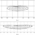
- the primary low-beam light pattern is the central region of the low-beam light pattern with high illuminance
- the auxiliary low-beam light pattern is the widened region of the low-beam light pattern, thus ensuring that the left and right illumination range of the low-beam light pattern meets the requirements.
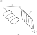
- a light-emitting module 100 which includes multiple light sources 101 and multiple optical units 110.
- the light sources 101 are located on the light incident side of the optical units 110, thus facilitating the optical units 110 in modulating the light emitted from the light sources 101.
- multiple optical units 110 are arranged in the transverse direction, and as shown in FIG. 2 , multiple optical units 110 are arranged in the vertical direction.
- each optical unit 110 includes a reflection part 120 and a lens unit.
- the light source 101 corresponds to the reflection part 120, and the lens unit is located on the light-emitting side of the reflection part 120.
- the focuses of the lens units are arranged on the reflection surface of the reflection part 120 or near the reflection surface to ensure clear imaging. Accordingly, after the light source 101 emits light, the light is reflected by the reflection surface of the reflection part 120, enters the lens unit, and is modulated by the lens unit before finally being emitted to form a light pattern unit.
- multiple optical units 110 of the light-emitting module 100 can form multiple light pattern units, and the combination of multiple light pattern units forms the light-emitting pattern of the light-emitting module 100.
- the light-emitting module 100 includes four optical units 110 arranged in the transverse direction (in the x direction). Each optical unit 110 is provided with a reflection part 120 and a lens unit. Each optical unit 110, in cooperation with the light source 101, can emit light to form a light pattern unit. Ultimately, the four light pattern units combine in the transverse direction to form the light-emitting pattern of the light-emitting module 100.
- the light-emitting module 100 includes two optical units 110 arranged in the vertical direction (in the z direction). Each optical unit 110 is provided with a reflection part 120 and a lens unit. Each optical unit 110, in cooperation with the light source 101, can emit light to form a light pattern unit. Ultimately, the two light pattern units combine to form the light-emitting pattern of the light-emitting module 100.
- the light-emitting module 100 is modularized (with multiple light sources 101 and multiple optical units 110), making the optical units 110 within the light-emitting module 100 relatively independent, allowing for more flexible modulation of individual light patterns. Therefore, when the light-emitting pattern is locally adjusted, only part of the optical units 110 can be adjusted, and the remaining optical units 110 can be avoided from being adjusted. Compared to directly using a single large lens within the light-emitting module 100, the present invention helps shorten the development cycle, enables more refined adjustments of the light pattern, and improves the accuracy of achieving the desired light pattern.
- the focus of the lens unit is located on the reflection surface of the reflection part 120 or near the reflection surface, including but not limited to when the focus is located at the boundary of the reflection surface, near the boundary, or at a non-boundary location.
- the light-emitting module 100 can be applied in the low-beam lighting apparatus.
- the focus is located on the reflection surface or near the reflection surface (excluding the boundary of the reflection surface or positions near the boundary), the light-emitting module 100 can be used in high-beam lighting apparatus.
- the lens unit includes a lens 130, which can firstly facilitate the miniaturization of the lens unit, and at the same time, can also avoid excessive light refraction to the outside, thereby reducing light loss.
- a cross-section of a light incident surface of the lens 130 (along an x direction) and a longitudinal section of a light-emitting surface of the lens 130 (along a z direction) are both curves. Therefore, after light is incident on the lens 130 via a reflection surface, the light incident surface and the light-emitting surface of the lens 130 can achieve bidirectional collimation, thereby obtaining a better light pattern effect in a light-emitting direction (along a y direction).
- the lens unit when the lens unit includes a lens 130, one of the cross-section and the longitudinal section of the light incident surface of the lens 130 is a curve, and the other is a straight line. Therefore, after light is incident on the lens 130 via the reflection surface, the light incident surface of the lens 130 can achieve unidirectional collimation, and a collimation direction can be transverse or longitudinal. It is also not precluded that, in another embodiment, the cross-section and the longitudinal section of the light incident surface of the lens are both curves.
- the lenses 130 of two adjacent lens units can be spliced to form a module lens 141.
- the lenses 130 that are arranged in the transverse direction are sequentially spliced in the transverse direction to form the module lens 141.
- the lenses 130 that are arranged in the vertical direction are sequentially spliced in the vertical direction to form the module lens 141.
- the lens unit can also include multiple lenses, thereby enabling light to be modulated multiple times, which facilitates obtaining a better light pattern.
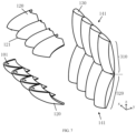
- optical units 110 are arranged in the transverse direction (along the x direction), and the lens unit can also include an inner lens 150 and an outer lens 160, wherein the outer lens 160 is arranged on a light-emitting side of a reflection part 120, and the inner lens 150 is located between the reflection part 120 and the outer lens 160. Therefore, after the light is reflected by the reflection part 120, the light is first incident on the inner lens 150, and then the light is emitted from the inner lens 150 to the outer lens 160 and is finally emitted to form a light pattern unit.
- the lens unit when the optical units 110 are arranged in a vertical direction (along the z direction), the lens unit can still include the inner lens 150 and the outer lens 160.
- the arrangement thereof differs from the embodiment in which the optical units are transversely arranged only in the arrangement direction. Therefore, the arrangement can be referred to and understood without further elaboration.
- a low-beam light pattern of a low-beam lighting apparatus By superimposing the primary low-beam light pattern shown in FIG. 5 and the auxiliary low-beam light pattern shown in FIG. 6 , a low-beam light pattern of a low-beam lighting apparatus can be obtained.
- the primary low-beam light pattern can improve the central brightness of the low-beam light pattern, and the auxiliary low-beam light pattern can enable the low-beam light pattern to be widened more effectively.
- the high and low beam integrated lighting apparatus includes two above-mentioned light-emitting modules 100.
- One light-emitting module 100 is a low-beam light-emitting module 310 capable of forming a low-beam light pattern
- the other light-emitting module 100 is a high-beam light-emitting module 320 capable of forming a high-beam light pattern.
- the high and low beam integrated lighting apparatus is divided into the low-beam light-emitting module 310 and the high-beam light-emitting module 320 with a dashed line as the boundary.
- the high-beam light-emitting module 320 includes multiple light sources 101 and multiple optical units 110.
- the multiple optical units 110 include a reflection part 120 and a lens unit.
- the lens unit includes a bidirectionally collimated lens 130, and multiple lenses 130 are spliced to form a module lens 141.
- the light sources 101 are emitted along the y direction through multiple optical units 110 to form multiple light pattern units.
- the multiple light pattern units are combined to form a high-beam light pattern.
- the multiple inner lenses 150 are spliced to form a module inner lens 142, and the multiple outer lenses 160 are spliced to form a module outer lens 143.
- the light sources 101 are emitted along the y direction through multiple optical units 110 to form multiple light pattern units.
- the multiple light pattern units are combined to form a low-beam light pattern having a light-dark cut-off line.
- the high-beam light-emitting module 320 includes multiple light sources 101 and multiple optical units 110.
- the multiple optical units 110 include a reflection part 120 and a lens unit.
- the lens unit includes a lens 130 that is bidirectionally collimated in both the x-direction and the z-direction, and multiple lenses 130 are spliced to form a module lens 141.
- the light sources 101 are emitted along the y direction through multiple optical units 110 to form multiple light pattern units.
- the multiple light pattern units are combined to form a high-beam light pattern.
- the low-beam light-emitting module 310 and the high-beam light-emitting module 320 are arranged in a vertical direction (i.e., z-direction).
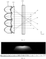
- the low-beam inner lens 181 and the high-beam inner lens 191 are arranged front-to-rear along the front-rear direction (along the y-direction).
- the low-beam inner lens 181 is arranged at the rear, and the high-beam inner lens 191 is arranged at the front.
- the arrangement can be determined based on the focal lengths of each. It should be understood that as the focal length increases, brightness increases, but the size of the light pattern decreases. Therefore, the focal length can be set reasonably according to the light pattern and customer requirements.
- the low-beam inner lens 181 and the high-beam inner lens 191 are arranged along the vertical direction (along the z-direction) and integrally molded, that is, the low-beam inner lens 181 and the high-beam inner lens 191 are spliced along the vertical direction.
- a heat sink 330 can be arranged between the light sources 101 of two adjacent light-emitting modules 100. By utilizing the opposite sides of the heat sink 330, the light sources 101 of the two light-emitting modules 100 can be separately cooled. This can fully utilize the space between the light sources 101 of the two light-emitting modules 100, thereby reducing the volume.
- a heat sink 330 can be arranged between the light sources 101 of the low-beam light-emitting module 310 and the high-beam light-emitting module 320. By utilizing the opposite sides of the heat sink 330, the light sources 101 of the two light-emitting modules 100 can be separately cooled.
- a corresponding heat sink 330 can be provided for the light source 101 of each light-emitting module 100.
- a heat sink 330 can be arranged on the side of the low-beam light-emitting module 310 that is away from the high-beam light-emitting module 320 to dissipate heat from the light source 101 of the low-beam light-emitting module 310.
- a heat sink 330 can be arranged on the side of the high-beam light-emitting module 320 that is away from the low-beam light-emitting module 310 to dissipate heat from the light source 101 of the high-beam light-emitting module 320.
- the low-beam light-emitting module 310 includes four light sources 101 and four optical units 110.
- the four optical units 110 are schematically represented by the four dashed-line boxes shown in FIG. 12 and are sequentially arranged along the x-direction as a first unit 111, a second unit 112, a third unit 113, and a fourth unit 114.
- the light-emitting direction is the y-direction.
- the first unit 111 and the second unit 112 are two units close to the edge, respectively, and the third unit 113 and the fourth unit 114 are two units close to the middle, respectively.
- the inner lenses 150 of different optical units 110 in the low-beam light-emitting module 310 can be arranged differently.
- the curvature of the cross-section of the light incident surface of the inner lenses 150 of the first unit 111 and the second unit 112, which are near the edges is greater than the curvature of the cross-section of the light incident surface of the inner lenses 150 of the third unit 113 and the fourth unit 114, which are near the center. Accordingly, as shown in FIG.
- the light incident through the light incident surfaces with larger cross-sectional curvatures on both sides of the low-beam inner lens 181 will cross each other in the transverse direction (x direction), i.e., the horizontal direction, due to the large-angle refraction.
- the module outer lens 143 is arranged at a point in the optical path during the crossing process, it is possible to allow the light to pass through without requiring a wide module outer lens 143. Thus, the left and right openings of the lens can be further reduced.
- the surface shape 1431 formed by connecting the light-emitting surfaces of outer lenses of adjacent light-emitting modules can be a curved surface that is convex or concave, thereby improving the continuity of appearance.
- the surface shape 1431 formed by connecting the light-emitting surfaces of the outer lenses of adjacent light-emitting modules can also be changed accordingly.
- the surface shape 1431 formed by connecting the light-emitting surfaces of the outer lenses of adjacent light-emitting modules can be a flat surface.
- the high and low beam integrated lighting apparatus includes a reflecting assembly 450 that fixes the reflection part 120, a low-beam circuit board 440 that integrates the light source 101 of the low-beam light-emitting module 310, a high-beam circuit board 430 that integrates the light source 101 of the high-beam light-emitting module 320, an inner lens assembly 420 provided with the low-beam inner lens 181 and the high-beam inner lens 191, a lens bracket 410, and an integral connection of the low-beam outer lens 182 and the high-beam outer lens 192, which are assembled along the direction of the light path.
- vehicle lamp which includes the above-described low-beam lighting apparatus, the above-described high-beam lighting apparatus, or the above-described high and low beam integrated lighting apparatus.
- vehicle lamp of the present invention can be applied to transportation vehicles such as bicycles, motorcycles, automobiles, ships, and aircraft, without limitation in the present invention.
- the present invention provides a high and low beam integrated lighting apparatus and a vehicle lamp, in which the low-beam light-emitting module and the high-beam light-emitting module are provided with optical units to achieve modularization. Therefore, this makes each light-emitting module relatively independent, and their light pattern modulation is more flexible without interfering with each other, which can shorten the research and development cycle.
- the vehicle lamp of the present invention can be applied to transportation vehicles such as bicycles, motorcycles, automobiles, ships, and aircraft.
Landscapes
- Engineering & Computer Science (AREA)
- General Engineering & Computer Science (AREA)
- Physics & Mathematics (AREA)
- Microelectronics & Electronic Packaging (AREA)
- Optics & Photonics (AREA)
- Non-Portable Lighting Devices Or Systems Thereof (AREA)
Applications Claiming Priority (2)
| Application Number | Priority Date | Filing Date | Title |
|---|---|---|---|
| CN202211551897.8A CN115875629A (zh) | 2022-12-05 | 2022-12-05 | 一种远近光一体照明装置和车灯 |
| PCT/CN2023/117699 WO2024119931A1 (fr) | 2022-12-05 | 2023-09-08 | Appareil d'éclairage intégré à feux de route et de croisement, et phare de véhicule |
Publications (2)
| Publication Number | Publication Date |
|---|---|
| EP4582737A1 true EP4582737A1 (fr) | 2025-07-09 |
| EP4582737A4 EP4582737A4 (fr) | 2025-09-03 |
Family
ID=85765947
Family Applications (1)
| Application Number | Title | Priority Date | Filing Date |
|---|---|---|---|
| EP23899514.6A Pending EP4582737A4 (fr) | 2022-12-05 | 2023-09-08 | Appareil d'éclairage intégré à feux de route et de croisement, et phare de véhicule |
Country Status (3)
| Country | Link |
|---|---|
| EP (1) | EP4582737A4 (fr) |
| CN (3) | CN120444573A (fr) |
| WO (1) | WO2024119931A1 (fr) |
Families Citing this family (7)
| Publication number | Priority date | Publication date | Assignee | Title |
|---|---|---|---|---|
| CN120444573A (zh) * | 2022-12-05 | 2025-08-08 | 华域视觉科技(上海)有限公司 | 一种近光出光模组及远近光照明装置和车灯 |
| CN116557805B (zh) * | 2023-04-21 | 2026-04-14 | 马瑞利汽车零部件(芜湖)有限公司 | 基础近光成像透镜及光学系统 |
| CN116480970A (zh) * | 2023-05-15 | 2023-07-25 | 南宁燎旺车灯股份有限公司 | 光学模组和车灯 |
| CN120457299A (zh) * | 2023-06-02 | 2025-08-08 | 华域视觉科技(上海)有限公司 | 一种车灯照明装置、车灯及汽车 |
| TWI904471B (zh) * | 2023-09-07 | 2025-11-11 | 堤維西交通工業股份有限公司 | 多功能的車燈裝置 |
| CN119244962B (zh) * | 2024-12-04 | 2025-06-10 | 浙江豪钿科技有限公司 | 一种近光增亮且光斑均匀的电动车用led大灯模组 |
| CN119879118B (zh) * | 2025-03-28 | 2025-07-08 | 华域视觉科技(常熟)有限公司 | 车灯模组及车灯 |
Family Cites Families (18)
| Publication number | Priority date | Publication date | Assignee | Title |
|---|---|---|---|---|
| TWI363191B (en) * | 2007-12-31 | 2012-05-01 | Aixin Technologies Llc | Lens array and illumination module |
| DE102009049458A1 (de) * | 2009-10-15 | 2011-04-28 | Hella Kgaa Hueck & Co. | Projektionsschweinwerfer für Fahrzeuge |
| JP2018092883A (ja) * | 2016-11-25 | 2018-06-14 | 株式会社小糸製作所 | 車両用灯具 |
| TWI607179B (zh) * | 2016-11-30 | 2017-12-01 | 隆達電子股份有限公司 | 透鏡陣列、使用透鏡陣列的車燈透鏡組及使用車燈透鏡組的車燈總成 |
| KR20190081690A (ko) * | 2017-12-29 | 2019-07-09 | 에스엘 주식회사 | 차량용 램프 |
| FR3084728B1 (fr) * | 2018-07-31 | 2021-03-19 | Valeo Vision | Module lumineux imageant la surface eclairee d'un collecteur |
| US11092304B2 (en) * | 2018-09-05 | 2021-08-17 | Flex-N-Gate Advanced Product Development, Llc | Vehicle adaptable driving beam headlamp |
| FR3093789B1 (fr) * | 2019-03-14 | 2022-05-27 | Valeo Vision | Dispositif lumineux imageant les surfaces eclairees d’au moins deux collecteurs |
| CN110736072A (zh) * | 2019-11-01 | 2020-01-31 | 华域视觉科技(上海)有限公司 | 前照灯照明模组及车辆 |
| CN113958921A (zh) * | 2020-12-29 | 2022-01-21 | 华域视觉科技(上海)有限公司 | 照明模组、照明装置及车辆 |
| FR3118122B1 (fr) * | 2020-12-18 | 2023-02-24 | Valeo Vision | Module lumineux d’un dispositif d’éclairage de véhicule automobile |
| FR3118124B1 (fr) * | 2020-12-18 | 2022-12-30 | Valeo Vision | Module d’éclairage automobile bi-fonction avec eclairage de la lentille d’un module d’eclairage inactif |
| TWI788114B (zh) * | 2021-02-09 | 2022-12-21 | 誠益光電科技股份有限公司 | 車燈裝置 |
| TWI793524B (zh) * | 2021-02-09 | 2023-02-21 | 誠益光電科技股份有限公司 | 車燈裝置 |
| TWM611948U (zh) * | 2021-02-09 | 2021-05-11 | 誠益光電科技股份有限公司 | 車燈裝置 |
| CN214700545U (zh) * | 2021-02-23 | 2021-11-12 | 华域视觉科技(上海)有限公司 | 一种远近光一体模组、车灯及车辆 |
| CN218626579U (zh) * | 2022-12-05 | 2023-03-14 | 华域视觉科技(上海)有限公司 | 出光模组及近光、远光和远近光一体照明装置、车灯 |
| CN120444573A (zh) * | 2022-12-05 | 2025-08-08 | 华域视觉科技(上海)有限公司 | 一种近光出光模组及远近光照明装置和车灯 |
-
2022
- 2022-12-05 CN CN202510893243.0A patent/CN120444573A/zh active Pending
- 2022-12-05 CN CN202211551897.8A patent/CN115875629A/zh active Pending
-
2023
- 2023-09-08 WO PCT/CN2023/117699 patent/WO2024119931A1/fr not_active Ceased
- 2023-09-08 CN CN202390000204.8U patent/CN221897683U/zh active Active
- 2023-09-08 EP EP23899514.6A patent/EP4582737A4/fr active Pending
Also Published As
| Publication number | Publication date |
|---|---|
| CN120444573A (zh) | 2025-08-08 |
| WO2024119931A1 (fr) | 2024-06-13 |
| EP4582737A4 (fr) | 2025-09-03 |
| CN221897683U (zh) | 2024-10-25 |
| CN115875629A (zh) | 2023-03-31 |
Similar Documents
| Publication | Publication Date | Title |
|---|---|---|
| EP4582737A1 (fr) | Appareil d'éclairage intégré à feux de route et de croisement, et phare de véhicule | |
| KR102410899B1 (ko) | 자동차 헤드램프용 광 모듈 | |
| JP7073582B2 (ja) | 照明モジュール、車両用ランプおよび車両 | |
| JP5406566B2 (ja) | 車両用前照灯 | |
| CN103322487B (zh) | 车辆用前照灯 | |
| CN210740277U (zh) | 远近光一体前照灯模组、前照灯及车辆 | |
| US20220349542A1 (en) | Vehicle light optical element assembly, vehicle lighting device, vehicle light and vehicle | |
| JP2018098105A (ja) | 車両用前照灯 | |
| JP2018098011A (ja) | 車両用前照灯 | |
| CN116105090A (zh) | 出光模组及近光、远光、远近光一体照明装置、车灯 | |
| WO2024114496A1 (fr) | Dispositif d'éclairage et véhicule automobile | |
| JP2018116869A (ja) | 灯具 | |
| CN218626579U (zh) | 出光模组及近光、远光和远近光一体照明装置、车灯 | |
| CN216644082U (zh) | 光学系统、车灯模组、车灯和车辆 | |
| EP4585853A1 (fr) | Dispositif d'éclairage et lampe de véhicule | |
| EP4137742A1 (fr) | Système optique de lampe de véhicule, module de lampe de véhicule, et véhicule | |
| CN219510649U (zh) | 一种照明装置和车灯 | |
| EP4206524B1 (fr) | Système de réflexion optique pour dispositif d'éclairage de lampe de véhicule, et dispositif d'éclairage de lampe de véhicule | |
| JP2021197252A (ja) | 車両用灯具 | |
| CN116146930A (zh) | 光学透镜模组及车灯 | |
| JP6471457B2 (ja) | 車両用灯具 | |
| CN224135709U (zh) | 用于前大灯的光学系统 | |
| CN111780049A (zh) | 一种车辆反射镜及基于此的近光单元 | |
| EP4660522A1 (fr) | Module d'éclairage de phare de véhicule et phare de véhicule | |
| WO2023019568A1 (fr) | Module d'éclairage de phare de véhicule et phare de véhicule |
Legal Events
| Date | Code | Title | Description |
|---|---|---|---|
| STAA | Information on the status of an ep patent application or granted ep patent |
Free format text: STATUS: THE INTERNATIONAL PUBLICATION HAS BEEN MADE |
|
| PUAI | Public reference made under article 153(3) epc to a published international application that has entered the european phase |
Free format text: ORIGINAL CODE: 0009012 |
|
| STAA | Information on the status of an ep patent application or granted ep patent |
Free format text: STATUS: REQUEST FOR EXAMINATION WAS MADE |
|
| 17P | Request for examination filed |
Effective date: 20250402 |
|
| AK | Designated contracting states |
Kind code of ref document: A1 Designated state(s): AL AT BE BG CH CY CZ DE DK EE ES FI FR GB GR HR HU IE IS IT LI LT LU LV MC ME MK MT NL NO PL PT RO RS SE SI SK SM TR |
|
| STAA | Information on the status of an ep patent application or granted ep patent |
Free format text: STATUS: EXAMINATION IS IN PROGRESS |
|
| A4 | Supplementary search report drawn up and despatched |
Effective date: 20250806 |
|
| RIC1 | Information provided on ipc code assigned before grant |
Ipc: F21S 41/265 20180101AFI20250731BHEP Ipc: F21S 41/32 20180101ALI20250731BHEP Ipc: F21V 13/04 20060101ALI20250731BHEP Ipc: F21W 107/10 20180101ALI20250731BHEP Ipc: F21W 102/13 20180101ALI20250731BHEP Ipc: F21S 41/148 20180101ALI20250731BHEP Ipc: F21S 41/26 20180101ALI20250731BHEP Ipc: F21S 41/36 20180101ALI20250731BHEP |
|
| 17Q | First examination report despatched |
Effective date: 20250819 |
|
| DAV | Request for validation of the european patent (deleted) | ||
| DAX | Request for extension of the european patent (deleted) |