【0001】
【発明の属する技術分野】
本発明は、微生物の働きにより食品残渣その他の有機系廃棄物で成る生ゴミをコンポスト化するための技術に係わり、特に生ゴミに含まれる油分や塩分の多くを除去して微生物による生ゴミの発酵分解が促進されるようにした生ゴミ処理機に関する。
【0002】
【従来の技術】
近年、産業の発展に伴って多くの廃棄物が発生して深刻な社会問題となっている。特に、食品残渣などの生ゴミは悪臭を放つ上、多量の水分を含んでいることから、その処理に苦慮してきた。そこで、生ゴミをコンポスト化する種々の装置が提案されている。これには、生ゴミを単に加熱乾燥して減容する方式もあるが、その多くは微生物の働きを利用して生ゴミを発酵分解するものである。
【0003】
ここに、微生物による発酵分解には、空気を遮断した下での嫌気性分解と、酸素存在下での好気性分解とがある。前者は、嫌気性微生物により発酵分解が緩やかに進行し、いわゆる腐敗現象を呈して悪臭を発するが、後者は好気的条件が適切に維持されると発酵分解が急速に進行し、比較的短期間で反応が終了し、悪臭の発生も少ない。特に、後者の好気性分解では、処理中に多量の発酵熱が放出されて温度上昇を伴うために生ゴミを衛生的に処理でき、しかも温度上昇が好気性微生物の自己増殖を促するために生ゴミの発酵分解を加速度的に高めることができる。
【0004】
ところが、生ゴミの発酵分解が進行する過程では多量の水分が発生し、その水分量が70%を越えると、生ゴミ中への酸素供給が妨げられ、好気性分解の障害となる。このため、従来装置では、生ゴミを撹拌する発酵槽内に籾殻やおが屑といった水分調整剤を添加するか、若しくは温風を送り込むなどして生ゴミの含水率を低下させることが行われている。
【0005】
【発明が解決しようとする課題】
然し乍ら、水分調整剤を添加するものでは過剰なコンポストが生成されてしまうのみならず、生ゴミ自体の処理能力が大きく低下してしまうという欠点を有する。一方、温風を送り込むものでは、水分調整剤の添加量を大幅に削減するか、又はこれを一切添加せずして大量の生ゴミを処理することができるものの、食品残渣として生ずる生ゴミは油分や塩分を含み、これによって生ゴミを発酵分解する微生物が死滅したり、又はその増殖や活動が阻害される結果、生ゴミの発酵分解が良好に進行しないという難点があった。特に、多量の油分を含んだ生ゴミでは、生ゴミの粒子が油膜で覆われたり、生ゴミの分解液上に油膜が形成され、これによって生ゴミ中への酸素供給、及び水分の蒸発が妨げられるために、生ゴミの発酵分解が大きく低下するという問題があった。
【0006】
本発明は以上のような事情に鑑みて成されたものであり、その目的は油分などを含んだ生ゴミでも効率よく発酵分解してコンポスト化することのできる生ゴミ処理機を提供することにある。
【0007】
【課題を解決するための手段】
本発明は上記目的を達成するため、発酵槽に供給する生ゴミから油分などの発酵阻害物質を除去するための分離装置を備えた生ゴミ処理機であって、前記分離装置は生ゴミの受口及び吐出口を形成する外胴と、この外胴内に設けられる円筒状のスクリーンバスケットと、このスクリーンバスケット内に通される回転軸と、この回転軸に所定の間隔で固定されるロータベーンとを有し、前記スクリーンバスケットにはその周方向に沿って複数条の水切スリットが形成され、その各水切スリットにロータベーンの先端部が差し込まれると共に、前記外胴には水切スリットを通過した廃液を外部に排出するための排液口が穿設されて成ることを特徴とする。
【0008】
特に、本発明はより好適な態様として、隔壁により内部が複数の処理室に仕切られる発酵槽と、その一端側の処理室から他端側の処理室へ生ゴミを送るための移送路と、前記発酵槽に供給する生ゴミから油分などの発酵阻害物質を除去するための分離装置と、この分離装置内の生ゴミに浴びせるための温水が蓄えられる湯槽とを備えた生ゴミ処理機であって、前記移送路にはその内部に加熱空気を吹き込むための温風供給管が接続されると共に、前記分離装置は生ゴミの受口及び吐出口を形成する外胴と、この外胴内に設けられる円筒状のスクリーンバスケットと、このスクリーンバスケット内に通される回転軸と、この回転軸に所定の間隔で固定されるロータベーンとを有し、前記スクリーンバスケットにはその周方向に沿って複数条の水切スリットが形成され、その各水切スリットにロータベーンの先端部が差し込まれ、前記外胴には水切スリットを通過した廃液を外部に排出するための排液口が穿設されて成ることを特徴とする生ゴミ処理機を提供するものである。
【0009】
尚、上記の発酵阻害物質とは、生ゴミのコンポスト化に悪影響を及ぼすものであり、これには生ゴミを分解する微生物を死滅させたり、その増殖や活動を阻害する油分ほか、塩分などが含まれる。
【0010】
【発明の実施の形態】
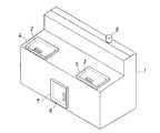
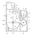
以下、本発明の適用例を図面に基づいて詳細に説明する。先ず、図1に本発明の好適な一例として係る生ゴミ処理機の斜視外観図を示す。1は処理機本体であり、その前部上面には生ゴミ投入口2と内部点検口3が設けられ、それら開口部は扉4,5により開閉自在とされている。又、処理機本体1の下部前面にはコンポスト化した生ゴミの取出口6と此れを開閉する扉7が設けられ、後部最上位には排気筒8が突出せしめられる。
【0011】
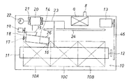
図2は、同生ゴミ処理機の内部構造を示した正面概略図である。図2において、9は上記の排気筒が接続する脱臭装置、10は直列に並んだ三つの処理室10A〜10Cから成る発酵槽であり、その近隣には一端側の処理室10A(一次発酵室)から他端側の処理室10B(二次発酵室)へ生ゴミを送るための移送路11が並設される。移送路11は円筒形のトラフとして、その内部にロータ軸12をもつフィーダを構成し、そのロータ軸12はモータ13の伝達動力を得て所定方向に回転駆動するようになっている。
【0012】
又、フィーダのトラフを成す移送路11上には、発酵槽10の一端側に分離装置14が所定の角度を有して傾斜状に設けられる。この分離装置14は、発酵槽10に供給する生ゴミから予め油分や塩分といった発酵阻害物質を除去するためのものであり、その一端上部はホッパ15を介して上記の生ゴミ投入口2に連通され、他端(下流側)下部には油分などを含んだ廃液を外部に排出するための排液口16が穿設されている。尚、分離装置14は回転軸17を内蔵し、その一端にチェーン18を介して駆動源19の動力が伝達されるようにしてある。特に、この分離装置14は後述のように破砕機能と脱水機能を兼備し、その内部に投入された生ゴミを所定の大きさに破砕しながら温水で洗浄し、生ゴミに含まれる油分や塩分を温水中に溶出せしめ、それら発酵阻害物質の多くが除去された湯洗い後の生ゴミを処理室10A内に吐出し、使用済みの温水を廃液として排液口16から図示せぬ管路を通じて外部に排出する。
【0013】
20は分離装置内に供給すべき温水を蓄える湯槽(温水タンク)、21はその加熱源を成すヒータであり、このヒータ21は空気加熱器を兼用して一端にファン22をもつ温風供給管23に介在される。温風供給管23の他端側は二系統に分岐され、その一方が移送路11に接続されると共に、他方は発酵槽10上に配置される多孔状のノズル管24に接続される。よって、ファン22による送風はヒータ21により加熱されて移送路11とノズル管24の内部に供給され、ノズル管24内に供給された加熱空気は発酵槽10内に向けて放出される。尚、ヒータ21を湯槽20の加熱源として併用せず、これを湯槽用と空気加熱用とに分けて設けても良い。
【0014】
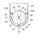
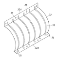
次に、図3は分離装置を部分的に破断して示した内部側面図であり、図4〜図6には図3におけるA−A、B−B、及びC−C断面を示す。これらの図で明らかなように、分離装置14は半円弧状の底面をもつ上部開口した溝形の外胴25を備える。この外胴25は、その上部開口部分のうち上流側の一端がホッパ15を介して図1に示した生ゴミ投入口2と連通する受口25Aとされ、外胴25の下流側の一端下部には吐出口25Bが形成される。又、外胴25内には円筒状のスクリーンバスケット26と、このスクリーンバスケット内に生ゴミを導入するための開口部27Aをもつ仕切板27とが設けられる。更に、外胴25にはその一端から他端に亙ってスクリーンバスケット26の中心を通る上記の回転軸17が貫通され、その外周には役割が異なる三種類のロータベーン28,29,30が所定の間隔で180度ずつ取付角度をずらして交互に固定される。このうち、上流のロータベーン28は受口25Aから外胴25内に供給された生ゴミを破砕する回転刃として図4のような鋸状の刃部28Aを形成し、その相互間には外胴内を横断する固定刃31が設けられる。
【0015】
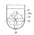
一方、中流と下流のロータベーン29,30は生ゴミの送り用として所定の捩れを有すると共に、下流のロータベーン30はスクレーパ機能を兼備するものとしてスクリーンバスケット26内に配列される。このスクリーンバスケット26は、両端に鍔部32Aをもつ図7のような弧状スクリーン32を三つ円筒状に組み合わせて成り、その外周には周方向に沿う環状の水切スリット33が所定の間隔で形成される。その各水切スリット33は、スクリーンバスケット26内に配されるロータベーン30に対応し、そのロータベーン30の各先端部が水切スリット33に差し込まれるようにしてある。34は水切スリットに差し込むべくロータベーンの先端部に形成した突片であり、この突片34はロータベーン30の回転駆動により水切スリット33内を摺動して生ゴミの目詰まりを防止する働きをする。尚、スクリーンバスケット26を構成する弧状スクリーン32は、水切スリット33の間で鍔部32Aに取付用の孔35を有し、その孔35の位置で外胴25の内壁に設けたブラケット36に固定される。
【0016】
そして、以上のような分離装置14によれば、受口25Aから外胴25内に投入された生ゴミをロータベーン28と固定刃31とで破砕しつつ、これを湯槽20から外胴25内に供給される温水とを混合し、その混合物をロータベーン29により仕切板の開口部27Aを通してスクリーンバスケット26内に送り込み、スクリーンバスケット26内では油分や塩分などが溶出された温水を廃液として水切スリット33から排液口16を通じて外部排出し、水切スリット33を透過せずに残った高湿固形分を吐出口25Bより発酵槽10に供給する。
【0017】
次に、図8は生ゴミ処理機の内部側面図、図9はその内部平面図を示す。図8から明らかなように、分離装置14には上記の吐出口25Bから発酵槽の一次処理室10Aの上部に延びる生ゴミ供給用のシュート37が接続され、分離装置の外胴25には湯槽20より延びる給湯管38が接続される。一方、発酵槽10の底部には加熱室39が形成され、その加熱室39内に図示せぬ送風機からヒータ40を通じて加熱空気が供給される構成としてある。
【0018】
又、図8及び図9から明らかなように、移送路11の両端は発酵槽の処理室10A,10Bと連通路41A,41Bで接続され、移送路11内に通されるロータ軸12の一端にはスプロケット42が取り付けられる。更に、発酵槽10内にも移送路11に平行するロータ軸43が通され、その一端には大小二つのスプロケット44,45が取り付けられる。そして、大径のスプロケット44が図2に示したモータ13とチェーン46で連結されると共に、両ロータ軸のスプロケット42,45にチェーン47が掛け回されることにより、ロータ軸12,43が同調して回転駆動するようにしてある。ここで、ロータ軸43には処理室10A〜10C内の生ゴミを撹拌する棒状の撹拌羽根48が所定の間隔で取り付けられ、処理室を区分する隔壁49,50には生ゴミを通過を許容する開口部49A,50Aが形成される。よって、分離装置14の吐出口25Bより排出された生ゴミはシュート37を通じて一次処理室10Aに供給され、この処理室10Aで撹拌されつつ連通路41Aから移送路11の一端部に導入された後、移送路11内を通じてその他端連通路41Bより二次処理室10Bに送られる。更に、二次処理室10Bに送られた生ゴミは、開口部49Aより通って中央の処理室10C(熟成室)に送られ、その一部は微生物の増殖用として開口部50Aから一次処理室10Aに還元される。
【0019】
尚、中央の処理室10Cには移送路11の下方に延びる排出路51が接続され、処理室10C内に送り込まれた生ゴミの大部分はコンポスト化した状態で排出路51から外部に排出される。図8において、52は排出路より排出された生ゴミのコンポストを収容する受箱であり、この受箱52は扉7の開放により移送路11の下方から処理機本体1外へ取り出し可能とされている。
【0020】
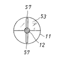
次に、図10は移送路の内部側面図であり、図11及び図12には図10におけるA−A、B−B断面を示す。これらの図で明らかなように、移送路11内には所定の間隔をおいて二つの上部仕切り53,54があり、その区間内で移送路11に温風供給管23の分岐端が接続され、出口(下流連通路41B)側の上部仕切り53には図12に示すよう扉板54がヒンジ結合されている。又、移送路11内を通るロータ軸12には、上部仕切り53より上流側で螺旋状の送り羽根56が取り付けられるほか、上部仕切り53,54の間で棒状の撹拌羽根57が取り付けられる。よって、移送路11の一端側に導入された生ゴミは、送り羽根56と撹拌羽根57とにより撹拌されつつ他端側へ送られ、その過程で温風供給管23より送り込まれる加熱空気により水分量が低下され、その発酵分解が促進される。そして、下流側に達した生ゴミは扉板55を押し上げて連通路41Bより二次発酵室10Bへと送り込まれる。
【0021】
ここで、以上のように構成される生ゴミ処理機の作用を説明する。先ず、使用に際して扉4を開け、生ゴミ投入口2に生ゴミを投入するのであり、これにより生ゴミがホッパ15を通じて分離装置14の受口25Aより外胴25内に導入する。一方、湯槽20からは給湯管38を通じて外胴25内に温水が供給され、この温水が外胴25内の生ゴミに浴びせられる。このため、生ゴミは温水で洗浄されつつロータベーン28と固定刃31とで細かく切り刻まれ、その破砕物がロータベーン29の推進力によって仕切板の開口部27Aからスクリーンバスケット26内へと送り込まれる。スクリーンバスケット26内では、ロータベーン30が水切スリット33に沿って回転しながら生ゴミを先方へ推し進め、その過程で油分や塩分が溶出した温水が水切スリット33よりスクリーンバスケット26外へ排出され、これが廃液として排液口16より外部排出される。
【0022】
一方、スクリーンバスケット26内に残った高湿固形分は、吐出口25Bよりシュート37を通じて発酵槽の一次処理室10Aへ供給される。その生ゴミは、ノズル管24より放出される加熱空気と加熱室39内に供給される加熱空気とで上下から加熱されつつ、撹拌羽根48にて撹拌され、これが撹拌羽根48の掻き上げ作用により順に連通路41Aを通じて移送路11の一端に導入される。
【0023】
移送路11内では、温風供給管23より導入される加熱空気によって生ゴミの発酵が促進されつつ、送り羽根56や撹拌羽根57により生ゴミの撹拌及び推進が行われ、移送路11の他端に達したものから順に下流の連通路41Bより二次処理室10Bへ送り込まれる。
【0024】
二次処理室10Bに供給された生ゴミは、撹拌羽根48により撹拌されつつ加熱され、順に隔壁の開口部49Aを通じて中央の処理室10Cに移る。この処理室10Cでも生ゴミの撹拌、加熱が行われ、その一部が開口部50Aより一次処理室10Aに還元されて微生物の増殖用に供される一方、その大部分はコンポスト化した状態で排出路51から受箱52に回収される。
【0025】
以上、本発明の好適な一例を説明したが、係る生ゴミ処理機は上記のような構成に限らず、発酵槽10を単槽としたり、三つ以上の処理室に区分された多槽構造としてもよい。一方、分離装置において、上記例ではスクリーンバスケットを外胴の下流側に内蔵したが、これを外胴の全長に亙って内蔵し、その内部に受口から生ゴミが直接的に供給されるようにしてもよい。又、スクリーンバスケットは三つの弧状スクリーンを円筒形に組み合わせることに限らず、これを一体構造物とすることもできる。
【0026】
【発明の効果】
以上の説明で明らかなように、本発明によれば発酵槽に供給する生ゴミを予め湯洗いし、生ゴミに含まれる油分や塩分を除去するようにしていることから、微生物の活動が阻害されず、水分の蒸発も促されるために、生ゴミを効率的に発酵分解せしめて良質なコンポストを得ることができる。
【0027】
又、湯洗いした生ゴミを濾過する円筒状のスクリーンバスケットが、その周方向に沿う複数条の水切スリットを有し、その各水切スリットにロータベーンの先端部が差し込まれることから、水切スリットに生ゴミが詰まった場合でも、これが直ぐさまロータベーンにより掻き出されて目詰まりが防止されるために、油分などを含んだ廃液を確実に排出することができる。
【0028】
更に、発酵槽の一端側の処理室から他端側の処理室へ生ゴミを送るための移送路を備え、その内部に加熱空気が供給されるようにしていることから、生ゴミの発酵分解を促して処理時間を大幅に短縮することができる。
【図面の簡単な説明】
【図1】本発明に係る生ゴミ処理機を示した斜視外観図
【図2】同処理機の内部構造を示した正面概略図
【図3】分離装置を示した内部側面図
【図4】図3におけるA−A断面図
【図5】図3におけるB−B断面図
【図6】図3におけるC−C断面図
【図7】スクリーンバスケットの構成部品を示した斜視図
【図8】本発明に係る生ゴミ処理機の内部構造を示した側面図
【図9】同処理機の内部平面図
【図10】移送路の内部構造を示した側面図
【図11】図10におけるA−A断面図
【図12】図10におけるB−B断面図
【符号の説明】
10 発酵槽
10A〜10C 処理室
11 移送路
14 分離装置
16 排液口
17 回転軸
20 湯槽
23 温風供給管
25 外胴
25A 受口
25B 吐出口
26 スクリーンバスケット
30 ロータベーン
33 水切スリット
34 突片
38 給湯管
49,50 隔壁[0001]
TECHNICAL FIELD OF THE INVENTION
The present invention relates to a technology for composting garbage composed of food residues and other organic wastes by the action of microorganisms, and in particular, removes a large amount of oil and salt contained in garbage to remove garbage produced by microorganisms. The present invention relates to a garbage disposal machine in which fermentation decomposition is promoted.
[0002]
[Prior art]
In recent years, with the development of industry, a large amount of waste has been generated and has become a serious social problem. In particular, garbage such as food residue has a bad smell and contains a large amount of water, so that it has been difficult to treat it. Therefore, various devices for composting garbage have been proposed. In this method, there is a method of simply heating and drying garbage to reduce the volume, but most of the methods use the action of microorganisms to ferment and decompose garbage.
[0003]
Here, the fermentation decomposition by microorganisms includes anaerobic decomposition in the absence of air and aerobic decomposition in the presence of oxygen. In the former, the fermentation degradation proceeds slowly due to anaerobic microorganisms, causing a so-called putrefaction phenomenon, which gives off odors.In the latter, when aerobic conditions are properly maintained, the fermentation degradation proceeds rapidly, and the The reaction is completed in a short time, and the generation of offensive odor is small. In particular, in the latter aerobic decomposition, a large amount of fermentation heat is released during the treatment and the temperature rises, so that garbage can be sanitarily treated, and the temperature rise promotes the self-proliferation of aerobic microorganisms. The fermentation decomposition of garbage can be accelerated.
[0004]
However, a large amount of water is generated in the course of the fermentation and decomposition of garbage, and when the amount of water exceeds 70%, the supply of oxygen to the garbage is hindered, which hinders aerobic decomposition. For this reason, in the conventional apparatus, the water content of the garbage is reduced by adding a water regulator such as rice husk or sawdust into a fermenter for stirring the garbage, or by feeding hot air. .
[0005]
[Problems to be solved by the invention]
However, the addition of the water conditioning agent not only results in the generation of excessive compost, but also has the disadvantage that the processing capacity of the garbage itself is greatly reduced. On the other hand, in the case of sending hot air, although the amount of the water conditioning agent to be added can be greatly reduced or a large amount of garbage can be treated without adding it at all, the garbage generated as food residue is As a result, the microorganisms containing oil and salt, which ferment and decompose garbage, are killed or their growth and activity are inhibited. As a result, fermentation and decomposition of garbage do not proceed well. In particular, in the case of garbage containing a large amount of oil, the garbage particles are covered with an oil film or an oil film is formed on the decomposition liquid of the garbage, whereby the supply of oxygen to the garbage and the evaporation of water are prevented. There is a problem that the fermentation decomposition of the garbage is greatly reduced due to the hindrance.
[0006]
The present invention has been made in view of the above-described circumstances, and an object of the present invention is to provide a garbage processing machine capable of efficiently fermenting and decomposing garbage containing oil and the like into compost. is there.
[0007]
[Means for Solving the Problems]
In order to achieve the above object, the present invention is a garbage disposal machine provided with a separation device for removing a fermentation inhibitor such as oil from garbage supplied to a fermenter, wherein the separation device receives garbage. An outer shell forming a mouth and a discharge port, a cylindrical screen basket provided in the outer shell, a rotating shaft passed through the screen basket, and a rotor vane fixed to the rotating shaft at predetermined intervals. A plurality of drainage slits are formed in the screen basket along the circumferential direction, and the tip of the rotor vane is inserted into each of the drainage slits, and the waste liquid that has passed through the drainage slit is inserted into the outer shell. A drain port for draining to the outside is provided.
[0008]
In particular, as a more preferred aspect of the present invention, a fermentation tank whose interior is partitioned into a plurality of processing chambers by partition walls, and a transfer path for sending garbage from the processing chamber on one end side to the processing chamber on the other end side, A garbage disposer provided with a separation device for removing a fermentation inhibitor such as oil from the garbage supplied to the fermentation tank, and a hot water tank for storing hot water for bathing the garbage in the separation device. A hot air supply pipe for blowing heated air into the transfer path is connected to the transfer path, and the separating device includes an outer body forming a food waste receiving port and a discharge port, and an outer body formed in the outer body. A cylindrical screen basket provided, a rotating shaft passed through the screen basket, and a rotor vane fixed to the rotating shaft at predetermined intervals, wherein the screen basket has a plurality of pieces arranged along its circumferential direction. Article water A slit is formed, a tip end of a rotor vane is inserted into each of the drain slits, and a drain port for discharging waste liquid passing through the drain slit to the outside is formed in the outer body. A garbage processing machine is provided.
[0009]
In addition, the fermentation inhibitor mentioned above has an adverse effect on composting of garbage, and this includes killing microorganisms that decompose garbage, inhibiting oil and salt that inhibit the growth and activity, and salt content. included.
[0010]
BEST MODE FOR CARRYING OUT THE INVENTION
Hereinafter, application examples of the present invention will be described in detail with reference to the drawings. First, FIG. 1 shows a perspective external view of a garbage disposer according to a preferred example of the present invention. Reference numeral 1 denotes a processing machine main body, and a garbage input port 2 and an internal inspection port 3 are provided on an upper surface of a front portion thereof, and the openings thereof can be opened and closed by doors 4 and 5. A composted garbage outlet 6 and a door 7 for opening and closing the garbage are provided on the lower front surface of the processing machine main body 1, and an exhaust pipe 8 is projected from the uppermost rear portion.
[0011]
FIG. 2 is a schematic front view showing the internal structure of the same-size garbage disposal machine. In FIG. 2, reference numeral 9 denotes a deodorizing device to which the exhaust pipe is connected, and 10 denotes a fermentation tank including three processing chambers 10A to 10C arranged in series. ), A transfer path 11 for sending garbage to the processing chamber 10B (secondary fermentation chamber) on the other end side is provided in parallel. The transfer path 11 is a cylindrical trough, which constitutes a feeder having a rotor shaft 12 therein, and the rotor shaft 12 is rotatably driven in a predetermined direction by receiving power transmitted by a motor 13.
[0012]
Further, on the transfer path 11 forming a trough of the feeder, a separating device 14 is provided at one end of the fermenter 10 in an inclined manner at a predetermined angle. This separation device 14 is for removing a fermentation inhibitor such as oil or salt from the garbage supplied to the fermenter 10 in advance, and one upper end thereof communicates with the garbage inlet 2 through a hopper 15. In addition, a drain port 16 for discharging waste liquid containing oil and the like to the outside is provided in the lower end of the other end (downstream side). The separating device 14 has a rotating shaft 17 built in, and the power of a driving source 19 is transmitted to one end of the separating shaft 14 via a chain 18. In particular, the separation device 14 has both a crushing function and a dehydration function as described later, and crushes the garbage charged therein into a predetermined size and cleans the garbage with warm water, and removes oil and salt contained in the garbage. Is discharged into warm water, the garbage after washing with hot water from which many of the fermentation inhibitors have been removed is discharged into the treatment chamber 10A, and the used warm water is discharged as waste liquid from the drain port 16 through a conduit (not shown). Discharge to the outside.
[0013]
Reference numeral 20 denotes a hot water tank (hot water tank) for storing hot water to be supplied into the separator, and 21 denotes a heater serving as a heating source thereof. The heater 21 also serves as an air heater and has a fan 22 at one end having a fan 22 at one end. 23. The other end of the hot air supply pipe 23 is branched into two systems, one of which is connected to the transfer path 11, and the other of which is connected to a porous nozzle pipe 24 arranged on the fermenter 10. Therefore, the air blown by the fan 22 is heated by the heater 21 and supplied to the inside of the transfer path 11 and the nozzle pipe 24, and the heated air supplied to the nozzle pipe 24 is discharged toward the fermenter 10. Note that the heater 21 may not be used as a heating source of the hot water tank 20, but may be provided separately for the hot water tank and for the air heating.
[0014]
Next, FIG. 3 is a partially cutaway internal side view of the separation device, and FIGS. 4 to 6 show cross sections AA, BB, and CC in FIG. As can be seen in these figures, the separating device 14 comprises a groove-shaped outer shell 25 with an open top with a semicircular bottom. The upper end of the outer shell 25 is formed as a receiving port 25A that communicates with the garbage input port 2 shown in FIG. Is formed with a discharge port 25B. Further, a cylindrical screen basket 26 and a partition plate 27 having an opening 27A for introducing garbage into the screen basket are provided in the outer shell 25. Further, the above-mentioned rotary shaft 17 which passes through the center of the screen basket 26 penetrates the outer shell 25 from one end to the other end thereof, and three types of rotor vanes 28, 29, 30 having different roles are provided on the outer circumference thereof. Are fixed alternately by shifting the mounting angle by 180 degrees at intervals of. Among them, the upstream rotor vane 28 forms a saw-like blade portion 28A as shown in FIG. 4 as a rotary blade for crushing garbage supplied into the outer shell 25 from the receiving port 25A. A fixed blade 31 traversing the inside is provided.
[0015]
On the other hand, the middle and downstream rotor vanes 29 and 30 have a predetermined twist for feeding garbage, and the downstream rotor vanes 30 are arranged in the screen basket 26 as having a scraper function. This screen basket 26 is formed by combining three arc-shaped screens 32 having flanges 32A at both ends as shown in FIG. 7 in a cylindrical shape, and has an annular drainage slit 33 formed along the circumferential direction at a predetermined interval on the outer periphery. Is done. Each of the drainage slits 33 corresponds to a rotor vane 30 disposed in the screen basket 26, and each end of the rotor vane 30 is inserted into the drainage slit 33. Numeral 34 denotes a projection formed at the tip of the rotor vane to be inserted into the drain slit, and this projection 34 slides in the drain slit 33 by the rotation of the rotor vane 30 to prevent clogging of garbage. . The arcuate screen 32 constituting the screen basket 26 has a mounting hole 35 in the flange 32A between the drainage slits 33, and is fixed to a bracket 36 provided on the inner wall of the outer shell 25 at the position of the hole 35. Is done.
[0016]
Then, according to the separation device 14 as described above, the garbage put into the outer shell 25 from the receiving port 25A is crushed by the rotor vanes 28 and the fixed blades 31 and is crushed from the hot water tank 20 into the outer shell 25. The supplied hot water is mixed with the supplied hot water, and the mixture is fed into the screen basket 26 through the opening 27A of the partition plate by the rotor vanes 29. In the screen basket 26, the hot water in which oil, salt, and the like are eluted from the drain slit 33 as waste liquid. The high-humidity solids which are discharged outside through the drainage port 16 and do not pass through the draining slit 33 are supplied to the fermenter 10 from the discharge port 25B.
[0017]
Next, FIG. 8 is an internal side view of the garbage disposal machine, and FIG. 9 is an internal plan view thereof. As is clear from FIG. 8, a garbage supply chute 37 extending from the discharge port 25B to the upper part of the primary processing chamber 10A of the fermenter is connected to the separator 14, and a hot water tank is connected to the outer body 25 of the separator. A hot water supply pipe 38 extending from 20 is connected. On the other hand, a heating chamber 39 is formed at the bottom of the fermenter 10, and heating air is supplied from a blower (not shown) through the heater 40 into the heating chamber 39.
[0018]
8 and 9, both ends of the transfer path 11 are connected to the processing chambers 10A and 10B of the fermenter via communication paths 41A and 41B, and one end of the rotor shaft 12 passed through the transfer path 11. Is mounted with a sprocket 42. Further, a rotor shaft 43 parallel to the transfer path 11 is also passed through the fermenter 10, and two large and small sprockets 44 and 45 are attached to one end of the rotor shaft 43. The large-diameter sprocket 44 is connected to the motor 13 shown in FIG. 2 by a chain 46, and the chain 47 is wound around the sprockets 42 and 45 of both rotor shafts, so that the rotor shafts 12 and 43 are synchronized. And driven to rotate. Here, rod-shaped stirring blades 48 for stirring garbage in the processing chambers 10A to 10C are attached to the rotor shaft 43 at predetermined intervals, and partition walls 49 and 50 for dividing the processing chamber allow garbage to pass therethrough. Openings 49A and 50A are formed. Therefore, the garbage discharged from the discharge port 25B of the separation device 14 is supplied to the primary processing chamber 10A through the chute 37, and is introduced into one end of the transfer path 11 from the communication path 41A while being stirred in the processing chamber 10A. , Through the transfer path 11 to the secondary processing chamber 10B from the other end communication path 41B. Furthermore, the garbage sent to the secondary processing chamber 10B passes through the opening 49A and is sent to the central processing chamber 10C (ripening chamber), and a part of the garbage passes through the opening 50A through the opening 50A for the propagation of microorganisms. Reduced to 10A.
[0019]
A discharge path 51 extending below the transfer path 11 is connected to the central processing chamber 10C, and most of the garbage sent into the processing chamber 10C is discharged to the outside from the discharge path 51 in a composted state. You. In FIG. 8, reference numeral 52 denotes a receiving box for accommodating compost of garbage discharged from the discharging path. The receiving box 52 can be taken out of the processing machine main body 1 from below the transfer path 11 by opening the door 7. ing.
[0020]
Next, FIG. 10 is an internal side view of the transfer path, and FIGS. 11 and 12 show cross sections AA and BB in FIG. As apparent from these figures, there are two upper partitions 53 and 54 at a predetermined interval in the transfer path 11, and the branch end of the hot air supply pipe 23 is connected to the transfer path 11 in the section. A door plate 54 is hinged to the upper partition 53 on the outlet (downstream communication path 41B) side as shown in FIG. A helical feed blade 56 is attached to the rotor shaft 12 passing through the transfer path 11 on the upstream side of the upper partition 53, and a rod-shaped stirring blade 57 is attached between the upper partitions 53 and 54. Therefore, the garbage introduced into one end of the transfer path 11 is sent to the other end while being stirred by the feed blades 56 and the stirring blades 57, and in the process, the moisture is heated by the heated air sent from the hot air supply pipe 23. The amount is reduced and its fermentation degradation is accelerated. The garbage that has reached the downstream side pushes up the door plate 55 and is sent into the secondary fermentation chamber 10B from the communication passage 41B.
[0021]
Here, the operation of the garbage disposal machine configured as described above will be described. First, at the time of use, the door 4 is opened and garbage is put into the garbage inlet 2, whereby garbage is introduced into the outer shell 25 from the receiving port 25 </ b> A of the separation device 14 through the hopper 15. On the other hand, hot water is supplied from the hot water tank 20 into the outer shell 25 through the hot water supply pipe 38, and the hot water is poured onto the garbage in the outer shell 25. Therefore, the garbage is finely chopped by the rotor vanes 28 and the fixed blades 31 while being washed with hot water, and the crushed material is fed into the screen basket 26 from the opening 27A of the partition plate by the propulsive force of the rotor vanes 29. In the screen basket 26, the rotor vanes 30 rotate along the drain slits 33 to push the garbage forward, and in the process, hot water in which oil and salt are eluted is discharged out of the screen basket 26 from the drain slits 33, and the waste water is discharged. The liquid is discharged outside from the liquid discharge port 16
[0022]
On the other hand, the high-humidity solid remaining in the screen basket 26 is supplied to the primary processing chamber 10A of the fermenter from the discharge port 25B through the chute 37. The garbage is stirred by the stirring blade 48 while being heated from above and below by the heating air discharged from the nozzle tube 24 and the heating air supplied into the heating chamber 39, and this is stirred up by the stirring blade 48. It is sequentially introduced into one end of the transfer path 11 through the communication path 41A.
[0023]
In the transfer path 11, while the fermentation of the garbage is promoted by the heated air introduced from the hot air supply pipe 23, the garbage is stirred and propelled by the feed blades 56 and the stirring blades 57. After reaching the end, they are sent into the secondary processing chamber 10B from the downstream communication passage 41B in order.
[0024]
The garbage supplied to the secondary processing chamber 10B is heated while being stirred by the stirring blades 48, and sequentially moves to the central processing chamber 10C through the opening 49A of the partition. In the processing chamber 10C, the garbage is also stirred and heated, and a part of the garbage is reduced from the opening 50A to the primary processing chamber 10A and used for the growth of microorganisms, while most of the garbage is in a composted state. It is collected in the receiving box 52 from the discharge path 51.
[0025]
As described above, a preferred example of the present invention has been described, but the garbage disposal machine is not limited to the above configuration, and the fermenter 10 may be a single tank or a multi-tank structure divided into three or more processing chambers. It may be. On the other hand, in the separation device, in the above example, the screen basket is built in the downstream side of the outer shell. However, the screen basket is built in over the entire length of the outer shell, and garbage is directly supplied to the inside from the receiving port. You may do so. Further, the screen basket is not limited to combining three arcuate screens into a cylindrical shape, but may be an integral structure.
[0026]
【The invention's effect】
As is clear from the above description, according to the present invention, the garbage supplied to the fermenter is washed with hot water in advance to remove oil and salt contained in the garbage, so that the activity of microorganisms is inhibited. However, since the evaporation of water is also promoted, the garbage can be efficiently fermented and decomposed to obtain high-quality compost.
[0027]
Further, the cylindrical screen basket for filtering the garbage that has been washed with hot water has a plurality of drainage slits along its circumferential direction, and the tip of the rotor vane is inserted into each of the drainage slits. Even if dust is clogged, the dust is immediately scraped out by the rotor vanes and clogging is prevented, so that waste liquid containing oil and the like can be reliably discharged.
[0028]
Furthermore, since a transfer path for sending garbage from the processing chamber on one end side of the fermenter to the processing chamber on the other end side is provided, and heated air is supplied to the inside thereof, fermentation decomposition of garbage can be performed. And the processing time can be greatly reduced.
[Brief description of the drawings]
FIG. 1 is a perspective external view showing a garbage processing machine according to the present invention. FIG. 2 is a schematic front view showing an internal structure of the processing machine. FIG. 3 is an internal side view showing a separation device. FIG. 5 is a sectional view taken along line AA in FIG. 3; FIG. 5 is a sectional view taken along line BB in FIG. 3; FIG. 6 is a sectional view taken along line CC in FIG. FIG. 9 is a side view showing the internal structure of the garbage processing machine according to the present invention. FIG. 9 is a plan view showing the internal structure of the processing machine. FIG. 10 is a side view showing the internal structure of the transfer path. FIG. A sectional view [FIG. 12] BB sectional view in FIG. 10 [Description of reference numerals]
DESCRIPTION OF SYMBOLS 10 Fermenter 10A-10C Processing chamber 11 Transfer path 14 Separator 16 Drainage port 17 Rotation axis 20 Hot water tank 23 Hot air supply pipe 25 Outer shell 25A Reception port 25B Discharge port 26 Screen basket 30 Rotor vane 33 Drain slit 34 Protrusion piece 38 Hot water supply Pipe 49, 50 Partition wall