JP2004155196A - Tightly arranged nozzle with switch control of each valve - Google Patents
Tightly arranged nozzle with switch control of each valve Download PDFInfo
- Publication number
- JP2004155196A JP2004155196A JP2003375910A JP2003375910A JP2004155196A JP 2004155196 A JP2004155196 A JP 2004155196A JP 2003375910 A JP2003375910 A JP 2003375910A JP 2003375910 A JP2003375910 A JP 2003375910A JP 2004155196 A JP2004155196 A JP 2004155196A
- Authority
- JP
- Japan
- Prior art keywords
- melt passage
- valve opening
- closing member
- valve
- melt
- Prior art date
- Legal status (The legal status is an assumption and is not a legal conclusion. Google has not performed a legal analysis and makes no representation as to the accuracy of the status listed.)
- Granted
Links
- 238000001746 injection moulding Methods 0.000 claims abstract description 20
- 230000007246 mechanism Effects 0.000 claims description 32
- 239000000463 material Substances 0.000 claims description 23
- 239000000155 melt Substances 0.000 claims description 23
- 238000002347 injection Methods 0.000 claims description 13
- 239000007924 injection Substances 0.000 claims description 13
- 239000012530 fluid Substances 0.000 claims description 8
- 238000000034 method Methods 0.000 claims description 8
- 238000004891 communication Methods 0.000 claims description 5
- 238000000465 moulding Methods 0.000 claims description 5
- 239000012768 molten material Substances 0.000 claims 9
- 239000000243 solution Substances 0.000 abstract 1
- 238000010438 heat treatment Methods 0.000 description 4
- 239000003086 colorant Substances 0.000 description 2
- 238000002844 melting Methods 0.000 description 1
- 230000008018 melting Effects 0.000 description 1
- 238000012986 modification Methods 0.000 description 1
- 230000004048 modification Effects 0.000 description 1
- 230000000737 periodic effect Effects 0.000 description 1
- 230000003252 repetitive effect Effects 0.000 description 1
- XLYOFNOQVPJJNP-UHFFFAOYSA-N water Substances O XLYOFNOQVPJJNP-UHFFFAOYSA-N 0.000 description 1
Images


Classifications
-
- B—PERFORMING OPERATIONS; TRANSPORTING
- B29—WORKING OF PLASTICS; WORKING OF SUBSTANCES IN A PLASTIC STATE IN GENERAL
- B29C—SHAPING OR JOINING OF PLASTICS; SHAPING OF MATERIAL IN A PLASTIC STATE, NOT OTHERWISE PROVIDED FOR; AFTER-TREATMENT OF THE SHAPED PRODUCTS, e.g. REPAIRING
- B29C45/00—Injection moulding, i.e. forcing the required volume of moulding material through a nozzle into a closed mould; Apparatus therefor
- B29C45/16—Making multilayered or multicoloured articles
- B29C45/1603—Multi-way nozzles specially adapted therefor
-
- B—PERFORMING OPERATIONS; TRANSPORTING
- B29—WORKING OF PLASTICS; WORKING OF SUBSTANCES IN A PLASTIC STATE IN GENERAL
- B29C—SHAPING OR JOINING OF PLASTICS; SHAPING OF MATERIAL IN A PLASTIC STATE, NOT OTHERWISE PROVIDED FOR; AFTER-TREATMENT OF THE SHAPED PRODUCTS, e.g. REPAIRING
- B29C45/00—Injection moulding, i.e. forcing the required volume of moulding material through a nozzle into a closed mould; Apparatus therefor
- B29C45/17—Component parts, details or accessories; Auxiliary operations
- B29C45/26—Moulds
- B29C45/27—Sprue channels ; Runner channels or runner nozzles
- B29C45/28—Closure devices therefor
- B29C45/2806—Closure devices therefor consisting of needle valve systems
-
- B—PERFORMING OPERATIONS; TRANSPORTING
- B29—WORKING OF PLASTICS; WORKING OF SUBSTANCES IN A PLASTIC STATE IN GENERAL
- B29C—SHAPING OR JOINING OF PLASTICS; SHAPING OF MATERIAL IN A PLASTIC STATE, NOT OTHERWISE PROVIDED FOR; AFTER-TREATMENT OF THE SHAPED PRODUCTS, e.g. REPAIRING
- B29C45/00—Injection moulding, i.e. forcing the required volume of moulding material through a nozzle into a closed mould; Apparatus therefor
- B29C45/17—Component parts, details or accessories; Auxiliary operations
- B29C45/26—Moulds
- B29C2045/2683—Plurality of independent mould cavities in a single mould
- B29C2045/2685—Plurality of independent mould cavities in a single mould filled with different materials
-
- B—PERFORMING OPERATIONS; TRANSPORTING
- B29—WORKING OF PLASTICS; WORKING OF SUBSTANCES IN A PLASTIC STATE IN GENERAL
- B29C—SHAPING OR JOINING OF PLASTICS; SHAPING OF MATERIAL IN A PLASTIC STATE, NOT OTHERWISE PROVIDED FOR; AFTER-TREATMENT OF THE SHAPED PRODUCTS, e.g. REPAIRING
- B29C45/00—Injection moulding, i.e. forcing the required volume of moulding material through a nozzle into a closed mould; Apparatus therefor
- B29C45/17—Component parts, details or accessories; Auxiliary operations
- B29C45/26—Moulds
- B29C45/27—Sprue channels ; Runner channels or runner nozzles
- B29C2045/2779—Nozzles with a plurality of outlets
-
- B—PERFORMING OPERATIONS; TRANSPORTING
- B29—WORKING OF PLASTICS; WORKING OF SUBSTANCES IN A PLASTIC STATE IN GENERAL
- B29L—INDEXING SCHEME ASSOCIATED WITH SUBCLASS B29C, RELATING TO PARTICULAR ARTICLES
- B29L2031/00—Other particular articles
- B29L2031/56—Stoppers or lids for bottles, jars, or the like, e.g. closures
- B29L2031/565—Stoppers or lids for bottles, jars, or the like, e.g. closures for containers
Landscapes
- Engineering & Computer Science (AREA)
- Manufacturing & Machinery (AREA)
- Mechanical Engineering (AREA)
- Moulds For Moulding Plastics Or The Like (AREA)
- Injection Moulding Of Plastics Or The Like (AREA)
Abstract
Description
本発明は、概ね射出成形、さらに詳しくは、密着配置された1種類または他種類材料の充当に用いられるバルブ開閉式加熱ランナ射出成形装置に関する。 TECHNICAL FIELD The present invention relates generally to injection molding, and more particularly to a valve-opening / heating-type runner injection molding apparatus used for applying one or more kinds of closely arranged materials.
参照することによってこの中に全部組み込まれた米国特許4380426に図示および記載されるように、バルブ開閉式射出成形装置はよく知られている。たいてい、バルブピンは円筒状または先細状の前端を有し、後退して開いた位置と前進して閉じた位置との間を往復運動する。前進して閉じた位置において、前端はゲート内に嵌め込まれる。いくつかの実施例では、バルブピンは逆方向に機能し、後退した位置において閉じる。 Valve opening and closing injection molding equipment is well known, as shown and described in U.S. Pat. No. 4,380,426, incorporated herein by reference in its entirety. Often, the valve pin has a cylindrical or tapered front end and reciprocates between a retracted open position and an advanced closed position. In the forward, closed position, the front end fits into the gate. In some embodiments, the valve pin functions in the opposite direction and closes in the retracted position.
参照することによってこの中に全部組み込まれた米国特許5238378に図示および記載されるように、多数のバルブピンを有する1つのゲートを介して、2つの異なる材料を型穴内に同時射出および/または連続射出するためのバルブ開閉式射出成形装置もよく知られている。開閉工程をより高度に制御するために、個々のバルブピンは別個の作動ユニットにより独立して制御されてもよい。 As shown and described in U.S. Pat. No. 5,238,378, incorporated herein by reference, two different materials are co-injected and / or sequentially injected into a mold cavity through one gate having multiple valve pins. A valve opening / closing type injection molding apparatus for performing the above is well known. For a higher degree of control over the opening and closing process, the individual valve pins may be independently controlled by separate operating units.
同様に、複数ノズルを有する多数キャビティバルブ開閉式射出成形装置も技術的によく知られている。各ノズル本体には、等間隔離間された複数のバルブピン穴が対応する複数バルブピンとともに設けられている。このような装置は、参照することによってこの中に全部組み込まれた米国特許6162044に図示および記載されている。装置の各ノズルは多数のバルブピンを含んでいるが、すべてのバルブピンは1つの作動ユニットにより制御される。 Similarly, multi-cavity valve opening and closing injection molding devices having multiple nozzles are well known in the art. Each nozzle body is provided with a plurality of equally spaced valve pin holes along with a corresponding plurality of valve pins. Such an apparatus is shown and described in US Pat. No. 6,162,044, which is incorporated herein by reference in its entirety. Each nozzle of the device contains a number of valve pins, but all valve pins are controlled by one actuation unit.
したがって、本発明はバルブ開閉技術を有する1つまたは複数のノズルを備えた射出成形システムを提供する。各ノズル本体には少なくとも2つの流路が設けられている。ある状況においては、流路のうち1つが主要な流路であり、他は補助的な流路である。各流路にはバルブピンのような開閉部材が取り付けられ、各バルブピンは流体または気体ピストンのような作動ユニットを用いて独立して移動および制御される。電気的または機械的のような、バルブ開閉手段の他の作動手段も本発明において熟慮されている。各作動ユニットは、例えばそれぞれの流路の直線上に、またある場合にはノズルに対して横方向位置に配置される。 Accordingly, the present invention provides an injection molding system with one or more nozzles having valve opening and closing techniques. Each nozzle body is provided with at least two flow paths. In some situations, one of the channels is the primary channel and the other is the secondary channel. An opening / closing member such as a valve pin is attached to each flow path, and each valve pin is independently moved and controlled using an operating unit such as a fluid or gas piston. Other actuation means, such as electrical or mechanical, of the valve opening and closing means are also contemplated in the present invention. Each actuation unit is arranged, for example, on the straight line of the respective flow path and in some cases in a position transverse to the nozzle.
本発明の一態様によれば、主要流路内で溶融物を制御する主作動ユニットは作動システム縦方向中心軸上に中心合わせされたバルブピンを有しており、作動システム縦方向中心軸はノズル組み立て体の縦方向中心軸から横方向にオフセットされている。補助作動ユニットは、作動システムの縦方向中心軸からオフセットされて位置決めされたバルブピンとともに、主作動ユニットからオフセットされて配置されている。補助作動ユニットには開孔が設けられており、これにより主作動ユニットのバルブピンは下方のピストン装置を貫通することができる。この配置により、各バルブピンの中心間ピッチは最小となる。このようなことから、1つまたはいくつかの型穴に供給するために、ノズルに面する型ゲートを近接して配置することができる。 According to one aspect of the invention, the main operating unit for controlling the melt in the main flow path has a valve pin centered on the operating system longitudinal central axis, wherein the operating system longitudinal central axis is the nozzle. It is laterally offset from the longitudinal center axis of the assembly. The auxiliary actuation unit is arranged offset from the main actuation unit, with the valve pin positioned offset from the longitudinal central axis of the actuation system. The auxiliary actuating unit is provided with an opening so that the valve pin of the main actuating unit can pass through the lower piston device. This arrangement minimizes the center-to-center pitch of each valve pin. As such, the mold gate facing the nozzle can be placed in close proximity to supply one or several mold cavities.
この中に組み込まれ明細書の一部をなす添付図面は本発明を図示し、さらに記載とともに本発明の方式を説明し、当業者が本発明の作製および使用を可能とすることに役立つ。 The accompanying drawings, which are incorporated in and form a part of the specification, illustrate the present invention, and together with the description, serve to explain the principles of the present invention, serve to enable those skilled in the art to make and use the invention.
本発明は図面を参照してこれから記載される。図面において、同一参照番号は同一または機能的に類似するエレメントを指し示す。 The present invention will now be described with reference to the drawings. In the drawings, identical reference numbers indicate identical or functionally similar elements.
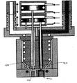
ここで図1を参照すると、バルブ開閉式射出成形システム100が示されている。システム100はノズル組み立て体102と作動システム104とを備える。ノズル組み立て体102の縦方向軸136が参考のために示されている。
Referring now to FIG. 1, a valve opening and closing
ノズル組み立て体102は公知の射出ノズルに多少類似した機能をし、ノズル本体138を有する。溶融物は、溶融物分配マニホールド122の第1マニホールド溶融物通路106および第2マニホールド溶融物通路108を介して、ノズル本体138の第1溶融物通路105および第2溶融物通路107に導入される。第1溶融物通路105内および第1マニホールド溶融物通路106内を流れる溶融物は、第2溶融物通路107内および第2マニホールド溶融物通路108内を流れる溶融物と同一材料でもよいし、また、2つの異なる材料が各組通路内を流れていてもよい。同様に、第1溶融物通路105および第1マニホールド溶融物通路106の直径は、第2溶融物通路107および第2マニホールド溶融物通路108の直径と同一でもよいし、また、2組の溶融物通路の直径は異なっていてもよい。このような設計事項は、システム100により製造される製造物の種類および/または実施される成形工程を主に考慮して決定される。
The
図1に示すように、第1マニホールド溶融物通路106は、第2マニホールド溶融物通路108よりもマニホールド122の出口側表面に近寄って配置されている。本発明の作用に必要でない一方で、マニホールド溶融物通路106,108をオフセットすることにより、追加の溶融物通路または分離したマニホールドの追加モジュラーを後で含めることが可能となる。溶融物を異なる温度に維持することを必要とする実質的に異なる溶融特性を有する2つの異なる材料が用いられる場合、分離したマニホールドが必要となるだろう。
As shown in FIG. 1, the first
マニホールド122をノズル組み立て体102に連結するのは溶融物コネクタ121である。溶融物コネクタ121は第1連結部溶融物通路123と第2連結部溶融物通路125とを有する。溶融物コネクタ121は、マニホールド溶融物通路106,108をノズル溶融物通路105,107に連結するために用いられるブッシングである。本実施の形態において、マニホールド溶融物通路106,108はマニホールド122の外部の周囲に向くように配置されている。ノズル溶融物通路105,107は、マニホールド溶融物通路106,108よりも縦方向軸136の近くに配置されている。したがって、第1連結部溶融物通路123は溶融物コネクタ121を斜めに貫通するように配置され、これにより第1連結部溶融物通路123は第1マニホールド溶融物通路106を第1ノズル溶融物通路105に流体連通させる。同様に、第2連結部溶融物通路125は溶融物コネクタ121を斜めに貫通するように配置され、これにより第2連結部溶融物通路125は第2マニホールド溶融物通路108を第2ノズル溶融物通路107に流体連通させる。
Connecting the
溶融物がノズル本体138の第1溶融物通路105内および第2溶融物通路107内を流れている間、溶融物の温度は加熱エレメント124により維持される。加熱エレメント124は、ノズル本体138に対して巻き付けられ、組み込まれ、締め付け固定されおよび/または鋳込まれてもよい。さらに、加熱エレメント124は、薄いまたは厚いフィルム状の加熱エレメントからなってもよい。溶融物は第1バルブゲート114および第2バルブゲート116を通過して型穴(図示せず)内に流れ込む。各バルブゲート114,116を通過する溶融物の流れは独立して制御される。第1バルブピン110が第1バルブゲート114内に嵌め込まれていない場合、第1バルブゲート114は開いている。同様に、第2バルブピン112が第2バルブゲート116内に嵌め込まれていない場合、第2バルブゲート116は開いている。図1Aは開いた状態にある第1バルブゲート114と閉じた状態にある第2バルブゲート116とを示している。
The temperature of the melt is maintained by the
第1バルブゲート114および第2バルブゲート116を通過する溶融物の流れは作動システム104により制御される。作動システム104はマニホールド122を挟んでノズル組み立て体102の反対側に配置されている。第1バルブピン110および第2バルブピン112はマニホールド122を通過して作動システム104内まで延在する。
The flow of the melt through the
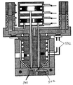
ここで図2を参照すると、第1バルブピン110の移動は第1作動ユニット118により制御されている。第1作動ユニット118は第1ピストン駆動機構204と第1ピストン208とを有しており、第1ピストン208はシリンダー217内でスライドすることができる。第1バルブピン110は第1バルブピン溝212内で軸方向に移動することができる。第1バルブピン溝212は第2作動ユニット120、マニホールド122および溶融物コネクタ121を貫通して延在する。
Referring now to FIG. 2, movement of the
第1ピストン駆動機構204は例えば空気圧または流体圧システム、ブラダピストン、またはカム・レバーシステムのように技術的に公知ないくつかの機構のいずれかでもよい。成形システムによる溶融物への加圧に関連した定期反復的な手順で圧力を加えたり開放したりするタイミング回路により制御されるバルブを介して、外部エア源をピストン駆動機構に接続することにより、空気圧駆動システムは動作する。流体圧駆動システムは空気圧システムと同じ方法で動作し、ただ空気を作動液に置き換えるだけである。 The first piston drive mechanism 204 may be any of a number of mechanisms known in the art such as, for example, a pneumatic or hydraulic system, a bladder piston, or a cam lever system. By connecting an external air source to the piston drive mechanism via a valve controlled by a timing circuit that applies and releases pressure in a periodic and repetitive procedure associated with pressurizing the melt by the molding system; The pneumatic drive system operates. Hydraulic drive systems operate in the same manner as pneumatic systems, only replacing air with hydraulic fluid.
他の実施形態においては、同一出願人により2002年3月14日に出願され、参照することによってこの中に全部組み込まれた同時継続中の米国出願60/363891に図示および記載されるように、第1駆動機構204はブラダピストンでもよい。ブラダピストンは拡張することができる細長くされたバッグであり、バッグは圧縮された、空気、水または油のような流動体を充填された場合に長さを縮める。ブラダが圧縮されると、ブラダは長さを収縮し、バルブピンがバルブゲートから外れて溶融物が型穴内へ流れ込むことができるように、ブラダの一端はバルブピンに取り付けられる。同様に、ブラダから圧力を抜くことにより、ブラダは長さを伸ばし、これによりバルブピンはバルブゲートに嵌め込まれ、型穴内への溶融物の流れを止める。 In another embodiment, as shown and described in co-pending US Application No. 60/363891, filed March 14, 2002 by the same applicant and incorporated herein by reference in its entirety, The first drive mechanism 204 may be a bladder piston. A bladder piston is an elongated bag that can be expanded, the bag shrinking in length when filled with a fluid, such as compressed air, water or oil. When the bladder is compressed, one end of the bladder is attached to the valve pin so that the bladder contracts in length and the valve pin disengages from the valve gate to allow the melt to flow into the mold cavity. Similarly, by releasing the pressure from the bladder, the bladder increases in length, whereby the valve pin snaps into the valve gate and stops the flow of melt into the mold cavity.
第1ピストン駆動機構204が手順を反復すると、第1ピストン208は上下に駆動される。これにより、第1バルブピン110は下方向および上方向に駆動され、この結果、第1バルブピン110は第1バルブゲート114内に嵌め込まれおよび第1バルブゲート114内から引き抜かれる。
When the first piston drive mechanism 204 repeats the procedure, the
作動システム104の縦方向軸216はノズル組み立て体102の縦方向軸136からわずかにオフセットされている。しかしながら、第1作動ユニット118の第1バルブピン110は縦方向軸216に中心合わせされている。
The
バルブピン110,112の移動を独立して制御するために必要となるスペースを最小化するため、第2作動ユニット120は第1作動ユニット118とマニホールド122との間に配置されている。第2作動ユニット120は第2ピストン駆動機構206と第2ピストン210とを有しており、第2ピストン210は第2シリンダー219内で移動することができる。第2バルブピン112は第2バルブピン溝214内で軸方向移動することができる。第2バルブピン溝214はマニホールド122と溶融物コネクタ121とを貫通して延在する。
The
第1バルブピン溝212は第2作動ユニット120を貫通しており、これにより第1バルブピン110は妨げられることなくノズル組み立て体102に達することができる。第2作動ユニット120を貫通する第1バルブピン溝212の配置を可能とするため、第2バルブピン112および第2バルブピン溝214は全長に渡って縦方向軸216からオフセットされている。図1Aに示すように、第2バルブピン112のオフセットされた位置決めにともなって、第2ピストン210の動作のバランスをとるため、ロッド140が第2ピストン上に配置されている。ロッド140は同様にダウエルでも、また類似する他の部品でもよい。
The first
第2ピストン駆動機構206は、第1ピストン駆動機構204を参照して上述したような多様な駆動機構のいずれかでもよい。第2ピストン駆動機構206が手順を反復すると、第2ピストン210は上下に駆動される。これにより、第2バルブピン112は下方向および上方向に駆動され、この結果、第2バルブピン112は第2バルブゲート116内に嵌め込まれおよび第2バルブゲート116内から引き抜かれる。
The second piston drive mechanism 206 may be any of a variety of drive mechanisms as described above with reference to the first piston drive mechanism 204. When the second piston drive mechanism 206 repeats the procedure, the
第1作動ユニット118および第2作動ユニット120のこのような配置により、第1バルブピン110縦方向中心軸と第2バルブピン112との間の間隔202を最小化することができる。間隔202は7mm以下までにすることができる。バルブピン110,112のこの密接間隔構成は、バルブゲート114,116の独立した動作を維持しながら、ノズル組み立て体102のバルブゲート114,116の密接配置を可能にする。
Such an arrangement of the
第1バルブゲート114および第2バルブゲート116から独立した制御を伴ったより多数のバルブゲートが望まれる場合、既存の作動ユニット上に追加の作動ユニットを積み重ねることができる。オフセットされた追加のバルブピン溝が第1作動ユニット118および第2作動ユニット120を通過して設けられるだろう。追加のバルブピンが不可欠なピストン動作のバランスをもたらすならば、ロッド140を削除することができる。
If more valve gates with control independent of the
各作動ユニットの積み重ねまたは横方向オフセットが求められようと求められまいと、多数配置されたバルブピンの各バルブピンに、ブラダピストン作動ユニットが活用されてもよい。 Whether or not a stacking or lateral offset of each actuation unit is required, a bladder piston actuation unit may be utilized for each of the multiple valve pins.
図3Aおよび図3Bは、小部品へのオーバーモールドに用いられる密接配置された2つのバルブゲート構成の一つの可能な応用例を示す。型穴302は、キャップのような2つの材料からなる小部品を成型できるように形成されている。第2の型穴306を形成するために、型コア304が型穴302内に配置されている。第2の型穴306は、開いた状態にある第2バルブゲート116を介して第1材料が充填される。第2材料が第2の型穴306内に入るのを防止するため、第1バルブゲート114は閉じた状態にある。
3A and 3B show one possible application of a closely spaced two valve gate configuration used for overmolding small parts. The mold hole 302 is formed so that a small component made of two materials such as a cap can be molded. A
図3Bはオーバーモールド工程の第2段階を示し、その中においては、型コア304はバルブゲート114,116から離れるように軸方向に移動されている。第2材料が第1バルブゲート114を介して型穴302内へ射出される。このとき、第1バルブゲート114は開いた状態にあり、第2材料の流出を可能としている。第2バルブゲート116は閉じた状態にあり、第1材料の型穴302へのさらなる射出を防止する。第2材料は成形された第1材料部分306aを覆い、2つの材料からなる一つのキャップが形成される。
FIG. 3B shows the second stage of the overmolding process, in which the
図4は本発明の別の応用例を示す。近接配置された同一な大きさおよび形状の2つの別個の型穴440,442を有する型とともに、本発明によるバルブ開閉式射出成形装置が示されている。本応用例においては、異なる色または異なる材料からなる2つの類似する物品を同時に成形することができる。何らかの理由で、ある色の部品を他の部品よりも多く成形する必要がある場合、2つのバルブピン410,412が独立して移動することができることから、ある種類の部品だけ反復して射出することができる。同様に、2つの材料が相違する成形特性、例えば粘性を有する場合、バルブピン410,412を異なる回数往復させることにより部品を成形することもできる。さらにまた、各穴内の第2の色/材料を射出する箇所へオーバーモールドするために、型穴440,442を左右に移動、または回転させることもできる。
FIG. 4 shows another application example of the present invention. A valve-closing injection molding apparatus according to the invention is shown with a mold having two separate mold cavities 440, 442 of identical size and shape arranged in close proximity. In this application, two similar articles of different colors or different materials can be molded simultaneously. If for some reason it is necessary to mold a part of a certain color more than another part, it is necessary to repeatedly inject only certain types of parts, since the two
図5は本発明の別の応用例を示す。近接配置された異なる大きさおよび形状の2つの別個の型穴540,542を有する型とともに、本発明によるバルブ開閉式射出成形装置が示されている。本応用例においては、同一または異なる色、および/または同一または異なる材料からなる2つの物品を同時に成形することができる。圧力センサ502がノズルおよび/またはマニホールドに設けられている。圧力センサ502は、圧力読み値に基づき、各ノズルの温度だけでなく、各溶融物通路内でのバルブピンの移動を制御するために用いられる。
FIG. 5 shows another application example of the present invention. A valve-closing injection molding apparatus according to the invention is shown with a mold having two
本発明による多様な実施形態を上述したが、それらは単なる例として提示されたものであり、限定されるものではないと理解されるべきである。関連技術に精通した者には、本発明の精神および範囲から離れることなく、形式上および細部について多様な変形を施すことができるのは明らかであるだろう。このように、本発明の幅および範囲は、上述した模範的な実施形態により制限されるべきではなく、特許請求の範囲および均等な範囲にのみ沿って画定されるべきである。 While various embodiments of the present invention have been described above, it should be understood that they have been presented by way of example only, and not limitation. It will be apparent to those skilled in the relevant art that various modifications in form and detail may be made without departing from the spirit and scope of the invention. Thus, the breadth and scope of the present invention should not be limited by any of the above-described exemplary embodiments, but should be defined only in accordance with the following claims and their equivalents.
Claims (19)
第1ゲートを選択的に開くための第1バルブ開閉部材と、
第2ゲートを選択的に開くための第2バルブ開閉部材と、
第1バルブ開閉部材に連結された第1作動機構と、
第2バルブ開閉部材に連結された第2作動機構と、
前記第1バルブ開閉機構および前記第2バルブ開閉機構を相対的に移動させるため、前記第1作動機構および前記第2作動機構を独立して駆動させる手段と、
を備えたことを特徴とする射出ノズル。 A nozzle body having a first melt passage and a second melt passage, wherein the first melt passage is offset from the second melt passage;
A first valve opening / closing member for selectively opening the first gate;
A second valve opening / closing member for selectively opening the second gate;
A first operating mechanism connected to the first valve opening / closing member;
A second operating mechanism connected to the second valve opening / closing member;
Means for independently driving the first operating mechanism and the second operating mechanism to relatively move the first valve opening and closing mechanism and the second valve opening and closing mechanism;
An injection nozzle comprising:
第1軸に沿って移動することができる、第1ゲートを選択的に開くための第1バルブ開閉部材と、
第2軸に沿って、第1バルブ開閉部材から独立して移動することができる、第2ゲートを選択的に開くための第2バルブ開閉部材と、を備え、
第1軸は第2軸からオフセットされていることを特徴とする射出ノズル。 A nozzle body having a first melt passage and a second melt passage;
A first valve opening / closing member for selectively opening the first gate, which is movable along a first axis;
A second valve opening and closing member for selectively opening the second gate, the second valve opening and closing member being movable along the second axis independently of the first valve opening and closing member;
An injection nozzle wherein the first axis is offset from the second axis.
第1溶融物の流れを受けるための第1溶融物通路と第2溶融物の流れを受けるための第2溶融物通路とを有し、第1溶融物通路は第2溶融物通路から軸方向にオフセットされたノズルと、
第1溶融物を型穴内に流し込むために、第1ゲートを選択的に開く第1バルブ開閉部材と、
第2溶融物を型穴内に流し込むために、第2ゲートを選択的に開く第2バルブ開閉部材と、を備え、
第2バルブ開閉部材は、第1バルブ開閉部材から独立して作動することができることを特徴とする射出成形装置。 A manifold having a first manifold melt passage for receiving a flow of a first melt of a moldable material, and a second manifold melt passage for receiving a flow of a second melt of a moldable material; ,
A first melt passage for receiving the flow of the first melt and a second melt passage for receiving the flow of the second melt, the first melt passage being axially displaced from the second melt passage; Nozzles offset to
A first valve opening / closing member that selectively opens the first gate for pouring the first melt into the mold cavity;
A second valve opening / closing member for selectively opening the second gate for pouring the second melt into the mold cavity;
The injection molding apparatus, wherein the second valve opening / closing member can operate independently of the first valve opening / closing member.
第1連結部溶融物通路は第1マニホールド溶融物通路と第1ノズル溶融物通路とに流体連通し、第2連結部溶融物通路は第2マニホールド溶融物通路と第2ノズル溶融物通路とに流体連通することを特徴とする請求項7記載の射出成形装置。 A melt passage connector provided between the manifold and the nozzle, the melt passage connector having a first connection portion melt passage and a second connection portion melt passage;
The first connection melt passage is in fluid communication with the first manifold melt passage and the first nozzle melt passage, and the second connection melt passage is in the second manifold melt passage and the second nozzle melt passage. The injection molding apparatus according to claim 7, wherein the apparatus is in fluid communication.
第1バルブ開閉部材と、
第2バルブ開閉部材と、
第1バルブ開閉部材に連結された第1作動機構と、
第2バルブ開閉部材に連結され、第1作動機構とノズル本体との間に配置され、第1バルブ開閉部材が規制されることなく貫通するように構成された第2作動機構と、
第1バルブ開閉機構および第2バルブ開閉機構を相対的に移動させるため、第1作動機構および第2作動機構を独立して駆動させる手段と、
を備えたことを特徴とする射出ノズル。 A nozzle body having a first nozzle melt passage and a second nozzle melt passage;
A first valve opening / closing member,
A second valve opening / closing member,
A first operating mechanism connected to the first valve opening / closing member;
A second operating mechanism connected to the second valve opening / closing member, disposed between the first operating mechanism and the nozzle body, and configured to penetrate the first valve opening / closing member without being restricted;
Means for independently driving the first operating mechanism and the second operating mechanism to relatively move the first valve opening and closing mechanism and the second valve opening and closing mechanism;
An injection nozzle comprising:
少なくとも1つの型穴への第1溶融材料および第2溶融材料の流れを制御することができる、独立して駆動される第1バルブ開閉部材および第2バルブ開閉部材と、
を備えたことを特徴とする射出成形装置。 A nozzle body having a first melt passage and a second melt passage in fluid communication with a manifold melt passage for directing the first molten material and the second molten material to the first valve gate and the second valve gate;
Independently driven first and second valve opening and closing members capable of controlling the flow of the first and second molten materials into the at least one mold cavity;
An injection molding apparatus comprising:
b) 第2バルブゲートを閉めた状態で第1バルブゲートを開くことにより、第1溶融材料が射出される第1型穴を準備する工程と、
c) 第2バルブゲートを開くことにより、第2溶融材料が射出される第2型穴を準備する工程と、
を備えたことを特徴とする2つの異なる材料からなる物品を成形する方法。 a) via a first valve gate and a second valve gate respectively controlled by laterally offset first and second opening and closing members driven by independent actuation means, respectively, through the first molten material and the second (2) providing an injection nozzle having a first melt passage and a second melt passage for feeding molten material;
b) preparing a first mold cavity into which the first molten material is injected by opening the first valve gate with the second valve gate closed;
c) preparing a second mold cavity into which the second molten material is injected by opening the second valve gate;
A method of molding an article made of two different materials, comprising:
Applications Claiming Priority (1)
| Application Number | Priority Date | Filing Date | Title |
|---|---|---|---|
| US42358502P | 2002-11-05 | 2002-11-05 |
Publications (3)
| Publication Number | Publication Date |
|---|---|
| JP2004155196A true JP2004155196A (en) | 2004-06-03 |
| JP2004155196A5 JP2004155196A5 (en) | 2005-12-22 |
| JP4489407B2 JP4489407B2 (en) | 2010-06-23 |
Family
ID=32108166
Family Applications (1)
| Application Number | Title | Priority Date | Filing Date |
|---|---|---|---|
| JP2003375910A Expired - Lifetime JP4489407B2 (en) | 2002-11-05 | 2003-11-05 | Closely arranged nozzle with individual valve opening and closing control |
Country Status (6)
| Country | Link |
|---|---|
| US (1) | US7192270B2 (en) |
| EP (1) | EP1418034B1 (en) |
| JP (1) | JP4489407B2 (en) |
| CN (1) | CN100408303C (en) |
| CA (1) | CA2448129C (en) |
| DE (1) | DE60311940T2 (en) |
Cited By (1)
| Publication number | Priority date | Publication date | Assignee | Title |
|---|---|---|---|---|
| JP2013173311A (en) * | 2012-02-27 | 2013-09-05 | Fuiisa Kk | Injection device of injection molding apparatus |
Families Citing this family (16)
| Publication number | Priority date | Publication date | Assignee | Title |
|---|---|---|---|---|
| US7648669B2 (en) * | 2004-11-30 | 2010-01-19 | Bemis Manufacturing Company | Injection-molding system and method |
| CA2540532A1 (en) * | 2005-04-25 | 2006-10-25 | Sulzer Chemtech Ag | An apparatus with a needle shut-off nozzle for an injection moulding machine |
| CN101088738B (en) * | 2006-06-16 | 2012-11-14 | 马斯特模具(2007)有限公司 | Open loop pressure control for injection molding |
| US7527490B2 (en) * | 2006-10-13 | 2009-05-05 | Mold-Masters (2007) Limited | Coinjection molding apparatus and related hot-runner nozzle |
| EP1935607B1 (en) * | 2006-12-21 | 2014-06-18 | Mold-Masters (2007) Limited | Valve for coinjection molding apparatus |
| US7658606B2 (en) * | 2006-12-22 | 2010-02-09 | Mold-Masters (2007) Limited | Edge gated injection molding apparatus |
| GB201021271D0 (en) * | 2010-12-15 | 2011-01-26 | Pilkington Group Ltd | Process and apparatus for moulding a glazing profile onto a glazing |
| CA2835045C (en) * | 2011-05-20 | 2016-08-09 | The Procter & Gamble Company | Non-naturally balanced feed system for an injection molding apparatus |
| CN102529024B (en) * | 2012-01-09 | 2014-04-30 | 东莞市凯昶德电子科技股份有限公司 | Self-locking nozzle for injection molding machine |
| US20150197049A1 (en) * | 2014-01-16 | 2015-07-16 | Otto Maenner Innovation Gmbh | Side gating hot runner nozzle and associated floating manifold seals |
| KR101936986B1 (en) * | 2015-01-28 | 2019-03-28 | 인글라스 에스피에이 | System and method for injection moulding of plastic materials |
| CN105500633B (en) * | 2016-01-27 | 2018-02-13 | 上海缔翊模具有限公司 | Multiple material mixed injection molding head and multiple material mixed injection molding mould |
| EP3651965B1 (en) * | 2017-07-14 | 2022-03-02 | Otto Männer GmbH | Injection molding device |
| KR102037356B1 (en) * | 2018-05-28 | 2019-10-28 | 허남욱 | Double piston Apparatus for operating a valve pin in a valve operated hot runner injection mold |
| CN114683494B (en) * | 2022-03-22 | 2025-08-15 | 东莞市热恒注塑科技有限公司 | Cylinder and hot runner system with same |
| CN117565332B (en) * | 2023-12-22 | 2024-06-11 | 太仓市众翔精密五金有限公司 | A secondary molding mold injection flow channel structure and injection molding device |
Family Cites Families (32)
| Publication number | Priority date | Publication date | Assignee | Title |
|---|---|---|---|---|
| US2418856A (en) * | 1939-06-20 | 1947-04-15 | French Oil Mill Machinery | Method of and apparatus for injection molding |
| CH566207A5 (en) * | 1972-12-07 | 1975-09-15 | Siemag Siegener Masch Bau | |
| DE2346135C2 (en) * | 1973-09-13 | 1982-11-04 | Battenfeld Maschinenfabriken Gmbh, 5882 Meinerzhagen | Method and device for the injection molding of plastic moldings which consist of a filling layer made of a thermoplastic material and a covering layer made of another thermoplastic material which encloses it |
| US4279582A (en) | 1979-04-02 | 1981-07-21 | Incoe Corporation | Method and apparatus for individual control of injection mold shut-off bushings |
| CA1174820A (en) | 1982-02-24 | 1984-09-25 | William J. Wiles | Injection molding valve pin direct pneumatic actuator |
| US4803031A (en) | 1982-06-03 | 1989-02-07 | Anchor Hocking Corporation | Method and apparatus for molding a closure cap |
| DE3245571C2 (en) | 1982-12-09 | 1985-04-11 | Männer, Otto, 7836 Bahlingen | Valve gate nozzle for injection molds |
| US5523045A (en) * | 1983-04-13 | 1996-06-04 | American National Can Company | Methods for injection molding and blow-molding multi-layer plastic articles |
| US4657496A (en) | 1984-06-04 | 1987-04-14 | Gifu Husky Co., Ltd. | Hot-runner mold for injection molding |
| DE3733363A1 (en) | 1987-10-02 | 1989-04-13 | Horst Prinz | Hot-runner needle-valve nozzle for processing thermoplastic materials |
| US5078589A (en) * | 1990-06-15 | 1992-01-07 | Osuna Diaz J M | Multicavity injection molding apparatus having precision adjustment and shut off of injection flow to individual mold cavities |
| US5223275A (en) * | 1990-10-12 | 1993-06-29 | Gellert Jobst U | Multi-cavity injection moulding system |
| JPH05507445A (en) * | 1991-02-12 | 1993-10-28 | 世紀株式会社 | Improved hot runner mold construction and its use |
| DE4206318C2 (en) * | 1992-02-29 | 1994-06-16 | Otto Maenner | Multiple needle valve nozzle for injection molds |
| DE4206319C2 (en) | 1992-02-29 | 1994-04-28 | Otto Maenner | Needle valve with piston drive |
| CA2068543C (en) | 1992-05-11 | 1999-11-09 | Jobst Ulrich Gellert | Coinjection molding apparatus having rotary axial actuating mechanism |
| JP3372979B2 (en) * | 1992-12-03 | 2003-02-04 | 東洋機械金属株式会社 | Control method of composite molding machine |
| US5372496A (en) * | 1993-02-18 | 1994-12-13 | Taniyama; Yoshihiko | Ejector valve plastic molding apparatus |
| EP0614744B1 (en) | 1993-02-25 | 1998-11-04 | Sony Electronics Inc. | Molding devices |
| DE4324275C2 (en) | 1993-07-20 | 1996-05-02 | Incoe Corp | Pneumatic control device for hot runner needle valves for injection molding tools |
| US5650178A (en) * | 1994-11-23 | 1997-07-22 | Bemis Manufacturing Company | Co-injection manifold for injection molding |
| CA2175634C (en) | 1996-05-02 | 2007-08-21 | Klaus Bauer | Injection molding valve member with head and neck portions |
| US5935621A (en) | 1997-01-24 | 1999-08-10 | Mold-Masters Limited | Injection molding apparatus having a cooled core |
| US5972258A (en) | 1997-10-20 | 1999-10-26 | Husky Injection Molding Systems Ltd. | Method of using a multiple gating nozzle |
| CA2219235C (en) * | 1997-10-23 | 2006-12-12 | Mold-Masters Limited | Five layer injection molding apparatus having four position valve member actuating mechanism |
| JP3225914B2 (en) | 1998-02-13 | 2001-11-05 | 三菱マテリアル株式会社 | Valve gate device and injection mold provided with this valve gate device |
| JP2000025072A (en) | 1998-07-13 | 2000-01-25 | Mitsubishi Materials Corp | Pin drive mechanism of valve gate device in injection mold |
| JP4062382B2 (en) * | 1998-07-16 | 2008-03-19 | 株式会社Ipm | Valve gate device |
| CA2264224A1 (en) | 1999-02-26 | 2000-08-26 | Denis Babin | Multi-cavity injection molding apparatus splitting melt near nozzle front |
| JP4024436B2 (en) | 1999-10-13 | 2007-12-19 | 柳道実業株式会社 | Resin injection device for injection molding machine that operates many valve pins with one piston |
| JP2002036310A (en) * | 2000-07-25 | 2002-02-05 | Mitsubishi Materials Corp | Method for forming microrelay member and valve gate device used in this method |
| EP1762359B1 (en) * | 2002-12-03 | 2009-07-15 | Mold-Masters (2007) Limited | Hot runner co-injection nozzle |
-
2003
- 2003-11-05 EP EP03025448A patent/EP1418034B1/en not_active Expired - Lifetime
- 2003-11-05 CN CNB2003101198153A patent/CN100408303C/en not_active Expired - Lifetime
- 2003-11-05 US US10/700,521 patent/US7192270B2/en not_active Expired - Lifetime
- 2003-11-05 DE DE60311940T patent/DE60311940T2/en not_active Expired - Lifetime
- 2003-11-05 CA CA2448129A patent/CA2448129C/en not_active Expired - Lifetime
- 2003-11-05 JP JP2003375910A patent/JP4489407B2/en not_active Expired - Lifetime
Cited By (1)
| Publication number | Priority date | Publication date | Assignee | Title |
|---|---|---|---|---|
| JP2013173311A (en) * | 2012-02-27 | 2013-09-05 | Fuiisa Kk | Injection device of injection molding apparatus |
Also Published As
| Publication number | Publication date |
|---|---|
| JP4489407B2 (en) | 2010-06-23 |
| CN1526538A (en) | 2004-09-08 |
| CA2448129C (en) | 2012-01-03 |
| US7192270B2 (en) | 2007-03-20 |
| CN100408303C (en) | 2008-08-06 |
| EP1418034A1 (en) | 2004-05-12 |
| CA2448129A1 (en) | 2004-05-05 |
| DE60311940D1 (en) | 2007-04-05 |
| EP1418034B1 (en) | 2007-02-21 |
| DE60311940T2 (en) | 2007-06-14 |
| US20040091569A1 (en) | 2004-05-13 |
Similar Documents
| Publication | Publication Date | Title |
|---|---|---|
| JP4489407B2 (en) | Closely arranged nozzle with individual valve opening and closing control | |
| CA2878559C (en) | Coinjection molding apparatus and related hot-runner nozzle | |
| US6575731B1 (en) | Apparatus for distributing melt in a multi-level stack mold | |
| JP4889862B2 (en) | Multilayer injection molding apparatus and method | |
| JP4927880B2 (en) | Co-injection nozzle assembly device | |
| CN101932424A (en) | Injection molding apparatus with magnetic valve pin coupling | |
| JP2005132079A (en) | Heating runner coextrusion nozzle | |
| EP1806218B1 (en) | Valve-gated injection molding apparatus for side gating | |
| JP2004130787A (en) | Improved molten material transfer device between valves | |
| CN108454011A (en) | Hot flow path injection nozzle and actuator for injection-molding apparatus | |
| US7029269B2 (en) | In-line valve gated nozzle | |
| KR100822124B1 (en) | Removable injection molding injection port assembly with check valve | |
| JP7503417B2 (en) | Injection molding equipment equipped with hot runners | |
| KR101543596B1 (en) | A hot runner device for double injection molding | |
| JP2002127202A (en) | Valve gate assembly for injection molding | |
| JP2003340878A (en) | Hot runner type mold device | |
| JP3046629B2 (en) | Purge device in hot runner mold | |
| JP2003245949A (en) | Valve gate type mold equipment |
Legal Events
| Date | Code | Title | Description |
|---|---|---|---|
| A521 | Request for written amendment filed |
Free format text: JAPANESE INTERMEDIATE CODE: A523 Effective date: 20051102 |
|
| A621 | Written request for application examination |
Free format text: JAPANESE INTERMEDIATE CODE: A621 Effective date: 20051102 |
|
| A977 | Report on retrieval |
Free format text: JAPANESE INTERMEDIATE CODE: A971007 Effective date: 20080529 |
|
| A131 | Notification of reasons for refusal |
Free format text: JAPANESE INTERMEDIATE CODE: A131 Effective date: 20080603 |
|
| A601 | Written request for extension of time |
Free format text: JAPANESE INTERMEDIATE CODE: A601 Effective date: 20080903 |
|
| A602 | Written permission of extension of time |
Free format text: JAPANESE INTERMEDIATE CODE: A602 Effective date: 20080908 |
|
| A521 | Request for written amendment filed |
Free format text: JAPANESE INTERMEDIATE CODE: A523 Effective date: 20081003 |
|
| A711 | Notification of change in applicant |
Free format text: JAPANESE INTERMEDIATE CODE: A711 Effective date: 20081010 |
|
| A131 | Notification of reasons for refusal |
Free format text: JAPANESE INTERMEDIATE CODE: A131 Effective date: 20091106 |
|
| A521 | Request for written amendment filed |
Free format text: JAPANESE INTERMEDIATE CODE: A523 Effective date: 20100205 |
|
| TRDD | Decision of grant or rejection written | ||
| A01 | Written decision to grant a patent or to grant a registration (utility model) |
Free format text: JAPANESE INTERMEDIATE CODE: A01 Effective date: 20100302 |
|
| A01 | Written decision to grant a patent or to grant a registration (utility model) |
Free format text: JAPANESE INTERMEDIATE CODE: A01 |
|
| A61 | First payment of annual fees (during grant procedure) |
Free format text: JAPANESE INTERMEDIATE CODE: A61 Effective date: 20100331 |
|
| FPAY | Renewal fee payment (event date is renewal date of database) |
Free format text: PAYMENT UNTIL: 20130409 Year of fee payment: 3 |
|
| R150 | Certificate of patent or registration of utility model |
Ref document number: 4489407 Country of ref document: JP Free format text: JAPANESE INTERMEDIATE CODE: R150 Free format text: JAPANESE INTERMEDIATE CODE: R150 |
|
| FPAY | Renewal fee payment (event date is renewal date of database) |
Free format text: PAYMENT UNTIL: 20140409 Year of fee payment: 4 |
|
| R250 | Receipt of annual fees |
Free format text: JAPANESE INTERMEDIATE CODE: R250 |
|
| R250 | Receipt of annual fees |
Free format text: JAPANESE INTERMEDIATE CODE: R250 |
|
| R250 | Receipt of annual fees |
Free format text: JAPANESE INTERMEDIATE CODE: R250 |
|
| R250 | Receipt of annual fees |
Free format text: JAPANESE INTERMEDIATE CODE: R250 |
|
| R250 | Receipt of annual fees |
Free format text: JAPANESE INTERMEDIATE CODE: R250 |
|
| R250 | Receipt of annual fees |
Free format text: JAPANESE INTERMEDIATE CODE: R250 |
|
| R250 | Receipt of annual fees |
Free format text: JAPANESE INTERMEDIATE CODE: R250 |
|
| R250 | Receipt of annual fees |
Free format text: JAPANESE INTERMEDIATE CODE: R250 |
|
| R250 | Receipt of annual fees |
Free format text: JAPANESE INTERMEDIATE CODE: R250 |
|
| R250 | Receipt of annual fees |
Free format text: JAPANESE INTERMEDIATE CODE: R250 |
|
| R250 | Receipt of annual fees |
Free format text: JAPANESE INTERMEDIATE CODE: R250 |
|
| EXPY | Cancellation because of completion of term |