JP2004227251A - Electronics - Google Patents
Electronics Download PDFInfo
- Publication number
- JP2004227251A JP2004227251A JP2003013853A JP2003013853A JP2004227251A JP 2004227251 A JP2004227251 A JP 2004227251A JP 2003013853 A JP2003013853 A JP 2003013853A JP 2003013853 A JP2003013853 A JP 2003013853A JP 2004227251 A JP2004227251 A JP 2004227251A
- Authority
- JP
- Japan
- Prior art keywords
- state
- main body
- display unit
- unit
- electronic device
- Prior art date
- Legal status (The legal status is an assumption and is not a legal conclusion. Google has not performed a legal analysis and makes no representation as to the accuracy of the status listed.)
- Pending
Links
Images


Classifications
-
- G—PHYSICS
- G08—SIGNALLING
- G08B—SIGNALLING SYSTEMS, e.g. PERSONAL CALLING SYSTEMS; ORDER TELEGRAPHS; ALARM SYSTEMS
- G08B5/00—Visible signalling systems, e.g. visible personal calling systems or remote indication of seats occupied
- G08B5/22—Visible signalling systems, e.g. visible personal calling systems or remote indication of seats occupied using electric transmission; using electromagnetic transmission
- G08B5/36—Visible signalling systems, e.g. visible personal calling systems or remote indication of seats occupied using electric transmission; using electromagnetic transmission using visible light sources
-
- H—ELECTRICITY
- H01—ELECTRIC ELEMENTS
- H01H—ELECTRIC SWITCHES; RELAYS; SELECTORS; EMERGENCY PROTECTIVE DEVICES
- H01H2219/00—Legends
- H01H2219/036—Light emitting elements
- H01H2219/039—Selective or different modes of illumination
-
- H—ELECTRICITY
- H01—ELECTRIC ELEMENTS
- H01H—ELECTRIC SWITCHES; RELAYS; SELECTORS; EMERGENCY PROTECTIVE DEVICES
- H01H2239/00—Miscellaneous
- H01H2239/016—Miscellaneous combined with start switch, discrete keyboard
-
- H—ELECTRICITY
- H01—ELECTRIC ELEMENTS
- H01H—ELECTRIC SWITCHES; RELAYS; SELECTORS; EMERGENCY PROTECTIVE DEVICES
- H01H2300/00—Orthogonal indexing scheme relating to electric switches, relays, selectors or emergency protective devices covered by H01H
- H01H2300/022—Application wake up; switches or contacts specially provided for the wake up or standby shift of a circuit
Landscapes
- Physics & Mathematics (AREA)
- Electromagnetism (AREA)
- General Physics & Mathematics (AREA)
- Power Sources (AREA)
Abstract
【課題】ユーザに電源の状態を容易に把握させるとともに、電源スイッチの位置を容易に判別させる。
【解決手段】ノートPCが起動状態にあり、LEDが青色に点灯している場合において、LCDが表示するOSのメニュー画面にしたがって、キーボードにより、ノートPCをサスペンド状態に切り替えるためのスタンバイコマンド、またはノートPCをシャットダウン状態に切り替えるためのシャットダウンコマンドを入力する。スタンバイコマンドを入力すると、EC(エンベデッドコントローラ)は、BIOSを介して、レジスタの制御用情報を、サスペンド状態を示す情報に書き換える。ECは、レジスタの制御用情報に従い、LEDにより黄色の光を点灯させる。
【選択図】 図5A user can easily grasp a state of a power supply and easily determine a position of a power switch.
A standby command for switching a notebook PC to a suspend state by using a keyboard according to a menu screen of an OS displayed on an LCD when the notebook PC is in an active state and an LED is lit in blue, or A shutdown command for switching the notebook PC to a shutdown state is input. When a standby command is input, an EC (embedded controller) rewrites control information of the register to information indicating a suspended state via the BIOS. The EC causes the LED to emit yellow light according to the control information in the register.
[Selection diagram] FIG.
Description
【0001】
【発明の属する技術分野】
本発明は、例えばノート型パーソナルコンピュータなどの電子機器に関する。
【0002】
【従来の技術】
従来の、例えばノート型のコンピュータなどの電子機器には、電源スイッチのオンオフに伴った電源供給状態に応じて点灯または消灯するLED(LightEmitting Diode)を備えたものが存在する。このLEDは、電源スイッチを押下して電源が投入された場合に例えば緑色に点灯し、電源が遮断された場合には消灯する(特許文献1)。
【0003】
【特許文献1】
特開2000−306449号公報(第1頁、第1図)
【0004】
【発明が解決しようとする課題】
しかしながら、上記LEDは、電源スイッチの押下にしたがって点灯または消灯するものであり、電源の投入状態または遮断状態の2種類の状態を表示するのみである。よって、例えばノートPC特有のスタンバイ(サスペンド)状態などの節電時の待機状態を表示することができない。また、このようなLEDは、電源スイッチとは別体でノートPC本体の異なる場所に設けられている。この場合、LEDにより電源状態を確認後、電源スイッチの場所を探して、電源投入を行う必要がある。このため、電源スイッチの場所をユーザが容易に認識可能な場所に配置することが望ましいという要求もある。
【0005】
本発明は、上記の問題を解決するためになされたものであり、ユーザが電子機器の電源の状態を容易に把握することが可能でかつ電源スイッチの場所を容易に認識可能な電子機器を提供することを目的とする。
【0006】
【課題を解決するための手段】
前記目的を達成するため、本発明の請求項1に係る電子機器は、第1の状態と第2の状態で動作可能な本体と、前記本体に設けられ、少なくとも一部が透光部材で構成された電源スイッチと、前記本体内に設けられ、前記透光部材を介して第1の色または第2の色で発光される発光手段と、前記本体の動作状態が第1の状態である場合、前記発光手段を前記第1の色で発光させ、前記本体の動作状態が第2の状態である場合、前記発光手段を前記第2の色で発光させる制御手段とを具備したことを特徴とする。
【0007】
このような構成とすれば、電子機器の動作状態に応じて、発光手段を所定の色で発光させることにより、電子機器の状態を把握可能になると供に、電源スイッチの場所も把握可能となる。
【0008】
また、本発明の請求項10に係る電子機器では、本体と、前記本体の上面を覆う第1の位置と前記本体の上面を露出させる第2の位置との間で回動可能に接続される表示部と、前記本体に設けられ前記本体の動作状態に基づき発光する発光手段と、前記表示部が前記第1の位置であるか前記第2の位置であるかを検出する検出手段とを具備し、前記検出手段により前記表示部が前記第1の位置であると検出された場合、前記発光手段を消灯することを特徴とする。
【0009】
このような構成によれば、電子機器の動作状態に応じて、発光手段を発光させることで電子機器の動作状態を把握可能としながら、且つ表示部が閉じられた場合には発光手段を消灯し省電力化を測ることが可能な電子機器を提供することが可能となる。
【0010】
また、本発明の請求項11に係る電子機器では、本体と、前記本体の上面を覆う第1の位置と前記本体の上面を露出させる第2の位置との間で回動可能に接続される表示部と、前記本体に設けられ前記本体の動作状態に基づき発光する発光手段と、前記表示部が前記第1の位置であるか前記第2の位置であるかを検出する検出手段と、時間の経過を計時するカウント手段を具備し、前記表示部が前記第2の位置であると検出され、前記カウント手段により、前記第2の位置に移行してから所定時間経過したことが検出された場合、前記発光手段を消灯することを特徴とする。
【0011】
このような構成によれば、電子機器の動作状態に応じて、発光手段を発光させることで電子機器の動作状態を把握可能としながら、且つ表示部が開けられている状態でも、所定時間後に発光手段を消灯することで省電力化を図ることが可能な電子機器を提供することが可能となる。
【0012】
【発明の実施の形態】
以下本発明をノート型のパーソナルコンピュータ(以下、ノートPCと称する)に適用した場合の実施形態について図面を参照して説明する。
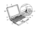
図1は、本発明の実施形態に係わるノートPCの外観図である。
図1に示したように、本実施形態のノートPCは、本体ケース1、表示部ケース2およびヒンジ部3を有する。ヒンジ部3は、表示部ケース2を回転軸(図示せず)を中心に、キーボード4を覆う閉状態と、キーボード4を使用可能な状態に露出させる開状態との間で回動可能に支持する。
【0013】
本体ケース1の上面1aにはユーザからの入力手段となるキーボード4と、キーボード4とヒンジ部3との間のスペースには、半透明な部材で構成される電源スイッチ11が設けられている。表示部ケース2は、表示デバイスであるLCD(Liquid Crystal Display:液晶ディスプレイ)5の周辺部を内側から可視可能に支持しており、このことによりLCD5はその表示面が可視可能に設けられている。本体ケース1内の電源スイッチ11のスイッチ面と対向する位置にはLED(Light Emitting Diode:発光ダイオード)12が設けられている。本実施形態ではLED12は、3色に発光可能であり、ノートPCの電源の状態にしたがって、青色、橙色または黄色のいずれかの色の光または全ての色を混合させた光を発する。電源スイッチ11は半透明部材(または透明部材)により構成されているので、LED12が発光することにより、電源スイッチ11を透過して光が放射される。本実施形態では、電源スイッチ11を本体ケース1の上面1aの、キーボード4の上方に設けられたスペースに配置した。これは、ユーザが通常キーボード4の操作を行う際に手が触れない位置であり、且つパソコン使用時にLCD5からの視線移動が少なく、視野に入る位置であることを考慮したものである。このように上面1aに設けることで、表示部ケース2が開状態であれば、電源スイッチ11(LED12)の発光色に基づいて、ユーザはノートPCのシステム状態を認識可能となる。但し、電源スイッチ11を設ける箇所は、本体ケース1の上面1aに限らず、例えば、表示部ケース2の前面2aなどに設けても差し支えない。また、LED12を設ける箇所は、電源スイッチ11のスイッチ面と対向する位置に限らず、LED12の発光した際の光が電源スイッチ11の面を透過可能な位置なら良い。
【0014】
本実施形態のノートPCは、電源の状態にしたがって、LED12が発する光の色を変更する機能を有する。電源の状態とは、例えば、ノートPCの電源が投入されている状態(以下、起動状態と称する)、ノートPCが一時的に動作を停止している状態(以下、サスペンド状態と称する)、およびOSが終了してノートPCの動作が停止された状態(以下、シャットダウン状態と称する)を示す。
【0015】
本実施形態では、LED12は、起動状態では青色に点灯し、サスペンド状態では黄色に点灯し、また、シャットダウン状態では、橙色に点灯するものとする。このLED12から発せられる光が半透明部材で形成された電源スイッチ11を透されることにより、ユーザはノートPCの状態を容易に把握でき、且つ電源スイッチ11が設けられている場所を容易に認識可能となる。なお、LED12の発する光の色については特に限定されるものではない。
【0016】
図2は、図1に示したノートPCの本体ケース1の電源スイッチ11およびその周辺の断面図である。
図2に示すように、基板10には、電源スイッチ11、LED12、電源スイッチ押下検出部15、筐体カバー16、エンベデッドコントローラ(Embedded Controller:以後、ECと称す)17が設けられる。電源スイッチ11は、弾性部材により本体ケース1内方向から本体ケース1外方向へ付勢されており、押下されていない状態では、本体ケース1の上面1aとほぼ同一平面状に位置するように設けられている。また、電源スイッチ11が押下され、その後電源スイッチ11が離された場合などは、弾性部材により本体ケース1の上面1aとほぼ同一平面上となる位置へ戻る。本実施形態では、電源スイッチ11は、例えばスプリングを介在して基板10に取り付けられる。
【0017】
電源スイッチ11の下部にはスイッチ端子14が設けられており、スイッチ端子14は、電源スイッチ11の押下に応じて電源スイッチ押下検出部15と接触する。電源スイッチ押下検出部15は、基板10に設けられており、スイッチ端子14が接触すると電源スイッチ11が押下されたことに応じた信号をEC17へ送出する。
【0018】
EC17は、電源スイッチ押下検出部15からの信号を受信すると、ノートPCのシステム状態を判断し、LED12の発光色を制御する。
【0019】
電源スイッチ11には中央部に半透明部材により構成された透過カバー13が設けられている。この透過カバー13は、例えばプラスチックやガラスなどにより形成された半透明もしくは透明な部材である。透過カバー13は、LED12により発せられた光を上方に透過可能であり、ユーザから見た場合、電源スイッチ11が発光したように視認される。本実施形態では、電源スイッチ11の中央部を透過カバー13により形成しているが、電源スイッチ11の周端部のみ透過部材により構成したり、電源スイッチ11の面全てを透過カバーにより形成しても構わない。
【0020】
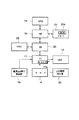
図3は、図1に示したノートPCの内部の回路の構成を示すブロック図である。
図3では、ノートPCにおいて、本発明に関連する部分のみについて図示する。図3に示すように、ノートPCには、このノートPC全体の制御を司るCPU18が設けられている。CPU18には、NB(ノースブリッジ)19が接続され、NBにはSB(サウスブジッジ)20が接続されている。また、NB19には、CPU18動作時のワークエリアとなるメインメモリ21が接続される。メインメモリ21には、システム動作中に入出力デバイスの制御を行ったりノートPCの基本入出力制御を実行するBIOS21aが記憶されている。これは、ノートPCの起動時に図示しないBIOS−ROMから読み出されて、メインメモリ21へコピーされるものであり、ノートPC起動後は主にメインメモリ21内のBIOS21aにより基本入出力制御及び電源状態の管理が行われる。
【0021】
SB20には、HDD(ハードディスクドライブ)23が接続される。HDD23は、不揮発性の記憶媒体であり、ノートPCの電源が投入されていない状態でデータを記憶可能なデバイスである。このHDD23は、OSおよびアプリケーションソフトウェアなどが記憶されており、これらのソフトウェアを実行する際は適宜メインメモリ21に展開される。NB19は、例えばCPU18とNB19に接続されるデバイスとの間のデータ及びアドレス変換などの処理を実行するブリッジ回路である。SB20は、SB20を介して接続されるデバイス間でデータの入出力処理などを実行するブリッジ回路である。SB20から延出されるバスには、EC17が接続される。EC17は、CPU18からリード/ライト可能なレジスタ17aを有する。EC17には、電源スイッチ押下検出部15、キーボード4、LED12およびLCD開閉検出部22が接続されている。LCD開閉検出部22は、例えば図1に示した本体ケース1の上面1aに設けられている。この開閉検出部22は弾性部材により本体ケース1の内部から上面1a方向へ弾性部材により付勢されて設けられた突出部材であり、表示部ケース2の開閉に応じて上下方向に摺動可能である。表示部ケース2が開状態から閉状態へ回動されると、LCD開閉検出部22は表示部ケース2に押下され下方へ摺動されることにより、表示部ケース2が開状態から閉状態へ遷移されたことを検出する。また、表示部ケース2が閉状態から開状態へ回動されると、LCD開閉検出部22は表示部ケース2による押圧がなくなるため、弾性部材により上方へ摺動され、表示部ケース2が閉状態から開状態へ遷移されたことを検出する。上述のように、LCD開閉検出部22により表示部ケース2の開閉状態が検出される。レジスタ17aは書き換え可能なメモリである。レジスタ17aは、特に、LED12の点灯及びその際の発光色を決定する処理(以下、LED点灯処理と称する)に係る制御処理用ソフトウェアを記憶する。また、レジスタ17aは、LED12の発光処理に係るノートPCの状態を記憶する。また、EC17は、ノートPCの状態に応じてBIOS21aの制御の元、CPU18によりレジスタ17aが書き換えられる。また、LED点灯処理に係る制御ソフトウェアは、EC17が内蔵するROMに記憶されていても良い。
【0022】
次に、本実施形態のノートPCによるLED発光に係わる処理について説明する。
まず、ノートPCがシャットダウン状態から起動状態に切り替わった場合のLED点灯処理(以下、第1のLED点灯処理と称する)について説明する。
図4は、図1に示したノートPCが実行する第1のLED点灯処理の内容を示すフローチャートである。
ここで、ノートPCはシャットダウン状態であると仮定する。この状態では、LED12は橙色に点灯しており(ステップS1)、電源スイッチ11は橙色に発光されている。次に、電源スイッチ11を押下する。すると、スイッチ端子14が電源スイッチ押下検出部15に接触する。電源スイッチ押下検出部15は、電源スイッチ押下検出部15にスイッチ端子14が接触すると、これを検出する(ステップS2)。電源スイッチ押下検出部15は、駆動制御信号をEC17に出力する。この駆動制御信号は、電源スイッチ11が押下されたことを示す情報を含んでいる。EC17は、駆動制御信号を入力すると、LED12を青色、橙色、黄色を全て点灯させ(ステップS3)。ユーザには3色発光することにより白色に近い光が点灯したように見えることになる。
【0023】
次に、押下した電源スイッチ11を離すと、スイッチ端子14が電源スイッチ押下検出部15から離れる。電源スイッチ押下検出部15は、スイッチ端子14が離れると、これを検出する(ステップS4)。電源スイッチ押下検出部15は、駆動制御信号をEC17に出力する。この駆動制御信号は、電源スイッチ11が、該電源スイッチ11を押下する以前の位置に復帰したことを示す情報を含んでいる。EC17は、駆動制御信号を入力すると、ノートPCが起動状態に切り替わったと判別し、BIOS21aを介して、レジスタ17aの制御用情報を、起動状態を示す情報に書き換える。EC17は、レジスタ17aの制御用情報に従い、LED12により青色の光を点灯させる(ステップS5)。
【0024】
これにより、ユーザは、電源スイッチ11が内蔵するLED12の発光色に基づいて、ノートPCがシャットダウン状態から起動状態に切り替わったことを容易に認識することができる。また、半透明部材で形成された電源スイッチ11を本体ケース1の上面1aに設け、且つその下方にLED12を設けることで、特に視点を変えることなく電源の状態を認識できるようになる。
【0025】
上述の例では、電源スイッチ11が押された場合、離された場合それぞれの場合に応じて、スイッチが押されたか否かの信号が出力されているが、例えば“1”、“0”の二値信号で、スイッチが押された場合は“1”の信号(所定の電圧レベル)を出力し、スイッチが押されていない状態では“0”の信号(電圧レベルゼロ)といった信号EC17へ出力することにより、EC17でスイッチの押下を検出することも可能である。
【0026】
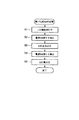
次に、ノートPCが起動状態からサスペンド状態またはシャットダウン状態に切り替わった場合のLED点灯処理(以下、第2のLED点灯処理と称する)について説明する。
図5は、図1に示したノートPCが実行する第2のLED点灯処理の内容を示すフローチャートである。
ここで、ノートPCは起動状態であると仮定する。この状態では、LED12は青色に点灯している(ステップS11)。ここで、例えばLCD5が表示するOSのメニュー画面にしたがって、キーボード4により、ノートPCをサスペンド状態に切り替えるためのコマンド(以下、スタンバイコマンドと称する)、またはノートPCをシャットダウン状態に切り替えるためのコマンド(以下、シャットダウンコマンドと称する)を入力する。
【0027】
OSのメニュー画面でスタンバイコマンドが入力された場合(ステップS12のYES)、CPU18はBIOS21aの制御の元、EC17内のレジスタ17aの制御用情報を、サスペンド状態を示す情報に書き換える(ステップS13)。EC17は、OSがサスペンド状態に移行した後(ステップS14)、レジスタ17aの制御用情報に従い、LED12を黄色点灯させる(ステップS15)。
【0028】
一方、OSのメニュー画面でシャットダウンコマンドが入力された場合(ステップS12のNOからステップS16のYES)、CPU18はBIOS21aの制御の元、レジスタ17aの制御用情報を、シャットダウン状態を示す情報に書き換える(ステップS17)。EC17は、ノートPCが電源オフ状態になった後(ステップS18)、レジスタ17aの制御用情報に従い、LED12を橙色の光で点灯させる(ステップS19)。
【0029】
これにより、ユーザは、OSコマンド入力によりノートPCが起動状態からサスペンド状態またはシャットダウン状態に切り替わった場合に、夫々の状態を容易に把握することが可能である。
【0030】
また、本実施形態のノートPCは、既に説明した第1の電源スイッチ11の押下に伴う第1のLED点灯処理またはコマンド入力による第2のLED点灯処理を、表示部ケース2の開閉状態に従って実行又は停止させる機能(以下、LED点灯処理の開閉連動機能と称する)を有している。
【0031】
開閉連動機能は、ノートPCが開状態にある場合には、第1のLED点灯処理および第2のLED点灯処理を実行させ、ノートPCが閉状態にある場合にはLED12の点灯を停止させる機能である。ノートPCが閉状態にある場合には、電源スイッチ11は表示部ケース2に覆われることにより、LED12の点灯状態を見ることができない。つまり、閉状態において、LED12を点灯させておくことは、ノートPCのバッテリの無駄な消費の原因となり、且つLED12およびその他の部品の特性の無用な劣化を引き起こす原因となる。開閉連動機能は、上記説明した問題を解消することを目的として搭載された機能である。開閉連動機能は、開閉連動機能用の制御プログラムを例えばEC17に記憶させて実行させることで実現される。
【0032】
図6は、図1に示したノートPCによるLED点灯処理の開閉連動機能の内容を示すフローチャートである。
まず、LCD開閉検出部22は、ノートPCが閉状態または開状態のいずれにあるかを検出する。LCD開閉検出部22は、ノートPCが開状態であることを検出すると、駆動制御信号をEC17に出力する(ステップS21→S22)。EC17は、駆動制御信号を入力すると、レジスタ17aに書込まれている制御用情報を参照して電源の状態を認識する(ステップS23)。電源の状態は既に説明したように、起動状態、サスペンド状態およびシャットダウン状態のいずれかである。各状態に対応する表示色は既に説明したとおりである。そして、決定した表示色の光をLED12により出力させる(ステップS25)。
【0033】
一方、LCD開閉検出部22は、表示部ケース2が開状態から閉状態へ移行されたことを検出すると、駆動制御信号をEC17に出力する(ステップS21→S26)。EC17は、駆動制御信号を入力すると、電源の状態に関係なく、LED12を消灯させる(ステップS27)。
【0034】
以上説明したように、LED点灯処理の開閉連動機能を用いると、バッテリの無駄な消費、およびLED12とその他の部品特性の無用な劣化を防止することができる。
【0035】
次に本実施形態のノートPCが有するタイマカウント機能について説明する。
タイマカウント機能は、第1のLED点灯処理および第2のLED点灯処理が実行され、LED12が青色、黄色または橙色に点灯した後に一定時間が経過すると、該LED12を消灯させる機能である。
【0036】
ユーザは、青色、黄色または橙色に点灯した電源スイッチ11(LED12)により現在の電源の状態を認識可能であるが、この認識した状態をユーザが記憶していれば、LED12を常時点灯させておく必要はなく、LED12を消灯させることでバッテリ電力の無駄な消費を防止することが可能となる。タイマカウント機能は、タイマカウント用の制御プログラムを例えばEC17に記憶させて、これを実行させることで実現される。
【0037】
図7は、図1に示したノートPCによるタイマカウント機能の内容を示すフローチャートである。
まず、第1のLED点灯処理および第2のLED点灯処理において、LED12発する光の色が切り替わる、もしくは消灯した状態から特定の色の光が発せられると、タイマカウントを開始する(ステップS31,S32)。タイマカウントが開始されて所定時間(本実施形態では、例えば1分間)が経過すると、EC17は、発する光の色に関係なくLED12を消灯させる(ステップS32→S33)。
【0038】
また、上述の例では、ノートPCの状態(点灯色)に関わらず、所定時間が経過した後にLED12を消灯しているが、例えば電源オン状態の場合は常時点灯させておき、サスペンド状態、シャットダウン状態の時のみ、所定時間が経過したら消灯させるようにしても良い。これは、例えばノートPCがバッテリにより駆動されている場合はノートPCの状態(点灯色)に関わらず、所定時間が経過した後にLED12を消灯し、ノートPCがACアダプタのような商用電源により駆動されている場合は特定状態(上記の例ではノートPCが電源オン状態)の時のみLED12を常時点灯させ、その他の状態の場合は所定時間経過後にLED12を消灯させるといった切換え制御も可能である。これは、図示しない電源マイコンにより電源供給元を判断し、EC17へ信号を送出し、EC17により制御される。
【0039】
以上説明したように、タイマカウント機能を用いると、バッテリの無駄な消費、およびLED12とその他の部品特性の無用な劣化を防止することができる。
【0040】
本実施形態のノートPCは、第1のLED点灯処理に係る機能、第2のLED点灯処理に係る機能、当該第1,第2のLED点灯処理の開閉連動機能またはタイマカウント機能の実行の有無を機能別に選択することができる。この選択に係る処理は、例えば、HDD23に各種機能の実行の有無を選択する機能を有したソフトウェアを記憶し、このソフトウェアを起動して、実行の有無に係る選択画面をLCD5に表示させ、この選択画面にしたがってキーボード4により実行の有無を選択するコマンドを入力することで実現される。
【0041】
次に、本実施形態において、開閉連動機能とタイマカウント機能とをともに用いた場合の動作について説明する。ノートPCが開状態から閉状態に切り替わった場合には、開閉連動機能により第1および第2のLED点灯処理が停止し、ノートPCが閉状態から開状態に切り替わった場合には、開閉連動機能により第1および第2のLED点灯処理が実行された上で、タイマカウント機能により1分間のタイマカウント後、LED12が消灯する。
【0042】
このように、本実施形態によれば、ノートPCの電源の状態の変化に応じて、LED12の発光色を変化させるので、ユーザが電源の状態を容易に把握することが可能であり、且つ電源スイッチ12の場所も認識可能となる。
【0043】
本発明は前記実施形態に限定されるものではなく、実施段階ではその要旨を逸脱しない範囲で種々に変形することが可能である。更に、前記実施形態には、種々の段階の発明が含まれており、開示される複数の構成要件における適宣な組み合わせにより種々の発明が抽出され得る。
【0044】
【発明の効果】
以上のように、本発明によれば、判別した電源の状態にしたがって、LEDにより発する光の色を変更させることができるので、電源の状態を容易に把握することが可能になるとともに、電源スイッチの位置を容易に判別可能である。
【図面の簡単な説明】
【図1】本発明の実施形態に係わるノートPCの外観図。
【図2】図1に示したノートPCの本体ケース1の電源スイッチ11およびその周辺の断面図。
【図3】図1に示したノートPCの内部の回路の構成を示すブロック図。
【図4】図1に示したノートPCが実行する第1のLED点灯処理の内容を示すフローチャート。
【図5】図1に示したノートPCが実行する第2のLED点灯処理の内容を示すフローチャート。
【図6】図1に示したノートPCによるLED点灯処理の開閉連動機能の内容を示すフローチャート。
【図7】図1に示したノートPCによるタイマカウント機能の内容を示すフローチャート。
【符号の説明】
1・・・本体ケース、2・・・表示部ケース、3・・・ヒンジ部、4・・・キーボード、5・・・LCD(Liquid Crystal Display:液晶ディスプレイ)、10・・・基板、11・・・電源スイッチ、12・・・LED(Light Emitting Diode:発光ダイオード)、13・・・透過カバー、14・・・スイッチ端子、15・・・電源スイッチ押下検出部、16・・・筐体カバー、17・・・EC(Embedded Controller:エンベデッドコントローラ)、18・・・CPU、19・・・NB(ノースブリッジ)、20・・・SB(サウスブジッジ)、21・・・メインメモリ、21a・・・BIOS、22・・・LCD開閉検出部、23・・・HDD。[0001]
TECHNICAL FIELD OF THE INVENTION
The present invention relates to an electronic device such as a notebook personal computer.
[0002]
[Prior art]
2. Description of the Related Art Some conventional electronic devices such as notebook computers have an LED (Light Emitting Diode) that is turned on or off in accordance with a power supply state accompanying turning on and off of a power switch. This LED is turned on, for example, in green when the power is turned on by pressing the power switch, and turned off when the power is turned off (Patent Document 1).
[0003]
[Patent Document 1]
JP 2000-306449 A (
[0004]
[Problems to be solved by the invention]
However, the LED is turned on or off when the power switch is pressed, and only displays two types of states, a power-on state and a power-off state. Therefore, for example, a standby state during power saving such as a standby (suspend) state specific to a notebook PC cannot be displayed. Further, such an LED is provided separately from the power switch at a different place on the main body of the notebook PC. In this case, after confirming the power state by the LED, it is necessary to turn on the power by searching for the location of the power switch. For this reason, there is also a demand that it is desirable to arrange the power switch in a place where the user can easily recognize it.
[0005]
SUMMARY An advantage of some aspects of the invention is to provide an electronic device in which a user can easily grasp a state of a power supply of an electronic device and can easily recognize a position of a power switch. The purpose is to do.
[0006]
[Means for Solving the Problems]
To achieve the above object, an electronic device according to
[0007]
With such a configuration, the state of the electronic device can be grasped and the location of the power switch can also be grasped by causing the light emitting means to emit light in a predetermined color according to the operation state of the electronic device. .
[0008]
Also, in the electronic device according to
[0009]
According to such a configuration, the light emitting unit emits light in accordance with the operation state of the electronic device, thereby enabling the operation state of the electronic device to be grasped, and turning off the light emitting unit when the display unit is closed. An electronic device capable of measuring power saving can be provided.
[0010]
Also, in the electronic device according to
[0011]
According to such a configuration, the operation state of the electronic device can be grasped by causing the light emitting means to emit light in accordance with the operation state of the electronic device, and the light emission is performed after a predetermined time even when the display unit is opened. By turning off the means, it is possible to provide an electronic device capable of saving power.
[0012]
BEST MODE FOR CARRYING OUT THE INVENTION
An embodiment in which the present invention is applied to a notebook personal computer (hereinafter, referred to as a notebook PC) will be described with reference to the drawings.
FIG. 1 is an external view of a notebook PC according to an embodiment of the present invention.
As shown in FIG. 1, the notebook PC of the present embodiment has a
[0013]
A
[0014]
The notebook PC of the present embodiment has a function of changing the color of light emitted by the
[0015]
In the present embodiment, it is assumed that the
[0016]
FIG. 2 is a sectional view of the
As shown in FIG. 2, a
[0017]
A
[0018]
When receiving a signal from the power switch
[0019]
The
[0020]
FIG. 3 is a block diagram showing a configuration of an internal circuit of the notebook PC shown in FIG.
FIG. 3 shows only a portion related to the present invention in the notebook PC. As shown in FIG. 3, the notebook PC is provided with a
[0021]
An HDD (hard disk drive) 23 is connected to the
[0022]
Next, processing related to LED light emission by the notebook PC of the present embodiment will be described.
First, an LED lighting process (hereinafter, referred to as a first LED lighting process) when the notebook PC is switched from the shutdown state to the startup state will be described.
FIG. 4 is a flowchart showing the contents of the first LED lighting process executed by the notebook PC shown in FIG.
Here, it is assumed that the notebook PC is in a shutdown state. In this state, the
[0023]
Next, when the pressed
[0024]
Accordingly, the user can easily recognize that the notebook PC has been switched from the shutdown state to the activation state based on the emission color of the
[0025]
In the above example, a signal indicating whether or not the
[0026]
Next, an LED lighting process (hereinafter, referred to as a second LED lighting process) when the notebook PC is switched from a startup state to a suspend state or a shutdown state will be described.
FIG. 5 is a flowchart showing the contents of the second LED lighting process executed by the notebook PC shown in FIG.
Here, it is assumed that the notebook PC is in an activated state. In this state, the
[0027]
When the standby command is input on the OS menu screen (YES in step S12), the
[0028]
On the other hand, when a shutdown command is input on the menu screen of the OS (NO in step S12 to YES in step S16), the
[0029]
Thus, when the notebook PC is switched from the startup state to the suspend state or the shutdown state by the input of the OS command, the user can easily grasp the respective states.
[0030]
In addition, the notebook PC of the present embodiment executes the first LED lighting process accompanying the pressing of the
[0031]
The opening / closing interlocking function is a function of executing the first LED lighting process and the second LED lighting process when the notebook PC is in the open state, and stopping the lighting of the
[0032]
FIG. 6 is a flowchart showing the contents of the opening / closing interlocking function of the LED lighting process by the notebook PC shown in FIG.
First, the LCD open /
[0033]
On the other hand, when detecting that the
[0034]
As described above, the use of the opening / closing interlocking function of the LED lighting process can prevent wasteful consumption of the battery and unnecessary deterioration of the
[0035]
Next, a timer count function of the notebook PC of the present embodiment will be described.
The timer count function is a function of turning off the
[0036]
The user can recognize the current state of the power supply by the power switch 11 (LED 12) lit in blue, yellow or orange. However, if the recognized state is stored by the user, the
[0037]
FIG. 7 is a flowchart showing the contents of the timer count function by the notebook PC shown in FIG.
First, in the first LED lighting process and the second LED lighting process, when the color of the light emitted from the
[0038]
Further, in the above-described example, the
[0039]
As described above, use of the timer count function can prevent unnecessary consumption of the battery and unnecessary deterioration of the
[0040]
The notebook PC according to the present embodiment has a function related to a first LED lighting process, a function related to a second LED lighting process, an open / close interlocking function of the first and second LED lighting processes, and presence or absence of execution of a timer count function. Can be selected for each function. In the process related to this selection, for example, software having a function of selecting whether or not to execute various functions is stored in the
[0041]
Next, the operation of the present embodiment when both the opening / closing interlocking function and the timer counting function are used will be described. When the notebook PC is switched from the open state to the closed state, the first and second LED lighting processes are stopped by the open / close interlocking function, and when the notebook PC is switched from the closed state to the open state, the open / close interlocking function is performed. Then, after the first and second LED lighting processes are executed, the
[0042]
As described above, according to the present embodiment, the emission color of the
[0043]
The present invention is not limited to the above-described embodiment, and can be variously modified in an implementation stage without departing from the gist of the invention. Further, the embodiment includes inventions at various stages, and various inventions can be extracted by appropriate combinations of a plurality of disclosed constituent elements.
[0044]
【The invention's effect】
As described above, according to the present invention, the color of the light emitted from the LED can be changed according to the determined power supply state, so that the power supply state can be easily grasped, and the power supply switch can be changed. Can be easily determined.
[Brief description of the drawings]
FIG. 1 is an external view of a notebook PC according to an embodiment of the present invention.
FIG. 2 is an exemplary sectional view of a
FIG. 3 is an exemplary block diagram showing a configuration of an internal circuit of the notebook PC shown in FIG. 1;
FIG. 4 is a flowchart showing the contents of a first LED lighting process executed by the notebook PC shown in FIG. 1;
FIG. 5 is a flowchart showing the content of a second LED lighting process executed by the notebook PC shown in FIG. 1;
FIG. 6 is a flowchart showing the contents of an opening / closing interlocking function of LED lighting processing by the notebook PC shown in FIG. 1;
FIG. 7 is a flowchart showing the contents of a timer count function by the notebook PC shown in FIG. 1;
[Explanation of symbols]
DESCRIPTION OF
Claims (11)
前記本体に設けられ、少なくとも一部が透光部材で構成された電源スイッチと、
前記本体内に設けられ、前記透光部材を介して第1の色または第2の色で発光される発光手段と、
前記本体の動作状態が第1の状態である場合、前記発光手段を前記第1の色で発光させ、前記本体の動作状態が第2の状態である場合、前記発光手段を前記第2の色で発光させる制御手段と
を具備したことを特徴とする電子機器。A main body operable in a first state and a second state;
A power switch provided on the main body, at least a part of which is formed of a light-transmitting member;
A light emitting unit provided in the main body and emitting light of a first color or a second color through the light transmitting member;
When the operating state of the main body is the first state, the light emitting means emits light in the first color, and when the operating state of the main body is the second state, the light emitting means emits the second color. An electronic device, comprising: a control unit for causing the device to emit light.
前記表示部が前記第1の位置であるか前記第2の位置であるかを検出する検出手段とを具備し、
前記検出手段により前記表示部が前記第1の位置であると検出された場合、前記制御手段は前記発光手段を消灯すること
を特徴とする請求項1または3に記載の電子機器。A display unit rotatably connected to the main body between a first position covering the keyboard and a second position exposing the keyboard;
Detecting means for detecting whether the display unit is at the first position or the second position,
4. The electronic device according to claim 1, wherein the control unit turns off the light emitting unit when the display unit detects that the display unit is at the first position. 5.
前記表示部が前記第2の位置であると検出された場合に、前記カウント手段により前記第2の位置の状態に移行してからの時間を計時し、
前記カウント手段により、前記第2の位置に移行してから所定時間経過したことが検出された場合、前記発光手段を消灯することを特徴とする請求項4に記載の電子機器。The electronic device further includes a counting unit that measures the passage of time,
When the display unit is detected to be at the second position, the counting unit measures the time from the transition to the state of the second position,
5. The electronic device according to claim 4, wherein when the counting unit detects that a predetermined time has elapsed after the shift to the second position, the light emitting unit is turned off. 6.
前記表示部が前記第1の位置であるか前記第2の位置であるかを検出する検出手段とを具備し、
前記検出手段により前記表示部が前記第1の位置であると検出された場合、前記制御手段は前記発光手段を消灯すること
を特徴とする請求項7に記載の電子機器。A display unit rotatably connected to the main body between a first position covering the keyboard and a second position exposing the keyboard;
Detecting means for detecting whether the display unit is at the first position or the second position,
8. The electronic apparatus according to claim 7, wherein the control unit turns off the light emitting unit when the detecting unit detects that the display unit is at the first position.
前記表示部が前記第2の位置であると検出された場合に、前記カウント手段により前記第2の位置の状態に移行してからの時間を計時し、
前記カウント手段により、前記第2の位置に移行してから所定時間経過したことが検出された場合、前記発光手段を消灯することを特徴とする請求項8に記載の電子機器。The electronic device further includes a counting unit that measures the passage of time,
When the display unit is detected to be at the second position, the counting unit measures the time from the transition to the state of the second position,
9. The electronic apparatus according to claim 8, wherein the light emitting unit is turned off when the counting unit detects that a predetermined time has elapsed after the shift to the second position.
前記本体の上面を覆う第1の位置と前記本体の上面を露出させる第2の位置との間で回動可能に接続される表示部と、
前記本体に設けられ前記本体の動作状態に基づき発光する発光手段と、
前記表示部が前記第1の位置であるか前記第2の位置であるかを検出する検出手段とを具備し、
前記検出手段により前記表示部が前記第1の位置であると検出された場合、前記発光手段を消灯すること
を特徴とする電子機器。Body and
A display unit rotatably connected between a first position covering the upper surface of the main body and a second position exposing the upper surface of the main body;
Light-emitting means provided on the main body and emitting light based on an operation state of the main body,
Detecting means for detecting whether the display unit is at the first position or the second position,
The electronic device according to claim 1, wherein the light emitting unit is turned off when the detecting unit detects that the display unit is at the first position.
前記本体の上面を覆う第1の位置と前記本体の上面を露出させる第2の位置との間で回動可能に接続される表示部と、
前記本体に設けられ前記本体の動作状態に基づき発光する発光手段と、
前記表示部が前記第1の位置であるか前記第2の位置であるかを検出する検出手段と、
時間の経過を計時するカウント手段を具備し、
前記表示部が前記第2の位置であると検出され、前記カウント手段により、前記第2の位置に移行してから所定時間経過したことが検出された場合、前記発光手段を消灯すること
を特徴とする電子機器。Body and
A display unit rotatably connected between a first position covering the upper surface of the main body and a second position exposing the upper surface of the main body;
Light-emitting means provided on the main body and emitting light based on an operation state of the main body,
Detecting means for detecting whether the display unit is at the first position or the second position;
Equipped with counting means for measuring the passage of time,
When the display unit is detected to be at the second position, and when the counting unit detects that a predetermined time has elapsed after shifting to the second position, the light emitting unit is turned off. And electronic equipment.
Priority Applications (3)
| Application Number | Priority Date | Filing Date | Title |
|---|---|---|---|
| JP2003013853A JP2004227251A (en) | 2003-01-22 | 2003-01-22 | Electronics |
| CNA200410002501XA CN1517829A (en) | 2003-01-22 | 2004-01-20 | electronic device |
| US10/761,431 US20040169588A1 (en) | 2003-01-22 | 2004-01-22 | Electronic apparatus |
Applications Claiming Priority (1)
| Application Number | Priority Date | Filing Date | Title |
|---|---|---|---|
| JP2003013853A JP2004227251A (en) | 2003-01-22 | 2003-01-22 | Electronics |
Publications (1)
| Publication Number | Publication Date |
|---|---|
| JP2004227251A true JP2004227251A (en) | 2004-08-12 |
Family
ID=32902072
Family Applications (1)
| Application Number | Title | Priority Date | Filing Date |
|---|---|---|---|
| JP2003013853A Pending JP2004227251A (en) | 2003-01-22 | 2003-01-22 | Electronics |
Country Status (3)
| Country | Link |
|---|---|
| US (1) | US20040169588A1 (en) |
| JP (1) | JP2004227251A (en) |
| CN (1) | CN1517829A (en) |
Cited By (2)
| Publication number | Priority date | Publication date | Assignee | Title |
|---|---|---|---|---|
| US20100289656A1 (en) * | 2009-05-13 | 2010-11-18 | Buffalo Inc. | Network device |
| JP2012064107A (en) * | 2010-09-17 | 2012-03-29 | Nec Infrontia Corp | Pos device, display control method thereof, bios and pos application |
Families Citing this family (9)
| Publication number | Priority date | Publication date | Assignee | Title |
|---|---|---|---|---|
| JP4238724B2 (en) * | 2003-03-27 | 2009-03-18 | 株式会社デンソー | Semiconductor device |
| GB2431276B (en) * | 2005-10-14 | 2008-11-12 | Cambridge Display Tech Ltd | Display monitoring systems |
| DE102007021988A1 (en) * | 2007-05-10 | 2008-11-13 | Micro-Star International Co., Ltd., Jung-Ho | Indicator device for finding position of input or output switch in portable computer, has display cover, base part and sensor is provided to detect lifting of display cover from base part |
| JP4655112B2 (en) * | 2008-06-04 | 2011-03-23 | ソニー株式会社 | Electronic equipment and electronic components |
| JP5040819B2 (en) * | 2008-06-04 | 2012-10-03 | ソニー株式会社 | Electronic equipment and electronic components |
| JP4513899B2 (en) * | 2008-06-10 | 2010-07-28 | ソニー株式会社 | Electronic device and method for manufacturing electronic device |
| JP4888815B2 (en) * | 2008-06-10 | 2012-02-29 | ソニー株式会社 | Electronics |
| US9476596B2 (en) * | 2009-10-06 | 2016-10-25 | Twin-Star International, Inc. | Function indicator system for electric fireplace |
| US9459010B2 (en) * | 2009-10-06 | 2016-10-04 | Twin-Star International, Inc. | Function indicator system for electric fireplace |
Family Cites Families (4)
| Publication number | Priority date | Publication date | Assignee | Title |
|---|---|---|---|---|
| KR100626359B1 (en) * | 1999-09-10 | 2006-09-20 | 삼성전자주식회사 | Power Management Methods for Computer Systems |
| US6603469B1 (en) * | 2000-08-28 | 2003-08-05 | Palm, Inc. | Method and apparatus for user selectable display mode for intelligently enhancing battery life |
| US20030234767A1 (en) * | 2002-06-25 | 2003-12-25 | Masao Kanaya | Illuminating computer keyboard pointer |
| US6717804B1 (en) * | 2002-09-30 | 2004-04-06 | Hewlett-Packard Development Company, L.P. | Light-emitting lock device control element and electronic device including the same |
-
2003
- 2003-01-22 JP JP2003013853A patent/JP2004227251A/en active Pending
-
2004
- 2004-01-20 CN CNA200410002501XA patent/CN1517829A/en active Pending
- 2004-01-22 US US10/761,431 patent/US20040169588A1/en not_active Abandoned
Cited By (3)
| Publication number | Priority date | Publication date | Assignee | Title |
|---|---|---|---|---|
| US20100289656A1 (en) * | 2009-05-13 | 2010-11-18 | Buffalo Inc. | Network device |
| JP2010266559A (en) * | 2009-05-13 | 2010-11-25 | Buffalo Inc | Network equipment |
| JP2012064107A (en) * | 2010-09-17 | 2012-03-29 | Nec Infrontia Corp | Pos device, display control method thereof, bios and pos application |
Also Published As
| Publication number | Publication date |
|---|---|
| CN1517829A (en) | 2004-08-04 |
| US20040169588A1 (en) | 2004-09-02 |
Similar Documents
| Publication | Publication Date | Title |
|---|---|---|
| US11334365B2 (en) | Computing apparatus and method for initiating automatic booting process when cover is opened | |
| EP0907158B1 (en) | Display control device with improved economy of backlight illumination | |
| US20080079671A1 (en) | Information processing apparatus and display control method | |
| US20050166076A1 (en) | System, method and software for power management in a stylus input enabled information handling system | |
| JP2005316855A (en) | Information processing apparatus, activation method thereof, and activation program thereof | |
| KR20150128873A (en) | Automatically adjusting display areas to reduce power consumption | |
| JP2004227251A (en) | Electronics | |
| KR20020014954A (en) | Method for controlling driving of backlight part in mobile phone | |
| KR20010027087A (en) | Apparatus and method for power management of computer system | |
| JP2006048131A (en) | Information processing apparatus and display brightness control method | |
| US20060206700A1 (en) | Information processing apparatus and activation controlling method | |
| CN101615229A (en) | Information processing device and instruction control method | |
| JP5660609B2 (en) | Portable information terminal, control method therefor, and program | |
| US20070180284A1 (en) | Electronic device and operation control method | |
| CN103677195A (en) | Battery power display device of notebook computer | |
| CN101105921A (en) | Information processing device and control method | |
| CN101609351A (en) | Notebook computer | |
| JP4751016B2 (en) | Electronic device and power supply control method | |
| JP5321476B2 (en) | Mobile device | |
| CN1154055C (en) | Computer system capable of starting fine-tuning function by CD control panel | |
| US20110191678A1 (en) | Information processing apparatus | |
| JP5172812B2 (en) | Information processing apparatus and its open / close detection apparatus | |
| CN101290598A (en) | Indication method and device for computer starting | |
| JP2007316974A (en) | Backlit keyboard and control method thereof | |
| KR20030034353A (en) | Apparatus and method for saving a power using a LID switch |
Legal Events
| Date | Code | Title | Description |
|---|---|---|---|
| A977 | Report on retrieval |
Free format text: JAPANESE INTERMEDIATE CODE: A971007 Effective date: 20041209 |
|
| A131 | Notification of reasons for refusal |
Free format text: JAPANESE INTERMEDIATE CODE: A131 Effective date: 20050104 |
|
| A02 | Decision of refusal |
Free format text: JAPANESE INTERMEDIATE CODE: A02 Effective date: 20050628 |