JP2004260902A - Magnetogenerator - Google Patents
Magnetogenerator Download PDFInfo
- Publication number
- JP2004260902A JP2004260902A JP2003047595A JP2003047595A JP2004260902A JP 2004260902 A JP2004260902 A JP 2004260902A JP 2003047595 A JP2003047595 A JP 2003047595A JP 2003047595 A JP2003047595 A JP 2003047595A JP 2004260902 A JP2004260902 A JP 2004260902A
- Authority
- JP
- Japan
- Prior art keywords
- cooling air
- air introduction
- rotor yoke
- rotor
- bottom wall
- Prior art date
- Legal status (The legal status is an assumption and is not a legal conclusion. Google has not performed a legal analysis and makes no representation as to the accuracy of the status listed.)
- Pending
Links
Images



Classifications
-
- H—ELECTRICITY
- H02—GENERATION; CONVERSION OR DISTRIBUTION OF ELECTRIC POWER
- H02K—DYNAMO-ELECTRIC MACHINES
- H02K9/00—Arrangements for cooling or ventilating
- H02K9/02—Arrangements for cooling or ventilating by ambient air flowing through the machine
- H02K9/04—Arrangements for cooling or ventilating by ambient air flowing through the machine having means for generating a flow of cooling medium
- H02K9/06—Arrangements for cooling or ventilating by ambient air flowing through the machine having means for generating a flow of cooling medium with fans or impellers driven by the machine shaft
-
- H—ELECTRICITY
- H02—GENERATION; CONVERSION OR DISTRIBUTION OF ELECTRIC POWER
- H02K—DYNAMO-ELECTRIC MACHINES
- H02K1/00—Details of the magnetic circuit
- H02K1/06—Details of the magnetic circuit characterised by the shape, form or construction
- H02K1/22—Rotating parts of the magnetic circuit
- H02K1/32—Rotating parts of the magnetic circuit with channels or ducts for flow of cooling medium
Landscapes
- Engineering & Computer Science (AREA)
- Power Engineering (AREA)
- Motor Or Generator Cooling System (AREA)
- Iron Core Of Rotating Electric Machines (AREA)
- Permanent Magnet Type Synchronous Machine (AREA)
Abstract
Description
【0001】
【発明の属する技術分野】
本発明は、ほぼカップ状に形成された回転子ヨークの周壁部の内周に永久磁石を取り付けて構成した磁石回転子と、該磁石回転子の内側に配置された電機子とを備えた回転子外転形の磁石発電機に関するものである。
【0002】
【従来の技術】
回転子外転形の磁石発電機は、図5(A)及び(B)に示すように、周壁部1aと底壁部1bとを有するほぼカップ状の形状を有するように形成された回転子ヨーク1と、回転子ヨーク1の周壁部1aの内周に取り付けられた永久磁石2とを備えた磁石回転子3と、磁石回転子3の内側に配置された電機子4とを備えている。
【0003】
回転子ヨーク1は、その底壁部1bの中央にボス部1cを有していて、このボス部が図示しない原動機(多くの場合内燃機関)の回転軸に取り付けられる。
【0004】
また電機子4は、電機子鉄心5と、該電機子鉄心に巻装された電機子コイル6とからなっていて、原動機のケース等に固定され、電機子鉄心5の外周部に設けられた磁極部が磁石回転子3の磁石2に所定のギャップを介して対向させられる。
【0005】
この種の発電機においては、電機子コイル6に負荷電流が流れたときに生じる損失により電機子コイルが発熱するため、発電機から大きな出力を取り出すためには、電機子コイルを効率よく冷却することができるようにしておく必要がある。
【0006】
そこで、特許文献1において、図示のように、回転子ヨーク1の底壁部1bを貫通させて、底壁部1bの外周部に沿って並ぶ複数の通気孔1d,1d,…を形成するとともに、回転子ヨーク1の底壁部1bの外面にネジ7により固定した環状の板8に、各通気孔1dに対応する冷却風導入部9´を設け、各冷却風導入部9´の内側の冷却風導入通路10´を通して各通気孔1dに冷却風を導入するようにした冷却構造が提案された。
【0007】
図5(C)に示されているように、冷却風導入部9´は、底壁部1bと反対側に膨出した状態で対応する通気孔1dの少なくとも一部を覆うように形成され、冷却風導入部9´の内側に形成された冷却風導入通路10´は、回転子ヨーク1の回転方向(図5Aの矢印方向)の前方側に開口するように設けられている。
【0008】
【特許文献1】
特公平6−91718号公報
【0009】
【発明が解決しようとする課題】
特許文献1に示された磁石発電機においては、図5(C)に示されているように、冷却風導入部9´が、その内側の冷却風導入通路10´を回転子ヨークの外周部の接線方向に開口させた状態で設けられていたため、冷却風導入通路10´の断面が半円形状を呈するように形成されていることと相俟って、冷却風導入通路10´の開口部の断面積を大きくすることができなかった。そのため、通気孔1dを通して電機子4に吹き付けられる冷却風の量が制限され、このことが、電機子の冷却効果を高める上でネックになるという問題があった。
【0010】
本発明の目的は、回転子ヨークの底壁部に設けた通気孔を通して電機子に吹き付けることができる冷却風の量を従来のものよりも増加させて、電機子の冷却効果を高めることができるようにした磁石発電機を提供することにある。
【0011】
【課題を解決するための手段】
本発明は、周壁部と底壁部とを有するほぼカップ状の形状を有するように形成されて底壁部を貫通した複数の通気孔が底壁部の外周部に沿って並ぶように設けられている回転子ヨークと該回転子ヨークの周壁部の内周に取り付けられた永久磁石とを有する磁石回転子と、該磁石回転子の内側に配置された電機子とを備えた磁石発電機を対象とする。
【0012】
本発明においては、回転子ヨークの底壁部の複数の通気孔の少なくとも一部に対して冷却風導入部が設けられる。各冷却風導入部は、回転子ヨークの周壁部の開口方向と反対側に膨出した状態で対応する通気孔の少なくとも一部を回転子ヨークの外側から覆うように形成されている。
【0013】
上記冷却風導入部は、一端が対応する通気孔を通して回転子ヨークの内側に連通させられた冷却風導入通路をその内側に有するとともに、該冷却風導入通路の他端を磁石回転子の回転方向の前方側に開口させる開口端を有している。
【0014】
また上記回転子ヨークの外周側に位置する冷却風導入部の側壁部は、通気孔の近傍から回転子ヨークの外周部に向けて斜めに延びて上記開口端に至るように設けられ、冷却風導入部の開口端は、回転子ヨークの底壁部の中心と対応する通気孔の中心とを結ぶ直線及び回転子ヨークの中心軸線の双方を含む基準平面と直交する方向に対して回転子ヨークの内径側に傾いた方向に向くように設けられている。
【0015】
本発明においては、上記のように、回転子ヨークの外周側に位置する冷却風導入部の側壁部が、通気孔の近傍から回転子ヨークの外周部に向けて斜めに延びて冷却風導入部の開口端に至るように設けられていることと、冷却風導入部の開口端が、上記基準平面と直交する方向に対して傾いた方向に向くように設けられていることとにより、冷却風導入部の開口端側での冷却風導入通路の断面積が、基準平面に沿った冷却風導入通路の断面積よりも大きくなっている。
【0016】
上記のように構成すると、 冷却風導入部の開口端を回転子ヨークの接線方向に開口させていた従来の磁石発電機に比べて、冷却風導入通路の開口面積を大きくすることができるため、回転子の回転に伴って冷却風導入部内に取り入れることができる冷却風の量を増加させて、従来のこの種の磁石発電機よりも、電機子の冷却効果を高めることができる。
【0017】
上記冷却風導入部の開口端は、その端面が上記基準平面に対して傾斜した平面に沿って延びるように設けられていてもよく、その端面が、基準平面に対して各部が傾きを持った曲面に沿って延びるように設けられていてもよい。
【0018】
本発明の好ましい態様では、前記基準平面に沿った冷却風導入通路の断面形状及び冷却風導入部の開口端での冷却風導入通路の断面形状がほぼ矩形状を呈するように冷却風導入部が設けられる。
【0019】
このように構成した場合には、冷却風導入部の突出寸法を大きくすることなく、冷却風導入通路の断面形状を半円形状とした場合に比べて、冷却風導入通路の断面積を大きくすることができるため、冷却風導入通路を通して通気孔に取り込むことができる冷却風の量を増加させて、冷却効果を高めることができる。
【0020】
本発明の好ましい態様では、冷却風導入部の開口端から回転子ヨークの外周部に沿って磁石回転子の回転方向の前方側に突出して延びる翼部が、回転子ヨークの外周側に位置する冷却風導入部の側壁部に連続させた状態で設けられている。このように冷却風導入部の開口端から回転方向の前方側に突出して延びる翼部を設けると、磁石回転子が回転したときに該翼部に沿って大量の空気を冷却風導入通路内に導入することができるため、冷却効果を更に高めることができる。
【0021】
本発明の更に他の態様では、回転子ヨークの底壁部の各通気孔に対応する貫通孔を有して回転子ヨークの底壁部にネジ止めされる環状の板が設けられて、該環状の板に設けられた貫通孔のうち、冷却風導入部を設ける通気孔に対応する貫通孔の少なくとも一部を覆うように環状の板に冷却風導入部が設けられる。この場合、各冷却風導入部は、環状の板の回転子ヨークと反対側の面から回転子ヨークと反対側に膨出した状態で対応する貫通孔の少なくとも一部を外側から覆うように形成され、各冷却風導入部の内側の冷却風導入通路が対応する貫通孔を通して回転子ヨークの底壁部の通気孔に連通させられる。
【0022】
このように、回転子ヨークと別体の環状の板に冷却風導入部を設けるようにすると、回転子ヨークの成形を複雑にすることなく、冷却風導入部を形成することができるため、冷却風導入部の形成を容易にすることができる。
【0023】
本発明の更に他の好ましい態様では、上記冷却風導入部が、回転子ヨークの底壁部に一体に形成される。
【0024】
このように冷却風導入部を回転子ヨークの底壁部に一体に設けた場合には、環状の板を省略することができるため、回転子の構造を簡単にすることができる。
【0025】
本発明の更に他の好ましい態様では、冷却風導入部の開口端よりも磁石回転子の回転方向の前方側に配置されて、冷却風導入部の内側の冷却風導入通路内に流入する空気を整流する整流板が、回転子ヨークの底壁部に対して固定された状態で設けられる。
【0026】
上記整流板は、回転子ヨークの底壁部に一体に設けてもよく、前記環状の板に設けてもよい。
【0027】
上記のように整流板を設けると、冷却風導入通路に導入される空気の流れを整流として、冷却風導入通路の入り口付近に渦が生じるのを防ぐことができるため、冷却風導入通路内に導入される空気の量を増加させることができる。
【0028】
【発明の実施の形態】
以下図面を参照して本発明の実施の形態を説明する。図1及び図2は本発明の第1の実施形態を示したもので、図1(A)は同実施形態に係わる磁石発電機の正面図、図1(B)は同図(A)のIB−IB線断面図、同図(C)は冷却風導入部付近の断面図である。また図2(A)は本実施形態において、冷却風導入部を設けるために回転子ヨークに取り付ける環状の板の正面図、同図(B)は同環状の板の背面図である。
【0029】
図1及び図2において、1は、周壁部1aと底壁部1bとを有するほぼカップ状の形状を有するように形成された回転子ヨークで、回転子ヨーク1と、この回転子ヨークの周壁部1aの内周に取り付けられた永久磁石2とにより磁石回転子3が構成されている。回転子ヨーク1は、その底壁部1bの中央にボス部1cを有していて、このボス部が図示しない原動機(多くの場合内燃機関)の回転軸に取り付けられる。
【0030】
また4は磁石回転子3の内側に配置された電機子で、この電機子は、電機子鉄心5と、該電機子鉄心に巻装された電機子コイル6とからなっている。電機子4は、磁石回転子3と軸線を共有した状態で配置されて、原動機のケース等に固定され、電機子鉄心5の外周部に設けられた磁極部が磁石回転子3の磁石2に所定のギャップを介して対向させられる。
【0031】
磁石回転子3の内側に電機子4を冷却するための冷却風を導入するため、回転子ヨーク1の底壁部1bを貫通させて、底壁部1bの外周部に沿って並ぶ複数(図示の例では6個)の円形の通気孔1d,1d,…が等角度間隔で(60度間隔で)形成されている。また図示の例では、これら6個の通気孔の外に、通気孔1dよりも小径の3個の補助通気孔1d´が120度間隔で設けられている。
【0032】
回転子ヨーク1の底壁部1bの各通気孔1dに対応する貫通孔8a及び通気孔1d´に対応する貫通孔8a´を有する環状の板8が設けられ、この環状の板8に冷却風導入部9,9,…が設けられている。
【0033】
環状の板8は、各貫通孔8aを対応する通気孔1dに連通させ、各貫通孔8a´を対応する通気孔1d´に連通させた状態で回転子ヨーク1の底壁部1bの外面に配置されて、複数のネジ7により回転子ヨーク1の底壁部1bに締結されている。
【0034】
各冷却風導入部9は、環状の板8の回転子ヨーク1と反対側の面から回転子ヨーク1と反対側に膨出した状態で対応する貫通孔8aの大部分を外側から覆うように形成されている。各冷却風導入部9の内側には、図1(B)及び(C)に示されているように、冷却風導入通路10が形成され、この冷却風導入孔の一端は、対応する貫通孔8aを通して回転子ヨーク1の底壁部の対応する通気孔1dに連通させられている。
【0035】
各冷却風導入部9は、その内側の冷却風導入通路10の他端を磁石回転子の回転方向の前方側に開口させる開口端9aを有している。本発明においては、この開口端9aが、回転子ヨーク1の底壁部1bの中心O1と通気孔1dの中心O2とを結ぶ直線及び回転子ヨーク1の中心軸線の双方を含む平面(図1Cに示した平面O3−O3で、本明細書ではこの平面を基準平面と呼んでいる。)と直交する方向(基準平面と回転子ヨーク1の外周とが交わる位置での回転子ヨークの接線方向)に対して回転子ヨーク1の内径側に傾いた方向に向くように設けられている。図示の例では、冷却風導入部9の開口端9aの端面が、上記基準平面O3−O3に対して傾斜した平面に沿って直線的に延びるように設けられている。
【0036】
また本発明では、回転子ヨークの外周側に位置する冷却風導入部9の側壁部9bが、通気孔1dの近傍から回転子ヨーク1の外周部に向けて斜めに延びて開口端9aに至るように設けられている。
【0037】
本発明においては、このように、回転子ヨークの外周側に位置する冷却風導入部の側壁部が、通気孔の近傍から回転子ヨークの外周部に向けて斜めに延びて冷却風導入部の開口端に至るように設けられるとともに、冷却風導入部の開口端が、上記基準平面と直交する方向に対して回転子ヨークの内径側に傾いた方向に向くように設けられているため、冷却風導入部の開口端側での冷却風導入通路の断面積が、基準平面に沿った冷却風導入通路の断面積よりも大きくなっている。従って、冷却風導入部9の開口端の断面積を図5に示した従来の磁石発電機よりも大きくすることができ、該開口端から冷却府風導入通路内に導入する空気の量を増加させることができる。
【0038】
本発明においてはまた、上記基準平面O3−O3に沿った冷却風導入通路10の断面(図1Bに示された断面)の形状、及び開口端9aでの冷却風導入通路10の断面形状が共にほぼ矩形状を呈するように冷却風導入部9が設けられる。
【0039】
このように、冷却風導入通路の断面形状を矩形状とすると、冷却風導入通路の断面形状を半円形状としていた従来のものに比べて冷却風導入通路の断面積を大きくすることができる。
【0040】
更に本発明においては、冷却風導入部9の開口端9aから回転子ヨーク1の外周部に沿って磁石回転子の回転方向の前方側に突出して延びる板状の翼部9cが、回転子ヨーク1の外周側に位置する冷却風導入部9の側壁部9bに連続させた状態で設けられていて、回転子3を正面から見たときの各冷却風導入部9の輪郭形状がほぼ勾玉状を呈するように、各冷却風導入部が形成されている。
【0041】
図2(B)に示したように、環状の板8に設けられた各貫通孔8aは、冷却風導入部9の輪郭形状と同様に勾玉状を呈するように形成され、冷却風導入通路の開口部側に位置する貫通孔8aの内周縁の一部に、回転子ヨークの対応する通気孔1dの一部に整合する円弧状部分8a1が形成されている。また冷却風導入部9は、図2(A)に示したように、各貫通孔8aの円弧状部8a1を覆わないように設けられており、環状の板8を回転子ヨーク1の底壁部1bに締結したときに、貫通孔8aの円弧状部8a1に整合する通気孔1dの一部が冷却風導入部9により覆われることなく露呈されるようになっている。
【0042】
また図示の例では、回転子ヨークの補助通気孔1d´に整合する貫通孔8a´と、ボルト7を貫通させるための孔8bとが環状の板8に設けられ、回転子ヨークの底壁部の各補助通気孔1d´と環状の板8の貫通孔8a´とを通して回転子ヨークの内外が連通させられている。
【0043】
なお図1において1eは、回転子ヨークを回転軸から抜き取るための工具を取り付けるために、回転子ヨーク1の底壁部1bに設けられたネジ孔である。
【0044】
上記のように、冷却風導入部の開口端から回転子の回転方向の前方側に延びる翼部9cを冷却風導入部の開口端から回転方向の前方側に突出させた状態で設けると、回転子ヨーク1が回転したときに該翼部9cに沿って大量の空気を冷却風導入通路10内に導入することができ、このことと、前述のように冷却風導入通路10の断面積が大きくなることとの相乗効果により、回転子ヨーク1内に導入される空気の量を増大させて、電機子の冷却効果を高めることができる。
【0045】
上記の実施形態のように、冷却風導入部9の開口端9aから回転方向の前方に突出する翼部9cが設けるのが好ましいが、翼部9cは必ずしも設けなくてもよく、図3(A)ないし(C)に示した第2の実施形態のように、翼部9cを省略することもできる。本発明においては、前述のように、冷却風導入部9の側壁部9bを傾斜させ、開口端9aを傾けることにより、冷却風導入部の開口端9aでの冷却風導入通路の断面積を増大させて大量の冷却風を取り入れることができるようにしたため、翼部9cを特に設けなくても、従来の磁石発電機よりも電機子の冷却効果を高めることができる。
【0046】
図4(A)ないし(C)は本発明の第3の実施形態を示したもので、この実施形態では、冷却風導入部9よりも回転子ヨーク1の回転方向の前方側に配置されて、冷却風導入部9の内側の冷却風導入通路10内に流入する空気を整流する整流板11が、回転子ヨーク1の底壁部1bに固定された環状の板8に一体に設けられている。冷却風導入部9は、図3に示した実施形態と同様に翼部を有しない形状に形成されている。
【0047】
図3に示した実施形態のように、整流板11を設けると、冷却風導入通路10に導入される空気の流れを整流として、冷却風導入通路10の入り口付近に渦が生じるのを抑制することができるため、冷却風導入通路内に導入される空気の量を増加させることができる。
【0048】
上記の各実施形態では、冷却風導入部9を回転子ヨーク1に締結した環状の板8に設けたが、冷却風導入部9を回転子ヨーク1の底壁部1bに一体に設けるようにしても良い。
【0049】
また図4(A)ないし(C)に示した実施形態では、整流板11を環状の板8に設けたが、冷却風導入部9を回転子ヨーク1の底壁部1bに一体に設ける場合には、整流板11も回転子ヨーク1の底壁部1bに一体に設ける。
【0050】
上記の実施形態では、回転子ヨークの底壁部に設ける通気孔1dの一部を覆わないように各冷却風導入部9を設けたが、回転子ヨークの底壁部に設ける通気孔1dの全体を覆うように各冷却風導入部9を設けるようにしてもよい。
【0051】
【発明の効果】
以上のように、本発明によれば、回転子ヨークの外周側に位置する冷却風導入部の側壁部を、通気孔の近傍から回転子ヨークの外周部に向けて斜めに延びて冷却風導入部の開口端に至るように設けるとともに、冷却風導入部の開口端を、回転子ヨークの内径側に傾いた方向に向けて設けたので、冷却風導入通路を回転子ヨークの接線方向に開口させていた従来の磁石発電機よりも冷却風導入通路の開口部の断面積を大きくすることができる。従って、磁石回転子の回転に伴って、大量の空気を冷却風導入通路内に取り込んで、電機子に吹き付けられる冷却風の量を従来のものよりも増加させることができ、電機子の冷却効果を高めることができる。
【0052】
また本発明において、基準平面に沿った冷却風導入通路の断面形状及び冷却風導入部の開口端での冷却風導入通路の断面形状をほぼ矩形状を呈するように冷却風導入部を設けた場合には、冷却風導入通路の断面形状を半円形状とした場合に比べて、冷却風導入通路の断面積を大きくすることができるため、冷却風導入通路を通して通気孔に取り込むことができる冷却風の量を更に増加させて、冷却効果をいっそう高めることができる。
【0053】
更に本発明において、冷却風導入部の開口端から回転子ヨークの外周部に沿って磁石回転子の回転方向の前方側に突出して延びる翼部を、回転子ヨークの外周側に位置する冷却風導入部の側壁部に連続させた状態で設けた場合には、磁石回転子が回転したときに該翼部に沿って大量の空気を冷却風導入通路内に導入することができるため、冷却効果を更に高めることができる。
【0054】
また本発明において、冷却風導入部の開口端よりも磁石回転子の回転方向の前方側に、冷却風導入通路内に流入する空気を整流する整流板を設けた場合には、冷却風導入通路に導入される空気の流れを整流として、冷却風導入通路の入り口付近に渦が生じるのを防ぐことができるため、冷却風導入通路内に導入される空気の量を更に増加させて、電機子の冷却効果を高めることができる。
【図面の簡単な説明】
【図1】(A)は本発明の第1の実施形態に係わる磁石発電機の正面図、(B)は(A)のIB−IB線断面図、(C)は同磁石発電機に設ける冷却風導入部付近の断面図である。
【図2】(A)は図1の実施形態において、冷却風導入部を設けるために回転子ヨークに取り付ける環状の板の正面図、(B)は同環状の板の背面図である。
【図3】(A)は本発明の第2の実施形態に係わる磁石発電機の正面図、(B)は(A)のIIIB−IIIB線断面図、(C)は同磁石発電機に設ける整流板の断面図である。
【図4】(A)は本発明の第3の実施形態に係わる磁石発電機の正面図、(B)は(A)のIVB−IVB線断面図、(C)は同磁石発電機に設ける整流板の断面図である。
【図5】(A)は従来の磁石発電機の正面図、(B)は(A)のVB−VB線断面図、(C)は同磁石発電機の冷却風導入部付近の断面図である。
【符号の説明】
1…回転子ヨーク、1a…周壁部、1b…底壁部、1d…通気孔、2…永久磁石、3…磁石回転子、4…電機子、5…電機子鉄心、6…電機子コイル、8…環状の板、8a…貫通孔、9…冷却風導入部、9a…開口端、9b…側壁部、9c…翼部。[0001]
TECHNICAL FIELD OF THE INVENTION
SUMMARY OF THE INVENTION The present invention provides a rotor having a magnet rotor having a permanent magnet attached to the inner periphery of a peripheral wall of a rotor yoke formed substantially in a cup shape, and an armature disposed inside the magnet rotor. The present invention relates to a child abduction type magnet generator.
[0002]
[Prior art]
As shown in FIGS. 5A and 5B, a rotor abduction type magnet generator is formed to have a substantially cup-like shape having a
[0003]
The rotor yoke 1 has a
[0004]
The
[0005]
In this type of generator, the armature coil generates heat due to a loss generated when a load current flows through the
[0006]
Therefore, in Patent Document 1, as shown in the figure, a plurality of
[0007]
As shown in FIG. 5 (C), the cooling air introduction part 9 'is formed so as to cover at least a part of the
[0008]
[Patent Document 1]
Japanese Patent Publication No. Hei 6-91718
[Problems to be solved by the invention]
In the magnet generator shown in Patent Document 1, as shown in FIG. 5 (C), a cooling air introduction portion 9 'is connected to a cooling air introduction passage 10' inside the cooling generator introduction portion 9 '. The opening of the cooling
[0010]
An object of the present invention is to increase the amount of cooling air that can be blown to an armature through a ventilation hole provided in a bottom wall portion of a rotor yoke as compared with the conventional case, thereby improving the cooling effect of the armature. An object of the present invention is to provide a magnet generator as described above.
[0011]
[Means for Solving the Problems]
The present invention is provided such that a plurality of ventilation holes formed to have a substantially cup-like shape having a peripheral wall portion and a bottom wall portion and penetrating the bottom wall portion are arranged along the outer peripheral portion of the bottom wall portion. A magnet generator having a rotor yoke, a permanent magnet attached to the inner periphery of a peripheral wall portion of the rotor yoke, and an armature disposed inside the magnet rotor. set to target.
[0012]
In the present invention, a cooling air introduction portion is provided for at least a part of the plurality of ventilation holes in the bottom wall of the rotor yoke. Each cooling air introduction part is formed so as to cover at least a part of the corresponding ventilation hole from the outside of the rotor yoke in a state of being bulged to the side opposite to the opening direction of the peripheral wall of the rotor yoke.
[0013]
The cooling air introduction portion has a cooling air introduction passage inside one end of which is communicated with the inside of the rotor yoke through a corresponding ventilation hole, and the other end of the cooling air introduction passage is connected to the rotating direction of the magnet rotor. Has an open end to be opened forward.
[0014]
Further, a side wall of the cooling air introduction portion located on the outer peripheral side of the rotor yoke is provided so as to extend obliquely from the vicinity of the ventilation hole toward the outer peripheral portion of the rotor yoke and reach the opening end, and the cooling air is introduced. The opening end of the introduction portion is configured such that the rotor yoke is directed to a direction orthogonal to a reference plane including both a straight line connecting the center of the bottom wall of the rotor yoke and the center of the corresponding ventilation hole and the center axis of the rotor yoke. It is provided so as to face in a direction inclined toward the inner diameter side of.
[0015]
In the present invention, as described above, the side wall portion of the cooling air introduction portion located on the outer peripheral side of the rotor yoke extends obliquely from the vicinity of the ventilation hole toward the outer peripheral portion of the rotor yoke to form the cooling air introduction portion. And the opening end of the cooling air introduction portion is provided so as to face in a direction inclined with respect to a direction orthogonal to the reference plane. The cross-sectional area of the cooling air introduction passage on the opening end side of the introduction portion is larger than the cross-sectional area of the cooling air introduction passage along the reference plane.
[0016]
With the above configuration, the opening area of the cooling air introduction passage can be increased as compared with a conventional magnet generator in which the opening end of the cooling air introduction portion is opened in the tangential direction of the rotor yoke. By increasing the amount of cooling air that can be taken into the cooling air introduction section with the rotation of the rotor, the cooling effect of the armature can be enhanced as compared with a conventional magnet generator of this type.
[0017]
The opening end of the cooling air introduction portion may be provided so that an end surface thereof extends along a plane inclined with respect to the reference plane, and the end surface has each part inclined with respect to the reference plane. It may be provided so as to extend along a curved surface.
[0018]
In a preferred aspect of the present invention, the cooling air introduction passage is formed such that the cross-sectional shape of the cooling air introduction passage along the reference plane and the cross-sectional shape of the cooling air introduction passage at the opening end of the cooling air introduction passage have a substantially rectangular shape. Provided.
[0019]
In the case of such a configuration, the cross-sectional area of the cooling air introduction passage is increased as compared with the case where the cross-sectional shape of the cooling air introduction passage is made semicircular without increasing the projecting dimension of the cooling air introduction passage. Therefore, the amount of cooling air that can be taken into the ventilation hole through the cooling air introduction passage can be increased, and the cooling effect can be enhanced.
[0020]
In a preferred aspect of the present invention, a wing portion protruding from the opening end of the cooling air introduction portion and extending forward in the rotation direction of the magnet rotor along the outer peripheral portion of the rotor yoke is located on the outer peripheral side of the rotor yoke. It is provided in a state of being continuous with the side wall of the cooling air introduction part. By providing the wings that protrude forward in the rotation direction from the opening end of the cooling air introduction portion in this manner, when the magnet rotor rotates, a large amount of air flows along the wings into the cooling air introduction passage. Since it can be introduced, the cooling effect can be further enhanced.
[0021]
According to still another aspect of the present invention, there is provided an annular plate having a through hole corresponding to each ventilation hole in the bottom wall of the rotor yoke and screwed to the bottom wall of the rotor yoke. The cooling air introduction part is provided in the annular plate so as to cover at least a part of the through hole corresponding to the ventilation hole in which the cooling air introduction part is provided, among the through holes provided in the annular plate. In this case, each cooling air introduction part is formed so as to cover at least a part of the corresponding through-hole from the outside in a state where the cooling air introduction part swells from the surface of the annular plate opposite to the rotor yoke to the opposite side to the rotor yoke. The cooling air introduction passages inside the cooling air introduction portions are communicated with the ventilation holes in the bottom wall of the rotor yoke through the corresponding through holes.
[0022]
By providing the cooling air introduction portion on the annular plate separate from the rotor yoke, the cooling air introduction portion can be formed without complicating the molding of the rotor yoke. The formation of the wind introduction part can be facilitated.
[0023]
In still another preferred aspect of the present invention, the cooling air introduction portion is formed integrally with the bottom wall of the rotor yoke.
[0024]
When the cooling air introduction portion is provided integrally with the bottom wall of the rotor yoke as described above, the annular plate can be omitted, so that the structure of the rotor can be simplified.
[0025]
In still another preferred aspect of the present invention, the air flowing into the cooling air introduction passage inside the cooling air introduction portion is disposed forward of the opening end of the cooling air introduction portion in the rotation direction of the magnet rotor. A rectifying plate for rectifying is provided in a state fixed to the bottom wall of the rotor yoke.
[0026]
The current plate may be provided integrally with the bottom wall of the rotor yoke, or may be provided on the annular plate.
[0027]
When the flow straightening plate is provided as described above, since the flow of the air introduced into the cooling air introduction passage is rectified, it is possible to prevent a vortex from being generated near the entrance of the cooling air introduction passage, so that the inside of the cooling air introduction passage is formed. The amount of air introduced can be increased.
[0028]
BEST MODE FOR CARRYING OUT THE INVENTION
Hereinafter, embodiments of the present invention will be described with reference to the drawings. 1 and 2 show a first embodiment of the present invention. FIG. 1 (A) is a front view of a magnet generator according to the embodiment, and FIG. 1 (B) is a view of FIG. 1 (A). FIG. 2C is a cross-sectional view taken along a line IB-IB, and FIG. FIG. 2A is a front view of an annular plate attached to a rotor yoke for providing a cooling air introduction portion in the present embodiment, and FIG. 2B is a rear view of the annular plate.
[0029]
1 and 2, reference numeral 1 denotes a rotor yoke formed to have a substantially cup-like shape having a
[0030]
[0031]
In order to introduce cooling air for cooling the
[0032]
An
[0033]
The
[0034]
Each cooling
[0035]
Each cooling
[0036]
Further, in the present invention, the
[0037]
In the present invention, as described above, the side wall portion of the cooling air introducing portion located on the outer peripheral side of the rotor yoke extends obliquely from the vicinity of the ventilation hole toward the outer peripheral portion of the rotor yoke to form the cooling air introducing portion. The cooling air introduction portion is provided so as to reach the opening end, and the opening end of the cooling air introduction portion is provided so as to face in a direction inclined toward the inner diameter side of the rotor yoke with respect to a direction orthogonal to the reference plane. The cross-sectional area of the cooling air introduction passage on the opening end side of the air introducing section is larger than the cross-sectional area of the cooling air introduction passage along the reference plane. Therefore, the cross-sectional area of the opening end of the cooling
[0038]
In the present invention, the cross-sectional shape of the cooling
[0039]
As described above, when the cross-sectional shape of the cooling air introduction passage is rectangular, the cross-sectional area of the cooling air introduction passage can be larger than that of a conventional cooling air introduction passage having a semicircular cross-section.
[0040]
Further, in the present invention, a plate-
[0041]
As shown in FIG. 2 (B), each through-
[0042]
Further, in the illustrated example, a through
[0043]
In FIG. 1, reference numeral 1e denotes a screw hole provided in the
[0044]
As described above, if the
[0045]
As in the above-described embodiment, it is preferable to provide the
[0046]
FIGS. 4A to 4C show a third embodiment of the present invention. In this embodiment, the cooling
[0047]
When the rectifying
[0048]
In each of the above embodiments, the cooling
[0049]
Further, in the embodiment shown in FIGS. 4A to 4C, the rectifying
[0050]
In the above-described embodiment, each cooling
[0051]
【The invention's effect】
As described above, according to the present invention, the cooling air introduction portion extends obliquely from the vicinity of the ventilation hole toward the outer periphery of the rotor yoke on the side wall portion of the cooling air introduction portion located on the outer peripheral side of the rotor yoke. The cooling air introduction passage is opened in the tangential direction of the rotor yoke since the cooling air introduction passage is provided so as to reach the opening end of the rotor yoke and the opening end of the cooling air introduction portion is oriented in the direction inclined toward the inner diameter side of the rotor yoke. The cross-sectional area of the opening of the cooling air introduction passage can be made larger than that of the conventional magnet generator. Therefore, with the rotation of the magnet rotor, a large amount of air is taken into the cooling air introduction passage, and the amount of cooling air blown to the armature can be increased as compared with the conventional case, and the cooling effect of the armature can be improved. Can be increased.
[0052]
In the present invention, the cooling air introduction section is provided so that the cross-sectional shape of the cooling air introduction path along the reference plane and the cross-sectional shape of the cooling air introduction path at the opening end of the cooling air introduction section are substantially rectangular. As compared with the case where the cross-sectional shape of the cooling air introduction passage is made semicircular, the cross-sectional area of the cooling air introduction passage can be increased, so that the cooling air that can be taken into the ventilation holes through the cooling air introduction passage Can be further increased to further enhance the cooling effect.
[0053]
Further, in the present invention, a wing portion protruding from the opening end of the cooling air introduction portion and extending forward along the outer peripheral portion of the rotor yoke in the rotation direction of the magnet rotor is provided on the outer peripheral side of the rotor yoke. When the magnet rotor is provided in a continuous state on the side wall portion of the introduction portion, a large amount of air can be introduced into the cooling air introduction passage along the wing portion when the magnet rotor rotates, so that the cooling effect is obtained. Can be further increased.
[0054]
Further, in the present invention, when a rectifying plate for rectifying the air flowing into the cooling air introduction passage is provided forward of the opening end of the cooling air introduction portion in the rotation direction of the magnet rotor, the cooling air introduction passage is provided. The flow of air introduced into the cooling air introduction passage can be rectified to prevent a vortex from being generated near the entrance of the cooling air introduction passage, so that the amount of air introduced into the cooling air introduction passage is further increased, and Cooling effect can be enhanced.
[Brief description of the drawings]
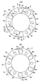
FIG. 1A is a front view of a magnet generator according to a first embodiment of the present invention, FIG. 1B is a cross-sectional view taken along line IB-IB of FIG. 1A, and FIG. It is sectional drawing near a cooling air introduction part.
2A is a front view of an annular plate attached to a rotor yoke for providing a cooling air introduction unit in the embodiment of FIG. 1, and FIG. 2B is a rear view of the annular plate.
FIG. 3A is a front view of a magnet generator according to a second embodiment of the present invention, FIG. 3B is a cross-sectional view taken along the line IIIB-IIIB of FIG. 3A, and FIG. It is sectional drawing of a current plate.
FIG. 4A is a front view of a magnet generator according to a third embodiment of the present invention, FIG. 4B is a cross-sectional view taken along line IVB-IVB of FIG. It is sectional drawing of a current plate.
5A is a front view of a conventional magnet generator, FIG. 5B is a cross-sectional view taken along line VB-VB of FIG. 5A, and FIG. is there.
[Explanation of symbols]
DESCRIPTION OF SYMBOLS 1 ... Rotor yoke, 1a ... Peripheral wall part, 1b ... Bottom wall part, 1d ... Vent hole, 2 ... Permanent magnet, 3 ... Magnet rotor, 4 ... Armature, 5 ... Armature core, 6 ... Armature coil, 8: annular plate, 8a: through hole, 9: cooling air introduction part, 9a: open end, 9b: side wall part, 9c: wing part.
Claims (9)
前記回転子ヨークの底壁部の複数の通気孔の少なくとも一部に対して中空の冷却風導入部が設けられ、
前記冷却風導入部は、前記回転子ヨークの周壁部の開口方向と反対側に膨出した状態で対応する通気孔の少なくとも一部を前記回転子ヨークの外側から覆うように形成され、
前記冷却風導入部は、一端が対応する通気孔を通して前記回転子ヨークの内側に連通させられた冷却風導入通路をその内側に有するとともに、該冷却風導入通路の他端を前記磁石回転子の回転方向の前方側に開口させる開口端を有し、
前記回転子ヨークの外周側に位置する前記冷却風導入部の側壁部は、前記通気孔の近傍から前記回転子ヨークの外周部に向けて斜めに延びて前記開口端に至るように設けられ、
前記冷却風導入部の開口端は、前記回転子ヨークの底壁部の中心と対応する前記通気孔の中心とを結ぶ直線及び前記回転子ヨークの中心軸線の双方を含む基準平面と直交する方向に対して前記回転子ヨークの内径側に傾いた方向に向くように設けられ、
前記冷却風導入部の前記開口端側での前記冷却風導入通路の断面積が、前記基準平面に沿った前記冷却風導入通路の断面積よりも大きくなるように構成されていること、
を特徴とする磁石発電機。A plurality of ventilation holes formed to have a substantially cup-like shape having a peripheral wall portion and a bottom wall portion and penetrating the bottom wall portion are provided so as to be arranged along the outer peripheral portion of the bottom wall portion. In a magnet generator having a magnet rotor having a rotor yoke and a permanent magnet attached to the inner periphery of a peripheral wall of the rotor yoke, and an armature disposed inside the magnet rotor,
A hollow cooling air introduction unit is provided for at least a part of the plurality of ventilation holes in the bottom wall of the rotor yoke,
The cooling air introduction portion is formed so as to cover at least a part of the corresponding ventilation hole from the outside of the rotor yoke in a state where the cooling air introduction portion swells in a direction opposite to the opening direction of the peripheral wall portion of the rotor yoke,
The cooling air introduction portion has a cooling air introduction passage inside one end of which is communicated with the inside of the rotor yoke through a corresponding ventilation hole, and the other end of the cooling air introduction passage has the other end of the magnet rotor. It has an opening end that opens to the front side in the rotation direction,
A side wall portion of the cooling air introduction portion located on an outer peripheral side of the rotor yoke is provided so as to extend obliquely from a vicinity of the ventilation hole toward an outer peripheral portion of the rotor yoke and reach the opening end,
The opening end of the cooling air introduction portion is a direction orthogonal to a reference plane including both a straight line connecting the center of the bottom wall of the rotor yoke and the center of the corresponding ventilation hole and the center axis of the rotor yoke. Is provided so as to face a direction inclined toward the inner diameter side of the rotor yoke,
A cross-sectional area of the cooling air introduction passage at the opening end side of the cooling air introduction portion is configured to be larger than a cross-sectional area of the cooling air introduction passage along the reference plane.
A magnet generator.
Priority Applications (2)
| Application Number | Priority Date | Filing Date | Title |
|---|---|---|---|
| JP2003047595A JP2004260902A (en) | 2003-02-25 | 2003-02-25 | Magnetogenerator |
| US10/770,954 US6815849B2 (en) | 2003-02-25 | 2004-02-03 | Magneto generator |
Applications Claiming Priority (1)
| Application Number | Priority Date | Filing Date | Title |
|---|---|---|---|
| JP2003047595A JP2004260902A (en) | 2003-02-25 | 2003-02-25 | Magnetogenerator |
Publications (1)
| Publication Number | Publication Date |
|---|---|
| JP2004260902A true JP2004260902A (en) | 2004-09-16 |
Family
ID=32866575
Family Applications (1)
| Application Number | Title | Priority Date | Filing Date |
|---|---|---|---|
| JP2003047595A Pending JP2004260902A (en) | 2003-02-25 | 2003-02-25 | Magnetogenerator |
Country Status (2)
| Country | Link |
|---|---|
| US (1) | US6815849B2 (en) |
| JP (1) | JP2004260902A (en) |
Cited By (4)
| Publication number | Priority date | Publication date | Assignee | Title |
|---|---|---|---|---|
| JP2007028876A (en) * | 2005-07-21 | 2007-02-01 | Kokusan Denki Co Ltd | Magnet generator |
| JP2008245462A (en) * | 2007-03-28 | 2008-10-09 | Honda Motor Co Ltd | Outer rotor generator |
| JP2011147337A (en) * | 2010-01-15 | 2011-07-28 | Gate Srl | Rotor for electric motor |
| WO2017179713A1 (en) * | 2016-04-15 | 2017-10-19 | 株式会社デンソー | Rotary electric machine |
Families Citing this family (34)
| Publication number | Priority date | Publication date | Assignee | Title |
|---|---|---|---|---|
| US20040227416A1 (en) * | 2002-05-07 | 2004-11-18 | Shih-Ming Huang | Heat-dissipated mechanism for outer-rotor type brushless DC fan motor |
| WO2005124972A1 (en) * | 2004-06-21 | 2005-12-29 | Mitsubishi Denki Kabushiki Kaisha | Totally-enclosed fancooled motor |
| US20070152521A1 (en) * | 2004-06-24 | 2007-07-05 | Lg Electronics, Inc | Motor of washing machine |
| US7282823B2 (en) * | 2004-10-29 | 2007-10-16 | Emerson Electric Co. | Self-cooling electric machine |
| US7078834B2 (en) * | 2004-12-02 | 2006-07-18 | Asia Vital Component Co., Ltd. | Rotor device capable of dissipating heat |
| KR101092319B1 (en) * | 2004-12-03 | 2011-12-09 | 주식회사 동서전자 | Rotor of outter rotor motor for drum type washing machine |
| US7034417B1 (en) * | 2004-12-20 | 2006-04-25 | Asia Vital Component Co., Ltd. | Rotor assembly capable of dissipating heat |
| JP4450208B2 (en) * | 2005-01-19 | 2010-04-14 | 三菱自動車工業株式会社 | In-wheel motor |
| US7122924B2 (en) * | 2005-02-14 | 2006-10-17 | Asia Vital Component Co., Ltd. | Rotor device capable of forcing heat dissipation |
| US7898125B2 (en) * | 2005-05-25 | 2011-03-01 | Mitsuba Corporation | Electric motor and method of producing electric motor |
| CN100594304C (en) * | 2005-06-09 | 2010-03-17 | 台达电子工业股份有限公司 | Forced heat dissipation structure of the motor |
| JP2007037353A (en) * | 2005-07-29 | 2007-02-08 | Mitsubishi Electric Corp | Magnet generator |
| JP2007135379A (en) * | 2005-11-14 | 2007-05-31 | Mitsubishi Electric Corp | Magnet generator |
| TWI327457B (en) * | 2006-03-03 | 2010-07-11 | Delta Electronics Inc | Fan, motor and impeller thereof |
| JP2008154391A (en) * | 2006-12-19 | 2008-07-03 | Mitsubishi Electric Corp | Magnet generator |
| US7994665B2 (en) * | 2007-08-31 | 2011-08-09 | Brp-Powertrain Gmbh & Co. Kg | Engine electrical generator cooling device and method |
| JP2009278751A (en) * | 2008-05-14 | 2009-11-26 | Kokusan Denki Co Ltd | Starter generator |
| DE102008050848A1 (en) * | 2008-10-08 | 2010-04-15 | Wobben, Aloys | ring generator |
| US8157524B2 (en) | 2009-12-03 | 2012-04-17 | Robert Bosch Gmbh | Axial flow fan with hub isolation slots |
| US8760016B2 (en) * | 2011-07-29 | 2014-06-24 | Exelis Inc. | Electric machine with enhanced cooling |
| US9022754B2 (en) * | 2012-01-04 | 2015-05-05 | Asia Vital Components Co., Ltd. | Fan impeller structure |
| US9973049B2 (en) | 2013-03-15 | 2018-05-15 | Techtronic Industries Co. Ltd. | Electric motor |
| US9680351B2 (en) | 2013-03-15 | 2017-06-13 | Ingersoll-Rand Company | Electrical machine having cooling features |
| US9653967B2 (en) | 2013-03-15 | 2017-05-16 | Techtronic Power Tools Technology Limited | Cooling arrangement for an electric motor |
| JP6372650B2 (en) * | 2014-04-11 | 2018-08-15 | 日本電産株式会社 | Self-cooling motor |
| CN104242553B (en) * | 2014-09-25 | 2017-02-15 | 苏州圆能动力科技有限公司 | Fan assembly structure for generator |
| CN109565232B (en) * | 2016-08-05 | 2021-02-05 | 日本电产株式会社 | motor |
| WO2018173104A1 (en) * | 2017-03-21 | 2018-09-27 | 三菱電機株式会社 | Electric motor and air blowing device |
| CN111971879B (en) * | 2018-03-27 | 2023-05-16 | 电装多利牡株式会社 | Rotary electric machine for internal combustion engine and rotor thereof |
| DE102019107740A1 (en) * | 2019-03-26 | 2020-10-01 | Schaeffler Technologies AG & Co. KG | Electric wheel drive unit for driving a wheel of a motor vehicle |
| CN111156172B (en) * | 2019-12-26 | 2022-06-14 | 珠海格力节能环保制冷技术研究中心有限公司 | Rotor subassembly and rotary compressor |
| WO2021168680A1 (en) * | 2020-02-26 | 2021-09-02 | 威刚科技股份有限公司 | Rotary motor and rotor assembly thereof |
| CN113315287B (en) * | 2020-02-26 | 2023-01-06 | 威刚科技股份有限公司 | Rotating electrical machines and their rotor assemblies |
| SE546445C2 (en) * | 2021-04-28 | 2024-11-05 | Scania Cv Ab | An electric rotating machine with a fluid-guiding member for removing fluid from the rotor compartment |
Family Cites Families (12)
| Publication number | Priority date | Publication date | Assignee | Title |
|---|---|---|---|---|
| JPS5935548A (en) * | 1982-08-18 | 1984-02-27 | Hitachi Ltd | Magnet generator for internal combustion engine |
| GB8603590D0 (en) * | 1986-02-13 | 1986-03-19 | Lucas Ind Plc | Dynamo electric machines |
| JP3038781B2 (en) | 1989-04-21 | 2000-05-08 | 日本電気株式会社 | Memory access control circuit |
| JPH0338781A (en) | 1989-07-05 | 1991-02-19 | Nec Corp | Pattern recognizing device |
| JPH0691718B2 (en) * | 1990-06-01 | 1994-11-14 | 株式会社三ツ葉電機製作所 | Magnet generator cooling fan and method of manufacturing the same |
| IT1240997B (en) * | 1990-10-30 | 1993-12-27 | Magneti Marelli Spa | MOTOR FAN, PARTICULARLY FOR MOTOR VEHICLES |
| JPH0691718A (en) | 1992-09-14 | 1994-04-05 | Bridgestone Corp | Method and apparatus for molding and cutting annular member |
| DE19724920A1 (en) * | 1997-06-12 | 1998-12-17 | Wittur Aufzugteile Gmbh & Co | Drive unit for a hoist |
| JP3494056B2 (en) * | 1999-01-25 | 2004-02-03 | 国産電機株式会社 | Outer rotor type magnet generator |
| IT1308475B1 (en) * | 1999-05-07 | 2001-12-17 | Gate Spa | FAN MOTOR, IN PARTICULAR FOR A HEAT EXCHANGER OF A VEHICLE |
| JP2002136080A (en) * | 2000-10-20 | 2002-05-10 | Kokusan Denki Co Ltd | Rotor for magnet generator |
| AU2002300436B2 (en) * | 2002-02-08 | 2005-01-27 | Lg Electronics Inc. | Outer rotor type induction motor |
-
2003
- 2003-02-25 JP JP2003047595A patent/JP2004260902A/en active Pending
-
2004
- 2004-02-03 US US10/770,954 patent/US6815849B2/en not_active Expired - Fee Related
Cited By (5)
| Publication number | Priority date | Publication date | Assignee | Title |
|---|---|---|---|---|
| JP2007028876A (en) * | 2005-07-21 | 2007-02-01 | Kokusan Denki Co Ltd | Magnet generator |
| JP2008245462A (en) * | 2007-03-28 | 2008-10-09 | Honda Motor Co Ltd | Outer rotor generator |
| JP2011147337A (en) * | 2010-01-15 | 2011-07-28 | Gate Srl | Rotor for electric motor |
| WO2017179713A1 (en) * | 2016-04-15 | 2017-10-19 | 株式会社デンソー | Rotary electric machine |
| JP2017192273A (en) * | 2016-04-15 | 2017-10-19 | 株式会社デンソー | Rotating electric machine |
Also Published As
| Publication number | Publication date |
|---|---|
| US6815849B2 (en) | 2004-11-09 |
| US20040164628A1 (en) | 2004-08-26 |
Similar Documents
| Publication | Publication Date | Title |
|---|---|---|
| JP2004260902A (en) | Magnetogenerator | |
| US5561334A (en) | Rotary electric machine with increased cooling capacity | |
| US9621010B2 (en) | Rotating electrical machine | |
| US5021696A (en) | Cooling fan with reduced noise for variable speed machinery | |
| JP4797779B2 (en) | AC generator for vehicles | |
| US8294309B2 (en) | Electrical rotating machine | |
| JP2000333409A (en) | Induction motor | |
| JPWO2013054811A1 (en) | Rotating electric machine | |
| KR20010031756A (en) | Alternating current generator for vehicles | |
| CN102934328A (en) | Alternator with biaxial airflow | |
| WO2018051589A1 (en) | Electric blower | |
| JP2006217748A (en) | Fan motor | |
| JP3294497B2 (en) | Alternator | |
| JPH10225050A (en) | Crankshaft direct-coupled generator | |
| JP2004274907A (en) | Magnet generator with cover | |
| CN107959382A (en) | generator for internal combustion engine | |
| JPH09172752A (en) | AC generator | |
| JP4111162B2 (en) | AC generator for vehicles | |
| JP2004040935A (en) | Fan motor arrangement | |
| JP4755177B2 (en) | Rotating electrical machinery for automobiles | |
| JPS6020748A (en) | Ac generator for vehicle | |
| JP2013223291A (en) | Rotor of rotary electric machine | |
| CN102097893B (en) | Cooling structure of alternator flywheel | |
| JP2006180617A (en) | Fan motor | |
| JP2001263295A (en) | Centrifugal air blower |
Legal Events
| Date | Code | Title | Description |
|---|---|---|---|
| A621 | Written request for application examination |
Free format text: JAPANESE INTERMEDIATE CODE: A621 Effective date: 20060203 |
|
| A977 | Report on retrieval |
Free format text: JAPANESE INTERMEDIATE CODE: A971007 Effective date: 20081120 |
|
| A131 | Notification of reasons for refusal |
Free format text: JAPANESE INTERMEDIATE CODE: A131 Effective date: 20081202 |
|
| A02 | Decision of refusal |
Free format text: JAPANESE INTERMEDIATE CODE: A02 Effective date: 20090401 |