JP2004263295A - Alloyed hot-dip galvanized steel sheet excellent in plating adhesion and method for producing the same - Google Patents
Alloyed hot-dip galvanized steel sheet excellent in plating adhesion and method for producing the same Download PDFInfo
- Publication number
- JP2004263295A JP2004263295A JP2004013269A JP2004013269A JP2004263295A JP 2004263295 A JP2004263295 A JP 2004263295A JP 2004013269 A JP2004013269 A JP 2004013269A JP 2004013269 A JP2004013269 A JP 2004013269A JP 2004263295 A JP2004263295 A JP 2004263295A
- Authority
- JP
- Japan
- Prior art keywords
- steel sheet
- less
- plating
- dip galvanized
- alloyed hot
- Prior art date
- Legal status (The legal status is an assumption and is not a legal conclusion. Google has not performed a legal analysis and makes no representation as to the accuracy of the status listed.)
- Granted
Links
Images




Classifications
-
- C—CHEMISTRY; METALLURGY
- C23—COATING METALLIC MATERIAL; COATING MATERIAL WITH METALLIC MATERIAL; CHEMICAL SURFACE TREATMENT; DIFFUSION TREATMENT OF METALLIC MATERIAL; COATING BY VACUUM EVAPORATION, BY SPUTTERING, BY ION IMPLANTATION OR BY CHEMICAL VAPOUR DEPOSITION, IN GENERAL; INHIBITING CORROSION OF METALLIC MATERIAL OR INCRUSTATION IN GENERAL
- C23C—COATING METALLIC MATERIAL; COATING MATERIAL WITH METALLIC MATERIAL; SURFACE TREATMENT OF METALLIC MATERIAL BY DIFFUSION INTO THE SURFACE, BY CHEMICAL CONVERSION OR SUBSTITUTION; COATING BY VACUUM EVAPORATION, BY SPUTTERING, BY ION IMPLANTATION OR BY CHEMICAL VAPOUR DEPOSITION, IN GENERAL
- C23C2/00—Hot-dipping or immersion processes for applying the coating material in the molten state without affecting the shape; Apparatus therefor
- C23C2/04—Hot-dipping or immersion processes for applying the coating material in the molten state without affecting the shape; Apparatus therefor characterised by the coating material
- C23C2/06—Zinc or cadmium or alloys based thereon
-
- C—CHEMISTRY; METALLURGY
- C22—METALLURGY; FERROUS OR NON-FERROUS ALLOYS; TREATMENT OF ALLOYS OR NON-FERROUS METALS
- C22C—ALLOYS
- C22C38/00—Ferrous alloys, e.g. steel alloys
- C22C38/02—Ferrous alloys, e.g. steel alloys containing silicon
-
- C—CHEMISTRY; METALLURGY
- C22—METALLURGY; FERROUS OR NON-FERROUS ALLOYS; TREATMENT OF ALLOYS OR NON-FERROUS METALS
- C22C—ALLOYS
- C22C38/00—Ferrous alloys, e.g. steel alloys
- C22C38/04—Ferrous alloys, e.g. steel alloys containing manganese
-
- C—CHEMISTRY; METALLURGY
- C22—METALLURGY; FERROUS OR NON-FERROUS ALLOYS; TREATMENT OF ALLOYS OR NON-FERROUS METALS
- C22C—ALLOYS
- C22C38/00—Ferrous alloys, e.g. steel alloys
- C22C38/06—Ferrous alloys, e.g. steel alloys containing aluminium
-
- C—CHEMISTRY; METALLURGY
- C23—COATING METALLIC MATERIAL; COATING MATERIAL WITH METALLIC MATERIAL; CHEMICAL SURFACE TREATMENT; DIFFUSION TREATMENT OF METALLIC MATERIAL; COATING BY VACUUM EVAPORATION, BY SPUTTERING, BY ION IMPLANTATION OR BY CHEMICAL VAPOUR DEPOSITION, IN GENERAL; INHIBITING CORROSION OF METALLIC MATERIAL OR INCRUSTATION IN GENERAL
- C23C—COATING METALLIC MATERIAL; COATING MATERIAL WITH METALLIC MATERIAL; SURFACE TREATMENT OF METALLIC MATERIAL BY DIFFUSION INTO THE SURFACE, BY CHEMICAL CONVERSION OR SUBSTITUTION; COATING BY VACUUM EVAPORATION, BY SPUTTERING, BY ION IMPLANTATION OR BY CHEMICAL VAPOUR DEPOSITION, IN GENERAL
- C23C2/00—Hot-dipping or immersion processes for applying the coating material in the molten state without affecting the shape; Apparatus therefor
- C23C2/26—After-treatment
- C23C2/28—Thermal after-treatment, e.g. treatment in oil bath
-
- C—CHEMISTRY; METALLURGY
- C23—COATING METALLIC MATERIAL; COATING MATERIAL WITH METALLIC MATERIAL; CHEMICAL SURFACE TREATMENT; DIFFUSION TREATMENT OF METALLIC MATERIAL; COATING BY VACUUM EVAPORATION, BY SPUTTERING, BY ION IMPLANTATION OR BY CHEMICAL VAPOUR DEPOSITION, IN GENERAL; INHIBITING CORROSION OF METALLIC MATERIAL OR INCRUSTATION IN GENERAL
- C23C—COATING METALLIC MATERIAL; COATING MATERIAL WITH METALLIC MATERIAL; SURFACE TREATMENT OF METALLIC MATERIAL BY DIFFUSION INTO THE SURFACE, BY CHEMICAL CONVERSION OR SUBSTITUTION; COATING BY VACUUM EVAPORATION, BY SPUTTERING, BY ION IMPLANTATION OR BY CHEMICAL VAPOUR DEPOSITION, IN GENERAL
- C23C2/00—Hot-dipping or immersion processes for applying the coating material in the molten state without affecting the shape; Apparatus therefor
- C23C2/26—After-treatment
- C23C2/28—Thermal after-treatment, e.g. treatment in oil bath
- C23C2/29—Cooling or quenching
-
- C—CHEMISTRY; METALLURGY
- C23—COATING METALLIC MATERIAL; COATING MATERIAL WITH METALLIC MATERIAL; CHEMICAL SURFACE TREATMENT; DIFFUSION TREATMENT OF METALLIC MATERIAL; COATING BY VACUUM EVAPORATION, BY SPUTTERING, BY ION IMPLANTATION OR BY CHEMICAL VAPOUR DEPOSITION, IN GENERAL; INHIBITING CORROSION OF METALLIC MATERIAL OR INCRUSTATION IN GENERAL
- C23C—COATING METALLIC MATERIAL; COATING MATERIAL WITH METALLIC MATERIAL; SURFACE TREATMENT OF METALLIC MATERIAL BY DIFFUSION INTO THE SURFACE, BY CHEMICAL CONVERSION OR SUBSTITUTION; COATING BY VACUUM EVAPORATION, BY SPUTTERING, BY ION IMPLANTATION OR BY CHEMICAL VAPOUR DEPOSITION, IN GENERAL
- C23C2/00—Hot-dipping or immersion processes for applying the coating material in the molten state without affecting the shape; Apparatus therefor
- C23C2/34—Hot-dipping or immersion processes for applying the coating material in the molten state without affecting the shape; Apparatus therefor characterised by the shape of the material to be treated
- C23C2/36—Elongated material
- C23C2/40—Plates; Strips
-
- Y—GENERAL TAGGING OF NEW TECHNOLOGICAL DEVELOPMENTS; GENERAL TAGGING OF CROSS-SECTIONAL TECHNOLOGIES SPANNING OVER SEVERAL SECTIONS OF THE IPC; TECHNICAL SUBJECTS COVERED BY FORMER USPC CROSS-REFERENCE ART COLLECTIONS [XRACs] AND DIGESTS
- Y10—TECHNICAL SUBJECTS COVERED BY FORMER USPC
- Y10T—TECHNICAL SUBJECTS COVERED BY FORMER US CLASSIFICATION
- Y10T428/00—Stock material or miscellaneous articles
- Y10T428/12—All metal or with adjacent metals
- Y10T428/12472—Microscopic interfacial wave or roughness
-
- Y—GENERAL TAGGING OF NEW TECHNOLOGICAL DEVELOPMENTS; GENERAL TAGGING OF CROSS-SECTIONAL TECHNOLOGIES SPANNING OVER SEVERAL SECTIONS OF THE IPC; TECHNICAL SUBJECTS COVERED BY FORMER USPC CROSS-REFERENCE ART COLLECTIONS [XRACs] AND DIGESTS
- Y10—TECHNICAL SUBJECTS COVERED BY FORMER USPC
- Y10T—TECHNICAL SUBJECTS COVERED BY FORMER US CLASSIFICATION
- Y10T428/00—Stock material or miscellaneous articles
- Y10T428/12—All metal or with adjacent metals
- Y10T428/12493—Composite; i.e., plural, adjacent, spatially distinct metal components [e.g., layers, joint, etc.]
- Y10T428/12771—Transition metal-base component
- Y10T428/12785—Group IIB metal-base component
- Y10T428/12792—Zn-base component
- Y10T428/12799—Next to Fe-base component [e.g., galvanized]
Landscapes
- Chemical & Material Sciences (AREA)
- Engineering & Computer Science (AREA)
- Materials Engineering (AREA)
- Mechanical Engineering (AREA)
- Metallurgy (AREA)
- Organic Chemistry (AREA)
- Chemical Kinetics & Catalysis (AREA)
- Physics & Mathematics (AREA)
- Oil, Petroleum & Natural Gas (AREA)
- Thermal Sciences (AREA)
- Coating With Molten Metal (AREA)
- Heat Treatment Of Sheet Steel (AREA)
Abstract
【課題】素材鋼板に対するめっき密着性に優れた合金化溶融亜鉛めっき鋼板およびその製造方法を提供することにある。
【解決手段】本発明の合金化溶融亜鉛めっき鋼板は、合金化溶融亜鉛めっき層と、該合金化溶融亜鉛めっき層が形成される素材鋼板との界面に、0.5μm以下のピッチで10nm以上の深さの凹凸が、界面の長さ5μm当たりに1個以上存在することを特徴とする。
【選択図】図3An object of the present invention is to provide an alloyed hot-dip galvanized steel sheet having excellent plating adhesion to a material steel sheet and a method for producing the same.
An alloyed hot-dip galvanized steel sheet according to the present invention has an alloyed hot-dip galvanized layer and a steel sheet on which the alloyed hot-dip galvanized layer is formed, and has a pitch of 0.5 μm or less at an interface of 10 nm or more. It is characterized in that one or more depth irregularities exist per 5 μm of interface length.
[Selection diagram] FIG.
Description
本発明は、素材鋼板(母材)に対するめっき密着性に優れた合金化溶融亜鉛めっき鋼板およびその製造方法に関する。 The present invention relates to an alloyed hot-dip galvanized steel sheet having excellent plating adhesion to a base steel sheet and a method for producing the same.
近年、自動車、家電、建材等の分野において素材鋼板に防錆性を付与した表面処理鋼板、中でも安価に製造できかつ塗装後の防錆性に優れた合金化溶融亜鉛めっき鋼板が使用されている。特に自動車分野において、素材鋼板の高性能化とともに軽量化が推進され、素材鋼板の高強度化が求められており、防錆性を兼ね備えた高強度合金化溶融亜鉛めっき鋼板の使用量が増加する傾向にある。 In recent years, in the fields of automobiles, home appliances, building materials, and the like, surface-treated steel sheets provided with rustproofness for material steel sheets, among which alloyed hot-dip galvanized steel sheets that can be manufactured at low cost and have excellent rustproofness after painting have been used. . In the automotive field in particular, as the performance and weight of material steel sheets have been promoted and their weight has been reduced, the strength of the material steel sheets has been required to increase, and the use of high-strength alloyed hot-dip galvanized steel sheets that also have rust prevention will increase. There is a tendency.
しかし、合金化溶融亜鉛めっき鋼板のめっき層と素材鋼板の界面は脆弱なため、例えば金型によるプレス成形時にめっき層が剥離し、剥離しためっき層が金型に付着して製品品質を劣化させるので、金型を清掃する工程が頻繁に必要であったり、副資材による接着接合部でめっき層が剥離して所望の接着強度が得られなかったり、あるいは冬期自動車走行時の石はね等によるチッピングによりめっき層が剥離して、所望の防錆性を維持することができなかったりするという問題があった。 However, since the interface between the coating layer of the alloyed hot-dip galvanized steel sheet and the base steel sheet is weak, for example, the plating layer peels off during press forming with a mold, and the peeled plating layer adheres to the mold and deteriorates the product quality. Therefore, a process of cleaning the mold is frequently required, a desired adhesion strength cannot be obtained due to a peeling of a plating layer at an adhesive joint portion by an auxiliary material, or a stone splash at the time of running a vehicle in winter. There has been a problem that the plating layer is peeled off due to chipping and the desired rust prevention cannot be maintained.
一般的に、溶融亜鉛めっき鋼板は、素材鋼板の表面を前処理工程にて脱脂および/または酸洗して洗浄するか、あるいは前処理工程を省略して予熱炉内で素材鋼板表面の油分を燃焼除去した後、弱酸化性あるいは還元性雰囲気中で予熱し、還元性雰囲気中で再結晶焼鈍される。その後、還元性雰囲気中で素材鋼板を、めっきに適した温度まで冷却して大気に触れることなく微量Al(0.1〜0.2質量%程度)を添加した溶融亜鉛めっき浴中に浸漬した後、めっき厚を調整することで製造される。 Generally, a hot-dip galvanized steel sheet is cleaned by degreasing and / or pickling the surface of the material steel sheet in a pretreatment step, or by omitting the pretreatment step to reduce the oil content on the surface of the material steel sheet in a preheating furnace. After being burned off, it is preheated in a weakly oxidizing or reducing atmosphere and then recrystallized and annealed in a reducing atmosphere. Thereafter, the steel sheet is cooled to a temperature suitable for plating in a reducing atmosphere, and immersed in a hot-dip galvanizing bath containing a small amount of Al (about 0.1 to 0.2% by mass) without contact with the atmosphere. It is manufactured by adjusting.
合金化溶融亜鉛めっき鋼板のめっき層は、FeとZnの相互拡散により形成されるFe−Zn合金相からなる。めっき層と素材鋼板との界面近傍には、Fe含有率の高いFe−Zn合金相が形成し、めっき表層側にいくにしたがってFe含有率の低いFe−Zn合金相が形成される。めっき層と素材鋼板との界面近傍に形成されるFe含有率の高いFe−Zn合金相(例えばΓ相やΓ1相)は硬質で脆いため、過度に厚く形成するとめっき層と素材鋼板の界面の脆弱性を助長する。さらに、合金化溶融亜鉛めっき鋼板のめっき層がFe−Zn合金相であることに起因して、めっき層と素材鋼板の界面におけるめっき層の密着性が悪く、めっき層と鋼板の界面で剥離しやすいという欠点もある。 The plating layer of the alloyed hot-dip galvanized steel sheet is composed of an Fe-Zn alloy phase formed by the interdiffusion of Fe and Zn. An Fe-Zn alloy phase having a high Fe content is formed near the interface between the plating layer and the base steel sheet, and an Fe-Zn alloy phase having a low Fe content is formed toward the plating surface layer. The Fe-Zn alloy phase with a high Fe content (for example, Γ phase and Γ1 phase) formed near the interface between the plating layer and the material steel sheet is hard and brittle. Promote vulnerability. Furthermore, due to the fact that the plating layer of the alloyed hot-dip galvanized steel sheet is an Fe-Zn alloy phase, the adhesion of the plating layer at the interface between the plating layer and the material steel sheet is poor, and the plating layer peels off at the interface between the plating layer and the steel sheet. There is also a disadvantage that it is easy.
従来より、合金化溶融亜鉛めっき鋼板において、素材鋼板に対するめっき密着性を向上させる方法が種々検討されている。例えば、特許文献1では、母材にC:0.006質量%以下の極低炭素IF鋼(Interstitial Free Steel)を使用した場合に鋼中にSi、P等を適量添加することで、母材の結晶粒界にめっき層中のZnの拡散を促進してめっき密着性を向上させる技術が開示されている。しかし、近年の高強度化の要求に応じるためには極低炭素IF鋼では強度不足になり満足する性能を得ることはできない。また、高強度化した鋼板(例えば、母材中にCその他の合金元素を多く含有させ、引張強さを440MPa以上とした鋼板)を用いた場合、前記特許文献1に記載の方法では必ずしも満足するめっき皮膜の密着性が得られないという問題があった。 2. Description of the Related Art Conventionally, various methods for improving the galvanic adhesion to a base steel sheet in an alloyed hot-dip galvanized steel sheet have been studied. For example, in Patent Document 1, when a very low carbon IF steel (Interstitial Free Steel) of C: 0.006% by mass or less is used as a base material, a proper amount of Si, P, or the like is added to the steel to obtain a crystal of the base material. There is disclosed a technique for promoting the diffusion of Zn in a plating layer at a grain boundary to improve plating adhesion. However, in order to meet the recent demand for higher strength, ultra-low carbon IF steels have insufficient strength, and satisfactory performance cannot be obtained. Further, in the case of using a high-strength steel sheet (for example, a steel sheet containing a large amount of C and other alloying elements in the base material and having a tensile strength of 440 MPa or more), the method described in Patent Document 1 is not necessarily satisfactory. There is a problem that the adhesion of the plating film cannot be obtained.
また、特許文献2では、母材にP:0.010〜0.10質量%、Si:0.05〜0.20質量%を含有し、かつSi≧Pを満足するP添加鋼を使用した場合に、めっき皮膜の密着性が向上することが記載されている。しかし、前記P添加鋼以外の鋼板に適用した場合、必ずしも満足するめっき皮膜の密着性が得られないという問題があった。
Further, in
さらに、特許文献3では、母材にC:0.05〜0.25質量%の低炭素鋼を使用し、Si、Alを適量添加した高強度残留オーステナイト鋼の場合に鋼中にTi、Nb等を適量添加して粒界Cを固定することでめっき界面強度を向上させる技術が開示されている。しかし、残留オーステナイト鋼についての技術であり、特許文献3に記載の方法ではその他の残留オーステナイト相を有しない高強度鋼板については必ずしも十分な性能が得られないという問題があった。
Further, in
また、従来から合金化溶融亜鉛めっき鋼板のめっき層と鋼板の界面の密着性を向上する方法について、めっき層と素材鋼板の界面の形状に着目した研究が種々検討されている。例えば、特許文献4および5には、めっき層を除去した後の鋼板表面の粗さが10点平均粗さRzで6.5μm以上とする技術が開示されている。また、特許文献6には、P添加鋼についてめっき被膜除去後の鋼表面の粗さRzを、12≧Rz≧0.0075・Sm+6.7(但し、Rz(μm):10点平均粗さ、Sm(μm):凹凸の平均間隔)とする技術が開示されている。ところが、本発明者らが鋭意研究した結果、めっき密着性に寄与するめっき層と素地鋼板の界面の形状について、従来知見で表記された10点平均粗さRzでは定義し得ない微細凹凸が重要であり、これにより従来にはない著しくめっき密着性に優れた合金化溶融亜鉛めっき鋼板を得ることができるという新たな知見を得た。
In addition, various methods for improving the adhesion between the plating layer of the galvannealed steel sheet and the steel sheet have been studied in the past, focusing on the shape of the interface between the plating layer and the steel sheet. For example,
本発明は、めっき密着性が従来にはない著しく優れた合金化溶融亜鉛めっき鋼板およびその製造方法を提供することを目的とする。 An object of the present invention is to provide an alloyed hot-dip galvanized steel sheet having extremely excellent plating adhesion, which has not been achieved conventionally, and a method for producing the same.
本発明の要旨は以下のとおりである。
(I) 合金化溶融亜鉛めっき層と、該合金化溶融亜鉛めっき層が形成される素材鋼板との界面に、0.5μm以下のピッチで10nm以上の深さの凹凸が、界面の長さ5μm当たりに1個以上存在することを特徴とするめっき密着性に優れた合金化溶融亜鉛めっき鋼板。
The gist of the present invention is as follows.
(I) In the interface between the alloyed hot-dip galvanized layer and the material steel sheet on which the alloyed hot-dip galvanized layer is formed, irregularities having a pitch of 0.5 μm or less and a depth of 10 nm or more per interface length of 5 μm are provided. An alloyed hot-dip galvanized steel sheet having excellent plating adhesion, wherein at least one steel sheet is present in the steel sheet.
(II) 合金化溶融亜鉛めっき層を剥離して観察される素材鋼板の表面形状について、カットオフ波長0.5μmのハイパスフィルタをかけて測定される展開面積比Sdrが2.0%以上であることを特徴とするめっき密着性に優れた合金化溶融亜鉛めっき鋼板。 (II) Regarding the surface shape of the material steel sheet observed by peeling off the galvannealed layer, the developed area ratio Sdr measured with a high-pass filter with a cutoff wavelength of 0.5 μm is 2.0% or more. Galvannealed steel sheet with excellent plating adhesion.
(III) 上記(I)または(II)において、前記素材鋼板が質量%で、C:0.25%以下、Si:0.03〜2.0%およびP:0.005〜0.07%を含有し、かつ、下記(1)式を満足する組成であることを特徴とするめっき密着性に優れた合金化溶融亜鉛めっき鋼板。
記
[C]+[P]≦[Si]・・・・・・・・・・・・(1)
但し、[C]、[P]および[Si]は、それぞれ素材鋼板中のC、PおよびSiの含有量(質量%)を意味する。
(III) In the above (I) or (II), the material steel sheet contains, by mass%, C: 0.25% or less, Si: 0.03 to 2.0% and P: 0.005 to 0.07%, and the following (1) A galvannealed steel sheet having excellent plating adhesion, characterized by having a composition satisfying the formula.
Record
[C] + [P] ≦ [Si] (1)
However, [C], [P] and [Si] mean the contents (% by mass) of C, P and Si in the raw steel sheet, respectively.
(IV) 上記(III)において、前記素材鋼板にめっき層を付着させる直前の段階で、該素材鋼板に含まれるSiが表面に選択酸化されていないように、前記めっき層を付着させる前に素材鋼板が熱処理されてなることを特徴とするめっき密着性に優れた合金化溶融亜鉛めっき鋼板。 (IV) In the above (III), at a stage immediately before the plating layer is attached to the material steel plate, the material contained in the material steel plate is not selectively oxidized on the surface, and the material is deposited before the plating layer is attached. An alloyed hot-dip galvanized steel sheet with excellent plating adhesion, characterized in that the steel sheet is heat-treated.
(V) 上記(III)または(IV)において、前記界面直下の地鉄内にSiの酸化物を有することを特徴とするめっき密着性に優れた合金化溶融亜鉛めっき鋼板。 (V) The alloyed hot-dip galvanized steel sheet according to (III) or (IV) above, which has an oxide of Si in the base iron immediately below the interface, and has excellent plating adhesion.
(VI) 上記(III)、(IV)または(V)において、前記素材鋼板が、さらに質量%で、Mn:5%以下、S:0.01%以下およびAl:0.08%以下を含有する組成であることを特徴とするめっき密着性に優れた合金化溶融亜鉛めっき鋼板。 (VI) In the above (III), (IV) or (V), the material steel sheet is a composition further containing, by mass%, Mn: 5% or less, S: 0.01% or less, and Al: 0.08% or less. An alloyed hot-dip galvanized steel sheet with excellent plating adhesion.
(VII) 上記(III)〜(VI)のいずれか1項において、前記素材鋼板が、さらに質量%で、Ti:0.2%以下、Nb:0.2%以下およびV:0.2%以下の中から選択した1種または2種以上を含有する組成であることを特徴とするめっき密着性に優れた合金化溶融亜鉛めっき鋼板。 (VII) In any one of the above (III) to (VI), the material steel sheet is further selected from Ti: 0.2% or less, Nb: 0.2% or less, and V: 0.2% or less by mass%. An alloyed hot-dip galvanized steel sheet having excellent plating adhesion, characterized in that it has a composition containing one or more kinds.
(VIII) 質量%で、C:0.25%以下、Si:0.03〜2.0%およびP:0.005〜0.07%を含有し、かつ、下記(1)式を満足する組成になる素材鋼板を、鋼中のSiが選択表面酸化されないように熱処理した後、酸素濃度:0.005vol%以下の雰囲気中でめっき温度まで冷却し、該素材鋼板を溶融亜鉛めっき浴に浸漬してめっき層を形成させ、引き続いて20℃/s以上の昇温速度で460〜600℃の温度範囲に加熱し、この加熱温度範囲で保持してめっき層の合金化処理を施すことを特徴とするめっき密着性に優れた合金化溶融亜鉛めっき鋼板の製造方法。
記
[C]+[P]≦[Si]・・・・・・・・・・・・(1)
但し、[C]、[P]および[Si]は、それぞれ素材鋼板中のC、PおよびSiの含有量(質量%)を意味する。
(VIII) A steel sheet containing, by mass%, C: 0.25% or less, Si: 0.03 to 2.0% and P: 0.005 to 0.07% and having a composition satisfying the following formula (1): After heat treatment so that Si is not selectively oxidized on the surface, it is cooled to a plating temperature in an atmosphere having an oxygen concentration of 0.005 vol% or less, and the material steel sheet is immersed in a hot-dip galvanizing bath to form a plating layer. Alloying with excellent plating adhesion characterized by heating to a temperature range of 460 to 600 ° C at a rate of temperature rise of at least ℃ / s, and maintaining the heating temperature range for alloying of the plating layer. Manufacturing method of galvanized steel sheet.
Record
[C] + [P] ≦ [Si] (1)
However, [C], [P] and [Si] mean the contents (% by mass) of C, P and Si in the raw steel sheet, respectively.
(IX) 上記(VIII)において、前記素材鋼板が、さらに質量%で、Mn:5%以下、S:0.01%以下およびAl:0.08%以下を含有する組成であることを特徴とするめっき密着性に優れた合金化溶融亜鉛めっき鋼板の製造方法。 (IX) In the above (VIII), the material steel sheet further has a composition containing, by mass%, Mn: 5% or less, S: 0.01% or less, and Al: 0.08% or less. Method for producing excellent galvannealed steel sheet.
(X) 上記(VIII)または(IX)において、前記素材鋼板が、さらに質量%で、Ti:0.2%以下、Nb:0.2%以下およびV:0.2%以下の中から選択した1種または2種以上を含有する組成であり、さらに前記昇温速度と素材鋼板中のSi含有量が下記(2)式を満足することを特徴とするめっき密着性に優れた合金化溶融亜鉛めっき鋼板の製造方法。
記
ST≧3.25/[Si] ・・・・・(2)
但し、式中のSTは昇温速度(℃/s)であり、[Si]は鋼板中のSi含有量(質量%)である。
(X) In the above (VIII) or (IX), the material steel sheet is further one or two kinds selected from Ti: 0.2% or less, Nb: 0.2% or less, and V: 0.2% or less by mass%. A method for producing a galvannealed steel sheet having excellent plating adhesion, characterized by satisfying the following formula (2), wherein the composition contains the above, and the Si content in the steel sheet further satisfies the following formula (2): .
Record
ST ≧ 3.25 / [Si] ・ ・ ・ ・ ・ (2)
Here, ST in the formula is a heating rate (° C./s), and [Si] is the Si content (% by mass) in the steel sheet.
本発明の合金化溶融亜鉛めっき鋼板は、めっき層と素材鋼板との界面でのめっき密着性が従来にはない著しく優れた合金化溶融亜鉛めっき鋼板であり、自動車、家電、建材等の分野において、加工時のめっき層の剥離という問題が無く、加工後の外観が良好で、かつ充分な防錆性を維持することができる。従って、あらゆる形状の部品に対して高強度化や軽量化を達成することができるという産業上極めて有用な効果をもたらすことができる。 The alloyed hot-dip galvanized steel sheet of the present invention is an alloyed hot-dip galvanized steel sheet having extremely excellent plating adhesion at the interface between the coating layer and the material steel sheet, which has never been seen before, and is used in the fields of automobiles, home appliances, building materials, and the like. There is no problem of peeling of the plating layer during processing, the appearance after processing is good, and sufficient rust prevention can be maintained. Therefore, it is possible to bring about an industrially useful effect that high strength and light weight can be achieved for components of all shapes.
以下、本発明について詳細に説明する。
第1の本発明は、合金化溶融亜鉛めっき層と、該合金化溶融亜鉛めっき層が形成される素材鋼板との界面に、0.5μm以下のピッチで10nm以上の深さの凹凸が、界面の長さ5μm当たりに1個以上存在するめっき密着性に優れた合金化溶融亜鉛めっき鋼板である。
Hereinafter, the present invention will be described in detail.
The first aspect of the present invention is that an unevenness having a pitch of 0.5 μm or less and a depth of 10 nm or more is formed at the interface between the alloyed hot-dip galvanized layer and the material steel sheet on which the alloyed hot-dip galvanized layer is formed. It is an alloyed hot-dip galvanized steel sheet having one or more per 5 μm length and excellent in plating adhesion.
本発明者らが鋭意研究した結果、めっき層と鋼板界面に連続した微細な凹凸部を形成することで、アンカー効果によりめっき層と素材鋼板との界面の密着性が著しく向上することを見出した。 The present inventors have conducted intensive research and found that by forming continuous fine irregularities at the interface between the plating layer and the steel sheet, the adhesion at the interface between the plating layer and the material steel sheet is significantly improved by the anchor effect. .
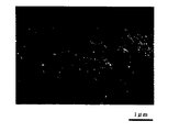
図1および図2は、本発明の一実施例であるめっき層と素材鋼板との界面の連続した凹凸部を示す走査型電子顕微鏡(SEM)で観察した時のSEM写真である。図1は、合金化溶融亜鉛めっき層をアルカリ溶液中で超音波を付与して溶解除去し、めっき層と素材鋼板との界面の素材鋼板表面を露出させて走査型電子顕微鏡で観察したときの表面SEM写真である。図2は、合金化溶融亜鉛めっき鋼板の断面を研磨し、0.1質量%ナイタール液でエッチングした後、走査型電子顕微鏡で観察したときの断面SEM写真である。該凹凸部のピッチは、細かいほど、また凹凸深さは深いほど好ましい。そして、本発明者らは、めっき密着性とめっき界面の凹凸状態との相関について検討した結果、0.5μm以下のピッチで存在する深さ10nm以上の凹凸の存在割合が、めっき層の密着強度と非常に相関があることがわかった。めっき層と素材鋼板との界面の凹凸部は、めっき層の断面を走査型電子顕微鏡(SEM)観察あるいは透過型電子顕微鏡(TEM)観察することで、ピッチおよび深さを測定することができ、以下に測定方法を示す。 FIG. 1 and FIG. 2 are SEM photographs observed with a scanning electron microscope (SEM) showing continuous irregularities at the interface between a plating layer and a material steel sheet according to one embodiment of the present invention. FIG. 1 shows the results when the alloyed hot-dip galvanized layer was dissolved and removed by applying ultrasonic waves in an alkaline solution, and the surface of the material steel sheet at the interface between the plating layer and the material steel sheet was exposed and observed with a scanning electron microscope. It is a surface SEM photograph. FIG. 2 is a cross-sectional SEM photograph when the cross section of the galvannealed steel sheet is polished, etched with a 0.1% by mass nital solution, and then observed with a scanning electron microscope. The finer the pitch of the concave and convex portions and the deeper the concave and convex depth, the better. Then, the present inventors examined the correlation between the plating adhesion and the unevenness state of the plating interface, and found that the proportion of unevenness having a depth of 10 nm or more present at a pitch of 0.5 μm or less was determined as the adhesion strength of the plating layer and the It turned out to be very correlated. The unevenness at the interface between the plating layer and the material steel sheet can be measured for pitch and depth by observing the cross section of the plating layer with a scanning electron microscope (SEM) or a transmission electron microscope (TEM). The measurement method is described below.
ピッチおよび深さの測定は、図3に示すように、前記断面観察により確認できる界面の凹凸曲線1を用い、この凹凸曲線1において、ある基準長さL(例えば0.5μm)内で、高さが最も低い位置にある谷2と、この谷2の両側でそれぞれ高さが最も高い位置にある2つの山3、4とを見つけ出し、これら2つの山3、4間を長さ方向に測定した直線距離をピッチPとし、前記2つの山3、4のうち低い方の山3と谷2の間を高さ方向に測定した直線距離を深さDとして行うこととする。この測定方法を用い、基準長さL(例えば0.5μm)の中で深さDが10nm以上であれば、0.5μm以下のピッチPで10nm以上の深さDの微細な凹凸を有することとなる。
As shown in FIG. 3, the measurement of the pitch and the depth uses the unevenness curve 1 of the interface which can be confirmed by the cross-sectional observation, and the height of the unevenness curve 1 within a certain reference length L (for example, 0.5 μm). Is located at the lowest position and two
但し、本発明では、0.5μm以下のピッチで10nm以上の深さDの凹凸が、界面の長さ(ここで界面長さとは厚さ方向断面において界面上の2点間の直線距離をいう。)5μm当たりに1個以上存在する必要がある。この割合で存在しないと、めっき密着性の向上に寄与しないからである。この凹凸の測定方法は、以下に説明するようにして行なう。すなわち、10μm長さのめっき断面を基準長さL(0.5μm)ずつ分割して20視野観察し(各視野は少なくとも倍率5000倍以上で測定するものとする。)、そのうち、上述の0.5μm以下のピッチPで10nm以上の深さDの微細な凹凸を有する視野を数える。これを任意のめっき断面について5回行い、全視野数(20×5=100)に対する前記微細な凹凸を有する視野数の百分率を、微細な凹凸の占める割合とし、この割合が10%以上である場合を、上記の条件を満たすものとする。 However, in the present invention, the unevenness having a pitch D of 0.5 μm or less and a depth D of 10 nm or more corresponds to the length of the interface (the interface length refers to a linear distance between two points on the interface in a cross section in the thickness direction). ) There must be at least one per 5 μm. If it does not exist at this ratio, it does not contribute to improvement in plating adhesion. The method of measuring the unevenness is performed as described below. That is, a plating section having a length of 10 μm is divided into reference lengths L (0.5 μm) and observed in 20 visual fields (each visual field is measured at a magnification of at least 5000 times). The field of view having fine irregularities with a depth D of 10 nm or more is counted at the pitch P. This is performed five times for an arbitrary plating cross section, and the percentage of the number of the visual fields having the fine irregularities with respect to the total number of visual fields (20 × 5 = 100) is defined as the ratio of the fine irregularities, and this ratio is 10% or more. The case shall satisfy the above conditions.
図4に、このようにして、測定した上記の微細な凹凸が占める割合とめっき層の密着強度との関係を示す。図4から、微細な凹凸の占める割合が10%以上であると、めっき層の密着強度が高い値を示すことがわかる。ここで、めっき層の密着強度は、後述の実施例(のめっき密着性1の評価)に記載した方法で引張試験を行い、引張強度を接着面積で除して求めた値である。 FIG. 4 shows the relationship between the ratio occupied by the fine irregularities thus measured and the adhesion strength of the plating layer. FIG. 4 shows that when the proportion of the fine unevenness is 10% or more, the adhesion strength of the plating layer shows a high value. Here, the adhesion strength of the plating layer is a value obtained by performing a tensile test by the method described in the following Example (evaluation of plating adhesion 1) and dividing the tensile strength by the adhesion area.
以上のことから、本発明では、合金化溶融亜鉛めっき層と素材鋼板との界面に、0.5μm以下のピッチで10nm以上の深さの凹凸が、界面の長さ5μm当たりに1個以上存在することを必要とする。
なお、図1に示したように凹凸の形成には方向性があるが、最も凹凸が密に存在する方向の断面について、この条件を満足すればよい。
From the above, in the present invention, at the interface between the alloyed hot-dip galvanized layer and the base steel sheet, one or more irregularities having a pitch of 0.5 μm or less and a depth of 10 nm or more exist per 5 μm of the interface length. Need that.
As shown in FIG. 1, the formation of the unevenness has directionality, but it is sufficient that this condition is satisfied for the cross section in the direction where the unevenness exists most densely.
次に、第2の本発明について説明する。
第2の本発明は、合金化溶融亜鉛めっき層を剥離して観察される素材鋼板の表面形状について、カットオフ波長0.5μmのハイパスフィルタをかけて測定される展開面積比Sdrが2.0以上であることを特徴とするめっき密着性に優れた合金化溶融亜鉛めっき鋼板である。
Next, the second invention will be described.
In the second aspect of the present invention, the developed area ratio Sdr, which is measured by applying a high-pass filter having a cutoff wavelength of 0.5 μm, to the surface shape of the material steel sheet observed by peeling the galvannealed layer is 2.0 or more. This is an alloyed hot-dip galvanized steel sheet having excellent plating adhesion.
本発明者らは、上述した図1および図2に示した鋼板界面の連続した凹凸の程度を表面から測定できる指標として、展開面積比Sdrに着目した。展開面積比(Developed interfacial area ratio)は測定領域における凹凸のない平面の面積に対する実際の凹凸のある表面の面積の割合を示したもので、下記の式で表される値である。
展開面積比(Sdr)=(A−B)/B×100 (%)
A:測定領域における実際の凹凸のある界面の表面積
B:測定領域における凹凸のない平面の面積
従って、凹凸が大きく表面積の大きな界面ではSdrは大きな値となる。本発明のめっき界面形状は非常に微小な凹凸であるため定量的評価は困難であった。しかし、良好な界面を現出させ、その高倍率SEM像を得て、上記評価指数を精度よく算出することにより微小凹凸を評価することを考えた。すなわち、合金化溶融亜鉛めっき鋼板のめっき層を除去した後の素材表面を、表面組成の影響が出ないようにAuを数十nmコーティングし、これをエリオニクス社の電子線三次元粗さ解析装置ERA−8800FEを用いて測定し、形状解析を行い、展開面積比Sdrを求めた。形状解析は加速電圧15kVにて行い、10000倍の視野(視野面積:12μm×9μm)を、1200×900点の分解能で取り込み、データ処理を行なった。展開面積比Sdrの値は、任意に選択したエリアを測定し平均して求めた。尚、本装置を用いた高さ方向の校正には、米国の国立研究機関であるNISTにトレーサブルなVLSIスタンダード社の触針式、光学式表面粗さ測定機を対象としたSHS薄膜段差スタンダード(段差18nm、88nm、450nmの3種)を用いた。さらに、カットオフ波長を0.5μmとするハイパスフィルタをかけて三次元形状パラメータの算出に供した。この処理は長周期のうねりの影響を除去し、目的とするサイズの凹凸を評価するために重要である。カットオフ波長も評価すべき凹凸のサイズに対して適切に選択する必要がある。種々検討した結果、0.5μm のカットオフ波長によるハイパスフィルタ処理の結果が界面強度との相関や再現性に良好であることがわかったため、この条件で処理を行なった。図10に測定例を示す。図10(a)は密着性不良材(比較例)、図10(b)は密着性良好材(発明例)の3D−SEM像であるが、展開面積比Sdrの値は、比較例が1.7%、発明例が2.5%であり、画像およびSdr値に明瞭な差異が現れている。一方、この画像におけるRaは、比較例が0.00531μm、発明例が0.00547μmであり、一般によく用いられているRaではこの差を数値化できないことがわかり、評価法の有効性も確認できる。
The present inventors paid attention to the development area ratio Sdr as an index capable of measuring the degree of the continuous unevenness at the steel sheet interface shown in FIGS. 1 and 2 from the surface. The developed area ratio (Developed interfacial area ratio) indicates the ratio of the area of the actual surface with irregularities to the area of the flat surface without irregularities in the measurement region, and is a value represented by the following equation.
Development area ratio (Sdr) = (AB) / B × 100 (%)
A: The actual surface area of the interface with irregularities in the measurement area
B: Area of flat surface without irregularities in measurement area Therefore, Sdr takes a large value at an interface with large irregularities and a large surface area. Since the plating interface shape of the present invention is very minute unevenness, it was difficult to quantitatively evaluate it. However, it was considered that a good interface was revealed, a high-magnification SEM image thereof was obtained, and the above-mentioned evaluation index was calculated with high accuracy to evaluate minute irregularities. That is, after removing the plating layer of the alloyed hot-dip galvanized steel sheet, the material surface is coated with Au several tens of nm so as not to be affected by the surface composition, and this is coated with Elionix's electron beam three-dimensional roughness analyzer. Measurement was performed using ERA-8800FE, shape analysis was performed, and the developed area ratio Sdr was determined. The shape analysis was performed at an acceleration voltage of 15 kV, and a 10,000-fold field of view (viewing area: 12 μm × 9 μm) was captured at a resolution of 1200 × 900 points, and data processing was performed. The value of the development area ratio Sdr was obtained by measuring and averaging arbitrarily selected areas. In addition, the height direction calibration using this device is based on the SHS thin film step standard (for the stylus type and optical surface roughness measurement equipment of VLSI Standard, traceable to NIST, a national research institute in the United States). Steps of 18 nm, 88 nm and 450 nm) were used. Further, a high-pass filter having a cutoff wavelength of 0.5 μm was applied to calculate three-dimensional shape parameters. This process is important for removing the influence of long-period undulations and for evaluating unevenness of a target size. The cutoff wavelength also needs to be appropriately selected for the size of the unevenness to be evaluated. As a result of various investigations, it was found that the result of the high-pass filter processing with a cut-off wavelength of 0.5 μm was excellent in the correlation with the interface strength and the reproducibility. FIG. 10 shows a measurement example. FIG. 10 (a) is a 3D-SEM image of a poor adhesion material (comparative example) and FIG. 10 (b) is a 3D-SEM image of a good adhesion material (invention example). % And the invention example is 2.5%, and a clear difference appears between the image and the Sdr value. On the other hand, the Ra in this image is 0.00531 μm in the comparative example and 0.00547 μm in the invention example. It can be seen that this difference cannot be quantified with Ra that is commonly used, and the effectiveness of the evaluation method can be confirmed.
図5は、展開面積比Sdr値と、めっき層と素材鋼板との界面でのめっき界面強度との関係を示すグラフである。図5から、展開面積比Sdr値が2.0%以上である場合に、高い界面強度が得られることがわかる。なお、本発明においては、最も評価に適していると考えられる3次元パラメーターの展開面積比を用いて形状を規定したが、同様のハイパスフィルタ処理を行なったのち、2次元パラメータのRSm(粗さ曲線要素の平均長さ)を用いて評価することも可能である。 FIG. 5 is a graph showing the relationship between the developed area ratio Sdr value and the plating interface strength at the interface between the plating layer and the material steel sheet. FIG. 5 shows that high interface strength can be obtained when the developed area ratio Sdr value is 2.0% or more. In the present invention, the shape is defined using the developed area ratio of the three-dimensional parameter considered to be most suitable for evaluation. However, after performing the same high-pass filter processing, the two-dimensional parameter RSm (roughness) is determined. It is also possible to evaluate using the average length of the curve element).
次に、本発明の素材鋼板として用いて好適な鋼板について説明する。
素材鋼板は質量%で、C:0.25%以下、Si:0.03〜2.0%およびP:0.005〜0.07%を含有し、かつ、下記(1)式を満足する組成であることが好ましい。
記
[C]+[P]≦[Si]・・・・・・・・・・・・(1)
但し、[C]、[P]および[Si]は、それぞれ素材鋼板中のC、PおよびSiの含有量(質量%)を意味する。
Next, a steel sheet suitable for use as the material steel sheet of the present invention will be described.
The base steel sheet preferably contains 0.25% or less by mass of C, 0.03 to 2.0% of Si and 0.005 to 0.07% of P, and has a composition satisfying the following formula (1).
Record
[C] + [P] ≦ [Si] (1)
However, [C], [P] and [Si] mean the contents (% by mass) of C, P and Si in the raw steel sheet, respectively.
ここで、素材鋼板(母材)の鋼中成分C、PおよびSiが上記の範囲であることが好ましいとするのは以下の理由による。なお、以下、元素の含有量(%)は、全て質量%を意味するものとする。 Here, it is preferable that the components C, P, and Si in the steel of the material steel plate (base material) be within the above ranges for the following reasons. Hereinafter, all element contents (%) mean mass%.
C:0.25%以下
C含有量を増加させることで容易に鋼の強度を高めることができ、素材鋼板(母材)の高強度化には必須の元素である。しかし、C含有量が多すぎると、母材の延性、あるいは溶接性が劣化するので、C含有量は0.25%以下とするのが好ましい。また、深絞り用途の鋼板の場合は、Cは極力添加しないことが望ましい。
C: 0.25% or less The strength of steel can be easily increased by increasing the C content, and is an essential element for increasing the strength of a base steel sheet (base material). However, if the C content is too large, the ductility or weldability of the base material deteriorates, so the C content is preferably set to 0.25% or less. In the case of a steel sheet for deep drawing, it is desirable that C is not added as much as possible.
Si:0.03〜2.0%
Siは、鋼の強化元素であると共に、めっき層と素材鋼板との界面に連続した凹凸部を形成させる元素である。詳細は不明だが、Si含有量が0.03%未満では、連続した凹凸部の形成しにくい。一方、Siは合金化反応を遅延させるので合金化の観点では極力添加しないことが望ましく、Si含有量が2.0%超えでは、めっき密着性の向上効果が飽和するとともに、合金化反応を過度に遅延させるという問題が生じやすい。よって、Si含有量は0.03〜2.0%の範囲とすることが好ましい。
Si: 0.03-2.0%
Si is an element that strengthens the steel and also forms a continuous uneven portion at the interface between the plating layer and the material steel sheet. Details are unknown, but if the Si content is less than 0.03%, it is difficult to form continuous uneven portions. On the other hand, since Si delays the alloying reaction, it is desirable not to add Si as much as possible from the viewpoint of alloying. If the Si content exceeds 2.0%, the effect of improving plating adhesion is saturated and the alloying reaction is excessively delayed. The problem of causing Therefore, the Si content is preferably in the range of 0.03 to 2.0%.
P:0.005〜0.07%
Pは、鋼の強化元素である。しかし、著しい結晶粒界偏析元素で、合金化反応を過度に遅延させたり、溶接性を劣化させるので、極力低減することが望ましく、P含有量は0.07%以下が好ましい。しかし、鋼中のP含有量を必要以上に低減させるためには、高純度で高級な電解鉄を使用する必要があり、経済性を損なうという問題があるので、P含有量は0.005%以上であることが好ましい。
また、本発明では、前記素材鋼板中のC、SiおよびPの含有量を上記範囲に限定するとともに、下記(1)式を満足する組成であることが好ましい。
記
[C]+[P]≦[Si]・・・・・・・・・・・・(1)
但し、[C]、[P]および[Si]は、それぞれ素材鋼板中のC、PおよびSiの含有量(質量%)を意味する。
P: 0.005 to 0.07%
P is a strengthening element of steel. However, a remarkable crystal grain boundary segregation element excessively delays the alloying reaction and deteriorates the weldability. Therefore, it is desirable to reduce the P content as much as possible, and the P content is preferably 0.07% or less. However, in order to reduce the P content in the steel more than necessary, it is necessary to use high-purity and high-grade electrolytic iron, and there is a problem of impairing the economy. Therefore, the P content is 0.005% or more. Preferably, there is.
Further, in the present invention, it is preferable that the content of C, Si and P in the material steel sheet is limited to the above range, and the composition satisfy the following formula (1).
Record
[C] + [P] ≦ [Si] (1)
However, [C], [P] and [Si] mean the contents (% by mass) of C, P and Si in the raw steel sheet, respectively.
上記述べたように、鋼中にSi添加することで、めっき層と素材鋼板との界面に連続した凹凸部を形成し、めっき密着性が著しく向上する。しかし、鋼中にSiに加えCやPを複合添加すると、めっき層と素材鋼板との界面の連続した凹凸部の形成を抑制し、めっき密着性の向上を阻害する。上述のようにCおよびPは鋼強化元素であり、高強度化には必須の元素である。つまり、めっき密着性に寄与する連続した凹凸部を形成させるには、CとPの添加量に応じて上記(1)式に示したようにSi添加量も調整する必要がある。[C]+[P]≦[Si]の場合、めっき層と素材鋼板の界面に連続した凹凸部を形成させることが容易となる。 As described above, by adding Si to the steel, a continuous uneven portion is formed at the interface between the plating layer and the base steel sheet, and the plating adhesion is significantly improved. However, when C and P are added to the steel in addition to Si, the formation of continuous irregularities at the interface between the plating layer and the base steel sheet is suppressed, and the improvement in plating adhesion is hindered. As described above, C and P are steel strengthening elements and are essential elements for increasing the strength. That is, in order to form a continuous uneven portion that contributes to plating adhesion, it is necessary to adjust the amount of Si added as shown in the above equation (1) according to the amounts of C and P added. In the case of [C] + [P] ≦ [Si], it is easy to form a continuous uneven portion at the interface between the plating layer and the base steel sheet.
また、C、SiおよびP以外の他の元素が鋼中に含有されていてもかまわない。 Further, elements other than C, Si and P may be contained in the steel.
他の元素としては、素材鋼板に含有される成分としてMn、SおよびAlが挙げられ、これら元素の好適範囲は以下のとおりである。 Other elements include Mn, S and Al as components contained in the raw steel sheet, and preferable ranges of these elements are as follows.
Mn:5%以下
Mnは、鋼の強化元素であり、必要に応じて含有することができる。しかし、Mn含有量が5%を超えると、母材の加工性や経済性を損なうので、Mn含有量は5%以下とすることが好ましい。尚、鋼の強化作用を十分に得るためには、Mn含有量を0.5%以上とすることが好ましい。
Mn: 5% or less
Mn is a strengthening element for steel and can be contained as necessary. However, if the Mn content exceeds 5%, the workability and economy of the base material are impaired, so the Mn content is preferably 5% or less. In order to sufficiently obtain the strengthening effect of steel, the Mn content is preferably set to 0.5% or more.
S:0.01%以下
Sは、鋼中に不可避的に存在する元素であり、S含有量が0.01%よりも多くなると素材鋼板の加工性が低下する傾向がある。よって、S含有量は0.01%以下とすることが好ましい。
S: 0.01% or less S is an element inevitably present in steel, and when the S content is more than 0.01%, the workability of the material steel sheet tends to decrease. Therefore, the S content is preferably set to 0.01% or less.
Al:0.08%以下
Alは、脱酸剤としての働きがあるので、必要に応じて含有することができる。しかし、Al含有量が0.08%超えとしてもその効果は飽和するだけで、製造コストの増加を招くので、Al含有量は0.08%以下とすることが好ましい。なお、脱酸剤としての作用を発現させるには、Al含有量は0.02%以上とすることが好ましい。
Al: 0.08% or less
Since Al has a function as a deoxidizing agent, it can be contained as necessary. However, even if the Al content exceeds 0.08%, the effect is only saturated and the production cost is increased. Therefore, the Al content is preferably set to 0.08% or less. In addition, in order to exhibit the function as a deoxidizing agent, the Al content is preferably set to 0.02% or more.
さらに、鋼の強化元素としてTi、NbおよびVの中から選択した1種または2種以上を含有させてもよい。Ti、NbおよびVは、いずれも鋼中のC、Nと結合して微細な析出物を形成し、素材鋼板を高強度化することができる。ここで、Ti、NbおよびVの各成分を0.2%よりも多く添加すると、加工性が阻害される傾向があるため、Ti、NbおよびVの含有量は、それぞれ0.2%以下とすることが好ましい。 Further, one or more selected from Ti, Nb and V may be contained as a steel strengthening element. All of Ti, Nb and V combine with C and N in the steel to form fine precipitates, and can increase the strength of the material steel sheet. Here, if the respective components of Ti, Nb and V are added in excess of 0.2%, the workability tends to be impaired, so that the contents of Ti, Nb and V are each preferably 0.2% or less. .
また、Ti、NbおよびVの中から選択した1種または2種以上を適量添加すると、固溶Pと結びついて、Fe−(Ti、Nb、V)−Pの微細な析出物を形成し、一部の固溶Pを無害化することができる。その結果、FeとZnの相互拡散反応を過度に遅延させることなく、めっき界面強度を著しく向上させることができる。このような効果を発現させるためには、鋼中のP含有量に応じて下記(3)式を満足するTi、NbおよびVの1種または2種以上を含有させることが好ましい。
[Ti]+[Nb]+[V]≧[P]・・・・・・・・・(3)
但し、[Ti]、[Nb]、[V]および[P]は、それぞれ素材鋼板中のTi、Nb、VおよびPの含有量(質量%)を意味する。
When one or more selected from Ti, Nb and V are added in an appropriate amount, they are combined with solid solution P to form fine precipitates of Fe- (Ti, Nb, V) -P, Some of the solute P can be rendered harmless. As a result, the plating interface strength can be significantly improved without excessively delaying the interdiffusion reaction between Fe and Zn. In order to exhibit such an effect, it is preferable to contain one or more of Ti, Nb and V satisfying the following formula (3) according to the P content in the steel.
[Ti] + [Nb] + [V] ≧ [P] (3)
However, [Ti], [Nb], [V] and [P] mean the contents (% by mass) of Ti, Nb, V and P in the raw steel sheet, respectively.
以上述べた素材鋼板中の成分以外のCr、Mo、Cu、Ni、Ca、B、N、Sb等の成分については、添加の有無に関わらず本発明の効果に何ら寄与するものではないため、必要に応じて添加してもかまわない。それぞれの添加理由と好適範囲は以下のとおりである。 Components such as Cr, Mo, Cu, Ni, Ca, B, N, and Sb other than the components in the material steel plate described above do not contribute to the effect of the present invention regardless of the presence or absence of addition, It may be added as needed. Reasons for addition and preferred ranges are as follows.
Cr:0.5%以下
鋼強化元素であり必要に応じて添加してもよい。但し、めっき性低下、合金化むらを引き起こすので好ましくは0.5%以下が好ましい。
Cr: 0.5% or less This is a steel strengthening element and may be added as necessary. However, it is preferable that the content be 0.5% or less because it causes a decrease in plating property and uneven alloying.
Mo:1.0%以下
鋼強化元素であり必要に応じて添加してもよい。但し、合金化遅延、加工性や経済性を損なうので好ましくは1%以下とする。
Mo: 1.0% or less It is a steel strengthening element and may be added as necessary. However, it is preferably 1% or less because alloying delay, workability and economy are impaired.
Cu:0.5%以下
めっき性改善元素であり、必要に応じて添加してもよい。但し、0.5%超で効果が飽和し、経済性を損なうので好ましくは0.5%以下とする。
Cu: 0.5% or less Plating property improving element, which may be added as necessary. However, if the content exceeds 0.5%, the effect is saturated and the economy is impaired, so the content is preferably set to 0.5% or less.
Ni:0.5%以下
めっき性改善元素であり、必要に応じて添加してもよい。但し、0.5%超で効果が飽和し、経済性を損なうので好ましくは0.5%以下とする。
Ni: 0.5% or less Plating property improving element, which may be added as necessary. However, if the content exceeds 0.5%, the effect is saturated and the economy is impaired, so the content is preferably set to 0.5% or less.
Ca:0.01%以下
脱酸剤であり、必要に応じて含有してもよい。但し、0.01%超で効果が飽和するので0.01%以下が好ましい。
Ca: 0.01% or less It is a deoxidizing agent and may be contained as necessary. However, since the effect is saturated at more than 0.01%, it is preferably 0.01% or less.
B:0.003%以下
粒界強化により二次加工脆性を改善できる。0.003%超は効果が飽和するので、0.003%以下が好適である。
B: 0.003% or less Secondary processing embrittlement can be improved by grain boundary strengthening. If the content exceeds 0.003%, the effect is saturated, so 0.003% or less is preferable.
N:0.01%以下
Nは不純物として混入する。0.01%を超えると、延性が低下するため0.01%以下が好ましい。
N: 0.01% or less N is mixed as an impurity. If it exceeds 0.01%, the ductility decreases, so 0.01% or less is preferable.
Sb:0.05%以下
めっき外観むら改善元素であり必要に応じて添加できる。但し、0.05%超で効果が飽和し、経済性を損なうので好ましくは0.05%以下である。
Sb: 0.05% or less Sb is an element for improving uneven plating appearance and can be added as necessary. However, if the content exceeds 0.05%, the effect is saturated and the economy is impaired, so the content is preferably 0.05% or less.
以上説明した元素以外の残部はFeおよび不可避的不純物からなることが好ましい。 The balance other than the elements described above is preferably made of Fe and inevitable impurities.
また、本発明では、素材鋼板の引張強さは、JIS Z2201に規定された5号試験片を使用し、JIS G 3302に規定された引張試験方法で測定して440MPa以上であることが好ましい。素材鋼板を引張強さが440MPa以上の高張力鋼板とすることで、自動車、家電、建材等の分野において素材の高強度化および/または軽量化の要求を満足し得るからである。 In the present invention, the tensile strength of the base steel sheet is preferably 440 MPa or more as measured by a tensile test method specified in JIS G 3302 using a No. 5 test piece specified in JIS Z2201. This is because by using a high-tensile steel sheet having a tensile strength of 440 MPa or more as the material steel sheet, it is possible to satisfy the demand for higher strength and / or lighter weight of the material in the fields of automobiles, home appliances, building materials, and the like.
次に、合金化溶融亜鉛めっき層と素材鋼板との界面に、本発明の凹凸(0.5μm以下のピッチで10nm以上の深さの凹凸が、界面の長さ5μm当たりに1個以上存在するか、あるいは、合金化溶融亜鉛めっき層を剥離して観察される素材鋼板の表面形状について、カットオフ波長0.5μmのハイパスフィルタをかけて測定される展開面積比Sdrが2.0%以上である凹凸)を形成させるための製造条件について、以下で説明する。 Next, at the interface between the alloyed hot-dip galvanized layer and the base steel sheet, the unevenness of the present invention (whether there is at least one unevenness with a pitch of 0.5 μm or less and a depth of 10 nm or more per 5 μm of the interface length) Or, for the surface shape of the material steel sheet observed by peeling off the galvannealed layer, the unevenness with a developed area ratio Sdr of 2.0% or more measured using a high-pass filter with a cutoff wavelength of 0.5 μm) Manufacturing conditions for the formation will be described below.
本発明の合金化溶融亜鉛めっき鋼板は、例えば上述した成分組成を有する鋼板を素材鋼板として、溶融亜鉛めっきおよびその後の合金化処理を施すことで製造できる。ここで、素材鋼板は、熱延鋼板、冷延鋼板、あるいはこれらを特殊熱処理後の鋼板のいずれでもよく、特に限定するものではない。素材鋼板は、表面を前処理工程にて脱脂および/または酸洗して洗浄するか、あるいは前処理工程を省略して予熱炉内で素材鋼板表面の油分を燃焼除去した後、還元性雰囲気中で750〜900℃程度の焼鈍を施す。これにより、素材鋼板表面のスケールは還元され、その後の溶融亜鉛めっきに適した表面状態となる。ここで、鋼中にSiを添加した素材鋼板の場合、SiはFeにとっては還元性雰囲気であっても選択的に表面酸化される場合があり、表面に濃化して酸化物を形成することがある。表面に選択的に酸化したSi酸化物はめっき処理時の溶融亜鉛との濡れ性を低下させて不めっきを生じさせるので、還元性雰囲気中での選択表面酸化を抑制する必要がある。さらに、前述のように鋼中のSiはめっき層と素材鋼板との界面に微細な凹凸部を形成させる作用を有するが、Siが酸化物として存在してもその効果は発現しないので、還元性雰囲気中での選択表面酸化を実質的に抑制する必要がある。 The alloyed hot-dip galvanized steel sheet of the present invention can be manufactured, for example, by subjecting a steel sheet having the above-described composition to a material steel sheet and performing hot-dip galvanizing and subsequent alloying treatment. Here, the material steel sheet may be any of a hot-rolled steel sheet, a cold-rolled steel sheet, or a steel sheet obtained by subjecting them to special heat treatment, and is not particularly limited. The material steel sheet is cleaned by degreasing and / or pickling the surface in a pretreatment step, or after omitting the pretreatment step and burning off the oil on the surface of the material steel sheet in a preheating furnace, and then reducing the surface in a reducing atmosphere. Anneal at about 750-900 ° C. As a result, the scale on the surface of the material steel sheet is reduced, and the surface state becomes suitable for subsequent hot-dip galvanizing. Here, in the case of a material steel sheet in which Si is added to steel, Si may be selectively oxidized on the surface of Fe even in a reducing atmosphere, and may concentrate on the surface to form an oxide. is there. Since the Si oxide selectively oxidized on the surface lowers the wettability with the molten zinc during the plating treatment and causes non-plating, it is necessary to suppress the selective surface oxidation in a reducing atmosphere. Furthermore, as described above, Si in steel has the effect of forming fine irregularities at the interface between the plating layer and the steel sheet, but the effect is not exhibited even if Si is present as an oxide, It is necessary to substantially suppress selective surface oxidation in an atmosphere.
ここで、Siの選択表面酸化を実質的に抑制するとは、上述の通り、めっき濡れ性を低下させて不めっきを生じさせない状態のことを意味し、不めっきが発生しない状態であれば問題ない。 Here, to substantially suppress selective surface oxidation of Si means, as described above, a state in which plating wettability is reduced and non-plating does not occur, and there is no problem as long as non-plating does not occur. .
鋼中にSiを添加した鋼を用いて還元性雰囲気中で実質的にSiが選択表面酸化されない状態を得る方法としては、特に限定するものではないが、還元性雰囲気中での焼鈍前に弱酸化性雰囲気、例えば1vol%以下の微量酸素を含む不活性ガス雰囲気中で予備加熱処理あるいは加熱昇温処理を行う方法がある。すなわち、弱酸化性雰囲気中で鋼板表面を酸化させて薄い鉄スケールを生成し、次いで還元性雰囲気中で焼鈍して鋼板表面に還元鉄を生成させることで、Siの選択表面酸化を抑制することができる。弱酸化性雰囲気とは、その後の還元性雰囲気中で十分還元処理が行える程度の酸化性雰囲気という意味で、特に限定するものではない。弱酸化性雰囲気としては、例えば、酸素:0.01〜0.5vol%、露点:-20℃〜+20℃を含み、残部が窒素からなり、温度:300〜500℃の雰囲気が挙げられ、また、還元性雰囲気としては、例えば、水素:3〜20vol%を含み、残部が窒素からなり、温度:750〜900℃の雰囲気が挙げられる。 The method of obtaining a state in which Si is not substantially selectively oxidized in a reducing atmosphere using a steel in which Si is added to the steel is not particularly limited, but the weak acid may be used before annealing in the reducing atmosphere. There is a method of performing a preliminary heating treatment or a heating and heating treatment in a oxidizing atmosphere, for example, an inert gas atmosphere containing a trace amount of oxygen of 1 vol% or less. In other words, by oxidizing the steel sheet surface in a weakly oxidizing atmosphere to generate a thin iron scale, and then annealing in a reducing atmosphere to generate reduced iron on the steel sheet surface, thereby suppressing selective surface oxidation of Si. Can be. The weakly oxidizing atmosphere is not particularly limited in the sense that it is an oxidizing atmosphere in which a sufficient reduction treatment can be performed in a subsequent reducing atmosphere. Examples of the weakly oxidizing atmosphere include an atmosphere containing 0.01 to 0.5 vol% oxygen, a dew point of -20 ° C to + 20 ° C, and the balance consisting of nitrogen, and a temperature of 300 to 500 ° C. The atmosphere includes, for example, an atmosphere containing 3 to 20 vol% of hydrogen, the balance being nitrogen, and having a temperature of 750 to 900 ° C.
なお、弱酸化性雰囲気中で鋼板表面を酸化させて薄い鉄スケールを生成し、次いで還元性雰囲気中で焼鈍して鋼板表面に還元鉄を生成させると、弱酸化性雰囲気で生成したFe酸化物は、続く還元性雰囲気中での焼鈍で還元され、Si酸化物は還元性雰囲気中での焼鈍の際にも還元されないので、素材鋼板の表面直下の地鉄内に内部酸化物として残存する。この内部酸化物は、Siが選択表面酸化された酸化物とは区別され、還元性雰囲気中での焼鈍の際にSiが選択表面酸化されることを抑制する作用がある。この内部酸化物は、溶融亜鉛めっき工程およびそれに続く合金化工程後にも残存する。 In addition, when the steel sheet surface is oxidized in a weakly oxidizing atmosphere to produce a thin iron scale, and then annealed in a reducing atmosphere to produce reduced iron on the steel sheet surface, the Fe oxide generated in the weakly oxidizing atmosphere Is reduced by the subsequent annealing in a reducing atmosphere, and the Si oxide is not reduced even in the annealing in the reducing atmosphere, and thus remains as an internal oxide in the base steel immediately below the surface of the base steel sheet. This internal oxide is distinguished from an oxide in which Si is selectively oxidized on the surface, and has an effect of suppressing the selective oxidation of Si in the surface during annealing in a reducing atmosphere. This internal oxide remains after the galvanizing step and the subsequent alloying step.
設備的に弱酸化性雰囲気中での予備加熱処理あるいは加熱昇温処理を行うことができない場合、還元雰囲気中で800〜900℃の比較的高温の一次加熱処理を行なった後、酸洗あるいは研削等の処理により表面酸化物を除去する。次いで、還元雰囲気中で800℃以下の比較的低温の二次加熱処理を行なった後、大気に触れることなくめっき処理を行うことでSiの選択表面酸化を実質的に抑制することができる。上述のように還元雰囲気中で実質的にSiが選択表面酸化されない状態を得る方法としては、特に限定するものではなく、またいずれの方法においても、本発明の効果を妨げるものではない。 If the equipment cannot perform preheating or heating in a weakly oxidizing atmosphere, perform primary heating at a relatively high temperature of 800 to 900 ° C in a reducing atmosphere, and then pickle or grind. And the like to remove surface oxides. Next, after performing a relatively low-temperature secondary heat treatment at 800 ° C. or lower in a reducing atmosphere, the selective oxidation of the surface of Si can be substantially suppressed by performing the plating treatment without being exposed to the air. As described above, a method for obtaining a state in which Si is not substantially selectively oxidized in a reducing atmosphere is not particularly limited, and any method does not hinder the effects of the present invention.
焼鈍後の素材鋼板は、前記還元雰囲気中でめっきに適した温度、好ましくは440〜540℃まで冷却され、大気に触れることなく溶融亜鉛めっき浴中に浸漬し、めっきが施される。このとき、めっき直前の雰囲気を酸素濃度:0.005vol%以下の雰囲気とする。これは特に酸素は、素材鋼板表面の反応性を低下させて、めっき層と素材鋼板との界面の微細凹凸の形成を阻害するからである。酸素以外の残部ガスは微細凹凸の形成に対し、特に影響を及ぼさないので限定されない。例えば、水素:3〜20vol%、残部窒素の雰囲気が挙げられる。また、酸素は溶融亜鉛との濡れ性を低下させ不めっきを誘発するので、この意味からも低い方がよい。 The annealed material steel sheet is cooled in the reducing atmosphere to a temperature suitable for plating, preferably 440 to 540 ° C., immersed in a hot-dip galvanizing bath without being exposed to the air, and plated. At this time, the atmosphere immediately before plating is an atmosphere having an oxygen concentration of 0.005 vol% or less. This is because oxygen particularly lowers the reactivity of the surface of the material steel sheet and hinders the formation of fine irregularities at the interface between the plating layer and the material steel sheet. The remaining gas other than oxygen is not limited because it does not particularly affect the formation of the fine irregularities. For example, an atmosphere of hydrogen: 3 to 20 vol% and the balance of nitrogen can be mentioned. Further, oxygen lowers the wettability with the molten zinc and induces non-plating, and therefore, the lower the oxygen, the better.
溶融亜鉛めっき処理は、従来から行なわれている方法に従って行えばよく、例えばめっき浴温は450〜500℃程度とし、めっき浴中のAl濃度は0.10〜0.15質量%とするのが好適である。但し、鋼中成分によっては上記めっき条件を変更する必要があるが、めっき条件の違いは、本発明の効果に何ら寄与するものではなく、特に限定するものではない。 The hot-dip galvanizing treatment may be performed according to a conventional method. For example, it is preferable that the plating bath temperature is about 450 to 500 ° C. and the Al concentration in the plating bath is 0.10 to 0.15 mass%. However, it is necessary to change the above plating conditions depending on the components in the steel, but the difference in the plating conditions does not contribute to the effect of the present invention at all and is not particularly limited.
めっき後のめっき層の厚さを調整する方法は、特に限定するものではないが、一般的にガスワイピングが使用され、ガスワイピングのガス圧、ワイピングノズルと鋼板との間の距離等により調整される。このとき、めっき層の厚さは、3〜15μmの範囲が好ましい。3μm未満では、防錆性が充分に得られない。一方、15μm超えでは、防錆性の向上効果が飽和するばかりか、加工性や経済性が低下する傾向にあるので好ましくない。 Although the method of adjusting the thickness of the plating layer after plating is not particularly limited, gas wiping is generally used, and the gas pressure of gas wiping, the distance between the wiping nozzle and the steel sheet are adjusted. You. At this time, the thickness of the plating layer is preferably in the range of 3 to 15 μm. If it is less than 3 μm, sufficient rust prevention cannot be obtained. On the other hand, if it exceeds 15 μm, not only the effect of improving rust prevention properties is saturated, but also the workability and economic efficiency tend to decrease, which is not preferable.
めっき厚を調整した後の合金化加熱処理方法は、ガス加熱やインダクション加熱等の方法にて行うことができる。但し、合金化温度までの昇温時の平均昇温速度は20℃/s以上であることが必要である。20℃/s未満の場合、低温域での滞留時間が長く合金化反応の遅延が生じ、めっき層と素材鋼板との界面の微細な凹凸の形成を阻害するからである。 The alloying heat treatment method after adjusting the plating thickness can be performed by a method such as gas heating or induction heating. However, it is necessary that the average heating rate at the time of heating up to the alloying temperature is 20 ° C./s or more. If the temperature is lower than 20 ° C./s, the residence time in the low-temperature region is long, and the alloying reaction is delayed, which hinders the formation of fine irregularities at the interface between the plating layer and the steel sheet.
また、素材鋼板中に、Ti、NbおよびVが上述の範囲で含有されている場合には、合金化処理での加熱時の昇温速度と素材鋼板中のSi含有量が下記(2)式を満足するようにする必要がある。
記
ST≧3.25/[Si]・・・・・(2)
但し、式中のSTは昇温速度(℃/s)であり、[Si]は鋼板中のSi含有量(質量%)である。
Further, when Ti, Nb and V are contained in the above-mentioned range in the base steel sheet, the heating rate during the alloying treatment and the Si content in the base steel sheet are expressed by the following formula (2). Needs to be satisfied.
Record
ST ≧ 3.25 / [Si] ・ ・ ・ ・ ・ ・ ・ (2)
Here, ST in the formula is a heating rate (° C./s), and [Si] is the Si content (% by mass) in the steel sheet.
発明者らの調査によれば、鋼中にTi、NbおよびVが含有されていると、鋼中のSi含有量が低い場合には、合金化処理時の昇温速度を20℃/s以上としても、本発明のめっき層と素材鋼板との界面の微細な凹凸が形成しない場合があり、Si含有量に応じて昇温速度を上昇させる必要があることがわかった。 According to the investigations of the inventors, when Ti, Nb and V are contained in steel, when the Si content in the steel is low, the heating rate during the alloying treatment is set to 20 ° C./s or more. Even in this case, fine irregularities at the interface between the plating layer of the present invention and the base steel sheet may not be formed in some cases, and it has been found that it is necessary to increase the heating rate according to the Si content.
図6は、上述の(3)式を満たす範囲でTi、NbおよびVのうちの1種または2種以上を含有する鋼板について、微細凹凸の面積率に対するSi含有量と昇温速度との影響を示すグラフである。上記(2)式を満たすことにより、微細凹凸の面積率が10%以上となることがわかる。 FIG. 6 shows the effect of the Si content and the heating rate on the area ratio of fine irregularities in a steel sheet containing one or more of Ti, Nb, and V within a range satisfying the above equation (3). FIG. It can be seen that by satisfying the above expression (2), the area ratio of the fine irregularities becomes 10% or more.
合金化処理時間は、特に限定はしないが、めっき層中のFe含有率は8〜13質量%に調整することが好ましい。めっき層中のFe含有率が8質量%未満では、前述したFe−Zn合金相が充分生成されず、めっき表層に軟質なη−Zn相が残存するので、加工性、接着性に支障をきたす場合がある。一方、めっき層中のFe含有率が13質量%超えでは、めっき層と素材鋼板の界面に硬質で脆いFe−Zn合金相(例えばΓ相やΓ1相)が過度に厚く形成し、めっき層と鋼板の界面の脆弱性を助長するので問題である。 The alloying time is not particularly limited, but the Fe content in the plating layer is preferably adjusted to 8 to 13% by mass. If the Fe content in the plating layer is less than 8% by mass, the above-mentioned Fe-Zn alloy phase is not sufficiently generated, and a soft η-Zn phase remains on the plating surface layer, which impairs workability and adhesion. There are cases. On the other hand, if the Fe content in the plating layer exceeds 13% by mass, a hard and brittle Fe-Zn alloy phase (for example, Γ phase or Γ1 phase) is excessively formed at the interface between the plating layer and the material steel sheet, and This is a problem because it promotes the brittleness of the steel sheet interface.
ここで言う「めっき層中のFe含有率」とは、全めっき層に対するめっき層中のFeの質量百分率であり、平均Fe含有率のことである。めっき層中のFe含有率を測定する方法は、例えば、合金化溶融亜鉛めっき層をインヒビター入りの塩酸で溶解させ、ICP(Inductively Coupled Plasma)発光分光分析法で測定することができる。 Here, the “Fe content in the plating layer” is a mass percentage of Fe in the plating layer with respect to all the plating layers, and is an average Fe content. The method of measuring the Fe content in the plating layer can be, for example, by dissolving the alloyed hot-dip galvanized layer with hydrochloric acid containing an inhibitor and measuring it by ICP (Inductively Coupled Plasma) emission spectroscopy.
めっき層中のFe含有率を8〜13質量%に調整する方法は特に限定するものではないが、一般的に合金加熱処理炉内での板温や在炉時間等により調整される。在炉時間は、生産性の観点から短い方が好ましく、具体的には5〜30秒程度で操業される。また、板温は、在炉時間との関係で選択されるが、一般的には460〜600℃で操業される。460℃未満の場合、めっき層中のFe含有率を8〜13質量%に調整するには、長時間の合金化処理を余儀なくされ、鋼板速度を極端に遅くするかあるいは長大な合金化処理炉が必要になる。そのため、生産性の低下あるいは膨大な設備費が必要になるという問題があることから、460℃以上が好ましい。一方、600℃を超える場合、めっき層と素材鋼板との界面に硬質で脆いFe−Zn合金相(例えばΓ相やΓ1相)が過度に厚く形成しやすくなり、めっき層と素材鋼板の界面の脆弱性を助長するという問題があることから、600℃以下とするのが好ましい。 The method for adjusting the Fe content in the plating layer to 8 to 13% by mass is not particularly limited, but is generally adjusted by the sheet temperature in the alloy heat treatment furnace, the furnace time, and the like. The in-furnace time is preferably shorter from the viewpoint of productivity, and specifically, the operation is performed in about 5 to 30 seconds. The sheet temperature is selected in relation to the furnace time, but is generally operated at 460 to 600 ° C. When the temperature is lower than 460 ° C, alloying for a long time is inevitably required to adjust the Fe content in the plating layer to 8 to 13% by mass. Is required. Therefore, the temperature is preferably 460 ° C. or higher because there is a problem that productivity is lowered or enormous equipment cost is required. On the other hand, if the temperature exceeds 600 ° C., a hard and brittle Fe-Zn alloy phase (for example, Γ phase or Γ1 phase) tends to be excessively formed at the interface between the plating layer and the material steel sheet, and the The temperature is preferably set to 600 ° C. or less because of the problem of promoting vulnerability.
合金化処理後は、直ちに冷却する。冷却方法は特に限定するものではないが、合金化反応が終了する420℃までは30℃/秒以上の急速冷却をすることが望ましく、例えば、ガス冷却、ミスト冷却等の従来から行なわれている方法を用いて行えばよい。 After the alloying treatment, it is cooled immediately. The cooling method is not particularly limited, but it is preferable to perform rapid cooling of 30 ° C./sec or more until 420 ° C. at which the alloying reaction is completed. For example, conventional cooling methods such as gas cooling and mist cooling are used. What is necessary is just to perform using a method.
上述したところは、この発明の実施形態の一例を示したにすぎず、請求の範囲において種々の変更を加えることができる。 What has been described above is merely an example of the embodiment of the present invention, and various changes can be made within the scope of the claims.
表1に示す化学組成の鋼塊を1250℃に加熱して熱間圧延を行い、表面の黒皮を除去して厚さ:2.0mmの熱延鋼板とした。次いで圧下率:50%の冷間圧延を行って、厚さ:1.0mmの冷延鋼板とし、露点:−30℃の3vol%水素を含有する窒素雰囲気中の加熱炉内で830℃の一次加熱処理を行い、幅:70mm,長さ:180mmに切り出して素材鋼板とした。素材鋼板を5%塩酸に10秒間浸漬して酸洗した後、ラボめっきシミュレータで再結晶焼鈍と溶融亜鉛めっき(以下、単に「めっき」という。)を行った。再結晶焼鈍条件およびめっき条件は以下の通りである。 A steel ingot having the chemical composition shown in Table 1 was heated to 1250 ° C. and hot-rolled to remove black scale on the surface to obtain a hot-rolled steel sheet having a thickness of 2.0 mm. Next, cold rolling is performed at a rolling reduction of 50% to obtain a cold-rolled steel sheet having a thickness of 1.0 mm, and a primary heating of 830 ° C. in a heating furnace in a nitrogen atmosphere containing 3 vol% hydrogen at a dew point of −30 ° C. After the treatment, it was cut into a width: 70 mm and a length: 180 mm to obtain a material steel plate. After immersing the base steel sheet in 5% hydrochloric acid for 10 seconds and pickling, it was subjected to recrystallization annealing and hot-dip galvanizing (hereinafter simply referred to as “plating”) using a lab plating simulator. Recrystallization annealing conditions and plating conditions are as follows.

<再結晶焼鈍>
雰囲気:5vol%水素+窒素(露点:−35℃)
温度:750℃
保持時間:20秒間
<Recrystallization annealing>
Atmosphere: 5vol% hydrogen + nitrogen (dew point: -35 ° C)
Temperature: 750 ° C
Holding time: 20 seconds
<めっき条件>
浴組成:Zn+0.14質量%Al(Fe飽和)
浴温:460℃
めっき時の板温:460℃
めっき時間:1秒間
めっき直前の雰囲気中の酸素濃度:表2に記載の条件(残部5vol%水素+窒素(露点:−35℃))
<Plating conditions>
Bath composition: Zn + 0.14 mass% Al (Fe saturated)
Bath temperature: 460 ° C
Plate temperature during plating: 460 ° C
Plating time: 1 second Oxygen concentration in the atmosphere immediately before plating: Conditions shown in Table 2 (remainder 5vol% hydrogen + nitrogen (dew point: -35 ° C))
得られためっき鋼板は、めっき層中にAl:0.2〜0.5質量%、Fe:0.5〜2質量%を含有するものであった。上記めっき処理の後に通電加熱炉内にて大気中で合金化処理を施した。合金化処理時の昇温速度および合金化温度は表2に記載の条件とした。 The obtained plated steel sheet contained 0.2 to 0.5% by mass of Al and 0.5 to 2% by mass of Fe in the plating layer. After the plating treatment, an alloying treatment was performed in the air in an electric heating furnace. The heating rate and the alloying temperature during the alloying treatment were set to the conditions shown in Table 2.
得られためっき鋼板について、再結晶焼鈍後めっきまでの冷却雰囲気、めっき層の厚さ、合金化処理における、昇温速度、温度および保持時間、めっき層中のFe含有率、めっき層と素材鋼板の界面に形成される微細凹凸の存在割合、ならびに展開面積比Sdrについては表2に示す。また、得られためっき鋼板のめっき密着性1の評価方法を以下に示すとともに評価結果を表2に併記する。 About the obtained plated steel sheet, cooling atmosphere until plating after recrystallization annealing, thickness of plated layer, heating rate, temperature and holding time in alloying treatment, Fe content in plated layer, plated layer and base steel sheet Table 2 shows the existence ratio of the fine irregularities formed at the interface and the developed area ratio Sdr. The method for evaluating the plating adhesion 1 of the obtained plated steel sheet is shown below, and the evaluation results are also shown in Table 2.
<界面凹凸割合>
得られためっき鋼板におけるめっき層と鋼板の界面の断面を、SEM(TEMも併用)にて、任意の断面内で10μmの長さにわたって5視野観察し、全めっき断面に対する微細な凹凸(0.5μm以下のピッチで10nm以上の深さ)の占める割合を界面凹凸割合(%)とした。
<Interface unevenness ratio>
The cross section of the interface between the plating layer and the steel sheet in the obtained plated steel sheet was observed in five fields over a length of 10 μm in an arbitrary cross section by SEM (also using TEM), and fine irregularities (0.5 μm The ratio occupied by the following pitch (depth of 10 nm or more) was defined as the interface unevenness ratio (%).
<展開面積比Sdr>
めっき層を、NaOH、NaCl、トリエタノールアミンを含むアルカリ性溶液の中で定電位電解を行うことにより除去し、めっき層と素材鋼板の界面を現出させ、この表面を電子線三次元粗さ解析装置ERA-8800FE(エリオニクス社製)を用いて表面形状の測定を行なった。試料は表面組成の影響が出ないようにAuを数十nmコーティングして測定に供した。形状解析測定は加速電圧15kVにて行い、10000倍の視野(視野面積12μm×9μm)を、1200×900点の分解能で取り込み、データ処理を行なった。展開面積比Sdrの値は、任意に選択したエリア3箇所を測定して得られた結果を平均して求めた。尚、本装置を用いた高さ方向の校正には、米国の国立研究機関であるNISTにトレーサブルなVLSIスタンダード社の触針式、光学式表面粗さ測定機を対象としたSHS薄膜段差スタンダード(段差18nm、88nm、450nmの3種)を用いた。さらに、カットオフ波長を0.5μmとするハイパスフィルタをかけて三次元形状パラメータの算出に供した。
<Development area ratio Sdr>
The plating layer is removed by performing potentiostatic electrolysis in an alkaline solution containing NaOH, NaCl, and triethanolamine to reveal the interface between the plating layer and the material steel sheet. The surface shape was measured using an apparatus ERA-8800FE (manufactured by Elionix). The sample was coated with Au for several tens of nm so as not to be affected by the surface composition, and used for measurement. The shape analysis measurement was performed at an acceleration voltage of 15 kV, and a 10,000-fold field of view (viewing area: 12 μm × 9 μm) was captured at a resolution of 1200 × 900 points, and data processing was performed. The value of the development area ratio Sdr was obtained by averaging the results obtained by measuring three arbitrarily selected areas. In addition, the height direction calibration using this device is based on the SHS thin film step standard (for the stylus type and optical surface roughness measurement equipment of VLSI Standard, traceable to NIST, a national research institute in the United States). Steps of 18 nm, 88 nm and 450 nm) were used. Further, a high-pass filter having a cutoff wavelength of 0.5 μm was applied to calculate three-dimensional shape parameters.
<めっき層の厚さ>
得られためっき鋼板の断面を光学顕微鏡で観察(倍率:400倍)し、任意3点のめっき層の厚さを測定し、それらの平均値をめっき層の厚さ(μm)とした。
<Thickness of plating layer>
The cross section of the obtained plated steel sheet was observed with an optical microscope (magnification: 400 times), and the thickness of the plated layer at any three points was measured, and the average value thereof was taken as the thickness (μm) of the plated layer.
<めっき層中のFe含有率>
得られためっき鋼板のめっき層を、インヒビター入りの塩酸で溶解させ、ICP発光分光分析法でめっき層中のZnとFeを定量分析し、(Zn+Fe)に対するFeの質量百分率(質量%)をめっき層中のFe含有率とした。
<Fe content in plating layer>
The plating layer of the obtained plated steel sheet is dissolved with hydrochloric acid containing an inhibitor, Zn and Fe in the plating layer are quantitatively analyzed by ICP emission spectroscopy, and the mass percentage (mass%) of Fe to (Zn + Fe) is plated. The Fe content in the layer was taken.
(めっき密着性1の評価)
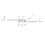
得られためっき鋼板から、幅:25mm、長さ:80mmの試験片を2枚切り出し、防錆油:550KH(パーカー興産製)に浸漬した後、24時間立て掛けて大気中で放置したものを供試材とした。図7に示すように、供試材5の接着される表面部分に接着剤6を塗布した後、重なり部の長さXが20mmとなるように重ね合わせる。接着剤6はE−56(サンライズMSI製)を使用し、スペーサー7(φ0.15mmのSUS304製ワイヤー)を使用して、接着剤厚さを試験片毎で一定に保つようにした。接着剤塗布後、乾燥炉で170℃の熱処理を20分間実施した後、オートグラフ(島津製作所製)で矢印8の方向に引っ張る引張り試験を実施し、引張剪断強度および剥離形態を測定し、下記の基準に従って評価した。なお、引張剪断強度は、同じ鋼成分とサイズを有する冷延鋼板(非めっき材)を用いて上記引張り試験を実施した際の強度に対する比率(%)で評価した。
(Evaluation of plating adhesion 1)
Two test pieces having a width of 25 mm and a length of 80 mm were cut out of the obtained plated steel sheet, immersed in rust-preventive oil: 550 KH (manufactured by Parker Kosan), and then left standing for 24 hours in the air. Samples were used. As shown in FIG. 7, an adhesive 6 is applied to a surface portion of the
<引張剪断強度の評価基準>
◎:特に良好(強度対比:90%超)
○:良好(強度対比:80%超、90%以下)
△:やや不良(強度対比:60%超、80%以下)
×:不良(強度対比:60%以下)
<Evaluation criteria for tensile shear strength>
◎: Particularly good (compared to strength: more than 90%)
:: good (compared to strength: more than 80%, 90% or less)
△: somewhat poor (compared to strength: more than 60%, 80% or less)
×: defective (compared to strength: 60% or less)
<剥離形態の評価基準>
◎:良好(接着剤内凝集剥離)
△:やや不良(一部めっき層/素材鋼板界面剥離)
×:不良(全面めっき層/素材鋼板界面剥離)
<Evaluation criteria for peeling form>
:: good (cohesive peeling in adhesive)
△: Slightly poor (partial plating layer / material steel sheet interface peeling)
×: defective (all-surface plating layer / material steel plate interface peeling)
尚、剥離形態の評価基準において、めっき層/素材鋼板界面剥離とは、めっき層と素材鋼板の界面で剥離することを意味するが、剥離形態によっては均一にめっき層と素材鋼板の界面で剥離しない場合もあるので、めっき層と素材鋼板の界面からめっき層側あるいは素材鋼板側に2μm以下の範囲内で剥離した場合もめっき層と素材鋼板の界面で剥離したものとする。 In the evaluation standard of the peeling form, the peeling at the interface between the plating layer and the material steel sheet means peeling at the interface between the plating layer and the material steel sheet. Since there is a case where it does not occur, even when peeling within a range of 2 μm or less from the interface between the plating layer and the material steel sheet to the plating layer side or the material steel sheet side, it is assumed that the film peels at the interface between the plating layer and the material steel sheet.
表2の評価結果から、本発明の合金化溶融亜鉛めっき鋼板(実施例)は、従来鋼板(比較例)に比べて著しくめっき層と鋼板の界面強度が上昇し、めっき密着性が改善していることがわかる。 From the evaluation results in Table 2, the alloyed hot-dip galvanized steel sheet of the present invention (Example) has significantly increased interfacial strength between the coating layer and the steel sheet as compared with the conventional steel sheet (Comparative Example), and has improved plating adhesion. You can see that there is.
表3に示す化学組成の鋼塊を1250℃に加熱して熱間圧延を行い、表面の黒皮を除去して厚さ:2.0mmの熱延鋼板とした。次いで圧下率:50%の冷間圧延を行って、厚さ:1.0mmの冷延鋼板とし、幅:70mm,長さ:180mmに切り出して素材鋼板とした。素材鋼板を5%塩酸に10秒間浸漬して酸洗した後、0.1vol%酸素を含有する窒素雰囲気(露点:+20℃)中で400℃、1秒間保持の一次加熱処理を行い、その後、5vol%水素を含有する窒素雰囲気(露点:+20℃)中で750℃、1秒間保持の二次加熱処理を施した。前記加熱処理した素材鋼板を用い、ラボめっきシミュレータで再結晶焼鈍とめっきを行った。再結晶焼鈍条件およびめっき条件は以下の通りである。 A steel ingot having a chemical composition shown in Table 3 was heated to 1250 ° C. and hot-rolled to remove black scale on the surface to obtain a hot-rolled steel sheet having a thickness of 2.0 mm. Next, cold rolling was performed at a draft of 50% to obtain a cold-rolled steel sheet having a thickness of 1.0 mm, and was cut into a width of 70 mm and a length of 180 mm to obtain a material steel sheet. After immersing the steel sheet in 5% hydrochloric acid for 10 seconds and pickling it, a primary heat treatment is performed at 400 ° C. for 1 second in a nitrogen atmosphere (dew point: + 20 ° C.) containing 0.1 vol% oxygen, and then 5 vol. A second heat treatment was performed at 750 ° C. for 1 second in a nitrogen atmosphere (dew point: + 20 ° C.) containing% hydrogen. Using the heat-treated steel sheet, recrystallization annealing and plating were performed by a laboratory plating simulator. Recrystallization annealing conditions and plating conditions are as follows.
<再結晶焼鈍>
雰囲気:5vol%水素+窒素(露点:−35℃)
温度:830℃
保持時間:20秒間
<Recrystallization annealing>
Atmosphere: 5vol% hydrogen + nitrogen (dew point: -35 ° C)
Temperature: 830 ° C
Holding time: 20 seconds
<めっき条件>
浴組成:Zn+0.13質量%Al(Fe飽和)
浴温:460℃
めっき時の板温:460℃
めっき時間:1秒間
めっき直前の雰囲気中の酸素濃度:表4に記載の条件(残部5vol%水素+窒素(露点:−35℃))
<Plating conditions>
Bath composition: Zn + 0.13 mass% Al (Fe saturated)
Bath temperature: 460 ° C
Plate temperature during plating: 460 ° C
Plating time: 1 second Oxygen concentration in the atmosphere immediately before plating: Conditions shown in Table 4 (remainder 5vol% hydrogen + nitrogen (dew point: -35 ° C))
得られためっき鋼板は、めっき層中にAl:0.2〜0.5質量%、Fe:0.5〜2質量%を含有するものであった。上記めっき処理の後に通電加熱炉内にて大気中で合金化処理を施した。合金化処理時の昇温速度、および合金化温度は表4に示す条件とした。 The obtained plated steel sheet contained 0.2 to 0.5% by mass of Al and 0.5 to 2% by mass of Fe in the plating layer. After the plating treatment, an alloying treatment was performed in the air in an electric heating furnace. The heating rate and the alloying temperature during the alloying treatment were set to the conditions shown in Table 4.
得られためっき鋼板について、再結晶焼鈍後めっきまでの冷却雰囲気、めっき層の厚さ、合金化処理における、昇温速度、温度および保持時間、めっき層中のFe含有率、めっき層と素材鋼板の界面に形成される微細凹凸の存在割合、ならびに展開面積比Sdrについては、上述の実施例1で説明した方法と同様に調査した。さらに、上述しためっき密着性1の評価を行なうとともに、以下に示すめっき密着性2の評価についても併せて行なった。それらの結果を表4に示す。また、得られためっき鋼板のめっき密着性の評価方法を以下に示すとともに評価結果を表4に併記する。
About the obtained plated steel sheet, cooling atmosphere until plating after recrystallization annealing, thickness of plated layer, heating rate, temperature and holding time in alloying treatment, Fe content in plated layer, plated layer and base steel sheet The existence ratio of the fine irregularities formed at the interface of and the development area ratio Sdr were investigated in the same manner as in the method described in the above-mentioned Example 1. Further, the plating adhesion 1 described above was evaluated, and the following
(めっき密着性2の評価)
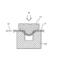
得られためっき鋼板から、幅:20mm、長さ:180mmの試験片を切り出し、エッジのバリを落として、防錆油:550KH(パーカー興産製)に浸漬した後、24時間立て掛けて大気中で放置したものを供試材とした。供試材9を、図8に示すような凹状金型10に設置し、供試材9の表面を凸状金型11を下降させ荷重Wで押し込む曲げ−曲げ戻し加工を加える試験を実施した。なお、金型の表面は試験毎に♯1200の研磨紙で研磨および付着異物の清掃を実施した。金型の押し込み荷重Pは8kNとし、供試材の引抜き速度は20mm/sとした。試験後、供試材を弱脱脂した後、金型との摺動部にセロハンテープ(ニチバン製、幅:24mm)を貼付け、剥がした時にセロハンテープに付着したZn量を蛍光X線によりカウント数として測定し、下記の基準に応じて評価した。
(Evaluation of plating adhesion 2)
A test piece having a width of 20 mm and a length of 180 mm was cut out from the obtained plated steel sheet, a burr on the edge was dropped, and immersion was carried out in rust-preventive oil: 550 KH (manufactured by Parker Kosan). The sample left as a test material was used. The
<めっき密着性2の評価基準>
◎:特に良好(カウント数:25以下)
○:良好(カウント数:25超え、50以下)
△:やや不良(カウント数:50超え、150以下)
×:不良(カウント数:150超え)
<Evaluation criteria for plating
◎: Particularly good (count: 25 or less)
:: good (count: more than 25, less than 50)
△: Somewhat poor (count: more than 50, less than 150)
×: defective (count: more than 150)
表4の評価結果から、本発明の合金化溶融亜鉛めっき鋼板(実施例)は、従来鋼板(比較例)に比べて著しくめっき層と鋼板の界面強度が上昇し、めっき密着性が改善していることがわかる。 From the evaluation results in Table 4, the alloyed hot-dip galvanized steel sheet of the present invention (Example) has significantly increased interfacial strength between the plating layer and the steel sheet and improved plating adhesion as compared with the conventional steel sheet (Comparative Example). You can see that there is.
表5に示す化学組成の鋼塊を1250℃に加熱して熱間圧延を行い、表面の黒皮を除去して厚さ:2.0mmの熱延鋼板とした。次いで圧下率:65%の冷間圧延を行って、厚さ:0.7mmの冷延鋼板とし、露点:−30℃の3vol%水素を含有する窒素雰囲気中の加熱炉内で830℃の一次加熱処理を行い、幅:70mm,長さ:180mmに切り出して素材鋼板とした。素材鋼板を5%塩酸に10秒間浸漬して酸洗した後、ラボめっきシミュレータで再結晶焼鈍とめっきを行った。再結晶焼鈍条件およびめっき条件は以下の通りである。 A steel ingot having the chemical composition shown in Table 5 was heated to 1250 ° C. and hot-rolled to remove black scale on the surface to obtain a hot-rolled steel sheet having a thickness of 2.0 mm. Next, cold rolling is performed at a rolling reduction of 65% to form a cold-rolled steel sheet having a thickness of 0.7 mm, and a primary heating of 830 ° C is performed in a heating furnace in a nitrogen atmosphere containing 3 vol% hydrogen at a dew point of -30 ° C. After the treatment, it was cut into a width: 70 mm and a length: 180 mm to obtain a material steel plate. The base steel sheet was immersed in 5% hydrochloric acid for 10 seconds and pickled, then recrystallized and plated by a lab plating simulator. Recrystallization annealing conditions and plating conditions are as follows.
<再結晶焼鈍>
雰囲気:5vol%水素+窒素(露点:−35℃)
温度:750℃
保持時間:20秒間
<Recrystallization annealing>
Atmosphere: 5vol% hydrogen + nitrogen (dew point: -35 ° C)
Temperature: 750 ° C
Holding time: 20 seconds
<めっき条件>
浴組成:Zn+0.14質量%Al(Fe飽和)
浴温:460℃
めっき時の板温:460℃
めっき時間:1秒間
めっき直前の雰囲気中の酸素濃度:表6に記載の条件(残部5vol%水素+窒素(露点:−35℃))
<Plating conditions>
Bath composition: Zn + 0.14 mass% Al (Fe saturated)
Bath temperature: 460 ° C
Plate temperature during plating: 460 ° C
Plating time: 1 second Oxygen concentration in the atmosphere immediately before plating: Conditions shown in Table 6 (
得られためっき鋼板は、めっき層中にAl:0.2〜0.5質量%、Fe:0.5〜2質量%を含有するものであった。上記めっき処理の後に通電加熱炉内にて大気中で合金化処理を施した。合金化処理時の昇温速度、および合金化温度は表6に示す条件とした。 The obtained plated steel sheet contained 0.2 to 0.5% by mass of Al and 0.5 to 2% by mass of Fe in the plating layer. After the plating treatment, an alloying treatment was performed in the air in an electric heating furnace. The heating rate and the alloying temperature during the alloying treatment were set to the conditions shown in Table 6.
得られためっき鋼板について、再結晶焼鈍後めっきまでの冷却雰囲気、めっき層の厚さ、合金化処理における、昇温速度、温度および保持時間、めっき層中のFe含有率、めっき層と素材鋼板の界面に形成される微細凹凸の存在割合、ならびに展開面積比Sdrについては、上述の実施例1で説明した方法と同様に調査した。さらに、上述しためっき密着性1の評価を行なうとともに、以下に示すめっき密着性3および4の評価についても併せて行なった。それらの結果を表6に示す。
About the obtained plated steel sheet, cooling atmosphere until plating after recrystallization annealing, thickness of plated layer, heating rate, temperature and holding time in alloying treatment, Fe content in plated layer, plated layer and base steel sheet The existence ratio of the fine irregularities formed at the interface of and the development area ratio Sdr were investigated in the same manner as in the method described in the above-mentioned Example 1. Further, the plating adhesion 1 described above was evaluated, and the following
(めっき密着性3の評価)
得られためっき鋼板から、幅:40mm、長さ:100mmの試験片を切り出し、セロハンテープ(ニチバン製、幅:24mm)を長さ:50mmの位置に貼り、テープ面を90°内側に曲げた後、曲げ戻しを行なってセロハンテープを剥がした時に付着したZn量を蛍光X線によりカウント数として測定した。測定したZnカウント数を試験片幅:単位長さ(1m)当たりのカウント数に補正して、下記の基準に応じて評価した。
(Evaluation of plating adhesion 3)
From the obtained plated steel sheet, a test piece having a width of 40 mm and a length of 100 mm was cut out, a cellophane tape (made by Nichiban, width: 24 mm) was attached at a position of a length of 50 mm, and the tape face was bent inward by 90 °. Thereafter, the amount of Zn adhering when the cellophane tape was peeled off after bending was measured as a count number by fluorescent X-ray. The measured Zn count was corrected to the test strip width: the count per unit length (1 m), and evaluated according to the following criteria.
<めっき密着性3の評価基準>
◎:特に良好(カウント数:500以下)
○:良好(カウント数:500超え、1000以下)
△:やや不良(カウント数:1000超え、3000以下)
×:不良(カウント数:3000超え)
<Evaluation criteria for plating
◎: Particularly good (count: 500 or less)
:: good (count: more than 500, less than 1000)
△: Somewhat poor (count: more than 1000, less than 3000)
×: defective (count: over 3000)
(めっき密着性4の評価)
得られためっき鋼板から、幅:70mm、長さ:150mmの試験片を切り出し、防錆油:550KH(パーカー興産製)に浸漬した後、24時間立て掛けて大気中で放置したものを供試材とした。供試材13の両端部を、図9に示すようなビード付き金型16を構成するダイ14およびしわ押え15の間で挟持した状態で、供試材13の裏面からポンチ17で押し込んでコの字型に成形する試験を実施した。なお、金型の表面は試験毎に♯1000の研磨紙で研磨および付着異物の清掃を実施した。しわ押え力Pは12kNとし、ポンチ速度は100mm/minとした。試験後、供試材を弱脱脂した後、凸側にセロハンテープ(ニチバン製、幅:24mm)を貼り付け、剥がした時にセロハンテープに付着したZn量を蛍光X線によりカウント数として測定し、下記の基準に応じて評価した。
(Evaluation of plating adhesion 4)
A test piece having a width: 70 mm and a length: 150 mm was cut out from the obtained plated steel sheet, immersed in rust-preventive oil: 550 KH (manufactured by Parker Kosan), left standing for 24 hours in the air, and used as a test material. And In a state where both ends of the
<めっき密着性4の評価基準>
◎:特に良好(カウント数:50以下)
○:良好(カウント数:50超え、100以下)
△:やや不良(カウント数:100超え、300以下)
×:不良(カウント数:300超え)
<Evaluation criteria for plating adhesion 4>
◎: Particularly good (count: 50 or less)
:: good (count: more than 50, less than 100)
△: Somewhat poor (count: more than 100, less than 300)
×: defective (count: more than 300)
表6の評価結果から、本発明の合金化溶融亜鉛めっき鋼板(実施例)は、従来鋼板(比較例)に比べて著しくめっき層と鋼板の界面強度が上昇し、めっき密着性が改善していることがわかる。 From the evaluation results in Table 6, the alloyed hot-dip galvanized steel sheet of the present invention (Example) has significantly increased interfacial strength between the coating layer and the steel sheet as compared with the conventional steel sheet (Comparative Example), and has improved plating adhesion. You can see that there is.
本発明の合金化溶融亜鉛めっき鋼板は、めっき層と素材鋼板との界面でのめっき密着性が従来にはない著しく優れた合金化溶融亜鉛めっき鋼板であり、自動車、家電、建材等の分野において、加工時のめっき層の剥離という問題が無く、加工後の外観が良好で、かつ充分な防錆性を維持することができる。従って、あらゆる形状の部品に対して高強度化や軽量化を達成することができるという産業上極めて有用な効果をもたらすことができる。 The alloyed hot-dip galvanized steel sheet of the present invention is an alloyed hot-dip galvanized steel sheet having extremely excellent plating adhesion at the interface between the coating layer and the material steel sheet, which has never been seen before, and is used in the fields of automobiles, home appliances, building materials, and the like. There is no problem of peeling of the plating layer during processing, the appearance after processing is good, and sufficient rust prevention can be maintained. Therefore, it is possible to bring about an industrially useful effect that high strength and light weight can be achieved for components of all shapes.
1 凹凸曲線
2 谷
3、4 山
5 供試材
6 接着剤
7 スペーサー
8 矢印
9 供試材
10 凹状金型
11 凸状金型
12 矢印
13 供試材
14 ダイ
15 しわ押さえ
16 ビード付金型
17 ポンチ
DESCRIPTION OF SYMBOLS 1 Concavo-
10 Concave mold
11 Convex mold
12 arrows
13 Test material
14 dies
15 Wrinkle holder
16 Die with bead
17 punch
Claims (10)
記
[C]+[P]≦[Si]・・・・・・・・・・・・(1)
但し、[C]、[P]および[Si]は、それぞれ素材鋼板中のC、PおよびSiの含有量(質量%)を意味する。 The composition according to claim 1 or 2, wherein the material steel sheet contains, by mass%, C: 0.25% or less, Si: 0.03 to 2.0%, and P: 0.005 to 0.07%, and the following formula (1) is satisfied. An alloyed hot-dip galvanized steel sheet with excellent plating adhesion.
Record
[C] + [P] ≦ [Si] (1)
However, [C], [P] and [Si] mean the contents (% by mass) of C, P and Si in the raw steel sheet, respectively.
記
[C]+[P]≦[Si]・・・・・・・・・・・・(1)
但し、[C]、[P]および[Si]は、それぞれ素材鋼板中のC、PおよびSiの含有量(質量%)を意味する。 Si in steel selects the material steel sheet which contains C: 0.25% or less, Si: 0.03-2.0% and P: 0.005-0.07% by mass%, and has a composition satisfying the following formula (1). After heat treatment so that the surface is not oxidized, it is cooled to a plating temperature in an atmosphere having an oxygen concentration of 0.005 vol% or less, and the material steel sheet is immersed in a hot-dip galvanizing bath to form a plating layer. An alloyed hot-dip galvanized steel sheet with excellent plating adhesion, characterized in that it is heated to a temperature range of 460 to 600 ° C at the above-mentioned heating rate, and is subjected to alloying treatment of a plating layer while maintaining the heating temperature range. Manufacturing method.
Record
[C] + [P] ≦ [Si] (1)
However, [C], [P] and [Si] mean the contents (% by mass) of C, P and Si in the raw steel sheet, respectively.
記
ST≧3.25/[Si] ・・・・・(2)
但し、式中のSTは昇温速度(℃/s)であり、[Si]は鋼板中のSi含有量(質量%)である。 The composition according to claim 8 or 9, wherein the material steel sheet further comprises one or more selected from among Ti: 0.2% or less, Nb: 0.2% or less, and V: 0.2% or less by mass%. And a method for producing an alloyed hot-dip galvanized steel sheet having excellent plating adhesion, wherein the heating rate and the Si content in the base steel sheet satisfy the following expression (2).
Record
ST ≧ 3.25 / [Si] ・ ・ ・ ・ ・ (2)
Here, ST in the formula is a heating rate (° C./s), and [Si] is the Si content (% by mass) in the steel sheet.
Priority Applications (8)
| Application Number | Priority Date | Filing Date | Title |
|---|---|---|---|
| JP2004013269A JP4729850B2 (en) | 2003-02-10 | 2004-01-21 | Alloyed hot-dip galvanized steel sheet with excellent plating adhesion and method for producing the same |
| CA2498223A CA2498223C (en) | 2003-02-10 | 2004-02-05 | Galvannealed steel sheet excellent in coating adhesion and manufacturing method thereof |
| EP04708495.9A EP1595969B1 (en) | 2003-02-10 | 2004-02-05 | Galvannealed steel sheet excellent in coating adhesion and manufacturing method thereof |
| US10/527,182 US20060057417A1 (en) | 2003-02-10 | 2004-02-05 | Steel sheet plated by hot dipping with alloyed zinc with excellent adhesion and process for producing the same |
| KR1020057006326A KR100675565B1 (en) | 2003-02-10 | 2004-02-05 | Alloyed hot dip galvanized steel sheet with excellent plating adhesion and its manufacturing method |
| AU2004209947A AU2004209947B2 (en) | 2003-02-10 | 2004-02-05 | Steel sheet plated by hot dipping with alloyed zinc with excellent adhesion and process for producing the same |
| PCT/JP2004/001209 WO2004070075A1 (en) | 2003-02-10 | 2004-02-05 | Steel sheet plated by hot dipping with alloyed zinc with excellent adhesion and process for producing the same |
| TW093103023A TW200424353A (en) | 2003-02-10 | 2004-02-10 | Steel sheet plated by hot dipping with alloyed zinc with excellent adhesion and process for producing the same |
Applications Claiming Priority (7)
| Application Number | Priority Date | Filing Date | Title |
|---|---|---|---|
| JP2003032311 | 2003-02-10 | ||
| JP2003032500 | 2003-02-10 | ||
| JP2003032321 | 2003-02-10 | ||
| JP2003032500 | 2003-02-10 | ||
| JP2003032311 | 2003-02-10 | ||
| JP2003032321 | 2003-02-10 | ||
| JP2004013269A JP4729850B2 (en) | 2003-02-10 | 2004-01-21 | Alloyed hot-dip galvanized steel sheet with excellent plating adhesion and method for producing the same |
Publications (2)
| Publication Number | Publication Date |
|---|---|
| JP2004263295A true JP2004263295A (en) | 2004-09-24 |
| JP4729850B2 JP4729850B2 (en) | 2011-07-20 |
Family
ID=32854419
Family Applications (1)
| Application Number | Title | Priority Date | Filing Date |
|---|---|---|---|
| JP2004013269A Expired - Fee Related JP4729850B2 (en) | 2003-02-10 | 2004-01-21 | Alloyed hot-dip galvanized steel sheet with excellent plating adhesion and method for producing the same |
Country Status (8)
| Country | Link |
|---|---|
| US (1) | US20060057417A1 (en) |
| EP (1) | EP1595969B1 (en) |
| JP (1) | JP4729850B2 (en) |
| KR (1) | KR100675565B1 (en) |
| AU (1) | AU2004209947B2 (en) |
| CA (1) | CA2498223C (en) |
| TW (1) | TW200424353A (en) |
| WO (1) | WO2004070075A1 (en) |
Cited By (17)
| Publication number | Priority date | Publication date | Assignee | Title |
|---|---|---|---|---|
| JP2006274288A (en) * | 2005-03-28 | 2006-10-12 | Jfe Steel Kk | High-strength hot-dip galvanized steel sheet with excellent surface appearance |
| JP2008274360A (en) * | 2007-04-27 | 2008-11-13 | Nippon Steel Corp | High strength steel plate with controlled yield point elongation and its manufacturing method |
| JP2010150660A (en) * | 2008-12-23 | 2010-07-08 | Posco | Method for producing hot dip galvanized steel sheet of high manganese steel having excellent plating surface quality |
| JP2010532820A (en) * | 2007-06-29 | 2010-10-14 | アルセロールミタル・フランス | Method for producing alloyed galvanized steel sheet by DFF adjustment |
| WO2011025042A1 (en) * | 2009-08-31 | 2011-03-03 | 新日本製鐵株式会社 | High-strength hot-dip galvanized steel sheet and process for producing same |
| JP2011094215A (en) * | 2009-10-30 | 2011-05-12 | Kobe Steel Ltd | High-tensile hot-dip galvannealed steel sheet superior in adhesiveness of plated film, and method for manufacturing the same |
| JP2012149307A (en) * | 2011-01-20 | 2012-08-09 | Jfe Steel Corp | Method for producing hot dip galvannealed steel sheet having excellent plating adhesion and sliding property |
| US9181613B2 (en) | 2011-04-20 | 2015-11-10 | Kobe Steel, Ltd. | High tensile strength hot-dip galvannealed steel sheet having excellent coated-layer adhesiveness and method for producing same |
| WO2015186827A1 (en) * | 2014-06-05 | 2015-12-10 | Jfeスチール株式会社 | Steel sheet for containers |
| WO2016002141A1 (en) * | 2014-07-02 | 2016-01-07 | Jfeスチール株式会社 | Method for manufacturing high-strength hot-dip galvanized steel sheet |
| WO2016031556A1 (en) * | 2014-08-29 | 2016-03-03 | 株式会社神戸製鋼所 | Original sheet for hot-dip galvanization or alloyed hot-dip galvanization, production method therefor, and hot-dip galvanized steel sheet or alloyed hot-dip galvanized steel sheet |
| JP2016084527A (en) * | 2014-10-24 | 2016-05-19 | Jfeスチール株式会社 | Steel sheet for vessel and manufacturing method thereof |
| JP2016163906A (en) * | 2015-02-27 | 2016-09-08 | Jfeスチール株式会社 | Silicon-containing hot-rolled pickled steel sheet and method for production thereof |
| KR20190006554A (en) * | 2016-06-27 | 2019-01-18 | 제이에프이 스틸 가부시키가이샤 | High Strength Alloying Hot-Dip Galvanized Steel Sheet and Manufacturing Method Thereof |
| JP2019119912A (en) * | 2018-01-09 | 2019-07-22 | 三菱マテリアル株式会社 | Dlc film coated member |
| WO2022209305A1 (en) * | 2021-04-02 | 2022-10-06 | 日本製鉄株式会社 | Steel sheet and method for producing same |
| JPWO2022209306A1 (en) * | 2021-04-02 | 2022-10-06 |
Families Citing this family (10)
| Publication number | Priority date | Publication date | Assignee | Title |
|---|---|---|---|---|
| KR20070043891A (en) * | 2004-09-15 | 2007-04-25 | 신닛뽄세이테쯔 카부시키카이샤 | High strength parts and its manufacturing method |
| KR100711445B1 (en) * | 2005-12-19 | 2007-04-24 | 주식회사 포스코 | Manufacturing method of hot-dip galvanized hot dip galvanized steel sheet with excellent plating adhesion and impact characteristics, manufacturing method of hot formed parts using this steel sheet |
| KR102099636B1 (en) | 2008-03-13 | 2020-04-13 | 블루스코프 스틸 리미티드 | Metal-coated steel strip |
| EP3757245A1 (en) | 2009-03-13 | 2020-12-30 | Bluescope Steel Limited | Corrosion protection with al / zn-based coatings |
| KR20120075260A (en) * | 2010-12-28 | 2012-07-06 | 주식회사 포스코 | Hot dip plated steel sheet excellent in plating adhesiveness and method for manufacturing the hot dip plated steel sheet |
| JP6290042B2 (en) * | 2014-08-27 | 2018-03-07 | 株式会社神戸製鋼所 | Aluminum alloy material and bonded body with excellent adhesion durability, or automobile parts |
| KR101858852B1 (en) * | 2016-12-16 | 2018-06-28 | 주식회사 포스코 | Cold-rolled steel sheet and galvanized steel sheet having excelent elonggation, hole expansion ration and yield strength and method for manufacturing thereof |
| CN108611601B (en) * | 2018-04-23 | 2021-03-09 | 南方科技大学 | An interface-enhanced composite material and use thereof |
| DE102020124488A1 (en) | 2020-09-21 | 2022-03-24 | Thyssenkrupp Steel Europe Ag | Sheet metal component and method for its manufacture |
| DE102022102111A1 (en) | 2022-01-31 | 2023-08-03 | Thyssenkrupp Steel Europe Ag | Uncoated cold-rolled steel sheet for hot forming, method of manufacturing a hot-formed sheet steel component and hot-formed sheet steel component |
Citations (6)
| Publication number | Priority date | Publication date | Assignee | Title |
|---|---|---|---|---|
| JPH05263207A (en) * | 1992-03-18 | 1993-10-12 | Nippon Steel Corp | High Si content high strength galvanized steel sheet |
| JPH0734213A (en) * | 1993-07-19 | 1995-02-03 | Sumitomo Metal Ind Ltd | Alloyed hot-dip galvanized steel sheet with excellent interfacial adhesion and method for producing the same |
| JPH1096064A (en) * | 1996-08-01 | 1998-04-14 | Sumitomo Metal Ind Ltd | Alloyed hot-dip galvanized steel sheet and method for producing the same |
| JP2000290730A (en) * | 1999-02-02 | 2000-10-17 | Kawasaki Steel Corp | Method for producing high-strength hot-dip galvanized steel sheet with excellent strength-ductility balance |
| JP2001303226A (en) * | 2000-04-25 | 2001-10-31 | Sumitomo Metal Ind Ltd | Alloyed hot-dip galvanized high-strength steel sheet with excellent workability and plating adhesion |
| JP2001335908A (en) * | 2000-05-23 | 2001-12-07 | Sumitomo Metal Ind Ltd | Alloyed hot-dip galvanized steel sheet and method for producing the same |
Family Cites Families (3)
| Publication number | Priority date | Publication date | Assignee | Title |
|---|---|---|---|---|
| US6368728B1 (en) * | 1998-11-18 | 2002-04-09 | Kawasaki Steel Corporation | Galvannealed steel sheet and manufacturing method |
| KR100679796B1 (en) * | 1999-02-25 | 2007-02-07 | 제이에프이 스틸 가부시키가이샤 | Steel sheet, hot-dip galvanized steel and alloyed hot-dip galvanized steel and their manufacturing method |
| DE60224557T4 (en) * | 2001-10-04 | 2015-06-25 | Nippon Steel & Sumitomo Metal Corporation | A tensile high strength thin steel sheet having excellent shape fixing property and manufacturing method therefor |
-
2004
- 2004-01-21 JP JP2004013269A patent/JP4729850B2/en not_active Expired - Fee Related
- 2004-02-05 AU AU2004209947A patent/AU2004209947B2/en not_active Ceased
- 2004-02-05 CA CA2498223A patent/CA2498223C/en not_active Expired - Fee Related
- 2004-02-05 US US10/527,182 patent/US20060057417A1/en not_active Abandoned
- 2004-02-05 WO PCT/JP2004/001209 patent/WO2004070075A1/en not_active Ceased
- 2004-02-05 KR KR1020057006326A patent/KR100675565B1/en not_active Expired - Lifetime
- 2004-02-05 EP EP04708495.9A patent/EP1595969B1/en not_active Expired - Lifetime
- 2004-02-10 TW TW093103023A patent/TW200424353A/en unknown
Patent Citations (6)
| Publication number | Priority date | Publication date | Assignee | Title |
|---|---|---|---|---|
| JPH05263207A (en) * | 1992-03-18 | 1993-10-12 | Nippon Steel Corp | High Si content high strength galvanized steel sheet |
| JPH0734213A (en) * | 1993-07-19 | 1995-02-03 | Sumitomo Metal Ind Ltd | Alloyed hot-dip galvanized steel sheet with excellent interfacial adhesion and method for producing the same |
| JPH1096064A (en) * | 1996-08-01 | 1998-04-14 | Sumitomo Metal Ind Ltd | Alloyed hot-dip galvanized steel sheet and method for producing the same |
| JP2000290730A (en) * | 1999-02-02 | 2000-10-17 | Kawasaki Steel Corp | Method for producing high-strength hot-dip galvanized steel sheet with excellent strength-ductility balance |
| JP2001303226A (en) * | 2000-04-25 | 2001-10-31 | Sumitomo Metal Ind Ltd | Alloyed hot-dip galvanized high-strength steel sheet with excellent workability and plating adhesion |
| JP2001335908A (en) * | 2000-05-23 | 2001-12-07 | Sumitomo Metal Ind Ltd | Alloyed hot-dip galvanized steel sheet and method for producing the same |
Cited By (31)
| Publication number | Priority date | Publication date | Assignee | Title |
|---|---|---|---|---|
| JP2006274288A (en) * | 2005-03-28 | 2006-10-12 | Jfe Steel Kk | High-strength hot-dip galvanized steel sheet with excellent surface appearance |
| JP2008274360A (en) * | 2007-04-27 | 2008-11-13 | Nippon Steel Corp | High strength steel plate with controlled yield point elongation and its manufacturing method |
| JP2010532820A (en) * | 2007-06-29 | 2010-10-14 | アルセロールミタル・フランス | Method for producing alloyed galvanized steel sheet by DFF adjustment |
| JP2010150660A (en) * | 2008-12-23 | 2010-07-08 | Posco | Method for producing hot dip galvanized steel sheet of high manganese steel having excellent plating surface quality |
| US9109275B2 (en) | 2009-08-31 | 2015-08-18 | Nippon Steel & Sumitomo Metal Corporation | High-strength galvanized steel sheet and method of manufacturing the same |
| WO2011025042A1 (en) * | 2009-08-31 | 2011-03-03 | 新日本製鐵株式会社 | High-strength hot-dip galvanized steel sheet and process for producing same |
| JP2011094215A (en) * | 2009-10-30 | 2011-05-12 | Kobe Steel Ltd | High-tensile hot-dip galvannealed steel sheet superior in adhesiveness of plated film, and method for manufacturing the same |
| JP2012149307A (en) * | 2011-01-20 | 2012-08-09 | Jfe Steel Corp | Method for producing hot dip galvannealed steel sheet having excellent plating adhesion and sliding property |
| US9181613B2 (en) | 2011-04-20 | 2015-11-10 | Kobe Steel, Ltd. | High tensile strength hot-dip galvannealed steel sheet having excellent coated-layer adhesiveness and method for producing same |
| WO2015186827A1 (en) * | 2014-06-05 | 2015-12-10 | Jfeスチール株式会社 | Steel sheet for containers |
| JP6079891B2 (en) * | 2014-06-05 | 2017-02-15 | Jfeスチール株式会社 | Steel plate for containers |
| WO2016002141A1 (en) * | 2014-07-02 | 2016-01-07 | Jfeスチール株式会社 | Method for manufacturing high-strength hot-dip galvanized steel sheet |
| US10570474B2 (en) | 2014-07-02 | 2020-02-25 | Jfe Steel Corporation | Method for manufacturing high-strength galvanized steel sheet |
| CN106661657A (en) * | 2014-07-02 | 2017-05-10 | 杰富意钢铁株式会社 | Method for manufacturing high-strength hot-dip galvanized steel sheet |
| JP6086162B2 (en) * | 2014-07-02 | 2017-03-01 | Jfeスチール株式会社 | Method for producing high-strength hot-dip galvanized steel sheet |
| US10597764B2 (en) | 2014-08-29 | 2020-03-24 | Kobe Steel, Ltd. | Substrate for hot-dip galvanizing or hot-dip galvannealing, production method therefor, and hot-dip galvanized steel sheet or hot-dip galvannealed steel sheet |
| JP2016050356A (en) * | 2014-08-29 | 2016-04-11 | 株式会社神戸製鋼所 | Original sheet for hot-dip galvanization or alloyed hot-dip galvanization, production method thereof, and hot-dip galvanized steel sheet or alloyed hot-dip galvanized steel sheet |
| WO2016031556A1 (en) * | 2014-08-29 | 2016-03-03 | 株式会社神戸製鋼所 | Original sheet for hot-dip galvanization or alloyed hot-dip galvanization, production method therefor, and hot-dip galvanized steel sheet or alloyed hot-dip galvanized steel sheet |
| JP2016084527A (en) * | 2014-10-24 | 2016-05-19 | Jfeスチール株式会社 | Steel sheet for vessel and manufacturing method thereof |
| JP2016163906A (en) * | 2015-02-27 | 2016-09-08 | Jfeスチール株式会社 | Silicon-containing hot-rolled pickled steel sheet and method for production thereof |
| US11384407B2 (en) | 2016-06-27 | 2022-07-12 | Jfe Steel Corporation | High-strength galvannealed steel sheet |
| KR20190006554A (en) * | 2016-06-27 | 2019-01-18 | 제이에프이 스틸 가부시키가이샤 | High Strength Alloying Hot-Dip Galvanized Steel Sheet and Manufacturing Method Thereof |
| KR102249246B1 (en) * | 2016-06-27 | 2021-05-06 | 제이에프이 스틸 가부시키가이샤 | High-strength alloyed hot-dip galvanized steel sheet and its manufacturing method |
| JP2019119912A (en) * | 2018-01-09 | 2019-07-22 | 三菱マテリアル株式会社 | Dlc film coated member |
| JP7127992B2 (en) | 2018-01-09 | 2022-08-30 | 三菱マテリアル株式会社 | DLC coating material |
| WO2022209305A1 (en) * | 2021-04-02 | 2022-10-06 | 日本製鉄株式会社 | Steel sheet and method for producing same |
| JPWO2022209306A1 (en) * | 2021-04-02 | 2022-10-06 | ||
| WO2022209306A1 (en) * | 2021-04-02 | 2022-10-06 | 日本製鉄株式会社 | Steel sheet and method for producing same |
| JPWO2022209305A1 (en) * | 2021-04-02 | 2022-10-06 | ||
| JP7662963B2 (en) | 2021-04-02 | 2025-04-16 | 日本製鉄株式会社 | Steel plate and its manufacturing method |
| JP7662962B2 (en) | 2021-04-02 | 2025-04-16 | 日本製鉄株式会社 | Steel plate and its manufacturing method |
Also Published As
| Publication number | Publication date |
|---|---|
| CA2498223A1 (en) | 2004-08-19 |
| KR20050061533A (en) | 2005-06-22 |
| EP1595969B1 (en) | 2017-06-28 |
| EP1595969A4 (en) | 2010-02-03 |
| KR100675565B1 (en) | 2007-01-30 |
| AU2004209947A1 (en) | 2004-08-19 |
| CA2498223C (en) | 2010-05-18 |
| EP1595969A1 (en) | 2005-11-16 |
| JP4729850B2 (en) | 2011-07-20 |
| US20060057417A1 (en) | 2006-03-16 |
| TW200424353A (en) | 2004-11-16 |
| AU2004209947B2 (en) | 2006-12-14 |
| WO2004070075A1 (en) | 2004-08-19 |
Similar Documents
| Publication | Publication Date | Title |
|---|---|---|
| JP4729850B2 (en) | Alloyed hot-dip galvanized steel sheet with excellent plating adhesion and method for producing the same | |
| KR101707984B1 (en) | HOT-DIP Al-Zn COATED STEEL SHEET | |
| JP6566128B2 (en) | Hot stamping body | |
| JP7670954B2 (en) | Galvannealed steel sheet for hot stamping and method for producing same | |
| JP4464720B2 (en) | High-strength hot-dip galvanized steel sheet and manufacturing method thereof | |
| JP5708884B2 (en) | Alloyed hot-dip galvanized steel sheet and manufacturing method thereof | |
| TW201934779A (en) | Fe-Al plated hot-stamped member and method for producing Fe-Al plated hot-stamped member | |
| JP2017066508A (en) | Galvanized steel sheet for hot pressing and manufacturing method of hot press-formed product | |
| US10927441B2 (en) | High-strength galvanized hot-rolled steel sheet and method for manufacturing same | |
| KR102741404B1 (en) | Hot stamp parts | |
| JP7619483B2 (en) | Galvanized steel sheet, component, and manufacturing method thereof | |
| CN111936659B (en) | High-strength alloyed hot-dip galvanized steel sheet and method for producing same | |
| CN116034177B (en) | Zn-plated hot stamped products | |
| JP7773087B2 (en) | Hot stamping parts | |
| CN100552076C (en) | Alloyed hot-dip galvanized steel sheet excellent in coating adhesion and manufacturing method thereof | |
| WO2024204646A1 (en) | Hot-dipped steel sheet, frame, and method for producing hot-dipped steel sheet | |
| US12371771B2 (en) | Plated steel | |
| CN113924379B (en) | Hot-pressing galvanized steel sheet, method for producing hot-pressing galvanized steel sheet, and hot-pressed molded body | |
| US12440883B2 (en) | Hot stamped member | |
| JP4720618B2 (en) | Alloyed hot-dip galvanized steel sheet and method for producing the same | |
| WO2023135981A1 (en) | Hot stamp molded article | |
| JP2006077329A (en) | High strength galvannealed steel sheet | |
| WO2025169778A1 (en) | Plated steel sheet and component including same | |
| WO2025169775A1 (en) | Plated steel sheet and component including same | |
| WO2025169776A1 (en) | Plated steel sheet and component including same |
Legal Events
| Date | Code | Title | Description |
|---|---|---|---|
| A621 | Written request for application examination |
Free format text: JAPANESE INTERMEDIATE CODE: A621 Effective date: 20061026 |
|
| A131 | Notification of reasons for refusal |
Free format text: JAPANESE INTERMEDIATE CODE: A131 Effective date: 20090811 |
|
| A521 | Request for written amendment filed |
Free format text: JAPANESE INTERMEDIATE CODE: A523 Effective date: 20091013 |
|
| RD03 | Notification of appointment of power of attorney |
Free format text: JAPANESE INTERMEDIATE CODE: A7423 Effective date: 20091013 |
|
| A131 | Notification of reasons for refusal |
Free format text: JAPANESE INTERMEDIATE CODE: A131 Effective date: 20100427 |
|
| A521 | Request for written amendment filed |
Free format text: JAPANESE INTERMEDIATE CODE: A523 Effective date: 20100617 |
|
| TRDD | Decision of grant or rejection written | ||
| A01 | Written decision to grant a patent or to grant a registration (utility model) |
Free format text: JAPANESE INTERMEDIATE CODE: A01 Effective date: 20110322 |
|
| A61 | First payment of annual fees (during grant procedure) |
Free format text: JAPANESE INTERMEDIATE CODE: A61 Effective date: 20110404 |
|
| FPAY | Renewal fee payment (event date is renewal date of database) |
Free format text: PAYMENT UNTIL: 20140428 Year of fee payment: 3 |
|
| R150 | Certificate of patent or registration of utility model |
Ref document number: 4729850 Country of ref document: JP Free format text: JAPANESE INTERMEDIATE CODE: R150 Free format text: JAPANESE INTERMEDIATE CODE: R150 |
|
| LAPS | Cancellation because of no payment of annual fees |