JP2004304841A - Radio communication system and mobile terminal used in radio communication system - Google Patents
Radio communication system and mobile terminal used in radio communication system Download PDFInfo
- Publication number
- JP2004304841A JP2004304841A JP2004166876A JP2004166876A JP2004304841A JP 2004304841 A JP2004304841 A JP 2004304841A JP 2004166876 A JP2004166876 A JP 2004166876A JP 2004166876 A JP2004166876 A JP 2004166876A JP 2004304841 A JP2004304841 A JP 2004304841A
- Authority
- JP
- Japan
- Prior art keywords
- communication system
- communication
- mobile terminal
- address
- application software
- Prior art date
- Legal status (The legal status is an assumption and is not a legal conclusion. Google has not performed a legal analysis and makes no representation as to the accuracy of the status listed.)
- Pending
Links
Images







Landscapes
- Data Exchanges In Wide-Area Networks (AREA)
- Mobile Radio Communication Systems (AREA)
Abstract
【課題】 複数の通信システムを用い、移動端末がどこに移動しても、その場所で利用可能な通信システムを選択して通信できるようにする。
【解決手段】 通信システム1の基地局BS1−1、BS1−2、…は、ゲートウェイGW1を介してインターネットに接続され、通信システム2における基地局BS2−1、BS2−2、…は、ゲートウェイGW2を介してインターネットに接続されており、各々のゲートウェイは、ルータ機能を有してインターネットとサブネットワーク間のルーティングを行うようになっており、移動端末20は、それぞれの通信システムにアクセス可能な複数の移動局ネットワークインターフェースとアプリケーションソフトが動作する部分との間にルータ機能を持つ切り替え手段を有し、アプリケーションソフトが動作する部分を複数の移動局ネットワークインターフェースのいずれか1つに接続して通信システムを切り替える。
【選択図】 図15
PROBLEM TO BE SOLVED: To use a plurality of communication systems and select a communication system that can be used in a place where the mobile terminal moves, so that communication can be performed.
.. In a communication system 1 are connected to the Internet via a gateway GW1, and base stations BS2-1, BS2-2,. Each gateway has a router function to perform routing between the Internet and a sub-network, and the mobile terminal 20 is connected to a plurality of communication systems capable of accessing the respective communication systems. Switching means having a router function between a mobile station network interface and a part on which application software operates, and connecting the part on which the application software operates to any one of a plurality of mobile station network interfaces Switch.
[Selection diagram] FIG.
Description
本発明は、無線通信システム、ネットワークおよび無線通信システムに用いられる移動端末に関する。 The present invention relates to a wireless communication system, a network, and a mobile terminal used in the wireless communication system.
従来、この種の無線通信システムにおいて、使用者が移動した場合、データの配信経路、すなわちルーティングを制御する技術として、いくつかの基地局をまとめて1つのドメインを形成し、ドメイン間をまたがる場合に、モバイルIPの技術を用いてルーティング制御するものがある(例えば、特許文献1、2参照)。
上記した従来技術では、ドメイン内ならびにドメイン間のルーティングを効率良く行うことは可能であるが、あくまでも基地局は同一の通信システムを前提においているため、そのまま複数の通信システムに適用することができない。 In the above-described conventional technology, it is possible to efficiently perform routing within a domain and between domains, but since the base station is based on the same communication system, it cannot be directly applied to a plurality of communication systems.
ところで、現在のディジタルセルラーシステムでは、音声通話だけではなく、データ通信のニーズも多い。こうしたデータ通信のニーズに対し、伝送レートの高速化が検討されている。 By the way, in the current digital cellular system, there are many needs for not only voice communication but also data communication. To meet such data communication needs, studies have been made to increase the transmission rate.
このような高速データ通信のトレンドに従い、データレートが高くなればなるほど、1つあたりの通信セルで処理すべき負荷も高くなり、かつ伝送のための周波数帯域を多く消費するため、必然的に使用周波数も高くせざるを得ず、電波の届く距離も短くなる。従って、セルのサイズが小さくなる。このような高速データ通信システムにおいては、既存の通信システムとの併用が考えられる。具体的には、後述する実施形態で詳述するように、高速ではあるがサービスエリアが狭くスポット的に配置された通信システム1と、低速では有るがサービスエリアが広く網羅的に配置された通信システム2とが並存することが考えられる。
In accordance with the trend of high-speed data communication, the higher the data rate, the higher the load that must be processed in one communication cell and the more the frequency band for transmission is consumed. The frequency must be increased, and the range of radio waves can be shortened. Therefore, the size of the cell is reduced. Such a high-speed data communication system may be used in combination with an existing communication system. More specifically, as will be described in detail in an embodiment to be described later, a
そこで、本発明は、複数の通信システムを用い、通信システムを切り替えながら通信を行えるようにする無線通信システムおよび無線通信システムに用いられる移動端末を提供することを目的とする。 Therefore, an object of the present invention is to provide a wireless communication system that enables communication while switching between communication systems using a plurality of communication systems, and a mobile terminal used in the wireless communication system.
上記目的を達成するため、請求項1〜3に記載の発明では、互いに異なる複数の通信システムで移動端末と通信を行うように構成された無線通信システムであって、各々の通信システムの基地局は、各通信システムごとにそれぞれ同一のサブネットワークに属し、各サブネットは各々に対して設けられたゲートウェイを介してインターネットに接続されており、各々のゲートウェイは、ルータ機能を有してインターネットとサブネットワーク間のルーティングを行うようになっており、移動端末は、それぞれの通信システムにアクセス可能な複数の移動局ネットワークインターフェースを備え、複数の移動局ネットワークインターフェースとアプリケーションソフトが動作する部分との間にルータ機能を持つ切り替え手段を有して、アプリケーションソフトが動作する部分を前記複数の移動局ネットワークインターフェースのいずれか1つに接続して通信システムを切り替えるように構成され、アプリケーションソフトが、前記複数の通信システムとは異なる固有のサブネットのアドレスを持って同一の発信者アドレスで通信することを特徴としている。
In order to achieve the above object, the invention according to
この発明によれば、ルータ機能を用いて通信システムの切り替えを適切に行うことができる。 ADVANTAGE OF THE INVENTION According to this invention, switching of a communication system can be performed appropriately using a router function.
請求項4に記載の発明では、請求項1〜3に記載の無線通信システムに用いられる移動端末を提供することができる。 According to the fourth aspect of the present invention, it is possible to provide a mobile terminal used in the wireless communication system according to the first to third aspects.
(第1実施形態)
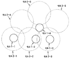
図1に、本発明の第1実施形態に係る無線通信システムの全体構成を示す。この無線通信システムは、通信システム1、2で構成されている。通信システム1は、例えばDSRC(Dedicated Short-Range Communication)や無線LANのように、高速で通信を行うことができるがサービスエリアが狭く離散的(スポット的)に通信を行うシステムであり、通信システム2は、携帯電話やPHSのように、比較的低速で通信を行うがサービスエリアが広く網羅的に通信を行う行うことができるシステムである。例えば、図2に示すように、通信システム1では、離散的に配置された狭域セル1−1、1−2、1−3、1−4、…において高速で通信が行われ、通信システム2では、網羅的に配置された広域セル2−1、2−2、2−3、2−4、2−5、2−6、…において比較的低速で通信が行われる。
(1st Embodiment)
FIG. 1 shows an overall configuration of a wireless communication system according to a first embodiment of the present invention. This wireless communication system includes
通信システム1における基地局BS1−1、BS1−2、BS1−3、…は、同一のサブネットワーク(サブネット1)に属し、サブネット1は、ゲートウェイGW1を介して、インターネットに接続されている。また、通信システム2における基地局BS2−1、BS2−2、BS2−3、…は、同一のサブネットワーク(サブネット2)に属し、サブネット2は、ゲートウェイGW2を介して、インターネットに接続されている。そして、移動端末20は、通信システム1、2のいずれかを用いて、インターネットを介しサーバにアクセスする。
The base stations BS1-1, BS1-2, BS1-3,... In the
また、移動端末20は、通信システム1にアクセス可能な移動局ネットワークインターフェースMS1と、通信システム2にアクセス可能な移動局ネットワークインターフェースMS2とを備え、通信システム1、2のうちのいずれか一方で通信を行うように構成されている。この場合、移動局ネットワークインターフェースMS1は、サブネット1のIP(インターネット)アドレスを用いてアクセスを行い、移動局ネットワークインターフェースMS2は、サブネット2のIPアドレスを用いてアクセスを行う。
Also, the mobile terminal 20 includes a mobile station network interface MS1 that can access the
ここで、移動端末20は、通信システム1では基地局BS1−1、BS1−2、BS1−3、…のいずれかと通信を行い、通信システム2では基地局BS2−1、BS2−2、BS2−3、…のいずれかと通信を行うが、それぞれの通信システムにおいて、移動端末20と通信を行う基地局は、いわゆるローミングによって決定される。ローミングとは、同一の通信システムにおいて、異なる基地局間でハンドオーバーしていく技術である。
Here, the mobile terminal 20 communicates with any of the base stations BS1-1, BS1-2, BS1-3,... In the
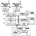
図3に、移動端末20の具体的な構成を示す。移動端末20は、上記した移動局ネットワークインターフェースMS1、MS2を構成する通信機21a、21bと、通信機21a、21bと移動端末20内の各部との信号の送受を行うインターフェース22a、22bと、通信システム切替部23と、ネットワークドライバ24と、アプリケーション部25と、受信電力モニタ26と、通信品質評価部27と、制御部28とから構成されている。なお、移動端末20において、図では各部がブロック的な構成として示されているが、ハードウェアとして必然的に構成される部分以外は、コンピュータを用いて実現することができる。
FIG. 3 shows a specific configuration of the mobile terminal 20. The mobile terminal 20 communicates with the
通信システム切替部23は、制御部28からの待機/送受切替信号に基づいて、インターフェース22a、22bを介し、通信機21a、21bをそれぞれ送受信可能状態(アクティブな状態)、待機状態(アクティブでない状態)のいずれかにする。ここで、待機状態とは、例えば、受信することはできるが送信することができないような状態をいう。なお、以下の説明では、通信機21a、21bの送受信可能状態を、通信システム1、2の送受信可能状態とし、通信機21a、21bの待機状態を、通信システム1、2の待機状態とする。
Based on the standby / transmission / reception switching signal from the
受信電力モニタ26は、通信機21a、21bの受信電力、すなわち通信システム1、2での受信電力をインターフェース22a、22bを介して検出する。通信品質評価部27は、ネットワークドライバ24から、通信機21a、21bのうち現在通信に使用されている通信機による通信品質の評価、すなわち通信システム1、2のうち現在通信に使用されている通信システムの通信品質の評価を行う。この通信品質の評価としては、例えばビットエラーレート(BER)を用いることができる。
The
アプリケーション部25は、Webブラウザ、電子メールなどのための種々のアプリケーションソフトからなり、これらのアプリケーションソフトによって通信が行われる。この場合、通信利用状況、すなわち送受信を実際に行っていることを示す情報が制御部28に通知される。
The
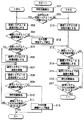
制御部28は、受信電力モニタ26の出力信号、通信品質評価部27の出力信号などによって、通信システム1、2のいずれか一方を送受信可能状態に、他方を待機状態にするように制御を行う。この制御処理を図4に示す。
The
まず、制御部28は、初期化処理として通信システム1、2を待機状態にする(ステップ101)。次に、受信電力モニタ26によって検出された通信システム1の受信電力に基づき、通信システム1で通信が可能か否かを判定する(ステップ102)。
First, the
移動端末20が狭域セル1−1、1−2、1−3、1−4、…のいずれかに位置し、通信システム1で通信が可能な場合には、通信システム1を送受信可能状態にする(ステップ103)。 When the mobile terminal 20 is located in one of the narrow-area cells 1-1, 1-2, 1-3, 1-4,... (Step 103).
次に、通信システム2が送受信可能状態になっているか否かを判定する(ステップ104)。最初にこのステップ104に到来したときには、初期化処理によって通信システム2が待機状態になっているため、その判定がNOになる。但し、その後の処理を経て、このステップ104に到来したとき、通信システム2が送受信可能状態になっていなければ、通信システム2を送受信可能状態にする(ステップ105)。
Next, it is determined whether the communication system 2 is in a transmission / reception enabled state (step 104). When the process first arrives at
そして、通信システム1で通信を実施するようにネットワークドライバ24を制御する(ステップ106)。また、通信システム1で通信を実施しているときの通信品質の評価を通信品質評価部27から得(ステップ107)、その通信品質の評価に基づいて通信システム1での通信が維持可能であるか否かを判定する(ステップ108)。通信システム1での通信が維持可能である場合は、ステップ106からステップ108の処理を繰り返す。
Then, the
また、移動端末20がそれまで位置していた狭域セルから移動し、通信システム1での通信が維持できなくなると、次に通信システム2を送受信可能状態にする(ステップ109)。
Further, when the mobile terminal 20 moves from the narrow area cell where it has been located and cannot maintain the communication in the
そして、通信システム1が送受信可能状態になっている場合(ステップ110の判定がYESの場合)には、通信システム1を待機状態にする(ステップ111)。続いて、通信システム2で通信を実施するようにネットワークドライバ24を制御する(ステップ112)。また、受信電力モニタ26から通信システム1での受信電力を得(ステップ113)、その受信電力に基づいて通信システム1で通信を開始することができるか否かを判定する(ステップ114)。通信システム1で通信を開始することができない場合は、ステップ112〜ステップ114の処理を繰り返す。
Then, when the
その後、移動端末20が狭域セルのいずれかに再度入り、通信システム1で通信を開始することができることを判定すると、上記したステップ103以降の処理に移行し、通信システム1で通信を実施するようにする。
Thereafter, when it is determined that the mobile terminal 20 re-enters one of the narrow-area cells and can start communication in the
このような制御とすることにより、高速な通信システムを優先的に使用して、トータルの伝送効率を高めるとともに、使用していない通信システムを待機状態にすることにより、消費電力を抑制できる。 With this control, the high-speed communication system is preferentially used to increase the total transmission efficiency, and the power consumption can be suppressed by putting the unused communication system in a standby state.
なお、上記した実施形態では、通信システム1、2の一方を送受信可能状態にし、他方を待機状態にするものを示したが、通信システム1、2の両方を送受信可能状態にしておき、通信システム1で通信を行えるときには通信システム1で通信を行い、通信システム1の通信が維持できなくなった場合に、通信システム2で通信を行うようにしてもよい。この場合の制御部28の制御処理を図5に示す。
In the embodiment described above, one of the
まず、制御部28は、初期化処理として通信システム2を送受信可能状態にする(ステップ201)。次に、受信電力モニタ26によって検出された通信システム1での受信電力に基づき、通信システム1で通信が可能か否かを判定する(ステップ202)。
First, the
通信システム1で通信が可能な場合には、通信システム1を送受信可能状態にする(ステップ203)。そして、通信システム1で通信を実施するようにネットワークドライバ24を制御する(ステップ204)。また、通信システム1で通信を実施しているときの通信品質の評価を通信品質評価部27から得(ステップ205)、その通信品質の評価に基づいて通信システム1での通信が維持可能であるか否かを判定する(ステップ206)。通信システム1での通信が維持可能である場合は、ステップ204〜ステップ206の処理を繰り返す。
If communication is possible in the
また、通信システム1での通信が維持できなくなると、次に通信システム2が送受信可能状態になっているか否かを判定する(ステップ207)。これは、通信システム2が一時的に広域セルの圏外に入り、切断されることも有り得るので、その接続をチェックするために行う。通信システム2が送受信可能状態になっていなければ、通信システム2を送受信可能な状態にする。(ステップ208)。
Further, when the communication in the
そして、通信システム2で通信を実施するようにネットワークドライバ24を制御する(ステップ209)。また、受信電力モニタ26から通信システム1での受信電力を得(ステップ210)、その受信電力に基づいて通信システム1で通信を開始することができるか否かを判定する(ステップ211)。通信システム1で通信を開始することができない場合は、ステップ209〜ステップ211の処理を繰り返す。
Then, the
その後、通信システム1で通信を開始することができることを判定すると、上記したステップ203以降の処理に移行し、通信システム1で通信を実施するようにする。
Thereafter, when it is determined that the communication can be started in the
このような制御とすることにより、サービスエリアの広い広域セルにおいて通信を行うことができる通信システム2を常にバックアップとして動かしておくことで、通信システムの切り替え時に通信が瞬断するのを防止することができる。 With such control, the communication system 2 capable of performing communication in a wide area cell having a wide service area is always operated as a backup, thereby preventing a momentary interruption of communication when the communication system is switched. Can be.
なお、上記した実施形態では、2つの通信システムとした場合について説明したが、3つ以上の通信システムとしてもよく、その場合には、より高速の通信システムが選択されていくように、通信システムが切り替えられる。 In the above-described embodiment, the case where two communication systems are used has been described. However, three or more communication systems may be used. In such a case, the communication system is selected so that a higher-speed communication system is selected. Is switched.
このように、この実施形態によれば、移動端末20がどこに移動しても、その場所で利用可能な、最も高速の通信システムを選択して通信することができる。また、通信システムごとにサブネットを分けているため、移動端末20と通信を行う場合のルーティングを容易に行うことができる。 Thus, according to this embodiment, no matter where the mobile terminal 20 moves, it is possible to select and communicate with the highest-speed communication system available at that location. In addition, since the subnet is divided for each communication system, routing when communicating with the mobile terminal 20 can be easily performed.
但し、上記したように2つの通信システム1、2を用いた場合、移動端末20からサーバへ通信する上り回線については、移動端末20でどちらの通信システムを使うかがわかっているため通常通り通信を行うことができるが、サーバから移動端末20に通信する下り回線については、通信システム1、2のいずれを使うかがわからず、そのためのルーティングが必要となる。
However, when the two
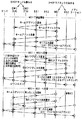
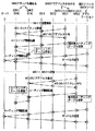
以下、この下り回線のルーティングについて説明する。このルーティングを行うため、この実施形態では、モバイルIPの技術を利用している。図6に示すように、通信システム1が属するサブネット1内のゲートウェイGW1にホームエージェントHAを設置し、通信システム2のサブネット2内のゲートウェイGW2にフォーリンエージェントFAを設置する。移動端末20が通信システム1のサービスエリア内にいる場合には、ホームアドレスを用いたアクセスを行い、移動端末20が通信システム2のサービスエリア内にいる場合には、フォーリンエージェントFAが決める気付アドレスを用いたアクセスを行う。この場合の信号のやり取りを図7、図8に示す。なお、この実施形態では、ゲートウェイGW1、GW2とも、それぞれDHCP(Dynamic Host Configuration Protocol)サーバを兼ねるものとしている。
Hereinafter, the downlink routing will be described. In order to perform this routing, this embodiment uses the technology of Mobile IP. As shown in FIG. 6, the home agent HA is installed in the gateway GW1 in the
図7は、移動端末20の起動時に通信システム1が利用可能な場合の信号のやり取りを示している。まず、移動端末20は、通信システム1を用いてホームエージェントHAにホームIPアドレスを要求する。ゲートウェイGW1はDHCPサーバを兼ねているので、その要求に対しホームIPアドレスを移動端末20に付与する。次に、移動端末20は、ホームエージェントHAにホームアドレスを登録する。この後、上り、下り回線とも、ホームアドレスを用いてサーバと通信することができる。この場合、アプリケーションソフトによってその通信が行われる。
FIG. 7 shows signal exchange when the
また、移動端末20が通信システム1から通信システム2に切り替えて通信を行うことになると、移動端末20は、通信システム2を用いてフォーリンエージェントFAに気付IPアドレスを要求する。ゲートウェイGW2はDHCPサーバを兼ねているので、その要求に対し気付IPアドレスを移動端末20に付与する。次に、移動端末20は、ホームエージェントHAに気付IPアドレスの登録を行う。この場合、気付IPアドレスは、フォーリンエージェントFAからインターネットを介してホームエージェントHAに登録される。この後、上り回線は、ホームアドレスを用いることにより、サーバと通信を行うことができる。また、下り回線は、サーバからホームアドレスを用いてインターネット経由でホームエージェントHAに送信が行われ、ホームエージェントHAから気付IPアドレスを用いてインターネット経由でフォーリンエージェントFAに送信が行われ、さらにフォーリンエージェントFAから基地局BS2を介して移動端末20に送信が行われる。すなわち、下り回線の場合、ホームエージェントHAとフォーリンエージェントFAによるIPトンネリングを用いて、サーバから移動端末20への送信が行われる。
When the mobile terminal 20 performs communication by switching from the
この後、移動端末20が通信システム1から通信システム2に切り替えて通信を行うことになると、移動端末20は、通信システム1を用いてホームエージェントHAに、ホームセグメント(通信システム1での通信)に戻ったことを通知する。この場合、不要になったIPアドレスを解放(返却)するようにしてもよい。このようにすれば、IPアドレス空間の有効利用を図ることができる。なお、IPアドレスを解放した場合は、通信システム2に切り替えるときに上記した気付IPアドレスを再度取得する必要があるが、IPアドレスを解放しなかった場合には、気付IPアドレスを再度取得する必要はない。
Thereafter, when the mobile terminal 20 performs communication by switching from the
この後は、上記したのと同様、上り、下り回線とも、ホームアドレスを用いてサーバと通信することができる。 Thereafter, in the same manner as described above, the uplink and downlink can communicate with the server using the home address.
図8に、移動端末20の起動時に通信システム1が利用できない場合の信号のやり取りを示す。まず、移動端末20は、通信システム2を用いてフォーリンエージェントFAに気付IPアドレスを要求する。フォーリンエージェントFAは、その要求に対し気付IPアドレスを移動端末20に付与する。次に、移動端末20は、ホームアドレスを確保するための要求を行う。この要求は、フォーリンエージェントFAからインターネットを介してホームエージェントHAに伝えられ、ホームアドレスが確保される。そして、ホームエージェントHAからフォーリンエージェントFAを介し、さらに基地局BS2を介して、移動端末20にホームアドレスが通知される。移動端末20は、確保されたホームアドレスを制御ソフトによって保存する。そして、通信を行う場合に、上り回線は、移動端末20からホームアドレスを用いてサーバに送信が行われ、下り回線は、サーバから、ホームエージェントHA、フォーリンエージェントFAによるIPトンネリングを用いて移動端末20に送信が行われる。
FIG. 8 shows the exchange of signals when the
また、移動端末20が通信システム1から通信システム2に切り替えて通信を行うことになると、移動端末20は、制御ソフトにより保存されていたホームアドレスを用い、通信システム1からホームエージェントHAに、ホームセグメントに戻ったことを通知する。この場合、不要になったIPアドレスを解放するようにしてもよい。この後は、上記したのと同様、上り、下り回線とも、ホームアドレスを用いてサーバと通信を行うことができる。
When the mobile terminal 20 switches from the
なお、上記した実施形態では、2つの通信システムとした場合について説明したが、3つ以上の通信システムとした場合には、最も高速で通信を行う通信システムが属するサブネット内にホームエージェントHAを設置し、その他の通信システムが属するサブネット内にはフォーリンエージェントFAを設置するようにすればよい。 In the above embodiment, the case where two communication systems are used has been described. However, in the case where three or more communication systems are used, the home agent HA is installed in the subnet to which the communication system that performs communication at the highest speed belongs. Then, a foreign agent FA may be installed in a subnet to which other communication systems belong.
このように、モバイルIP技術を用いることによって、通信システムが切り替わっても、回線接続を維持することができる。また、最も高速な通信システムが属するサブネット内にホームエージェントHAを置くことにより、高速にアクセスしているときのオーバヘッドを抑制できる。逆に、低速な通信システムで通信している場合には、もともとの通信速度が低いため、一旦ホームエージェントHAを経由して伝送しても、オーバヘッドの影響を少なくすることができる。なお、オーバヘッドとは、他のエージェントを経由してデータを伝送するこという。 As described above, by using the mobile IP technology, line connection can be maintained even when the communication system is switched. In addition, by placing the home agent HA in the subnet to which the fastest communication system belongs, it is possible to suppress the overhead when accessing at high speed. Conversely, when communication is performed by a low-speed communication system, the effect of the overhead can be reduced even if the data is once transmitted via the home agent HA because the communication speed is originally low. Here, the overhead means that data is transmitted via another agent.
また、ゲートウェイGW1、GW2とも、それぞれDHCPサーバを兼ねるものとし、移動端末20が、移動局ネットワークインターフェースMS1、MS2のそれぞれにおいて使用するIPアドレスをDHCPサーバから一時的に取得するようにしているので、IPアドレス空間の有効利用を図り、アドレス付与の手間を省くことができる。なお、通信システム1、2が使用するIPアドレスを固定アドレスとし、予め移動端末20に付与しておくようにしてもよい。このようにすれば、アドレス付与の時間ロスをなくし、通信システムの切り替えをスムーズに行うことができる。
(第2実施形態)
図9に、本発明の第2実施形態に係る無線通信システムに用いられる移動端末の構成を示す。この実施形態では、移動端末20にナビゲーションシステムを備えたものとしている。ナビゲーションシステムで経路案内を行う場合、基本的には運転者はこの経路に従って運転するはずである。したがって、この経路に沿って移動する場合に、どのような順序でどの通信システムに切り替えて行くべきかをあらかじめ把握することができる。この処理により、通信システムの切り替えをスムーズに行うことができる。
In addition, since the gateways GW1 and GW2 also serve as DHCP servers, respectively, and the mobile terminal 20 temporarily acquires the IP address used in each of the mobile station network interfaces MS1 and MS2 from the DHCP server, The effective use of the IP address space can be achieved, and the trouble of address assignment can be omitted. Note that the IP address used by the
(2nd Embodiment)
FIG. 9 shows a configuration of a mobile terminal used in the wireless communication system according to the second embodiment of the present invention. In this embodiment, the mobile terminal 20 is provided with a navigation system. When the route guidance is performed by the navigation system, basically, the driver should drive according to this route. Therefore, when moving along this route, it is possible to know in advance what order should be switched to which communication system. By this processing, the switching of the communication system can be performed smoothly.
このため、この実施形態では、図9に示すように、移動端末20が、ナビゲーションシステム29と、セル位置情報を記憶する記憶媒体30を備え、これらを用いて通信システムの切り替えを行うようになっている。なお、図9中のその他の構成は第1実施形態と同様である。
For this reason, in this embodiment, as shown in FIG. 9, the mobile terminal 20 includes a
ナビゲーションシステム29は、移動端末20の現在位置、および経路案内する場合の経路情報を制御部28に出力する。記憶媒体30は、図2に示す狭域セル1−1、1−2、1−3、1−4、…、広域セル2−1、2−2、2−3、2−4、2−5、2−6、…のそれぞれの位置および範囲を規定するセル位置情報(例えば、円の中心座標と半径)を記憶している。
The
ナビゲーションシステム29は、経路案内を行う場合、図10に示すように、現在地から目的地への経路を設定する。制御部28は、その経路情報をナビゲーションシステム29から取り込み、記憶媒体30に記憶されているセル位置情報から、経路上のいずれで通信システムを切り替えるかの切り替え地点、例えば図10に示すa〜hの地点を決定し、図11に示すような切り替えテーブルを作成する。この図10に示す切り替えテーブルは、地点b、c、d、e、g、hで通信システム1と通信システム2間の切り替えを行うことを示している。
When performing the route guidance, the
図12に、この第2実施形態における制御の制御処理を示す。制御部28は、この制御処理に先立ち、ナビゲーションシステム29からの経路情報に基づき、記憶媒体30のセル位置情報を参照して図11に示すような切り替えテーブルを作成する。
FIG. 12 shows a control process of control according to the second embodiment. Prior to this control processing, the
制御部28は、図12に示す制御処理を開始すると、ナビゲーションシステム29から現在位置の情報を取り込み(ステップ301)、切り替えテーブルから使用セルが通信システム1の対象セルとなっているか否かを判定する(ステップ302)。使用セルが通信システム1の対象セルとなっているときには、通信システム1を送受信可能状態にする(ステップ303)。
When starting the control processing shown in FIG. 12, the
次に、受信電力モニタ26によって検出された通信システム1の受信電力に基づき、通信システム1で通信が可能か否かを判定する(ステップ304)。通信システム1で通信が可能な場合には、通信システム2が送受信可能状態になっているか否かを判定する(ステップ305)。通信システム2が送受信可能状態になっていなければ、通信システム2を送受信可能状態にする(ステップ306)。
Next, it is determined whether communication is possible in the
そして、通信システム1で通信を実施するようにネットワークドライバ24を制御する(ステップ307)。また、通信システム1で通信を実施しているときの通信品質の評価を通信品質評価部27から得(ステップ308)、その通信品質の評価に基づいて通信システム1での通信が維持可能であるか否かを判定する(ステップ309)。通信システム1での通信が維持可能である場合は、ナビゲーションシステム29から現在位置の情報を取り込み(ステップ310)、切り替えテーブルから通信システム2への切り替え地点に近づいたか否か、すなわち切り替え地点より所定距離内に入ったか否かを判定する(ステップ311)。通信システム2への切り替え地点に近づいていない場合には、ステップ307〜ステップ312の処理を繰り返す。
Then, the
また、通信システム2への切り替え地点に近づいた場合には、通信システム2を送受信可能状態にする(ステップ312)。そして、通信システム1が送受信可能状態になっているか否かを判定する(ステップ313)。通信システム2が送受信可能状態になっていなければ、通信システム1を待機状態にする(ステップ314)。
In addition, when the switching point to the communication system 2 is approached, the communication system 2 is set in a transmission / reception enabled state (step 312). Then, it is determined whether the
そして、通信システム2で通信を実施するようにネットワークドライバ24を制御し(ステップ315)、次にナビゲーションシステム29から現在位置の情報を取り込み(ステップ316)、切り替えテーブルから通信システム1への切り替え地点に近づいたか否かを判定する(ステップ317)。通信システム1への切り替え地点に近づいていない場合には、ステップ315〜ステップ317の処理を繰り返す。通信システム1への切り替え地点に近づいた場合には、上記したステップ303以降の処理に移行し、通信システム1で通信を実施するようにする。
Then, the
なお、ステップ304において通信システム1での通信が可能でないことを判定したとき、またステップ309において通信システム1での通信が維持可能でないことを判定したときには、記憶媒体30に記憶されているセル位置情報が誤っているとしてそのセル位置情報を修正した後、通信システム2での通信に移行する。すなわち、セル位置情報は必ずしも正しいとは限らないため、移動端末20がそのチェックを行い、誤っていればセル位置情報を修正するように学習を行う。
If it is determined in
なお、上記した実施形態では、ナビゲーションシステム29から経路情報を取得し、現在位置との関係から通信システムを切り替えるものを示したが、ナビゲーションシステム29から現在位置の情報のみを取得し、現在位置とセル位置情報から使用する通信システムを決定するようにしてもよい。
In the above embodiment, the route information is acquired from the
また、この実施形態においても、第1実施形態と同様、3つ以上の通信システムにも適用することができる。
(第3実施形態)
図13に、本発明の第3実施形態に係る無線通信システムの全体構成を示す。この実施形態では、ルータを用いて移動端末20とサーバ間の通信システムの切り替えを行うように構成されている。具体的には、ゲートウェイGW1、GW2をルータ兼用のものとし、移動端末20では、ルータ31を用いて通信システム1、2とアプリケーション部25との接続が切り替えられるように構成されている。なお、図13中のその他の構成は第1実施形態と同様である。
Also in this embodiment, as in the first embodiment, the present invention can be applied to three or more communication systems.
(Third embodiment)
FIG. 13 shows an overall configuration of a wireless communication system according to the third embodiment of the present invention. In this embodiment, the communication system between the mobile terminal 20 and the server is switched using a router. Specifically, the gateways GW1 and GW2 are also used as routers, and the mobile terminal 20 is configured to switch the connection between the
図14に、移動端末20の具体的な構成を示す。この実施形態では、図3に示す通信システム切替部23の代わりにルータ31を用いて構成されている。ルータ31は、ソフトウェアで実現することができる。このルータ31によって、通信システム1のインターフェース22a用のドライバdev3−1と通信システム2のインターフェース22b用のドライバdev3−2が、アプリケーション部25用のドライバdev3−3に選択的に接続される。
FIG. 14 shows a specific configuration of the mobile terminal 20. In this embodiment, a
ゲートウェイGW1、GW2におけるルータおよび移動端末20におけるルータは、ルーティングテーブルを用いてルーティングを行う。図15に、ルーティングテーブルR1、R2をゲートウェイGW1、GW2にそれぞれ設け、ルーティングテーブルR3をルータに設けた状態を示す。これらのルーティングテーブルR1〜R3は、通信システム1、2のいずれを用いて通信を行うかによって更新される。
The routers in the gateways GW1 and GW2 and the router in the mobile terminal 20 perform routing using a routing table. FIG. 15 shows a state where the routing tables R1 and R2 are provided in the gateways GW1 and GW2, respectively, and the routing table R3 is provided in the router. These routing tables R1 to R3 are updated depending on which of the
図16(a)に、通信システム1で通信を行っている場合のルーティングテーブルR1〜R3の一例を示し、図16(b)に、通信システム2で通信を行っている場合のルーティングテーブルR1〜R3の一例を示す。
FIG. 16A shows an example of the routing tables R1 to R3 when communication is performed in the
通信システム1で通信を行う場合、ゲートウェイGW1のルーティングテーブルR1には、サブネット1に対してdev1−1、サブネット3(アプリケーションソフトが動作する部分を示す)に対してdev1−1、その他に対してdev1−0が与えられ、ゲートウェイGW2のルーティングテーブルR2には、サブネット2に対してdev2−2、その他に対してdev2−0が与えられ、移動端末20内のルーティングテーブルR3には、サブネット3に対してdev3−3、その他に対してdev3−1が与えられているものとする。
When communication is performed in the
ここで、サーバから移動端末20にデータを送信するに際しサブネット3の指定がなされると、ゲートウェイGW1のルーティングテーブルR1にサブネット3があるため、サーバからのデータがdev1−1に出力される。出力されたデータは、通信システム1のいずれかの基地局BS1(図15ではBS1−2)から移動端末20に送信される。移動端末20では、その送信信号を通信システム1で受信する。ルータ31では、ルーティングテーブルR3にサブネット3があるため、通信システム1からの受信信号は、dev3−3に出力される。
Here, when the
一方、移動端末20からサーバにデータを送信する場合には、アプリケーション部25でその他の指定がなされると、アプリケーション部25からのデータがdev3−1に出力され、通信システム1から通信システム1のいずれかの基地局BS1(図15ではBS1−2)を介してゲートウェイGW1にデータが送られる。ゲートウェイGW1ではルーティングテーブルR1を参照して受信したデータをdev1−0に出力し、サーバに送信する。
On the other hand, when data is transmitted from the mobile terminal 20 to the server, if other designations are made in the
このようにして、通信システム1を用いた場合の、下り回線および上り回線のルーティングが行われる。
In this way, when the
また、通信システム2で通信を行う場合も上記と同様に、図16(b)に示すルーティングテーブルR1〜R3を用いて、下り回線および上り回線のルーティングが行われる。 Similarly, when communication is performed in the communication system 2, the downlink and the uplink are routed using the routing tables R1 to R3 shown in FIG.
従って、通信システム1と通信システム2の切り替えを行うためには、ルーテ
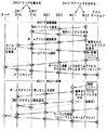
ィングテーブルR1〜R3を更新(書き換え)するようにすればよい。図17に、ルーティングテーブルR1〜R3を更新する場合の信号のやり取りを示す。
Therefore, in order to switch between the
最初に、通信システム1で通信を開始すると、移動端末20は、通信システム1を用いてゲートウェイGW1に通信システム1のIPアドレスを要求する。ゲートウェイGW1は第1実施形態と同様、DHCPサーバを兼ねているので、IPアドレスの要求に対し通信システム1のIPアドレスを移動端末20に付与する。これによって、移動端末20は、ルーティングテーブルR3を図16(a)に示すように更新する。
First, when communication is started in the
次に、移動端末20は、通信システム1を用いてゲートウェイGW1にルーティング情報(ルーティングテーブルR1、R2を図16(a)に示すように変更する指令)を伝達する。このルーティング情報は、さらに、ゲートウェイGW1からインターネットを介してゲートウェイGW2に伝達される。ゲートウェイGW1、GW2は、ルーティング情報によりルーティングテーブルR1、R2を、それぞれ図16(a)に示すように更新する。これらのルーティングテーブルR1〜R3を用いることにより、アプリケーションソフトによって、サーバと通信を行うことができる。
Next, the mobile terminal 20 transmits routing information (a command to change the routing tables R1 and R2 as shown in FIG. 16A) to the gateway GW1 using the
また、移動端末20が通信システム1から通信システム2に切り替えて通信を行うことになると、移動端末20は、通信システム2を用いてゲートウェイGW2にMS2のIPアドレスを要求する。ゲートウェイGW2は第1実施形態と同様、DHCPサーバを兼ねているので、IPアドレスの要求に対しMS2のIPアドレスを移動端末20に付与する。これによって、移動端末20は、ルーティングテーブルR3を図16(b)に示すように更新する。
When the mobile terminal 20 performs communication by switching from the
次に、移動端末20は、通信システム2を用いてゲートウェイGW2にルーティング情報(ルーティングテーブルR1、R2を図16(b)に示すように変更する指令)を伝達する。このルーティング情報は、さらに、ゲートウェイGW2からインターネットを介してゲートウェイGW1に伝達される。ゲートウェイGW1、GW2は、ルーティング情報によりルーティングテーブルR1、R2を、それぞれ図16(b)に示すように更新する。これらのルーティングテーブルR1〜R3を用いることにより、アプリケーションソフトによって、サーバと通信を行うことができる。 Next, the mobile terminal 20 transmits routing information (a command to change the routing tables R1 and R2 as shown in FIG. 16B) to the gateway GW2 using the communication system 2. This routing information is further transmitted from the gateway GW2 to the gateway GW1 via the Internet. The gateways GW1 and GW2 update the routing tables R1 and R2 with the routing information as shown in FIG. By using these routing tables R1 to R3, communication with the server can be performed by application software.
この実施形態によれば、通信システム1、2とアプリケーションソフトが動作する部分との間にルータ31を設け、アプリケーションソフトが通信システムとは異なる固有のサブネット(上記したサブネット3)のアドレスを持つことにより、同一の発信者アドレスで通信することができる。このため、モバイルIPによるトンネリングを用いなくとも、途絶えることなく通信システムの切り替えを行うことができる。また、IPトンネリングがないため、伝送のオーバヘッドがなく、効率の良い通信を行うことができる。
According to this embodiment, the
また、ルーティングテーブルR1〜R3を書き換えることにより、データの通信経路を通信システム1、2のいずれかに切り替えることができるため、通信システムの切り替えをスムーズに行うことができる。
Further, by rewriting the routing tables R1 to R3, the data communication path can be switched to any one of the
なお、この実施形態における制御部28は、上記したルーティングテーブルの書き換えを行う以外は、第1、第2実施形態と同様の制御処理を行う。具体的には、第1、第2実施形態において通信システム1、2で通信を実施する処理の部分が、この実施形態では、ルーティングテーブルR1〜R3を書き換える処理に変更される。
Note that the
なお、ルータ31としては、ルータ機能を持つ切り替え手段であれば、他の構成のものとしてもよい。
Note that the
また、この実施形態においても、第1、第2実施形態と同様、3つ以上の通信システムにも適用することができる。 This embodiment can also be applied to three or more communication systems as in the first and second embodiments.
また、上記した第1ないし第3実施形態において、移動端末を構成する各部は、それぞれの機能を実現する手段として把握されるものである。 Further, in the first to third embodiments described above, each unit constituting the mobile terminal is understood as a means for realizing each function.
20…移動端末、21a、21b…通信機、
22a、22b…インターフェース、23…通信システム切替部、
24…ネットワークドライバ、25…アプリケーション部、
26…受信電力モニタ、27…通信品質評価部、28…制御部、
29…ナビゲーションシステム、30…記憶媒体、31…ルータ。
20: mobile terminal, 21a, 21b: communication device,
22a, 22b interface, 23 communication system switching unit,
24: network driver, 25: application unit,
26: reception power monitor, 27: communication quality evaluation unit, 28: control unit,
29 navigation system, 30 storage medium, 31 router.
Claims (4)
各々の通信システムの基地局は、各通信システムごとにそれぞれ同一のサブネットワークに属し、各サブネットは各々に対して設けられたゲートウェイを介してインターネットに接続されており、前記各々のゲートウェイは、ルータ機能を有して前記インターネットと前記サブネットワーク間のルーティングを行うようになっており、
前記移動端末は、それぞれの通信システムにアクセス可能な複数の移動局ネットワークインターフェースを備え、前記複数の移動局ネットワークインターフェースとアプリケーションソフトが動作する部分との間にルータ機能を持つ切り替え手段を有して、前記アプリケーションソフトが動作する部分を前記複数の移動局ネットワークインターフェースのいずれか1つに接続して通信システムを切り替えるように構成され、前記アプリケーションソフトが、前記複数の通信システムとは異なる固有のサブネットのアドレスを持って同一の発信者アドレスで通信することを特徴とする無線通信システム。 A wireless communication system configured to communicate with a mobile terminal in a plurality of different communication systems,
The base station of each communication system belongs to the same sub-network for each communication system, and each subnet is connected to the Internet via a gateway provided for each communication system. Having a function to perform routing between the Internet and the sub-network,
The mobile terminal includes a plurality of mobile station network interfaces that can access respective communication systems, and has switching means having a router function between the plurality of mobile station network interfaces and a portion where application software operates. Connecting the part on which the application software operates to any one of the plurality of mobile station network interfaces to switch the communication system, wherein the application software has a unique subnet different from the plurality of communication systems. A wireless communication system characterized in that communication is performed with the same caller address having the same address.
前記複数の通信システムのそれぞれに対してアクセス可能な複数の移動局ネットワークインターフェースと、
前記複数の移動局ネットワークインターフェースとアプリケーションソフトが動作する部分との間にルータ機能を持つ切り替え手段とを有して、前記アプリケーションソフトが動作する部分を前記複数の移動局ネットワークインターフェースのいずれか1つに接続して通信システムを切り替えるように構成され、前記アプリケーションソフトが、前記複数の通信システムとは異なる固有のサブネットのアドレスを持って同一の発信者アドレスで通信することを特徴とする移動端末。 A mobile terminal used in the wireless communication system according to claim 1,
A plurality of mobile station network interfaces accessible to each of the plurality of communication systems;
A switching unit having a router function between the plurality of mobile station network interfaces and a portion on which application software operates, wherein a portion on which the application software operates is connected to any one of the plurality of mobile station network interfaces; A mobile terminal, wherein the application software communicates with the same caller address with a unique subnet address different from the plurality of communication systems.
Priority Applications (1)
| Application Number | Priority Date | Filing Date | Title |
|---|---|---|---|
| JP2004166876A JP2004304841A (en) | 2004-06-04 | 2004-06-04 | Radio communication system and mobile terminal used in radio communication system |
Applications Claiming Priority (1)
| Application Number | Priority Date | Filing Date | Title |
|---|---|---|---|
| JP2004166876A JP2004304841A (en) | 2004-06-04 | 2004-06-04 | Radio communication system and mobile terminal used in radio communication system |
Related Parent Applications (1)
| Application Number | Title | Priority Date | Filing Date |
|---|---|---|---|
| JP2000391124A Division JP3580250B2 (en) | 2000-12-22 | 2000-12-22 | Wireless communication system, network and mobile terminal used in wireless communication system |
Publications (1)
| Publication Number | Publication Date |
|---|---|
| JP2004304841A true JP2004304841A (en) | 2004-10-28 |
Family
ID=33411323
Family Applications (1)
| Application Number | Title | Priority Date | Filing Date |
|---|---|---|---|
| JP2004166876A Pending JP2004304841A (en) | 2004-06-04 | 2004-06-04 | Radio communication system and mobile terminal used in radio communication system |
Country Status (1)
| Country | Link |
|---|---|
| JP (1) | JP2004304841A (en) |
Cited By (9)
| Publication number | Priority date | Publication date | Assignee | Title |
|---|---|---|---|---|
| WO2006106846A1 (en) * | 2005-03-30 | 2006-10-12 | Matsushita Electric Industrial Co., Ltd. | Communication handover method and communication message processing method |
| JP2006333080A (en) * | 2005-05-26 | 2006-12-07 | Nec Corp | Portable communication terminal, communication route selection method and communication route selection program |
| JP2008522482A (en) * | 2004-12-20 | 2008-06-26 | 韓國電子通信研究院 | Heterogeneous network interworking method for nodes having multiple network interfaces |
| US7864755B2 (en) | 2005-02-01 | 2011-01-04 | Ntt Docomo, Inc. | Mobile node, base station, router and packet communication system that complies with an edge mobility scheme |
| JP4715750B2 (en) * | 2004-11-04 | 2011-07-06 | パナソニック株式会社 | Multi-interface communication device, terminal, and path switching method |
| JP2012085311A (en) * | 2005-09-19 | 2012-04-26 | Panasonic Corp | Method for enabling simultaneous use of foreign network and another network |
| JP2012222777A (en) * | 2011-04-14 | 2012-11-12 | Hitachi Ltd | Communication device and control method for handover |
| JP2014068209A (en) * | 2012-09-26 | 2014-04-17 | Fujitsu Semiconductor Ltd | Wireless station, semiconductor device, wireless communication system and control method thereof |
| JP2016187227A (en) * | 2016-08-01 | 2016-10-27 | 株式会社ソシオネクスト | Radio station, semiconductor device, radio communication system, and control method thereof |
-
2004
- 2004-06-04 JP JP2004166876A patent/JP2004304841A/en active Pending
Cited By (14)
| Publication number | Priority date | Publication date | Assignee | Title |
|---|---|---|---|---|
| JP4715750B2 (en) * | 2004-11-04 | 2011-07-06 | パナソニック株式会社 | Multi-interface communication device, terminal, and path switching method |
| JP2008522482A (en) * | 2004-12-20 | 2008-06-26 | 韓國電子通信研究院 | Heterogeneous network interworking method for nodes having multiple network interfaces |
| US7864755B2 (en) | 2005-02-01 | 2011-01-04 | Ntt Docomo, Inc. | Mobile node, base station, router and packet communication system that complies with an edge mobility scheme |
| JPWO2006106846A1 (en) * | 2005-03-30 | 2008-09-11 | 松下電器産業株式会社 | COMMUNICATION HANDOVER METHOD AND COMMUNICATION MESSAGE PROCESSING METHOD |
| WO2006106846A1 (en) * | 2005-03-30 | 2006-10-12 | Matsushita Electric Industrial Co., Ltd. | Communication handover method and communication message processing method |
| JP4617355B2 (en) * | 2005-03-30 | 2011-01-26 | パナソニック株式会社 | COMMUNICATION HANDOVER METHOD AND COMMUNICATION MESSAGE PROCESSING METHOD |
| US8009629B2 (en) | 2005-03-30 | 2011-08-30 | Panasonic Corporation | Communication handover method and communication message processing method |
| JP2006333080A (en) * | 2005-05-26 | 2006-12-07 | Nec Corp | Portable communication terminal, communication route selection method and communication route selection program |
| JP2012085311A (en) * | 2005-09-19 | 2012-04-26 | Panasonic Corp | Method for enabling simultaneous use of foreign network and another network |
| JP2012138913A (en) * | 2005-09-19 | 2012-07-19 | Panasonic Corp | Method for enabling simultaneous use of home network and foreign network by multihomed mobile node |
| JP2012222777A (en) * | 2011-04-14 | 2012-11-12 | Hitachi Ltd | Communication device and control method for handover |
| US8761845B2 (en) | 2011-04-14 | 2014-06-24 | Hitachi, Ltd. | Communication apparatus and handover control method |
| JP2014068209A (en) * | 2012-09-26 | 2014-04-17 | Fujitsu Semiconductor Ltd | Wireless station, semiconductor device, wireless communication system and control method thereof |
| JP2016187227A (en) * | 2016-08-01 | 2016-10-27 | 株式会社ソシオネクスト | Radio station, semiconductor device, radio communication system, and control method thereof |
Similar Documents
| Publication | Publication Date | Title |
|---|---|---|
| JP3580250B2 (en) | Wireless communication system, network and mobile terminal used in wireless communication system | |
| KR100939852B1 (en) | Distributed infrastructure for wireless data communications | |
| Perkins | Mobile networking in the Internet | |
| US7209480B2 (en) | Base station apparatus, mobile terminal apparatus and wireless access system using the apparatuses | |
| JP4615172B2 (en) | Cell communication system | |
| US8155041B2 (en) | Method for handover between heterogeneous networks using link trigger signal in multi-interface mobile router | |
| JP5166424B2 (en) | Systems and methods for using Internet mobility protocols with non-Internet mobility protocols | |
| US20090285184A1 (en) | Wireless communication system and mobile terminal | |
| US20020173303A1 (en) | Wireless communication system | |
| JP4032814B2 (en) | Communication terminal, router, terminal station, and fixed terminal | |
| KR20030089719A (en) | Distributed infrastructure for wireless data communications | |
| JP2004304841A (en) | Radio communication system and mobile terminal used in radio communication system | |
| JPWO2005053250A1 (en) | COMMUNICATION HANDOVER METHOD, COMMUNICATION MESSAGE PROCESSING METHOD, PROGRAM FOR EXECUTING THESE METHODS BY COMPUTER, AND COMMUNICATION SYSTEM | |
| JP4240411B2 (en) | Method and apparatus for providing address management in a flat structure mobile network | |
| JPWO2005043839A1 (en) | COMMUNICATION HANDOVER METHOD, COMMUNICATION HANDOVER PROGRAM, AND COMMUNICATION SYSTEM | |
| US20130322405A1 (en) | Method for supporting node mobility in wireless mesh network | |
| US20120163337A1 (en) | Method of allocating home network prefix, inter-handoff method, and multi-homing system thereof | |
| JP4425770B2 (en) | Mobile communication system, mobile unit, and mobile router | |
| CN113923593A (en) | An on-demand distributed edge node mobility management method | |
| KR100520513B1 (en) | Mobility support system for network mobility and method thereof | |
| WO2007066866A1 (en) | Routing optimization method | |
| KR100596383B1 (en) | Route Optimization Using Prefix Delegation Protocol | |
| KR100942703B1 (en) | Distributed Address Management Method for Guaranteeing Terminal Mobility in Network | |
| JP2011109594A (en) | Radio communication system | |
| JP5234366B2 (en) | Mobile communication system, mobility management apparatus, and mobility management control method |
Legal Events
| Date | Code | Title | Description |
|---|---|---|---|
| A977 | Report on retrieval |
Free format text: JAPANESE INTERMEDIATE CODE: A971007 Effective date: 20060104 |
|
| A131 | Notification of reasons for refusal |
Free format text: JAPANESE INTERMEDIATE CODE: A131 Effective date: 20060328 |
|
| A02 | Decision of refusal |
Free format text: JAPANESE INTERMEDIATE CODE: A02 Effective date: 20061010 |