JP2006200422A - Control device for automatic transmission - Google Patents
Control device for automatic transmission Download PDFInfo
- Publication number
- JP2006200422A JP2006200422A JP2005012187A JP2005012187A JP2006200422A JP 2006200422 A JP2006200422 A JP 2006200422A JP 2005012187 A JP2005012187 A JP 2005012187A JP 2005012187 A JP2005012187 A JP 2005012187A JP 2006200422 A JP2006200422 A JP 2006200422A
- Authority
- JP
- Japan
- Prior art keywords
- engine
- torque
- engagement
- pressure
- control
- Prior art date
- Legal status (The legal status is an assumption and is not a legal conclusion. Google has not performed a legal analysis and makes no representation as to the accuracy of the status listed.)
- Pending
Links
Images


Landscapes
- Control Of Driving Devices And Active Controlling Of Vehicle (AREA)
- Control Of Vehicle Engines Or Engines For Specific Uses (AREA)
- Control Of Transmission Device (AREA)
Abstract
Description
本発明は、アイドルストップ制御を備えた自動変速機の制御装置に関し、特にベルト式無段変速機の制御装置に関する。 The present invention relates to a control device for an automatic transmission having an idle stop control, and more particularly to a control device for a belt-type continuously variable transmission.
アイドルストップ制御を備えた自動変速機の制御装置として、特許文献1に記載の技術が開示されている。この公報には、エンジン再始動後のエンジン回転数が所定値以上になったことでプリチャージフェーズの終了を検出し、締結フェーズに移行することで発進クラッチの締結制御(所謂N−Dセレクト制御)を行っている。
ここで、発進クラッチに充填される油量は、ポンプ容積効率の回転数依存性や、各種バルブリークの大小による影響を受けるため、充填された油量を正確に予測することが難しい。また、充填された油量はオイルポンプやバルブ系の経時劣化に大幅に影響されるという問題がある。よって、特許文献1に記載の技術では、単にエンジン回転数によってプリチャージフェーズの終了を予測しただけでは、実際には十分に発進クラッチに油が充填されているかどうか疑わしい。一般に、N−Dセレクト制御時において、エンジンの回転数は、発進クラッチの締結が完了するまではアイドル回転数に保つ制御が行われる。この状態で発進クラッチの初期充填量が不十分のまま締結フェーズに入ると、締結が完了するまでに時間が掛かり、特に再始動後、すぐにアクセルペダルを踏み込み、全開発進した場合には、前進クラッチが急激に締結して、大きな発進ショックが発生するおそれがあった。 Here, the amount of oil charged in the starting clutch is affected by the rotational speed dependency of the pump volumetric efficiency and the size of various valve leaks, so it is difficult to accurately predict the amount of oil charged. Further, there is a problem that the amount of filled oil is greatly affected by deterioration with time of the oil pump and valve system. Therefore, in the technique described in Patent Document 1, it is doubtful whether the starting clutch is actually sufficiently filled with oil simply by predicting the end of the precharge phase based on the engine speed. In general, during ND selection control, the engine speed is controlled to be kept at an idle speed until the start clutch is completely engaged. In this state, if the initial phase of the starting clutch is insufficient and the engagement phase is entered, it will take time to complete the engagement, especially after restarting, when the accelerator pedal is depressed and all development progresses, it will move forward. There was a risk that the clutch would suddenly engage and a large starting shock would occur.
本発明は、上記問題に着目してなされたもので、アイドルストップ後のエンジン再始動時に、経時劣化等により十分な油量を確保できない場合であっても、違和感のない発進が可能な自動変速機の制御装置を提供することを目的とする。 The present invention has been made paying attention to the above-mentioned problem, and even when the engine is restarted after an idle stop, even when a sufficient amount of oil cannot be secured due to deterioration over time or the like, automatic transmission that can start without a sense of incongruity It is an object of the present invention to provide a control device for a machine.
上記目的を達成するため、本発明では、エンジンにより駆動されるオイルポンプと、車両発進時に前記オイルポンプを油圧源とする締結圧により締結される発進クラッチと、該発進クラッチの解放状態から締結状態に移行する際、締結圧制御を締結フェーズを経て行う締結圧制御手段と、車両停車時であって、かつ、所定の条件が成立したときはエンジンを停止し、前記所定の条件が不成立となったときはエンジンを再始動するアイドルストップ制御手段と、を備えた自動変速機の制御装置において、前記締結圧制御手段は、前記締結フェーズにおける前記発進クラッチの締結容量を上回らないようエンジンのトルクダウン指令をエンジンコントロールユニットに出力し、前記締結フェーズ終了後のタービン回転数と変速機入力軸回転数との差が所定値以上の場合、以降のエンジントルク制限量を所定値以上とするエンジンのトルクダウン指令を出力することとした。 To achieve the above object, according to the present invention, an oil pump driven by an engine, a starting clutch fastened by a fastening pressure using the oil pump as a hydraulic source when the vehicle starts, and a state in which the starting clutch is disengaged from a released state. And the fastening pressure control means for performing the fastening pressure control through the fastening phase, and when the vehicle is stopped and the predetermined condition is satisfied, the engine is stopped and the predetermined condition is not satisfied. And an idle stop control means for restarting the engine, wherein the engagement pressure control means reduces the engine torque so as not to exceed the engagement capacity of the starting clutch in the engagement phase. The command is output to the engine control unit, and the turbine rotational speed and transmission input shaft rotational speed after completion of the engagement phase are Is equal to or greater than the predetermined value, it was decided to output a torque-down command of the engine to a subsequent engine torque restriction rate to or larger than a predetermined value.
アイドルストップ後のエンジン再始動時に、発進クラッチに実際に充填される油量を精度良く推定でき、この油量に基づいて発進クラッチの締結制御を変更することで、クラッチ締結タイミングの遅れを防止することが可能となり、違和感のない発進を達成できる。 When the engine is restarted after idling stop, the amount of oil actually filled in the start clutch can be accurately estimated, and the start clutch engagement control is changed based on this amount of oil to prevent delay in clutch engagement timing. It is possible to achieve a start without a sense of incongruity.
以下、本発明の自動変速機の制御装置を実現する最良の形態を、図面に示す実施例に基づいて説明する。 DESCRIPTION OF THE PREFERRED EMBODIMENTS The best mode for realizing an automatic transmission control apparatus according to the present invention will be described below based on embodiments shown in the drawings.
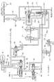
図1は実施例1におけるベルト式無段変速機3(以下CVTと記載する)を備えた自動変速機の制御系を表す図である。 FIG. 1 is a diagram illustrating a control system of an automatic transmission including a belt type continuously variable transmission 3 (hereinafter referred to as CVT) in the first embodiment.
1はトルクコンバータ、2はロックアップクラッチ、3はCVT、4はプライマリ回転数センサ、4aはタービン回転数センサ、5はセカンダリ回転数センサ、6は油圧コントロールバルブユニット、8はエンジンにより駆動されるオイルポンプ、9はCVTコントロールユニット、10はアクセル開度センサ、11は油温センサ、12はステアリングホイールの操舵角度を検出する舵角センサ、13はアイドルストップスイッチ、14は車速センサ、15はブレーキペダルのON・OFFを検出するブレーキスイッチ、16はライン圧を検出するライン圧センサ、17はアイドルストップコントロールユニット、18はエンジンコントロールユニット、19はエンジン、19aはスタータモータ、19bはエンジン出力軸である。 1 is a torque converter, 2 is a lock-up clutch, 3 is a CVT, 4 is a primary rotational speed sensor, 4a is a turbine rotational speed sensor, 5 is a secondary rotational speed sensor, 6 is a hydraulic control valve unit, and 8 is driven by an engine Oil pump, 9 is a CVT control unit, 10 is an accelerator opening sensor, 11 is an oil temperature sensor, 12 is a steering angle sensor that detects the steering angle of the steering wheel, 13 is an idle stop switch, 14 is a vehicle speed sensor, and 15 is a brake. Brake switch for detecting ON / OFF of pedal, 16 for line pressure sensor for detecting line pressure, 17 for idle stop control unit, 18 for engine control unit, 19 for engine, 19a for starter motor, 19b for engine output shaft is there.
エンジン出力軸19bには、オイルポンプ8と、回転伝達機構としてトルクコンバータ1が連結されるとともに、エンジン19とCVT3を直結するロックアップクラッチ2が備えられている。トルクコンバータ1の出力側にはタービンシャフト1aが接続され、このタービンシャフト1aは前後進切換機構20のリングギア21と連結されている。前後進切換機構20は、タービンシャフト1aと連結したリングギア21,ピニオンキャリア22,変速機入力軸1bと連結したサンギア23からなる遊星歯車機構から構成されている。ピニオンキャリア22には、変速機ケースにピニオンキャリア22を固定する後進ブレーキ24と、変速機入力軸1bとピニオンキャリア22を一体に連結する前進クラッチ25(発進クラッチ)が設けられている。
The
変速機入力軸1bの端部にはCVT3のプライマリプーリ30aが設けられている。CVT3は、上記プライマリプーリ30aとセカンダリプーリ30bと、プライマリプーリ30aの回転力をセカンダリプーリ30bに伝達するベルト34等からなっている。プライマリプーリ30aは、変速機入力軸1bと一体に回転する固定円錐板31と、固定円錐板31に対向配置されてV字状プーリ溝を形成するとともにプライマリプーリシリンダ室33に作用する油圧によって変速機入力軸1bの軸方向に移動可能である可動円錐板32からなっている。
A
セカンダリプーリ30bは、従動軸38上に設けられている。セカンダリプーリ30bは、従動軸38と一体に回転する固定円錐板35と、固定円錐板35に対向配置されてV字状プーリ溝を形成するとともにセカンダリプーリシリンダ室37に作用する油圧によって従動軸38の軸方向に移動可能である可動円錐板36とからなっている。
The
従動軸38には図示しない駆動ギアが固着されており、この駆動ギアはアイドラ軸に設けられたピニオン、ファイナルギア、差動装置を介して図外の車輪に至るドライブシャフトを駆動する。
A drive gear (not shown) is fixed to the driven
上記のようなCVT3にエンジン出力軸12から入力された回転力は、トルクコンバータ1及び前後進切換機構20を介して変速機入力軸1bに伝達される。変速機入力軸1bの回転力はプライマリプーリ30a,ベルト34,セカンダリプーリ30b,従動軸38,駆動ギア,アイドラギア,アイドラ軸,ピニオン,及びファイナルギアを介して差動装置に伝達される。
The rotational force input from the
上記のような動力伝達の際に、プライマリプーリ30aの可動円錐板32及びセカンダリプーリ30bの可動円錐板36を軸方向に移動させてベルト34との接触位置半径を変えることにより、プライマリプーリ30aとセカンダリプーリ30bとの間の回転比つまり変速比を変えることができる。このようなV字状のプーリ溝の幅を変化させる制御は、CVTコントロールユニット9を介してプライマリプーリシリンダ室33またはセカンダリプーリシリンダ室37への油圧制御により行われる。
During the power transmission as described above, by moving the movable
CVTコントロールユニット9には、タービン回転数センサ4aからのタービン回転数Nt、スロットル開度センサ10からのスロットル開度TVO、油温センサ11からの変速機内油温f、プライマリ回転数センサ4からのプライマリ回転数Npri、セカンダリ回転数センサ5からのセカンダリ回転数Nsec、ライン圧センサ16からのライン圧等が入力される。この入力信号を元に制御信号を演算し、油圧コントロールバルブユニット6へ制御信号を出力する。
The CVT control unit 9 includes a turbine rotational speed Nt from the turbine rotational speed sensor 4 a, a throttle opening TVO from the
油圧コントロールバルブユニット6へは、CVTコントロールユニット9からの制御信号が入力され、プライマリプーリシリンダ室33とセカンダリプーリシリンダ室37へ制御圧を供給することで変速制御を行う。
A control signal from the CVT control unit 9 is input to the hydraulic control valve unit 6, and shift control is performed by supplying control pressure to the primary
アイドルストップコントロールユニット17には、舵角センサ12、アイドルストップスイッチ13、車速センサ14、ブレーキスイッチ15からのセンサ信号が入力されるとともに、CVTコントロールユニット9と相互にセンサ信号やトルクダウン制御信号等を通信している。アイドルストップコントロールユニット17によりアイドルストップと判断されると、エンジンコントロールユニット18に対してアイドリングを停止する指令が出力される。
Sensor signals from the
また、アイドルストップ後のエンジン再始動と判断されると、エンジンコントロールユニット18に対してエンジン再始動指令が出力され、エンジンコントロールユニット18は、スタータモータ19aにモータ駆動信号を出力し、エンジン19を始動する。
If it is determined that the engine is restarted after the idle stop, an engine restart command is output to the
なお、アイドルストップコントロールユニット17から出力されるアイドルストップ指令等を、例えば、ブレーキユニットに設けられたヒルホールド制御部等に出力し、傾斜路面等でのアイドルストップ時に、車両の後退を防止するよう構成してもよい。また、再始動時には、前進クラッチ25の締結状態に応じたトルクダウン量が入力され、このトルクダウン量に応じたエンジン出力状態に制御するよう構成されている。
In addition, an idle stop command or the like output from the idle
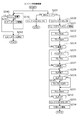
図2は実施例1におけるベルト式無段変速機の油圧回路を表す回路図である。プレッシャレギュレータバルブ40は油路8aから供給されたオイルポンプ8の吐出圧を、ライン圧(プーリクランプ圧)として調圧する。油路8aには油路8bが連通している。油路8bはCVT3のプライマリプーリシリンダ室33及びセカンダリプーリシリンダ室37に、ベルト34をクランプするプーリクランプ圧を供給するプーリクランプ圧供給油路である。また、油路8bに連通した油路8eは、パイロットバルブ50の元圧を供給する。
FIG. 2 is a circuit diagram illustrating a hydraulic circuit of the belt type continuously variable transmission according to the first embodiment. The
クラッチレギュレータバルブ45はプレッシャレギュレータバルブ40からドレンされた油圧を元圧として前進クラッチ圧を調圧する。プレッシャレギュレータバルブ40とクラッチレギュレータバルブ45は油路41を介して連通している。また、油路41には、ライン圧油路8cと連通するとともに、オリフィス8fを有する油路8dが連通している。また、油路41には、クラッチレギュレータバルブ45により調圧された油圧をセレクトスイッチングバルブ75及びセレクトコントロールバルブ90へ供給する油路42が連通している。
The
パイロットバルブ50は油路51を介してロックアップソレノイド71及びセレクトスイッチングソレノイド70への一定供給圧を設定する。セレクトスイッチングソレノイド70の出力圧は油路70aからセレクトスイッチングバルブ75に供給され、セレクトスイッチングバルブ75の作動を制御する。ロックアップソレノイド71の出力圧は油路71aからセレクトスイッチングバルブ75に供給される。
The
セレクトスイッチングソレノイド70の信号がONの状態では、ロックアップソレノイド71の信号圧は、セレクトスイッチングバルブ75を介してセレクトコントロールバルブ90の信号圧として作用する。また、セレクトスイッチングソレノイド70の信号がOFFされた状態では、ロックアップソレノイド71の信号圧は、セレクトスイッチングバルブ75を介して図外のロックアップコントロールバルブに導出される。
When the signal of the select switching
セレクトスイッチングソレノイド70の信号がゼロであって、ロックアップソレノイド71の信号もゼロの状態では、セレクトコントロールバルブ90への信号圧がゼロの状態となる。このとき、セレクトコントロールバルブ90のリターンスプリング91のバネ荷重によりスプールバルブ92を図中右方に移動させる。
When the signal of the select switching
プレッシャレギュレータバルブ40及びクラッチレギュレータバルブ45は、ともにプレッシャモディファイヤ圧によって調圧される。このプレッシャモディファイヤ圧は、ライン圧が供給されたプレッシャモディファイヤバルブ73をライン圧ソレノイド72によって調圧する信号圧であり、ソレノイド70,71,72による信号圧よりも高い信号圧として調圧する。
Both the
このソレノイド72による信号圧よりも高い信号圧により調圧することで、高圧領域における調圧性能の向上を図っている(第2締結手段に対応)。一方、ソレノイド71による信号圧によって調圧される圧は、低圧領域においてきめ細やかな調圧を可能としているが、調圧可能な最大圧は限られている(締結圧手段に対応)。
By adjusting the pressure with a signal pressure higher than the signal pressure by the
実施例1の前進クラッチ25締結制御にあっては、完全締結状態に移行してからの締結圧制御はクラッチレギュレータバルブ45によって行い、完全締結状態に移行する前の例えば発進時締結制御等にあっては、ロックアップソレノイド71による締結圧制御を実行する。前進クラッチ25解放状態から締結制御を行う際には、セレクトスイッチングソレノイド70をONとすることで、油路42と油路77を非連通状態とし、油路42の油圧はセレクトコントロールバルブ90を経由して油路77に供給されるよう構成する。同時に、ロックアップソレノイド71の信号圧は、図外のロックアップコントロールバルブとは非連通状態とし、セレクトコントロールバルブ90の対向圧として供給されるよう構成する。これにより、ロックアップソレノイド71の信号圧はセレクトコントロールバルブ90によって油路42の前進クラッチ25の締結圧を制御する。これにより、クラッチレギュレータバルブ45よりもきめ細かな締結圧制御が可能となる。
In the forward clutch 25 engagement control of the first embodiment, the engagement pressure control after shifting to the fully engaged state is performed by the
上記締結制御が終了すると、セレクトスイッチングソレノイド70及びロックアップソレノイド71をOFFとし、油路42と油路77を連通することで、前進クラッチ25の締結圧はクラッチレギュレータバルブ45で調圧された締結圧がそのまま供給されるものとする。実施例1では、上述したように前進クラッチ25の締結制御を切り換える構成を、元圧切換タイプと定義する。
When the above engagement control is completed, the
図3は実施例1におけるアイドルストップ制御の基本制御内容を表すフローチャートである。 FIG. 3 is a flowchart showing the basic control contents of the idle stop control in the first embodiment.
ステップ101では、アイドルストップ許可フラグがONで、アイドルストップスイッチが通電、車速が0、ブレーキスイッチがON、舵角が0かどうか等を判断し、全ての条件を満たしたときのみステップ102へ進み、それ以外はアイドルストップ制御を無視する。
In
ステップ102では、セレクト位置が走行レンジかどうかを判定し、走行レンジであればステップ103へ進み、それ以外はステップ104へ進む。
In
ステップ103では、油温Toilが下限油温Tlowよりも温度が高く上限油温Thiよりも低いかどうかを判定し、条件を満たしていればステップ104へ進み、それ以外はステップ101へ進む。
In
ステップ104では、エンジン10を停止する。
In
ステップ105では、ブレーキスイッチ2がOFFかどうかを判定し、OFF状態であればステップ106へ進む。
In
ステップ106では、エンジン再始動制御を実行する。
In
すなわち、運転者がアイドルストップ制御を希望しており、車両が停止状態で、ブレーキが踏まれており、舵角が0あれば、エンジンを停止する。ここで、アイドルストップスイッチは、運転者がアイドルストップを実行又は解除する意志を伝えるものである。イグニッションキーを回した時点でこのスイッチは通電状態である。また、舵角が0の場合としたのは、例えば右折時等の走行時の一時停車時においては、アイドルストップを禁止するためである。 That is, if the driver desires idle stop control, the vehicle is stopped, the brake is depressed, and the steering angle is 0, the engine is stopped. Here, the idle stop switch conveys the intention of the driver to execute or cancel the idle stop. This switch is energized when the ignition key is turned. The reason why the rudder angle is 0 is that, for example, idle stop is prohibited when the vehicle is temporarily stopped during traveling such as when turning right.
なお、アイドルストップ許可フラグとは、他の制御ロジック等によって設定され、アイドルストップを行ったとしても、好ましくないエンジン再始動制御が達成できないような場合に設定される。具体的には、後述する前進クラッチ25の締結制御がうまくいかない場合や、バッテリの充電量不足によりスタータモータ19aを駆動できない場合等が挙げられるが特に限定しない。
The idle stop permission flag is set by other control logic or the like, and is set when undesirable engine restart control cannot be achieved even when idle stop is performed. Specific examples include a case where the engagement control of the forward clutch 25 described later is not successful, and a case where the
次に、油温Toilが下限油温Tlowよりも高く、上限油温Thiよりも低いかどうかを判定する。これは、油温が所定温度以上でないと、油の粘性抵抗のために、エンジン完爆前に所定油量の充填ができない可能性があるためである。また、油温が高温状態では、粘性抵抗の低下によりオイルポンプ8の容積効率が低下することと、バルブ各部のリーク量が増加するため、同様にエンジン完爆前に締結要素への所定油量が充填できない可能性があるためである。
Next, it is determined whether the oil temperature Toil is higher than the lower limit oil temperature Tlow and lower than the upper limit oil temperature Thi. This is because if the oil temperature is not equal to or higher than the predetermined temperature, there is a possibility that the predetermined amount of oil cannot be filled before the engine complete explosion due to the viscous resistance of the oil. In addition, when the oil temperature is high, the volumetric efficiency of the
次に、ブレーキが離されたときは、運転者にエンジン始動の意志があると判断し、また、ブレーキが踏まれた状態であっても、アイドルストップスイッチに非通電が確認されるときは、運転者にエンジン始動の意志があると判断する。これは、例えばアイドルストップによりエンジンを停止すると、バッテリに負担がかかり、エアコン等の使用ができないといった事が生じないように、運転者が車室内の温度を暑いと感じたときには、運転者の意志によってアイドルストップ制御を解除することができることで、より運転者の意図に沿った制御を実行できるように構成されているものである。 Next, when the brake is released, it is determined that the driver is willing to start the engine, and even when the brake is stepped on, when it is confirmed that the idle stop switch is not energized, It is determined that the driver is willing to start the engine. This is because, for example, when the driver feels that the temperature in the passenger compartment is hot, the battery will be overloaded and the air conditioner cannot be used when the engine is stopped due to idle stop. Thus, the idle stop control can be canceled by the control so that the control more in line with the driver's intention can be executed.
運転者にエンジン始動の意志があると判断したときは、スタータモータ19aを作動することでエンジンを再始動する。
When it is determined that the driver intends to start the engine, the engine is restarted by operating the
エンジン停止時はオイルポンプ8が停止した状態であるため、前進クラッチ25及びCVT3の各プーリシリンダ室33,37に供給されている油も油路から抜け、油圧が低下してしまう。そのため、エンジンが再始動されるときには、前進クラッチ25もその係合状態が解かれてしまった状態となっているため、エンジン再始動時に油圧を供給する必要がある。なお、各プーリシリンダ室33,37に貯留された油は、アイドルストップ時間が短いときにはさほど抜けることはなく、ある程度の油量が確保されており、長時間停車した場合には徐々に油が抜けるよう構成されている。
Since the
[エンジン再始動制御]
次に、前進クラッチ締結制御について説明する。基本的に、前進クラッチ25を締結するときは、クラッチプレートのガタや皿ばね等を押し潰し、クラッチピストンストロークが終了するまでの状態をプリチャージフェーズと定義し、クラッチピストンストロークが終了した状態を締結フェーズと定義する。締結フェーズ終了後未だクラッチプレートのスリップ状態が解消されない状態を締結終了フェーズと定義し、クラッチプレートのスリップが解消され、完全締結に移行する状態を完全締結フェーズと定義する。
[Engine restart control]
Next, forward clutch engagement control will be described. Basically, when the
[エンジン再始動制御処理]
図4は、アイドルストップコントロールユニット17において実行されるエンジン再始動制御の流れを示すフローチャートである。以下、各ステップSについて説明する。
[Engine restart control processing]
FIG. 4 is a flowchart showing a flow of engine restart control executed in the idle
ステップS200では、セレクト位置が走行レンジかどうかを判別し、YESであればステップS220へ移行し、NOであればステップS210へ移行する。 In step S200, it is determined whether or not the select position is the travel range. If YES, the process proceeds to step S220, and if NO, the process proceeds to step S210.
<スタータモータ駆動制御処理>
ステップS240〜S242では、スタータモータの駆動制御処理の流れを示す。
<Starter motor drive control processing>
Steps S240 to S242 show the flow of starter motor drive control processing.
ステップS240では、エンジンが完爆したかどうかが判断され、YESであればステップS242へ移行し、NOであればステップS241へ移行する。なお、完爆判定は、エンジン回転数が所定回転数以上かどうかを判定すればよく特に限定しない。 In step S240, it is determined whether or not the engine has completely exploded. If YES, the process proceeds to step S242, and if NO, the process proceeds to step S241. The complete explosion determination is not particularly limited as long as it is determined whether the engine speed is equal to or higher than a predetermined speed.
ステップS241では、スタータモータを駆動し、ステップS240へ戻る。 In step S241, the starter motor is driven, and the process returns to step S240.
ステップS242では、スタータモータを停止し、制御を終了する。 In step S242, the starter motor is stopped and the control is terminated.
<前進クラッチ締結状態判断制御処理>
ステップS220〜S218までは、前進クラッチ25の締結状態がプリチャージフェーズ、締結フェーズ、及び締結終了フェーズのいずれに相当するかを判断する制御処理の流れを示す。
<Forward clutch engagement state judgment control process>
Steps S220 to S218 show the flow of control processing for determining whether the engaged state of the
ステップS210では、セレクトスイッチングソレノイド70をONとし、制御を終了する。
In step S210, the
<トルクダウン制御処理>
ステップS220〜S234では、前進クラッチの締結状態に応じたエンジントルクダウン制御処理の流れを示す。
<Torque down control processing>
Steps S220 to S234 show the flow of the engine torque down control process according to the engaged state of the forward clutch.
ステップS220では、セレクトスイッチングソレノイド70をONとし、ステップS221へ移行する。
In step S220, the
ステップS221では、フェーズタイマによりエンジン始動からの時間計測を開始し、ステップS222へ移行する。 In step S221, time measurement from the engine start is started by the phase timer, and the process proceeds to step S222.
(プリチャージフェーズ)
ステップS222では、前進クラッチ締結圧指令値Pccをプリチャージフェーズにおける締結指令値Ppreとし、ステップS223へ移行する。
(Precharge phase)
In step S222, the forward clutch engagement pressure command value Pcc is set to the engagement command value Ppre in the precharge phase, and the process proceeds to step S223.
ステップS223では、トルクダウン指令値TDをプリチャージフェーズにおけるトルクダウン指令値Tdpreとし、ステップS224へ移行する。 In step S223, the torque-down command value TD is set as the torque-down command value Tdpre in the precharge phase, and the process proceeds to step S224.
ステップS224では、プリチャージフェーズ時間Tpが経過したかどうかが判断され、YESであればステップS225へ移行して締結フェーズにおけるトルクダウン制御を実行し、NOであればステップS222へ戻る。 In step S224, it is determined whether or not the precharge phase time Tp has elapsed. If YES, the process proceeds to step S225 to execute torque reduction control in the engagement phase, and if NO, the process returns to step S222.
(締結フェーズ)
ステップS225では、前進クラッチ締結圧指令値Pccを棚圧進行速度がVpとなる圧P(Vp)とし、ステップS226へ移行する。
(Conclusion phase)
In step S225, the forward clutch engagement pressure command value Pcc is set to a pressure P (Vp) at which the shelf pressure advancement speed becomes Vp, and the process proceeds to step S226.
ステップS226では、トルクダウン指令値TDを締結フェーズにおけるトルクダウン指令値TDsとし、ステップS227へ移行する。 In step S226, the torque-down command value TD is set as the torque-down command value TDs in the engagement phase, and the process proceeds to step S227.
ステップS227では、締結フェーズ時間Tsが経過したかどうかが判断され、YESであればステップS228のスリップ判断へ移行し、NOであればステップS225へ戻る。 In step S227, it is determined whether the engagement phase time Ts has elapsed. If YES, the process proceeds to slip determination in step S228, and if NO, the process returns to step S225.
(締結フェーズにおける前進クラッチスリップ判断及びスリップ低減制御)
ステップS228では、タービンシャフト1aと変速機入力軸1bとの回転数差SLIPを演算し、ステップS229へ移行する。
(Forward clutch slip judgment and slip reduction control in the engagement phase)
In step S228, the rotational speed difference SLIP between the turbine shaft 1a and the
ステップS229では、ステップS228で演算した回転数差SLIPが所定値を超過するかどうかが判断され、YESであればステップS230へ移行し、NOであればステップS231へ移行する。 In step S229, it is determined whether or not the rotational speed difference SLIP calculated in step S228 exceeds a predetermined value. If YES, the process proceeds to step S230, and if NO, the process proceeds to step S231.
ステップS230では、前進クラッチ25のスリップ解消のためトルクダウン指令値TDをを締結フェーズにおけるトルクダウン量TDsよりも大きいTDL(SLIP)とし、ステップS231に移行する。TDL(SLIP)の設定は、図5に示すSLIP-TDL(SLIP)マップに基づき、ステップS208で演算されたSLIPに対応する値を読み込む。
In step S230, the torque-down command value TD is set to TDL (SLIP) larger than the torque-down amount TDs in the engagement phase to eliminate the slip of the
ステップS231では、前進クラッチ締結圧指令値Pccを締結終了フェーズにおける締結指令値Pendとし、ステップS232とする。 In step S231, the forward clutch engagement pressure command value Pcc is set as the engagement command value Pend in the engagement end phase, and step S232 is set.
ステップS232では、回転数差SLIPが0かどうかが判断され、YESであればステップS233へ移行し、NOであればステップS228へ戻る。 In step S232, it is determined whether the rotational speed difference SLIP is 0. If YES, the process proceeds to step S233, and if NO, the process returns to step S228.
(締結終了フェーズ)
ステップS233では、セレクトスイッチングソレノイド70をOFFとし、ステップS234へ移行する。
(Conclusion end phase)
In step S233, the
ステップS234では、トルクダウン指令値TDを徐々に解除し、制御を終了する。 In step S234, the torque-down command value TD is gradually released and the control is terminated.
[前進クラッチ締結処理及びトルクダウン量設定処理の作用]
次に、上記フローチャートに基づく作用について説明する。エンジン再始動指令が出力されると、ステップS240〜ステップS242においてスタータモータ19aを駆動し、エンジン19を始動する。この動作に並行して、アクセルペダルがONかどうかが判定される。
[Operation of forward clutch engagement processing and torque down amount setting processing]
Next, the operation based on the flowchart will be described. When the engine restart command is output, the
アクセルペダルが踏み込まれていなければ、エンジン19はアイドル回転数を維持するため大きなトルクが出力されることはない。したがって、通常のタイマ管理に基づくプリチャージフェーズ→締結フェーズ→締結終了フェーズへと移行し、前進クラッチ25を締結する。
If the accelerator pedal is not depressed, a large torque is not output because the
一方、アクセルペダルが踏み込まれているときは、アクセル開度に応じてエンジン出力トルクが増大する。ここで、前進クラッチ25の締結に必要な油圧が十分に確保されていない場合は、エンジン19からの入力トルクが大きくなると前進クラッチスリップ状態が長時間継続していまい、クラッチプレートの劣化や発進応答遅れを招く。
On the other hand, when the accelerator pedal is depressed, the engine output torque increases according to the accelerator opening. Here, when the hydraulic pressure necessary for engaging the
したがって、アクセルペダルが踏み込まれたときは、エンジンコントロールユニット18に対しトルクダウン量TDを出力し、前進クラッチ25への入力トルクを制限する。以下、トルクダウン量設定論理につき説明する。
Therefore, when the accelerator pedal is depressed, the torque reduction amount TD is output to the
[トルクダウン量設定]
実施例1の自動変速機にあっては、エンジン出力軸19bの出力トルクはトルクコンバータ1により増幅され、変速機入力軸1bを駆動する。ここで、前進クラッチ25への入力トルク制御はタービンシャフト1aのトルクを制御することにより達成される。タービントルクTtは前進クラッチ25の締結容量によって決定されるため、前進クラッチ25への締結圧指令値からタービントルクTt(Pcc)を推定する。
[Torque down amount setting]
In the automatic transmission according to the first embodiment, the output torque of the
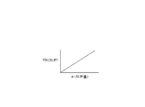
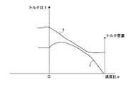
図7は、トルクコンバータ1における速度比eとトルク比tとの関係を示す図である。ここで、タービン回転数をNt、エンジン回転数をNe、タービントルクをTt、エンジントルクをTeとすると
速度比e=Nt/Ne トルク比t=Tt/Te
の関係から、タービントルクTtを出力する目標エンジントルクTe*は
Te*=(1/t)・Tt(Pcc)
となる。
FIG. 7 is a diagram illustrating the relationship between the speed ratio e and the torque ratio t in the torque converter 1. Here, if the turbine speed is Nt, the engine speed is Ne, the turbine torque is Tt, and the engine torque is Te, the speed ratio e = Nt / Ne Torque ratio t = Tt / Te
Therefore, the target engine torque Te * that outputs the turbine torque Tt is
Te * = (1 / t) ・ Tt (Pcc)
It becomes.
ここで、前進クラッチ25が締結していない状態においてエンジンを再始動すると、タービンシャフト1aにかかるイナーシャは自身のイナーシャのみであるため、タービンシャフト1aはエンジン出力により連れ回り、タービン回転数Ntは増大してしまう。この状態で速度比eをエンジン回転数Neとタービン回転数Ntの比として計算すると、速度比eは非常に大きな値となり、これに伴ってトルク比tは小さな値となる。
Here, when the engine is restarted in a state where the
すなわち、タービントルクTtに対する目標エンジントルクTe*が大きくなるに伴ってトルクダウン量も小さくなり、エンジンが吹け上がり気味となる。そこで、実施例1のトルクダウン制御量演算処理ではタービン回転数Ntではなくプライマリ回転数Npriを用いてトルクダウン量を演算する。プライマリ回転数Npriは車両負荷に従属する値であるため、精度のよいトルクダウン量を演算することができる。以下、上記論理に基づくトルクダウン量設定制御処理について説明する。 That is, as the target engine torque Te * with respect to the turbine torque Tt increases, the torque reduction amount also decreases, and the engine feels like being blown up. Therefore, in the torque-down control amount calculation process of the first embodiment, the torque-down amount is calculated using the primary rotation speed Npri instead of the turbine rotation speed Nt. Since the primary rotational speed Npri is a value dependent on the vehicle load, an accurate torque reduction amount can be calculated. Hereinafter, torque down amount setting control processing based on the above logic will be described.
[トルクダウン量設定制御処理]
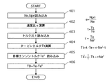
図6は、トルクダウン量設定制御処理の流れを示すフローチャートである。
ステップS401では、エンジン回転数Neとプライマリ回転数Npriを読み込む。
[Torque down amount setting control processing]
FIG. 6 is a flowchart showing the flow of torque down amount setting control processing.
In step S401, the engine speed Ne and the primary speed Npri are read.
ステップS402では、速度比e=Npri/Neを読み込む。 In step S402, the speed ratio e = Npri / Ne is read.
ステップS403では、図7に示す速度比−トルク比マップからトルク比t(=Tt/Te)を読み込む。 In step S403, the torque ratio t (= Tt / Te) is read from the speed ratio-torque ratio map shown in FIG.
ステップS404では、前進クラッチ締結圧指令値Pccに対応するタービントルク推定値Tt(Pcc)を演算する。 In step S404, a turbine torque estimated value Tt (Pcc) corresponding to the forward clutch engagement pressure command value Pcc is calculated.
ステップS405では、各フェーズにおけるタービントルク推定値Tt(Pcc)を読み込み、このタービントルク推定値Tt(Pcc)とトルク比tに基づいて目標エンジントルクTe*を演算し、エンジンコントロールユニット18に出力する。トルクコンバータ1の特性によってトルク比tは決定されており、前進クラッチ締結圧指令値Pccによってタービントルク推定値Tt(Pcc)も決定できるため、速度比eによって目標エンジントルクTe*を演算することができる。この目標エンジントルクTe*が前進クラッチ締結制御における各フェーズにおいて最適な入力トルクとなるようにトルクダウン量を設定する。
In step S405, the estimated turbine torque value Tt (Pcc) in each phase is read, the target engine torque Te * is calculated based on the estimated turbine torque value Tt (Pcc) and the torque ratio t, and is output to the
ステップS406では、実エンジントルクTeと目標エンジントルクTe*の差分Te-Te*を演算し、この差分Te-Te*をトルクダウン量TDとしてエンジンのトルクダウン制御を行う。 In step S406, the difference Te-Te * between the actual engine torque Te and the target engine torque Te * is calculated, and the engine torque-down control is performed using the difference Te-Te * as the torque-down amount TD.
[基準時間Ts超過時トルクダウン制御の経時変化]
図8は、締結フェーズの時間が基準時間Tsを超過した場合におけるトルクダウン制御の経時変化を示すタイムチャートである。
[Change over time in torque-down control when the reference time Ts is exceeded]
FIG. 8 is a time chart showing the change over time of the torque-down control when the time of the engagement phase exceeds the reference time Ts.
(時刻t1)
時刻t1において運転者によりブレーキがOFFとされ、再発進準備のため前進クラッチ25に作動油の供給が開始され、クラッチプレートのガタ詰めすなわちピストンストロークを行うプリチャージフェーズが開始する。
(Time t1)
The brake is turned off by the driver at time t1, the supply of hydraulic oil to the
(時刻t1〜t2)
時刻t1〜t2においてアクセルがONとされ、その直後にセカンダリプーリ圧が上昇を開始する。このとき前進クラッチ25はプリチャージフェーズであり、エンジントルクTeを入力してもトルク伝達はほとんど行われないため、トルクダウン制御によりエンジントルクTeは抑制され、上昇しない。
(Time t1 to t2)
At time t1 to t2, the accelerator is turned on, and immediately after that, the secondary pulley pressure starts to rise. At this time, the
(時刻t2)
時刻t2において前進クラッチ25のピストン室における実圧が上昇を開始する。このとき、セカンダリプーリの油圧は上昇を継続する。
(Time t2)
At time t2, the actual pressure in the piston chamber of the forward clutch 25 starts to rise. At this time, the hydraulic pressure of the secondary pulley continues to rise.
(時刻t2〜t3)
時刻t2〜t3において前進クラッチ25の実圧が上昇を開始するが、指令圧には到達しない。時刻t3まではプリチャージフェーズが継続するためエンジントルクは上昇しない。一方、セカンダリプーリ圧は目標圧に達し一定圧となり、以降も一定圧を継続する。
(Time t2 to t3)
At times t2 to t3, the actual pressure of the forward clutch 25 starts to rise, but does not reach the command pressure. Until the time t3, the precharge phase continues, so the engine torque does not increase. On the other hand, the secondary pulley pressure reaches the target pressure and becomes a constant pressure, and the constant pressure is continued thereafter.
(時刻t3)
時刻t3において前進クラッチ25のピストンストロークが終了し、クラッチプレートのスリップ状態が開始される締結フェーズに移行する。これに伴い、前進クラッチ25の実圧が指令圧に達し、前進クラッチ25の伝達可能トルクが上昇を開始する。締結フェーズに移行したことで、トルクダウン制御により締結フェーズに対応するトルクダウン指令が出力され、エンジンのトルクダウン量は前進クラッチ25の伝達可能トルクを上回らないよう抑制されつつ上昇を開始する。
(Time t3)
At time t3, the piston stroke of the forward clutch 25 ends and the clutch phase shifts to an engagement phase where the clutch plate starts to slip. Accordingly, the actual pressure of the
(時刻t4)
時刻t4において締結フェーズ開始からの計測時間が基準時間Tsに到達する。しかし、クラッチプレートのスリップは未だ解消しておらず、完全締結には移行せず締結終了フェーズに移行する。クラッチプレートのスリップを速やかに解消するため、時刻t4〜t5における締結終了フェーズではエンジンのトルクダウン量を増加させ、時刻t3〜t4における締結フェーズにおけるトルクダウン量よりも大きいものとする。これによりエンジントルクTeは下降し、タービン回転数Ntすなわち前進クラッチ25の駆動側回転数と、プライマリ回転数Niすなわち前進クラッチ25の出力側回転数の差ΔNは徐々に減少し、クラッチプレートのスリップが徐々に解消する。
(Time t4)
At time t4, the measurement time from the start of the fastening phase reaches the reference time Ts. However, the slip of the clutch plate has not yet been resolved, and the shift to the engagement end phase is made without shifting to the complete engagement. In order to quickly eliminate the clutch plate slip, the torque reduction amount of the engine is increased in the engagement end phase at times t4 to t5, and is larger than the torque reduction amount in the engagement phase at times t3 to t4. As a result, the engine torque Te decreases, and the difference ΔN between the turbine rotational speed Nt, that is, the drive-side rotational speed of the
(時刻t5)
時刻t5においてクラッチプレートのスリップが解消し、前進クラッチ25の完全締結が可能な完全締結フェーズに移行する。前進クラッチ25の指令圧を元圧として締結圧を元圧とするとともに、エンジンのトルクダウン指令を解除する。
(Time t5)
At time t5, the clutch plate slip is eliminated, and the phase shifts to a complete engagement phase in which the forward clutch 25 can be completely engaged. The command pressure of the
(時刻t6)
時刻t6においてエンジントルクが最大となる。
(Time t6)
The engine torque becomes maximum at time t6.
[実施例1の作用効果]
実施例1では、アイドルストップ後の再発進時において、前進クラッチ25の締結容量を上回らないようエンジントルクの制御を行い、前進クラッチ25の締結フェーズ終了後のタービン回転数Ntと変速機入力軸回転数Npriとの差が所定値以上の場合、以降のトルクダウン量TDL(SLIP)を締結フェーズにおけるトルクダウン量TDsよりも大きいものとする。これにより、アイドルストップ後のエンジン再始動時に、経時劣化等により十分な油量を確保できない場合であっても、違和感のない再発進を可能とすることができる。
[Effects of Example 1]
In the first embodiment, the engine torque is controlled so as not to exceed the engagement capacity of the forward clutch 25 during the restart after the idle stop, and the turbine rotational speed Nt and the transmission input shaft rotation after the engagement phase of the forward clutch 25 ends. When the difference from the number Npri is equal to or greater than a predetermined value, the subsequent torque down amount TDL (SLIP) is assumed to be larger than the torque down amount TDs in the engagement phase. Thus, even when the sufficient amount of oil cannot be ensured due to deterioration over time when the engine is restarted after idling stop, it is possible to make it possible to restart without a sense of incongruity.
また、締結終了フェーズにおけるエンジンのトルクダウン量TDL(SLIP)を締結フェーズの終了時におけるトルクダウン量TDs以上としたとき、前進クラッチ25の駆動側と従動側のクラッチプレートの回転数差、すなわちタービン回転数Ntとプライマリ回転数Niの差ΔNを演算し、この回転数差ΔNに基づいて徐々にトルクダウン量TDL(SLIP)を増加させることとした。これにより、締結フェーズ終了後前進クラッチ25のスリップが存在する場合であっても、徐々にクラッチプレートのスリップを解消することで、急激なクラッチ締結を回避して円滑な発進を行うことができる。
Further, when the engine torque-down amount TDL (SLIP) in the engagement end phase is equal to or greater than the torque-down amount TDs at the end of the engagement phase, the difference in the rotational speed between the drive plate and the driven-side clutch plate of the
低圧領域のみ調圧可能な手段であるロックアップソレノイド71、セレクトスイッチングソレノイド70、セレクトスイッチングバルブ75およびセレクトコントロールバルブ90によりエンジン再始動の締結圧制御を行うとともに、締結完了後は低圧領域よりも高い高圧領域のみ調圧可能な第2締結圧手段であるクラッチレギュレータバルブ45、プレッシャモディファイヤバルブ73、ライン圧ソレノイド72を設け、前進クラッチ25を完全締結した後は、クラッチレギュレータバルブ45による締結圧制御に切り換える。その際、トルクダウン量を徐々に減少させ、エンジンのトルクが一定量に達した後はトルクダウンを解除することとした。これにより、急激にエンジントルクが入力されることがなく、ベルト式無段変速機のベルトすべり等を防止できる。
The
(他の実施例)
以上、本発明を実施するための最良の形態を実施例1に基づいて説明してきたが、本発明の具体的な構成は各実施例に限定されるものではなく、発明の要旨を逸脱しない範囲の設計変更等があっても、本発明に含まれる。
(Other examples)
As described above, the best mode for carrying out the present invention has been described based on the first embodiment. However, the specific configuration of the present invention is not limited to each embodiment, and does not depart from the gist of the present invention. Such design changes are included in the present invention.
3 ベルト式無段変速機
4 プライマリ回転数センサ
5 セカンダリ回転数センサ
6 油圧コントロールバルブユニット
8 オイルポンプ
9 コントロールユニット
10 エンジン
13 アイドルストップスイッチ
16 ライン圧センサ
17 アイドルストップコントロールユニット
18 エンジンコントロールユニット
19 エンジン
19b エンジン出力軸
25 前進クラッチ
33 プライマリプーリシリンダ室
40 プレッシャレギュレータバルブ
45 クラッチレギュレータバルブ
50 パイロットバルブ
70 セレクトスイッチングソレノイド
71 ロックアップソレノイド
72 ライン圧ソレノイド
73 プレッシャモディファイヤバルブ
75 セレクトスイッチングバルブ
83 プレッシャモディファイヤバルブ
90 セレクトコントロールバルブ
3 Belt type continuously variable transmission 4 Primary rotational speed sensor 5 Secondary rotational speed sensor 6 Hydraulic
Claims (2)
車両発進時に前記オイルポンプを油圧源とする締結圧により締結される発進クラッチと、
該発進クラッチの解放状態から締結状態に移行する際、締結圧制御を締結フェーズを経て行う締結圧制御手段と、
車両停車時であって、かつ、所定の条件が成立したときはエンジンを停止し、前記所定の条件が不成立となったときはエンジンを再始動するアイドルストップ制御手段と、
を備えた自動変速機の制御装置において、
前記締結圧制御手段は、前記締結フェーズにおける前記発進クラッチの締結容量を上回らないようエンジンのトルクダウン指令をエンジンコントロールユニットに出力し、
前記締結フェーズ終了後のタービン回転数と変速機入力軸回転数との差が所定値以上の場合、以降のエンジントルク制限量を所定値以上とするエンジンのトルクダウン指令を出力すること
を特徴とする自動変速機の制御装置。 An oil pump driven by an engine;
A starting clutch fastened by a fastening pressure using the oil pump as a hydraulic source when the vehicle starts,
An engagement pressure control means for performing an engagement pressure control through an engagement phase when shifting from the released state of the starting clutch to the engaged state;
An idle stop control means for stopping the engine when the vehicle is stopped and when a predetermined condition is satisfied, and restarting the engine when the predetermined condition is not satisfied;
In an automatic transmission control device comprising:
The engagement pressure control means outputs an engine torque down command to the engine control unit so as not to exceed the engagement capacity of the start clutch in the engagement phase.
When the difference between the turbine rotational speed after the end of the engagement phase and the transmission input shaft rotational speed is equal to or greater than a predetermined value, an engine torque down command for outputting a subsequent engine torque limit amount equal to or greater than the predetermined value is output. Automatic transmission control device.
前記締結圧制御手段は、前記エンジンのトルク制限量を前記所定値以上としたとき、前記発進クラッチの駆動側と従動側の回転数差を演算し、この回転数差に基づいて徐々に前記エンジントルク制限量を増加させるトルクダウン指令をエンジンコントロールユニットに出力すること
を特徴とする自動変速機の制御装置。
The control apparatus for an automatic transmission according to claim 1,
The fastening pressure control means calculates a rotational speed difference between the driving side and the driven side of the start clutch when the torque limit amount of the engine is greater than or equal to the predetermined value, and gradually increases the engine based on the rotational speed difference. A control device for an automatic transmission, wherein a torque down command for increasing a torque limit amount is output to an engine control unit.
Priority Applications (1)
| Application Number | Priority Date | Filing Date | Title |
|---|---|---|---|
| JP2005012187A JP2006200422A (en) | 2005-01-20 | 2005-01-20 | Control device for automatic transmission |
Applications Claiming Priority (1)
| Application Number | Priority Date | Filing Date | Title |
|---|---|---|---|
| JP2005012187A JP2006200422A (en) | 2005-01-20 | 2005-01-20 | Control device for automatic transmission |
Publications (1)
| Publication Number | Publication Date |
|---|---|
| JP2006200422A true JP2006200422A (en) | 2006-08-03 |
Family
ID=36958642
Family Applications (1)
| Application Number | Title | Priority Date | Filing Date |
|---|---|---|---|
| JP2005012187A Pending JP2006200422A (en) | 2005-01-20 | 2005-01-20 | Control device for automatic transmission |
Country Status (1)
| Country | Link |
|---|---|
| JP (1) | JP2006200422A (en) |
Cited By (10)
| Publication number | Priority date | Publication date | Assignee | Title |
|---|---|---|---|---|
| KR100833614B1 (en) | 2007-06-28 | 2008-05-30 | 주식회사 케피코 | Engine control method of vehicle with idle stop function |
| JP2008150022A (en) * | 2006-12-15 | 2008-07-03 | Hyundai Motor Co Ltd | Engine torque control method for hybrid electric vehicle equipped with ETC |
| JP2008208988A (en) * | 2007-01-31 | 2008-09-11 | Yamaha Motor Co Ltd | VEHICLE, ITS CONTROL DEVICE AND VEHICLE ABNORMALITY DETECTION |
| JP2009030680A (en) * | 2007-07-25 | 2009-02-12 | Nissan Motor Co Ltd | Vehicle start clutch standby control device |
| JP2009092207A (en) * | 2007-10-11 | 2009-04-30 | Honda Motor Co Ltd | Control device for continuously variable transmission |
| JP2017036744A (en) * | 2015-08-06 | 2017-02-16 | トヨタ自動車株式会社 | Vehicle control device |
| CN106481810A (en) * | 2015-09-02 | 2017-03-08 | 丰田自动车株式会社 | Controller of vehicle and control method for vehicle |
| CN110703589A (en) * | 2019-10-18 | 2020-01-17 | 上海格陆博实业有限公司 | Lower-layer controller control strategy based on double PID control algorithm |
| CN112937583A (en) * | 2021-03-19 | 2021-06-11 | 重庆长安汽车股份有限公司 | Vehicle low-temperature starting control method and computer-storable medium |
| WO2023276776A1 (en) * | 2021-07-02 | 2023-01-05 | ジヤトコ株式会社 | Vehicle control device, vehicle control method, and program |
-
2005
- 2005-01-20 JP JP2005012187A patent/JP2006200422A/en active Pending
Cited By (16)
| Publication number | Priority date | Publication date | Assignee | Title |
|---|---|---|---|---|
| JP2008150022A (en) * | 2006-12-15 | 2008-07-03 | Hyundai Motor Co Ltd | Engine torque control method for hybrid electric vehicle equipped with ETC |
| JP2008208988A (en) * | 2007-01-31 | 2008-09-11 | Yamaha Motor Co Ltd | VEHICLE, ITS CONTROL DEVICE AND VEHICLE ABNORMALITY DETECTION |
| KR100833614B1 (en) | 2007-06-28 | 2008-05-30 | 주식회사 케피코 | Engine control method of vehicle with idle stop function |
| WO2009002002A1 (en) * | 2007-06-28 | 2008-12-31 | Kefico Corporation | Engine control method for a vehicle with idle stop function |
| US8214112B2 (en) | 2007-06-28 | 2012-07-03 | Kefico Corporation | Engine control method for a vehicle with idle stop function |
| JP2009030680A (en) * | 2007-07-25 | 2009-02-12 | Nissan Motor Co Ltd | Vehicle start clutch standby control device |
| JP2009092207A (en) * | 2007-10-11 | 2009-04-30 | Honda Motor Co Ltd | Control device for continuously variable transmission |
| JP2017036744A (en) * | 2015-08-06 | 2017-02-16 | トヨタ自動車株式会社 | Vehicle control device |
| CN106481810A (en) * | 2015-09-02 | 2017-03-08 | 丰田自动车株式会社 | Controller of vehicle and control method for vehicle |
| JP2017048864A (en) * | 2015-09-02 | 2017-03-09 | トヨタ自動車株式会社 | Vehicle control device |
| CN110703589A (en) * | 2019-10-18 | 2020-01-17 | 上海格陆博实业有限公司 | Lower-layer controller control strategy based on double PID control algorithm |
| CN110703589B (en) * | 2019-10-18 | 2023-11-03 | 上海格陆博实业有限公司 | Lower controller control strategy based on double PID control algorithm |
| CN112937583A (en) * | 2021-03-19 | 2021-06-11 | 重庆长安汽车股份有限公司 | Vehicle low-temperature starting control method and computer-storable medium |
| CN112937583B (en) * | 2021-03-19 | 2022-06-03 | 重庆长安汽车股份有限公司 | Vehicle low-temperature starting control method and computer-storable medium |
| WO2023276776A1 (en) * | 2021-07-02 | 2023-01-05 | ジヤトコ株式会社 | Vehicle control device, vehicle control method, and program |
| JP7545586B2 (en) | 2021-07-02 | 2024-09-04 | ジヤトコ株式会社 | Vehicle control device, vehicle control method, and program |
Similar Documents
| Publication | Publication Date | Title |
|---|---|---|
| JP4129264B2 (en) | Control device for automatic transmission | |
| JP4319151B2 (en) | Control device for automatic transmission | |
| JP3964333B2 (en) | Automatic transmission gear shifting hydraulic system | |
| JP4784563B2 (en) | Control device for lock-up clutch | |
| JP4006257B2 (en) | Automatic transmission gear shifting hydraulic system | |
| JP2006200422A (en) | Control device for automatic transmission | |
| JP2003294118A (en) | Transmission hydraulic system for automatic transmission | |
| JP4417237B2 (en) | Control device for automatic transmission | |
| JP2004125037A (en) | Transmission control device for continuously variable transmission | |
| JP2005036820A (en) | Transmission hydraulic control device for idle stop vehicle | |
| JP4452228B2 (en) | Line pressure control device for continuously variable transmission | |
| JP4573796B2 (en) | Hydraulic control device for automatic transmission | |
| JP4319128B2 (en) | Control device for automatic transmission | |
| JP4070739B2 (en) | Continuously variable transmission | |
| JP2009101910A (en) | Vehicle control device | |
| JP5712331B2 (en) | Engine automatic stop vehicle and control method thereof | |
| JP4645119B2 (en) | Control device for continuously variable transmission | |
| JP2007071300A (en) | Control device for automatic transmission | |
| JP6268409B2 (en) | Control device for idle stop car | |
| JPWO2019044397A1 (en) | Vehicle control device and vehicle control method | |
| JP2004124969A (en) | Lock-up controller for automatic transmission | |
| JP2008106813A (en) | Hydraulic control device of belt continuously variable transmission for vehicle | |
| JP2008106812A (en) | Hydraulic control device of belt continuously variable transmission for vehicle | |
| JP2018150970A (en) | Automatic transmission and control method of automatic transmission | |
| JP2018013174A (en) | Controller of automatic transmission and control method of automatic transmission |
Legal Events
| Date | Code | Title | Description |
|---|---|---|---|
| A621 | Written request for application examination |
Free format text: JAPANESE INTERMEDIATE CODE: A621 Effective date: 20060607 |
|
| A131 | Notification of reasons for refusal |
Free format text: JAPANESE INTERMEDIATE CODE: A131 Effective date: 20080902 |
|
| A02 | Decision of refusal |
Free format text: JAPANESE INTERMEDIATE CODE: A02 Effective date: 20090106 |