JP2008196617A - Pipe structure and method for expanding and contracting the pipe structure - Google Patents
Pipe structure and method for expanding and contracting the pipe structure Download PDFInfo
- Publication number
- JP2008196617A JP2008196617A JP2007033127A JP2007033127A JP2008196617A JP 2008196617 A JP2008196617 A JP 2008196617A JP 2007033127 A JP2007033127 A JP 2007033127A JP 2007033127 A JP2007033127 A JP 2007033127A JP 2008196617 A JP2008196617 A JP 2008196617A
- Authority
- JP
- Japan
- Prior art keywords
- pipe
- pressure
- pipe member
- members
- seal mechanism
- Prior art date
- Legal status (The legal status is an assumption and is not a legal conclusion. Google has not performed a legal analysis and makes no representation as to the accuracy of the status listed.)
- Pending
Links
- 238000000034 method Methods 0.000 title claims description 17
- 230000007246 mechanism Effects 0.000 claims abstract description 60
- 239000000463 material Substances 0.000 claims abstract description 18
- 239000002184 metal Substances 0.000 claims abstract description 7
- 238000007789 sealing Methods 0.000 claims description 16
- 230000008602 contraction Effects 0.000 claims description 4
- 230000008569 process Effects 0.000 claims description 4
- 238000010276 construction Methods 0.000 claims description 2
- 238000007599 discharging Methods 0.000 claims description 2
- 238000010586 diagram Methods 0.000 description 7
- 238000004378 air conditioning Methods 0.000 description 5
- 238000001514 detection method Methods 0.000 description 4
- 239000012530 fluid Substances 0.000 description 4
- 238000007689 inspection Methods 0.000 description 4
- 238000012856 packing Methods 0.000 description 4
- 238000005096 rolling process Methods 0.000 description 4
- 230000000694 effects Effects 0.000 description 3
- 230000008439 repair process Effects 0.000 description 3
- 230000005494 condensation Effects 0.000 description 2
- 238000009833 condensation Methods 0.000 description 2
- 230000007423 decrease Effects 0.000 description 2
- 238000009434 installation Methods 0.000 description 2
- 230000002093 peripheral effect Effects 0.000 description 2
- XLYOFNOQVPJJNP-UHFFFAOYSA-N water Substances O XLYOFNOQVPJJNP-UHFFFAOYSA-N 0.000 description 2
- BZHJMEDXRYGGRV-UHFFFAOYSA-N Vinyl chloride Chemical compound ClC=C BZHJMEDXRYGGRV-UHFFFAOYSA-N 0.000 description 1
- 239000000853 adhesive Substances 0.000 description 1
- 230000001070 adhesive effect Effects 0.000 description 1
- 238000007664 blowing Methods 0.000 description 1
- 238000001816 cooling Methods 0.000 description 1
- 238000009826 distribution Methods 0.000 description 1
- 239000000428 dust Substances 0.000 description 1
- 239000000446 fuel Substances 0.000 description 1
- 238000010438 heat treatment Methods 0.000 description 1
- 238000012423 maintenance Methods 0.000 description 1
- 238000004519 manufacturing process Methods 0.000 description 1
- 239000003973 paint Substances 0.000 description 1
- 230000009467 reduction Effects 0.000 description 1
- 238000009423 ventilation Methods 0.000 description 1
Images


Landscapes
- Joints Allowing Movement (AREA)
Abstract
【課題】
金属やFRP製等の剛性の管路部材を、移動可能な構造物に支持材によって取付けた場合でも管路部材が移動する構造物に追従して伸縮、移動し、且つ管路部材内を流れる気体が漏洩しないように気密性を維持することができるようにした管路構造を提供することにある。
【解決手段】
移動可能な構造体に支持材によって取付けられた大きさの異なる少なくとも2つの管路部材を伸縮可能に相互に嵌め込み、一方の管路部材内に嵌め込まれた他方の管路部材の端部外周に外方に拡張可能なシール機構を設けると共に、構造体の移動に追従して該一方の管路部材を移動可能に支持する車輪部材を設けたことを特徴とする管路構造。
【選択図】 図1【Task】
Even when a rigid pipe member made of metal, FRP, or the like is attached to a movable structure by a support material, the pipe member follows the structure to which the pipe member moves, expands and contracts, and flows in the pipe member. An object of the present invention is to provide a pipeline structure that can maintain airtightness so that gas does not leak.
[Solution]
At least two pipe members of different sizes attached to a movable structure by a support material are fitted into each other in a stretchable manner, and the outer periphery of the end of the other pipe member fitted into one pipe member A pipe structure characterized by providing a seal mechanism that can be expanded outward and a wheel member that movably supports the one pipe member following the movement of the structure.
[Selection] Figure 1
Description
本発明は、移動可能な構造体に設置した角形または丸形の風路と呼称されるダクト等の管路構造および管路構造を伸縮する方法、特に大きさの異なるダクトを伸縮可能に嵌め込んだ管路構造およびこのような管路構造を伸縮する方法に関するものである。 The present invention relates to a pipe structure such as a duct called a square or round air passage installed in a movable structure, and a method for expanding and contracting the pipe structure, and in particular, fitting ducts of different sizes in a telescopic manner. The present invention relates to a pipe structure and a method for expanding and contracting such a pipe structure.
従来、事務所、工場建物内の剛性の空調用、換気用のダクト、または工場プラント用の金属製や塩化ビニール製の剛性のダクトは、天井、壁等の固定の構造物に単に支持材により固定されただけのものである。 Conventionally, rigid air-conditioning and ventilation ducts in offices and factory buildings, or rigid ducts made of metal or vinyl chloride for factory plants, are simply supported on a fixed structure such as a ceiling or wall. It is only fixed.
また、ダクトは、必ずしも天井や壁等の固定の構造物だけに支持材によって固定されたものだけではなく、空港施設や港湾施設の乗客乗降用搭乗橋や乗客乗降用連絡橋のような可動の構造物にも支持材によって取付けられている。
上述するように、従来技術に係るダクトのような剛性の管路は、天井、壁等の不動の構造物だけに支持材により固定されるだけでなく、移動する構造物に支持材によって固定される場合もある。 As described above, rigid ducts such as ducts according to the prior art are not only fixed to a stationary structure such as a ceiling and a wall by a support material, but also fixed to a moving structure by a support material. There is also a case.
このために、従来はフレキシブルな機能を持った柔軟な管路を使用していた。フレキシブルな管路として、上記特許文献1に記載されるようにフレキシブルダクトを用いるものがある。
For this purpose, a flexible conduit having a flexible function has been conventionally used. As a flexible pipe line, there is one using a flexible duct as described in
しかしながら、特許文献1に示されるダクトは、ダクト自体がフレキシブルな機能を有した柔軟な構造のダクトであり、このようなフレキシブルダクトを、移動する構造物に使用すると、構造物の移動によってフレキシブルダクトが撓んで弛むので、送風した場合に弛みによってフレキシブルダクト内の抵抗が増加したり、空気の流れによって想定できない動きをフレキシブルダクトが生じ、柔軟なフレキシブルダクト自体や、周囲の構造物を損傷することがある。また、ダクトの弛みは、外観の意匠上も違和感を生じるものである。
However, the duct shown in
また、従来においては、空気調和器からの空気を地下に埋設した管路構造に送風し、航空機に供給していたが、点検、修理および交換が極めて困難な状況にある。更に、海の埋立造成地に建設された海上空港での地盤沈下による埋設ダクトの破損に対する修復は極めて困難であり、航空機への空気調和設備が備わっていない既存飛行場での埋設管路部材の施工も航空機駐機場の非常に厚いコンクリート、多量の鉄筋および複雑に埋設配置された航空機用燃料配管、電線用電気配管等により極めて困難である。また、公共交通手段としての一定期間の駐機場閉鎖の困難性もあり、従来の埋設管路方式では対応が不可能に近い状態にある。 In the past, air from an air conditioner was blown to a pipeline structure buried underground and supplied to an aircraft. However, inspection, repair, and replacement are extremely difficult. Furthermore, it is extremely difficult to repair buried ducts due to land subsidence at the offshore airport constructed in the landfill site of the sea, and construction of buried pipe members at existing airfields that do not have air conditioning equipment for aircraft. However, it is extremely difficult due to the extremely thick concrete, a large amount of rebar, aircraft fuel pipes, and electric pipes for electric wires, etc. In addition, it is difficult to close the parking area for a certain period as a public transportation means, and it is almost impossible to cope with the conventional buried pipeline system.
本発明は、このような点に鑑みて成されたものであり、その目的は、金属やFRP製等の剛性の管路部材を、移動する構造物に支持材によって取付けた場合でも管路部材が移動する構造物に追従して伸縮、移動し、且つ管路部材内を流れる空気のような気体が漏洩しないように気密性を維持することができるようにした伸縮可能な管路構造、および管路構造の伸縮方法を提供することにある。 The present invention has been made in view of the above points, and its purpose is to provide a duct member even when a rigid duct member made of metal or FRP is attached to a moving structure with a support material. An expandable / contractible duct structure that expands and contracts following a moving structure, and that can maintain hermeticity so that a gas such as air flowing in the duct member does not leak, and The object is to provide a method for expanding and contracting a pipe structure.
上述の目的を解決するために本発明の管路構造は、移動可能な構造体に支持材によって取付けられた大きさの異なる少なくとも2つの管路部材を伸縮可能に相互に嵌め込み、一方の管路部材内に嵌め込まれた他方の管路部材の端部外周に外方に拡張可能なシール機構を設けると共に、構造体の移動に追従して該他方の管路部材を移動可能に支持する車輪部材を設けたことを特徴とする。 In order to solve the above-described object, the pipe structure of the present invention is configured such that at least two pipe members of different sizes attached to a movable structure by a support member are fitted to each other so as to be extendable and contracted. A wheel member that provides an outwardly expandable seal mechanism on the outer periphery of the other pipe member fitted in the member and that supports the other pipe member movably following the movement of the structure. Is provided.
また、本発明の管路構造は、車輪部材が、前記他方の管路部材の端部下方側または前記一方の管路部材の端部内方側に少なくとも1つ取付けられたキャスターであることを特徴とする。更に、本発明の管路構造は、管路部材が、金属またはFRP製の種々な大きさの円形または角形の管路部材であることを特徴とする。更にまた、本発明の管路構造は、シール機構が、管路部材を取り囲む環状の弾性部材を有し、圧力空気の供給、排出で弾性部材を拡張、収縮して両管路部材間をシールすることを特徴とする。本発明の管路構造は、構造物の移動の際の管路部材の伸縮終了時に、送風機の吹出し口直近の圧力空気を管部材で導いてシール機構の弾性部材を拡張して、一方の管路部材の内壁に密着させて両管路部材間からの圧力空気の漏洩を防ぎ、構造物の移動開始時には拡張された弾性部材内の圧力空気を排出して管路部材を伸縮できるようにしたことを特徴とする。 In the pipe structure of the present invention, at least one wheel member is a caster attached to the lower side of the end of the other pipe member or the inner side of the end of the one pipe member. And Furthermore, the pipe structure of the present invention is characterized in that the pipe member is a circular or square pipe member of various sizes made of metal or FRP. Furthermore, in the pipe structure of the present invention, the sealing mechanism has an annular elastic member surrounding the pipe member, and the elastic member is expanded and contracted by supply and discharge of pressure air to seal between the two pipe members. It is characterized by doing. In the pipe structure of the present invention, at the end of expansion and contraction of the pipe member during the movement of the structure, the pressure member in the vicinity of the blower outlet of the blower is guided by the pipe member to expand the elastic member of the seal mechanism. Closed to the inner wall of the path member to prevent leakage of pressurized air from between the two pipe members, and at the start of movement of the structure, the compressed air in the expanded elastic member is discharged so that the pipe member can be expanded and contracted It is characterized by that.
本発明の管路構造を伸縮する方法は、伸縮可能に相互に嵌め込んだ大きさの異なる少なくとも2つの管路部材の一方の管路部材の端部外周に外方に拡張可能に設けたシール機構と、前記一方の管路部材を移動可能に支持するように設けた車輪部材と、送風機、複数個の自動開閉弁および制御盤を有する加圧配管回路とを備えた管路構造を伸縮する方法において、送風機を作動して管路部材に送風する工程と、送風機出口の圧力と管路部材内の圧力とを圧力センサーで測定して圧力差を差圧検知器で検知する工程と、圧力差が所定の数値以上の時に、圧力空気の一部をシール機構に供給して拡張して両管路部材の間をシールする工程と、から成ることを特徴とする。また、本発明の管路構造を伸縮する方法は、上記圧力差が所定の数値以下の時には、補助加圧源として加圧発生装置によって圧力空気の供給を補助してシール機構を拡張してシールを補助する工程を、更に有することを特徴とする。更に、本発明の管路構造を伸縮する方法は、構造物の移動を要する時には、送風機の運転を停止し、自動開閉弁の1つを開いて外気と連通してシール機構内の圧力を減圧して管路部材からシール機構を離す工程を有することを特徴とする。 The method for expanding and contracting the conduit structure of the present invention is a seal provided on the outer periphery of the end of one of the at least two conduit members of different sizes fitted to each other so as to be expandable outwardly. Extending and contracting a pipeline structure comprising a mechanism, a wheel member provided to movably support the one pipeline member, and a pressurized piping circuit having a blower, a plurality of automatic opening / closing valves and a control panel In the method, the step of operating the blower to blow air to the pipe member, the step of measuring the pressure at the blower outlet and the pressure in the pipe member with a pressure sensor and detecting the pressure difference with the differential pressure detector, And a step of supplying a part of the pressurized air to the sealing mechanism and expanding it to seal between the two pipe members when the difference is equal to or greater than a predetermined value. Further, the method for expanding and contracting the pipe structure of the present invention is such that when the pressure difference is less than or equal to a predetermined value, the seal mechanism is expanded by assisting the supply of pressurized air as an auxiliary pressurizing source by a pressurizing generator. It further has the process of assisting. Further, according to the method for expanding and contracting the pipe structure of the present invention, when the structure needs to be moved, the operation of the blower is stopped, and one of the automatic open / close valves is opened to communicate with the outside air to reduce the pressure in the seal mechanism. And a step of separating the seal mechanism from the pipe member.
本発明によれば、金属、FRP製、またはそれらの組合せ合成体の管路部材を移動する構造物に支持材により取付けた場合でも、キャスターのような移動車輪によって管路部材が移動する構造物に追従して滑らかに伸縮、移動し、且つ気体の圧力によって伸縮、拡張するシール機構を設けることにより、管路部材内を流れる気体が漏洩しないようにように気密性を維持することができる。また、圧力源としての送風機の吹出し直後の気体圧力の一部を利用することにより、省エネルギー化を図ることができると共に、圧力源の圧力が減少した時でも圧力ボンベ、または加圧発生装置によるバックアップによってシール機構を加圧、拡張し、管路部材内を流れる気体の漏洩を確実に防止することができる。また、移動用車輪部材としてのキャスターおよびシール機構の弾性部材の容易な点検、交換ができるようにフランジ固定手段を採用している。 According to the present invention, a structure in which a pipe member is moved by a moving wheel such as a caster even when the pipe member made of metal, FRP, or a combination thereof is attached to a moving structure by a support material. By providing a seal mechanism that smoothly expands and contracts following and moves, and expands and contracts by gas pressure, the airtightness can be maintained so that the gas flowing in the pipe member does not leak. In addition, it is possible to save energy by using a part of the gas pressure immediately after the blower blows out as a pressure source, and to back up by a pressure cylinder or a pressure generator even when the pressure of the pressure source decreases. Thus, the sealing mechanism can be pressurized and expanded to reliably prevent leakage of the gas flowing in the pipe member. Further, a flange fixing means is employed so that the caster as the moving wheel member and the elastic member of the seal mechanism can be easily inspected and replaced.
このような伸縮形の管路部材によって、例えば飛行場のターミナルビルと航空機とを継ぎ、航空機の機種によって管路部材の伸縮、且つ左右への移動によって乗客を乗降させる搭乗橋に支持材によって管路部材を取付け、空調設備からの圧力空気を、航空機に夏場は冷風を、冬場には温風を夫々送風することによって冷暖房することができ、今後の飛行場旅客サービスといった観点からも極めて有効である。 By such a telescopic pipe member, for example, a terminal building of an airfield and an aircraft are connected, and a pipe line is formed by a support material on a boarding bridge on which passengers get on and off by expanding and contracting the pipe member depending on the type of aircraft and moving to the left and right. It is possible to cool and heat the air by installing members, and sending air pressure from the air conditioning equipment to the aircraft in the summer and cool air in the summer, and warm air in the winter, which is extremely effective from the viewpoint of airfield passenger service in the future.
以下に、本発明の実施形態を図面に基づいて詳細に説明する。なお、本発明を丸形の管路部材を有する管路構造について以下に説明するが、丸形の管路部材に限られることなく、三角形や四角形等の多角形、或いは長方形のような管路部材を有する管路構造にも適用できることは勿論である。 Embodiments of the present invention will be described below in detail with reference to the drawings. In addition, although this invention is demonstrated below about the pipe structure which has a round pipe line member, it is not restricted to a round pipe member, Polygons, such as a triangle and a rectangle, or a pipe line like a rectangle Of course, the present invention can also be applied to a pipe line structure having members.
図1乃至図4は、本発明の1つの実施の形態に係り、例として横断面円形の管路構造を示しており、図1は、縦断面図、図2は、右側面図、図3は、左側面図、図4は、シール部の加圧配管回路系統図、図5は、制御フローチャート図である。図6および図7は、伸縮型の管路構造のシール部、キャスター等の点検、交換をする時の要領図で、図6は、一方の管路部材を点検、交換可能な位置に移動した時の図で、図7は、交換するために他方の管路部材を取外した時の図である。 FIG. 1 to FIG. 4 relate to one embodiment of the present invention, and show a pipe structure having a circular cross section as an example, FIG. 1 is a longitudinal sectional view, FIG. 2 is a right side view, FIG. Fig. 4 is a left side view, Fig. 4 is a pressurization piping circuit diagram of a seal portion, and Fig. 5 is a control flowchart. 6 and 7 are schematic diagrams for inspecting and exchanging the seal part and casters of the telescopic pipe structure. FIG. 6 shows that one of the pipe members has been moved to a position where it can be inspected and replaced. FIG. 7 is a view when the other pipe member is removed for replacement.
図1乃至図3に示すように、本発明の管路構造1は、金属、FRP製、またはそれらの組合せ合成体等の複数個の、図示実施例では2つの、直径の異なる大小の剛性の管路部材2、4を望遠鏡筒状に嵌め合わせて成り、これら管路部材2、4の間にシール部5と、移動可能に支持するキャスター6とが設けられている。キャスター6は、図示実施例では自重による管路部材4の重量を支持するためにコロやローラ部材等の転動部材として図2に示されるように下方側に2つ設けられている。勿論、キャスター6は1つだけでも良く、重量の配分を考慮して左右に2つに分けて配置するのが好適である。また、キャスター6は、大径の管路部材2Aの端部内方側に設けることもできる。
As shown in FIG. 1 to FIG. 3, the
本発明での管路構造1は、管路部材2、4を移動可能な搭乗橋のような構造物の外壁に適宜な支持材によって取付けられており、小径の管路部材4に取付けられたキャスター6によって剛性の管路構造1が移動する構造物に追従して滑らかに伸縮、移動し、且つ気体の圧力によって伸縮、拡張するシール機構5を設けることによって、管路構造1内を流れる圧力空気のような気体が管路部材2、4間から漏洩しないように気密性を維持することができる。
The
また、シール機構5を、加圧源として、通常は送風機の吹出し直後の圧力を利用することにより、省エネルギー化を図ることができると共に、圧力源の圧力が減少した時でも圧力ボンベ、または加圧発生装置によるバックアップによってシール機構5を加圧、拡張して、管路構造1内を流れる気体の管路部材2、4間からの漏洩を確実に防止することができる。また、シール機構5とキャスター6の容易な点検、補修および交換ができるようにフランジ固定手段を採用している。更に、剛性の管路構造1の管路部材2、4の外表面の結露水、雨水、付着物の除去装置としてブラシ状またはゴム板状の閉鎖板部材3を設けることによって、管路構造1内への水分や塵埃の侵入防止を図ることが可能となる。
Further, by using the
このような伸縮形の管路構造1を、例えば飛行場のターミナルビルと航空機を継ぎ、機種によって伸縮、且つ左右への移動によって乗客を乗降させる搭乗橋を構造物として、この搭乗橋に支持材によって取付け、空調施設からの空調用気体を航空機に、夏場には冷風として、冬場には温風として夫々送風することによって冷暖房することができるように構成されている。
Such a
図1に示されるように、本発明の管路構造1の大小の異径の管路部材2、4は、各管路部材2、4の端部に、構造物の移動に伴って伸縮可能に且つ気密にシールするように構成された接続構造10を有している。このような管路部材2、4における接続構造10は、大径の管路部材2の端部に小区分として設けられた管路部材2Aと、この管路部材2A内に嵌合されて管路部材2Aとの間に環状の間隙Sを置いて配置された小径の管路部材4の小区分として形成された管路部材4Aとから形成されている。大径の管路部材2Aは、管路部材2の端部のフランジ部2aに対応するフランジ部12を介して一端が接続されており、他端はブラシ状やゴム板状の閉鎖板部材3によって閉じられている。また、小径の管路部材4Aは、大径の管路部材2内に開口する端部が自由端部として開口しており、他端にフランジ部16が設けられていて、このフランジ部16が、管路部材4の端部のフランジ部18に接続されている。また、これらフランジ部16、18の間には適宜なパッキン17が好適に設けられている。
As shown in FIG. 1, the
管路構造1が伸縮できるように外径の小さい剛性の管路部材4にキャスター6のような車輪部材を取付けると共に、移動、伸縮終了時に送風機によってこの剛性の管路構造1内に気体を流す時に送風機の吹出し口直近の圧力をホースのような管部材7で導き、小径の管路部材4に取付けた弾力性のあるゴムのような弾性部材8を拡張して、大径の管路部材2の内壁に密着させることによって気体の漏洩を防ぐと共に、管路構造1の移動、伸縮開始時には拡張された弾力性のあるゴムのような弾性部材8内の圧力を排出することができるシール機構5を形成している。
A wheel member such as a
また、必要に応じてはキャスター6のような移動車輪と、シール性を保持させる弾力性のあるシール機構5の弾性部材8の修理を可能とする共に、交換を容易にする構造としている。更に、剛性の管路部材4の表面に付着した結露水、雨水、付着異物の管路部材2内への侵入を防止するために、ブラシ状の部材や、弾力性を持ったゴム板のような弾性部材から閉鎖板部材3を、管路部材2Aの端部に除去装置として取外し自在に取付けていることを特徴としている。
Further, if necessary, it is possible to repair the moving wheel such as the
図1の拡大部分図に示されるようにシール機構5は、管路部材4の端部の管路部材4Aの外表面上に溝形部材のような環状部材14を有している。この環状部材14は、外周面が溝形の環状を成していて、管路部材4Aの外周面上に適宜な接着剤によって接着されて固着されており、外方に向かって開口した環状の溝部15を有している。さらに、この環状部材14の外方に向かって開口した環状の溝部15には、ゴムのような弾性部材8が取付けられており、弾性部材8により覆われた溝部15内に管部材7を介して圧力空気のような圧力気体が供給され、これによって弾性部材8が拡張されて管路部材2Aの内壁面に対して密着されてシールするようになっている。
As shown in the enlarged partial view of FIG. 1, the
また、環状部材14の溝部14内への圧力気体の供給が停止されて排出されるようになると、環状部材14の溝部15内が減圧されて弾性部材8が内側に凹んで弾性部材8が管路部材2Aの内壁面から離れるので、管路部材2、4を構造物の移動に伴って移動することができ、弾性部材8の表面を何ら損傷することがなく、良好に管路部材2、2A、4、4Aを構造物と共に移動することができる。
Further, when the supply of the pressure gas into the
このような管路部材2、2A、4、4Aの構造物と一緒の移動を容易にするために、例えば、管路部材4Aの移動用の車輪部材としてのキャスター6が、小径の管路部材4の重量に基づいて、図2に示されるように管路部材4の下側に複数台のキャスター6が好適に取付けられている。
In order to facilitate movement together with the structure of
このようなキャスター6は、図2の拡大部分図に示されるようにキャスター部材を形成するコロやローラのような転動部材22と、この転動部材22を回転可能に左右両側から支承する一対の支承部材24とから構成されており、支承部材24を管路部材4Aの表面上に取付けるために管路部材4Aの内側から宛がわれる取付部材25とを有し、ねじやボルト26によって取付けられている。
As shown in the enlarged partial view of FIG. 2, the
また、伸縮可能な管路部材2、2A、4、4Aが伸縮、移動して、ある位置で停止し且つ送風機によって圧力気体を流す時は、弾力性のあるゴムのような弾性部材8を拡張して圧力気体の漏洩を防ぐことを目的とするシール性を保持するための圧力源として、ホースのような管部材7を介してシール機構5に圧力気体を導き、加圧、拡張する送風機の吹出し口に直近の圧力を主圧力源とすることができる。また、主圧力源の圧力が不足している場合は、好適には送風機の吹出し口直近と管路部材2または4に取付けられた圧力検出装置および送風機の吹出し口直近、並びに別途設けられた加圧ボンベまたは加圧発生装置等を有する後述の加圧配管回路を配管で接続し、それぞれ配管途中に自動開閉弁を取付け、常時は上記の送風機の吹出し口直近に取付けられた圧力検知装置の圧力と、管路部材2または4に取付けた圧力検知装置における圧力との圧力差が所定の圧力以上の時は、送風機の吹出し口直近の配管に取付けられた自動開閉弁を開状態にし、加圧ボンベまたは加圧発生装置の配管に取付けた自動開閉弁を閉状態としてシール機構5を加圧、拡張する。
In addition, when the expandable and
上記の両圧力検出装置の差圧が所定の差圧以下になった時は、上記両自動開閉弁を逆作動させることにより、加圧ボンベまたは加圧発生装置等の圧力をシール機構5に導き、加圧、拡張し、大径の管路部材2の内面と、小径の管路部材4の外面に取付けられたシール機構5とを密着させることによって気体の漏洩を防止する。なお、移動する構造物が再度移動する時は、上記両自動開閉弁が取付けられた配管の合流接続部分とシール機構5との間に取付けられた配管の間から別途分岐された配管に取付けられた自動開閉弁を開状態にすることによってシール機構5内の圧力を減圧させ、シール機構5を縮小させることによってシール機構5の傷付きを防止すると共に、伸縮形の管路部材2または4の伸縮移動が容易にできるようにする。このような加圧配管回路の系統図と制御手段は、図4と図5に基づいて後に詳しく説明される。
When the pressure difference between the two pressure detection devices becomes equal to or lower than the predetermined pressure difference, the pressure of the pressure cylinder or the pressure generator is guided to the
弾力性のあるゴムのような弾性部材8によって構成されたシール機構5およびキャスター6のような移動用車輪部材の点検、交換が容易に実施できるように大径の管路部材2の端部2Aを、一定長さの小区分としてフランジ部12によって取付ける固定形とし、また小径の管路部材4の端部の外表面に取付けられたシール機構5を含む管路部材4の端部4Aを、一定長さの小区分としてフランジ部16によって取付ける固定形とする。
シール機構5またはキャスター6の点検、交換をする時は、大径の管路部材2のフランジ部12による固定部の管路部材2Aを緩めた後、小径の管路部材4に沿って移動させた後、シール機構5およびキャスター6の点検、交換を行う。また、シール機構5およびキャスター6の取付けられた小径の管路部材4も含め、別途予備品として準備されたシール機構5およびキャスター6が取付けられたフランジ部16による固定部付きの小径の管路部材4Aと交換する時は、既設のフランジ部16による固定部としての管路部材4Aを緩めた後で取外し、交換して、再度フランジ部16による管路部材4Aを堅固に取付け、さらに上記移動させた上記大径の管路部材2Aを元の位置に戻して、フランジ部2A、12を固定して堅固に取付ける。
When inspecting or replacing the
結露水、雨水、付着物の侵入を防止する除去装置としての閉鎖板部材3は、大径の管路部材2の管路部材2Aの端部に取付けられて、材質的には表面を傷付けないようにブラシ状またはゴム板製の弾力性のある軟質のもので構成され、ボルトにより摩耗、劣化時に取外し、交換できる構造としている。
The
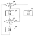
図4は、シール機構の加圧配管回路系統図で、図5は、図4の加圧配管回路によってシール部を制御する制御フローチャート図である。 4 is a pressurization piping circuit diagram of the seal mechanism, and FIG. 5 is a control flowchart for controlling the seal portion by the pressurization piping circuit of FIG.
図4に示すように、シール機構5の加圧配管回路30は、管路構造1内に圧力気体を送り出すと共にシール機構5の加圧源としての送風機31と、送風機31の風量および風圧を調整するための電気式または流体圧式の自動開閉弁32と、電気式または流体圧式の自動開閉弁33、34、35と、送風機31の吹出口と管路部材4内の圧力を測定する圧力センサー36、37と、その圧力差を検知する差圧検知器38と、加圧圧力源としての送風機31の補助加圧源としての加圧ボンベまたは加圧発生装置39と、開閉用バルブ40と、補助加圧源の圧力調整装置41とを有している。
As shown in FIG. 4, the
また、加圧配管回路30は、圧力センサー36、37、差圧検知器38、自動開閉弁33、34、35を総合的に制御する制御盤45、自動開閉ダンパー32、圧力センサー36、37、差圧検知器38を接続する配線47を有している。
The pressurizing
このような加圧配管回路30における動作は、構造物の移動に追従して、管路部材2、2A、4、4Aが伸縮して所定の位置で停止した後、図5の制御フローに示されるように動作される。
Such an operation in the
図示されるように、先ず、ステップS1において運転スイッチが「入」に入れられることによって送風機31の運転を開始する。
As shown in the drawing, first, the operation of the
次いで、ステップS2において、自動開閉弁34が開かれて開状態とされ、自動開閉弁33、35が閉じられて閉状態とされる。
Next, in step S2, the automatic open /
そして、ステップS1での送風機31が運転された後に、ステップS3において、送風機31の出口直後の圧力数値を圧力センサー36で測定すると共に、管路部材2または4内の圧力数値を圧力センサー37で測定して、その圧力差を差圧検知器38で検知する。
After the
この時に、圧力差が所定の数値以上、例えば約200mmAq以上であれば、ステップS3の「NO」に従って進んで、シール部5の弾性部材8が十分に外方に拡張されて管路部材2Aの内壁面に密着してシール効果が発揮される。こうして、送風機31からの圧力気体のような流体が管路部材2、2A、4、4Aから漏洩することなく目標箇所に到達することができ、シールする所期の目的を達成することができる。
At this time, if the pressure difference is equal to or greater than a predetermined numerical value, for example, approximately 200 mmAq, the process proceeds according to “NO” in step S3, and the elastic member 8 of the
また、ステップS3において、もし、差圧検知器38で検知された圧力差圧が所定の数値以下、例えば200mmAq以下、の時には、ステップS3の「YES」に従ってステップS4へと進んで、ステップS4で、自動開閉弁34、35を閉じて閉状態とし、自動開閉弁33を開いて開状態にすることによって、補助加圧源としての加圧ボンベのような加圧発生装置39によって圧力気体の供給を補助し、これによってシール機構5の弾性部材8が十分に拡張して管路部材2、2Aの内壁面に密着してシール効果が発揮されるようにバックアップする。
In step S3, if the pressure differential pressure detected by the
以上の動作によって、送風機31からの気体のような流体が管路部材2、2A、4、4Aを漏洩することなしに目標箇所に到達させることができる。また、補助圧力源の加圧発生装置39の圧力調整装置41によりシール機構5の弾性部材8にかかる拡張加圧圧力を所要圧力に調整することによって、シール機構5の弾性部材8を何ら損傷することがないように加圧圧力の大きさを必要な十分な数値に調整することができる。
With the above operation, a fluid such as gas from the
また、管路部材2、2A、4、4Aを取付けている構造物100を伸縮、移動させる時は、運転スイッチを切って「切」にして、送風機31の運転を停止し、自動開閉弁33、34を閉じて閉状態とし、自動開閉弁35を開いて開状態とするステップS5とする。これによって、シール機構5の弾性部材8内の圧力が減圧されて弾性部材8が管路部材2Aの内壁面から離れるので、構造物100の移動が可能となる。
Further, when the
このように自動開閉弁33、34を閉じて自動開閉弁35を開くことによって、シール部5への加圧圧力を減じ、シール機構5の弾性部材8を拡張状態から縮小状態にすることで、管路部材2、2A、4、4Aを構造物100の移動に追従して伸縮させて構造物100を伸縮、移動することができる。従って、この場合に、シール機構5の弾性部材8の破損を好適に防止することができる。
By closing the automatic open /
更に、管路部材2、2A、4、4Aを取付けている構造物100が所定の位置で停止して、再度送風機31により目的箇所に送風する時には、上述した制御フロー図の動作を繰返すことによってシール機構5の拡張、縮小機能を発揮することができる。なお、管路部材2、2A、4、4Aとシール機構5は単数に限らず、目的によって複数の管路部材2、2A、4、4Aを設置することができる。
Furthermore, when the
図6および図7は、シール部5の弾性部材8、またはキャスター6の点検、整備時に、管路部材2、2A、4、4Aを点検、整備、交換できる位置に停止して、管路構造1の管路部材2、2A、4、4Aを取外し可能な範囲内に停止させる状態を示している。
6 and 7 show that the
図6、図7はシール機構5やキャスター6を点検、整備、交換する状態を示しており、シール機構5やキャスター6を点検、整備、交換する時には、図6に示される位置で、先ず、管路部材2、2Aのフランジ部2a、12におけるボルト20を取外し、管路部材2Aを管路部材4に沿って図6で左方に動かして、図7の位置にまで移動する。
6 and 7 show a state in which the
次いで、管路部材4、4Aにおける管部材7を先ずシール機構5の環状部材14から取外し、そして、管路部材4、4Aのフランジ部16、18におけるボルト21を取外して管路部材4Aを管路部材4から取外して、管路部材2、2A、4、4Aの夫々の状態が確認できる位置または状態にまで移動、配置して管路構造1の各部の点検、整備を実施する。もし、管路部材4Aを交換する時には、ボルト21を取外して、予備として準備している別の新たな管路部材4Aと交換することができる。
Next, the
管路部材2、2Aのボルト20を取外す前に、管路部材2、2Aが落下しないように構造物100に対して仮設の支持材102やチェーン等により仮止めして支持することが好適であり、必要となる。なお、本体である管路部材2、2Aと取外し可能な管路部材4、4Aの接続部分は気体の漏洩がないようにパッキン13、17によってしっかりとフランジ部2a、12、16、18におけるシール性が確保される。
Before removing the
構造物100に適宜な支持材101、102によって取付けられた剛性の伸縮可能な管路構造1は、好適には撓みが極力少なく、軽く、且つ強度が必要にして十分にあり、更に、結露発生が少ない材質で製作されるのが好適である。また、外部設置による紫外線および外気温、湿度等に露呈されるような環境に設置される場合を考慮して耐候性のある材質の選択や、相当の効果をもたらす塗料を塗布する等の措置をすることが好ましい。
The rigid
本発明は、飛行場に駐機している航空機の機内を冷房および暖房する時に、航空機毎に大きさの異なる乗客乗降用の搭乗橋が旅客ターミナルビルと各種航空機の間を伸縮する時に、搭乗橋の天井上部、横壁部または床下部に、伸縮可能な風路として有用な管路構造を製造、販売する産業分野で利用することができる。 The present invention relates to a boarding bridge when a passenger boarding board having different sizes for each aircraft expands and contracts between a passenger terminal building and various types of aircraft when cooling and heating an aircraft parked at an airfield. Can be used in an industrial field in which a pipe structure useful as an extendable air passage is manufactured and sold in the upper part of the ceiling, the side wall part, or the lower part of the floor.
1 管路構造
2、2A 管路部材
3 閉鎖板部材
4、4A 管路部材
5 シール機構
6 キャスター
7 管部材
8 弾性部材
10 接続構造
12 フランジ部
13 パッキン
14 環状部材
15 溝部
16 フランジ部
17 パッキン
18 フランジ部
20 ボルト
21 ボルト
22 転動部材
24 支承部材
25 取付部材
26 ボルト
30 加圧配管回路
31 送風機
32 自動開閉ダンパー
33 自動開閉弁
34 自動開閉弁
35 自動開閉弁
36 圧力センサー
37 圧力センサー
38 差圧検知器
39 加圧発生装置
40 開閉用バルブ
41 圧力調整装置
45 制御盤
47 配線
100 構造物
101 支持材
102 支持材
DESCRIPTION OF
Claims (8)
送風機を作動して管路部材に送風する工程と、
送風機出口の圧力と管路部材内の圧力とを圧力センサーで測定して圧力差を差圧検知器で検知する工程と、
上記圧力差が所定の数値以上の時に、圧力空気の一部をシール機構に供給して拡張して両管路部材の間をシールする工程と、
から成ることを特徴とする管路構造を伸縮する方法。 A seal mechanism provided on the outer periphery of an end of one of the at least two pipe members of different sizes that can be expanded and contracted with each other, and the one pipe member can be moved. In a method of expanding and contracting a pipe line structure including a wheel member provided to support a pressure fan circuit, a pressure pipe circuit having a plurality of automatic opening / closing valves and a control panel,
A step of operating the blower to blow air to the pipe member;
Measuring the pressure at the outlet of the blower and the pressure in the pipe member with a pressure sensor and detecting the pressure difference with a differential pressure detector; and
When the pressure difference is equal to or greater than a predetermined value, supplying a part of the pressure air to the seal mechanism and expanding it to seal between the two pipe members;
A method for expanding and contracting a pipeline structure characterized by comprising:
更に有することを特徴とする請求項6記載の管路構造を伸縮する方法。 When the pressure difference is equal to or less than a predetermined value, a process of assisting the seal by expanding the seal mechanism by assisting the supply of pressurized air by the pressurizing generator as an auxiliary pressure source,
The method for expanding and contracting the conduit structure according to claim 6, further comprising:
Priority Applications (1)
| Application Number | Priority Date | Filing Date | Title |
|---|---|---|---|
| JP2007033127A JP2008196617A (en) | 2007-02-14 | 2007-02-14 | Pipe structure and method for expanding and contracting the pipe structure |
Applications Claiming Priority (1)
| Application Number | Priority Date | Filing Date | Title |
|---|---|---|---|
| JP2007033127A JP2008196617A (en) | 2007-02-14 | 2007-02-14 | Pipe structure and method for expanding and contracting the pipe structure |
Publications (1)
| Publication Number | Publication Date |
|---|---|
| JP2008196617A true JP2008196617A (en) | 2008-08-28 |
Family
ID=39755750
Family Applications (1)
| Application Number | Title | Priority Date | Filing Date |
|---|---|---|---|
| JP2007033127A Pending JP2008196617A (en) | 2007-02-14 | 2007-02-14 | Pipe structure and method for expanding and contracting the pipe structure |
Country Status (1)
| Country | Link |
|---|---|
| JP (1) | JP2008196617A (en) |
Citations (6)
| Publication number | Priority date | Publication date | Assignee | Title |
|---|---|---|---|---|
| JPS4812959Y1 (en) * | 1969-01-20 | 1973-04-09 | ||
| JPS4965755U (en) * | 1972-09-27 | 1974-06-08 | ||
| JPH03211301A (en) * | 1990-01-17 | 1991-09-17 | Babcock Hitachi Kk | Device for safe operation of boiler |
| JPH07105963A (en) * | 1993-10-08 | 1995-04-21 | Ishikawajima Harima Heavy Ind Co Ltd | Air supply device for fuel cell |
| JPH105785A (en) * | 1996-06-20 | 1998-01-13 | Ebara Corp | Deep water stratum aerator |
| JP2004052349A (en) * | 2002-07-19 | 2004-02-19 | Fudo Constr Co Ltd | Telescopic hollow tube |
-
2007
- 2007-02-14 JP JP2007033127A patent/JP2008196617A/en active Pending
Patent Citations (6)
| Publication number | Priority date | Publication date | Assignee | Title |
|---|---|---|---|---|
| JPS4812959Y1 (en) * | 1969-01-20 | 1973-04-09 | ||
| JPS4965755U (en) * | 1972-09-27 | 1974-06-08 | ||
| JPH03211301A (en) * | 1990-01-17 | 1991-09-17 | Babcock Hitachi Kk | Device for safe operation of boiler |
| JPH07105963A (en) * | 1993-10-08 | 1995-04-21 | Ishikawajima Harima Heavy Ind Co Ltd | Air supply device for fuel cell |
| JPH105785A (en) * | 1996-06-20 | 1998-01-13 | Ebara Corp | Deep water stratum aerator |
| JP2004052349A (en) * | 2002-07-19 | 2004-02-19 | Fudo Constr Co Ltd | Telescopic hollow tube |
Similar Documents
| Publication | Publication Date | Title |
|---|---|---|
| KR101840682B1 (en) | Linked complex ventilation system of pipes | |
| US20150023735A1 (en) | System for renovating a sewer manhole | |
| CN105058055A (en) | Manufacturing and installation method for built-in flange and air hose for building construction | |
| CN107654789A (en) | A kind of analogy method of long oil/gas pipe line dimension repairing process | |
| CN102519110A (en) | Subway platform ventilation and smoke removal distribution structure in station with opened-closed system | |
| JP2008196617A (en) | Pipe structure and method for expanding and contracting the pipe structure | |
| KR20120108316A (en) | Locally controled ventilation duct system provided with fire detector and opening/closing apparatus | |
| JP6404576B2 (en) | Curing method for tunnel lining concrete | |
| CN107434102A (en) | A kind of pipeline arranging frame | |
| JP2006125806A (en) | Air-conditioning equipment, method for installing outdoor air conditioner, and method for producing air-conditioning equipment | |
| CN105840099A (en) | Polar region drilling machine | |
| KR20200016418A (en) | folding type fire demand water discharge device for fire hydrant | |
| US9903521B2 (en) | Upstream pipe plug | |
| JP7337459B2 (en) | How to repair air conditioning equipment | |
| KR20200009901A (en) | Method of preventing water damage of wet sprinklers | |
| WO2014182482A1 (en) | Apparatus for spraying reinforcing material onto an interior surface of a pipe | |
| JP7650826B2 (en) | Method for manufacturing a fire extinguishing system | |
| CN205445466U (en) | Polar region rig | |
| Marchiori et al. | NEOSTEL: the first innovative observatory for the FlyEye Telescopes | |
| CN107435761A (en) | Pipeline arranging frame for building | |
| Connection | Issue D | |
| CN213479389U (en) | Conveniently maintain assembled for building pipe fitting of changing | |
| CN213847378U (en) | Auxiliary heat dissipation system of high-voltage frequency converter | |
| JP5536515B2 (en) | Maintenance method of flange pipe | |
| CN102383579A (en) | Exhaust pipe structure |
Legal Events
| Date | Code | Title | Description |
|---|---|---|---|
| A621 | Written request for application examination |
Effective date: 20100215 Free format text: JAPANESE INTERMEDIATE CODE: A621 |
|
| A521 | Written amendment |
Effective date: 20100303 Free format text: JAPANESE INTERMEDIATE CODE: A523 |
|
| RD02 | Notification of acceptance of power of attorney |
Effective date: 20100325 Free format text: JAPANESE INTERMEDIATE CODE: A7422 |
|
| A521 | Written amendment |
Free format text: JAPANESE INTERMEDIATE CODE: A821 Effective date: 20100326 |
|
| A977 | Report on retrieval |
Effective date: 20120131 Free format text: JAPANESE INTERMEDIATE CODE: A971007 |
|
| A131 | Notification of reasons for refusal |
Effective date: 20120321 Free format text: JAPANESE INTERMEDIATE CODE: A131 |
|
| A02 | Decision of refusal |
Effective date: 20120814 Free format text: JAPANESE INTERMEDIATE CODE: A02 |