JP2009132829A - Biomass decomposed gas treatment device - Google Patents
Biomass decomposed gas treatment device Download PDFInfo
- Publication number
- JP2009132829A JP2009132829A JP2007311194A JP2007311194A JP2009132829A JP 2009132829 A JP2009132829 A JP 2009132829A JP 2007311194 A JP2007311194 A JP 2007311194A JP 2007311194 A JP2007311194 A JP 2007311194A JP 2009132829 A JP2009132829 A JP 2009132829A
- Authority
- JP
- Japan
- Prior art keywords
- biomass
- decomposition gas
- liquid fuel
- biomass decomposition
- fuel
- Prior art date
- Legal status (The legal status is an assumption and is not a legal conclusion. Google has not performed a legal analysis and makes no representation as to the accuracy of the status listed.)
- Pending
Links
- 239000002028 Biomass Substances 0.000 title claims abstract description 254
- 239000000446 fuel Substances 0.000 claims abstract description 239
- 239000007788 liquid Substances 0.000 claims abstract description 196
- 239000002828 fuel tank Substances 0.000 claims abstract description 79
- 230000009977 dual effect Effects 0.000 claims abstract description 51
- 238000002309 gasification Methods 0.000 claims abstract description 34
- 238000005201 scrubbing Methods 0.000 claims abstract description 33
- XLYOFNOQVPJJNP-UHFFFAOYSA-N water Substances O XLYOFNOQVPJJNP-UHFFFAOYSA-N 0.000 claims abstract description 29
- 238000002347 injection Methods 0.000 claims abstract description 25
- 239000007924 injection Substances 0.000 claims abstract description 25
- 238000000354 decomposition reaction Methods 0.000 claims description 183
- 239000000428 dust Substances 0.000 claims description 40
- 238000001514 detection method Methods 0.000 claims description 30
- 238000004140 cleaning Methods 0.000 claims description 17
- 238000005336 cracking Methods 0.000 claims description 11
- 239000007789 gas Substances 0.000 abstract description 213
- 230000002000 scavenging effect Effects 0.000 abstract 2
- 239000002737 fuel gas Substances 0.000 abstract 1
- 239000000243 solution Substances 0.000 abstract 1
- 238000002485 combustion reaction Methods 0.000 description 14
- UFHFLCQGNIYNRP-UHFFFAOYSA-N Hydrogen Chemical compound [H][H] UFHFLCQGNIYNRP-UHFFFAOYSA-N 0.000 description 5
- 239000001257 hydrogen Substances 0.000 description 5
- 229910052739 hydrogen Inorganic materials 0.000 description 5
- 239000002994 raw material Substances 0.000 description 5
- VYPSYNLAJGMNEJ-UHFFFAOYSA-N Silicium dioxide Chemical compound O=[Si]=O VYPSYNLAJGMNEJ-UHFFFAOYSA-N 0.000 description 4
- VNWKTOKETHGBQD-UHFFFAOYSA-N methane Chemical compound C VNWKTOKETHGBQD-UHFFFAOYSA-N 0.000 description 4
- UGFAIRIUMAVXCW-UHFFFAOYSA-N Carbon monoxide Chemical compound [O+]#[C-] UGFAIRIUMAVXCW-UHFFFAOYSA-N 0.000 description 3
- 229910002091 carbon monoxide Inorganic materials 0.000 description 3
- 239000000203 mixture Substances 0.000 description 3
- 239000002699 waste material Substances 0.000 description 3
- IJGRMHOSHXDMSA-UHFFFAOYSA-N Atomic nitrogen Chemical compound N#N IJGRMHOSHXDMSA-UHFFFAOYSA-N 0.000 description 2
- QVGXLLKOCUKJST-UHFFFAOYSA-N atomic oxygen Chemical compound [O] QVGXLLKOCUKJST-UHFFFAOYSA-N 0.000 description 2
- 238000010586 diagram Methods 0.000 description 2
- 230000000694 effects Effects 0.000 description 2
- 238000005516 engineering process Methods 0.000 description 2
- 239000012535 impurity Substances 0.000 description 2
- 229910052760 oxygen Inorganic materials 0.000 description 2
- 239000001301 oxygen Substances 0.000 description 2
- 238000003672 processing method Methods 0.000 description 2
- 239000004576 sand Substances 0.000 description 2
- 238000005507 spraying Methods 0.000 description 2
- 238000011144 upstream manufacturing Methods 0.000 description 2
- 241000195493 Cryptophyta Species 0.000 description 1
- NINIDFKCEFEMDL-UHFFFAOYSA-N Sulfur Chemical compound [S] NINIDFKCEFEMDL-UHFFFAOYSA-N 0.000 description 1
- 239000002154 agricultural waste Substances 0.000 description 1
- 150000004945 aromatic hydrocarbons Chemical class 0.000 description 1
- 239000010796 biological waste Substances 0.000 description 1
- 239000003795 chemical substances by application Substances 0.000 description 1
- 239000003245 coal Substances 0.000 description 1
- 150000001875 compounds Chemical class 0.000 description 1
- 238000007796 conventional method Methods 0.000 description 1
- 238000007599 discharging Methods 0.000 description 1
- 238000007667 floating Methods 0.000 description 1
- 239000012530 fluid Substances 0.000 description 1
- 230000005484 gravity Effects 0.000 description 1
- 238000010438 heat treatment Methods 0.000 description 1
- 239000011344 liquid material Substances 0.000 description 1
- 238000004519 manufacturing process Methods 0.000 description 1
- 238000000034 method Methods 0.000 description 1
- 229910052757 nitrogen Inorganic materials 0.000 description 1
- 230000003287 optical effect Effects 0.000 description 1
- 239000005416 organic matter Substances 0.000 description 1
- 230000003647 oxidation Effects 0.000 description 1
- 238000007254 oxidation reaction Methods 0.000 description 1
- 238000011084 recovery Methods 0.000 description 1
- 239000000377 silicon dioxide Substances 0.000 description 1
- 229910052717 sulfur Inorganic materials 0.000 description 1
- 239000011593 sulfur Substances 0.000 description 1
- 239000011269 tar Substances 0.000 description 1
- 238000005979 thermal decomposition reaction Methods 0.000 description 1
- 238000005406 washing Methods 0.000 description 1
- 239000002023 wood Substances 0.000 description 1
- 239000002916 wood waste Substances 0.000 description 1
Images

Classifications
-
- F—MECHANICAL ENGINEERING; LIGHTING; HEATING; WEAPONS; BLASTING
- F02—COMBUSTION ENGINES; HOT-GAS OR COMBUSTION-PRODUCT ENGINE PLANTS
- F02D—CONTROLLING COMBUSTION ENGINES
- F02D19/00—Controlling engines characterised by their use of non-liquid fuels, pluralities of fuels, or non-fuel substances added to the combustible mixtures
- F02D19/06—Controlling engines characterised by their use of non-liquid fuels, pluralities of fuels, or non-fuel substances added to the combustible mixtures peculiar to engines working with pluralities of fuels, e.g. alternatively with light and heavy fuel oil, other than engines indifferent to the fuel consumed
- F02D19/0663—Details on the fuel supply system, e.g. tanks, valves, pipes, pumps, rails, injectors or mixers
- F02D19/0668—Treating or cleaning means; Fuel filters
- F02D19/0671—Means to generate or modify a fuel, e.g. reformers, electrolytic cells or membranes
-
- Y—GENERAL TAGGING OF NEW TECHNOLOGICAL DEVELOPMENTS; GENERAL TAGGING OF CROSS-SECTIONAL TECHNOLOGIES SPANNING OVER SEVERAL SECTIONS OF THE IPC; TECHNICAL SUBJECTS COVERED BY FORMER USPC CROSS-REFERENCE ART COLLECTIONS [XRACs] AND DIGESTS
- Y02—TECHNOLOGIES OR APPLICATIONS FOR MITIGATION OR ADAPTATION AGAINST CLIMATE CHANGE
- Y02T—CLIMATE CHANGE MITIGATION TECHNOLOGIES RELATED TO TRANSPORTATION
- Y02T10/00—Road transport of goods or passengers
- Y02T10/10—Internal combustion engine [ICE] based vehicles
- Y02T10/30—Use of alternative fuels, e.g. biofuels
Landscapes
- Engineering & Computer Science (AREA)
- Chemical & Material Sciences (AREA)
- Oil, Petroleum & Natural Gas (AREA)
- Combustion & Propulsion (AREA)
- Mechanical Engineering (AREA)
- General Engineering & Computer Science (AREA)
- Output Control And Ontrol Of Special Type Engine (AREA)
- Industrial Gases (AREA)
Abstract
Description
本発明は、バイオマス分解ガス処理装置の技術に関し、より詳しくはバイオマスを熱分解して得られるバイオマス分解ガスと、液体燃料とを燃料としてデュアルフューエルエンジンを駆動させるバイオマス分解ガス処理装置の技術に関する。 The present invention relates to a technology of a biomass decomposition gas processing apparatus, and more particularly to a technology of a biomass decomposition gas processing apparatus that drives a dual fuel engine using a biomass decomposition gas obtained by thermally decomposing biomass and a liquid fuel as fuel.
従来、バイオマス分解ガスの原料としてバイオマス等の廃棄物を熱分解すると、バイオマス分解ガス、ダスト、およびタールなどが発生することが知られている。これらは、バイオマス等の廃棄物の組成や、ガス化の条件によって、それぞれの生成量や成分が異なる。 Conventionally, it is known that when a waste such as biomass is pyrolyzed as a raw material for biomass decomposition gas, biomass decomposition gas, dust, tar, and the like are generated. The amount and components of these components vary depending on the composition of waste such as biomass and gasification conditions.
例えば、バイオマス等を部分燃焼あるいは部分酸化することで熱分解し、水素やメタン等のバイオマス分解ガスを発生させるガス化炉は公知となっている。前記ガス化炉から得られたバイオマス分解ガスは、前記水素やメタンの他、ダストやタール等が含まれている。このようなバイオマス分解ガスを工業製品や燃料として利用する際には、前記タール及びダストを除去することが必要である。そこで、従来、図7に示すようにバイオマス分解ガスを発生させるガス化炉201と、ダストを付着させて除去するフィルタ202と、前記バイオマス分解ガスから前記タールを除去する装置であって、前記タールを洗浄油によりスクラビングする油スクラビング及び/または水によりスクラビングする水スクラビングを行うスクラバ203と、を具備するバイオマス分解ガス処理装置200が公知となっている(例えば特許文献1参照)。
For example, gasification furnaces that thermally decompose biomass by partial combustion or partial oxidation to generate biomass decomposition gas such as hydrogen and methane are known. The biomass decomposition gas obtained from the gasifier contains dust, tar, and the like in addition to the hydrogen and methane. When such a biomass decomposition gas is used as an industrial product or fuel, it is necessary to remove the tar and dust. Therefore, conventionally, as shown in FIG. 7, a
一方、前記バイオマス分解ガス及び軽油等の液体燃料を混合した混合燃料により機関を駆動させるデュアルフューエルエンジン204は公知となっている(例えば特許文献2参照)。
On the other hand, a
従来のバイオマス分解ガスの洗浄方法においては、バイオマス分解ガスからタールを除去するために油スクラビング及び/または水スクラビングを行っている。スクラビングは、噴霧などにより洗浄油または水をバイオマス分解ガスに接触させることにより温度を下げ、不純物を除去することであり、油スクラビング及び/または水スクラビングを行うために、スクラバ203を設けなければならず設備コストが多くかかる。また、洗浄に使用した洗浄油または水は、タール及びダストを含有しているため、数回繰り返して使用した後は図7に示すように廃棄処理しなければならず、廃棄処理コストが多くかかっていた。
また、前記タールは軽油等の液体燃料に含有されればデュアルフューエルエンジン204において燃焼させることが可能であるが、前記バイオマス分解ガスに含有されればデュアルフューエルエンジン204において燃焼させることはできない。また、前記タールはバイオマス分解ガスに含有されれば、前記デュアルフューエルエンジン204へバイオマス分解ガスを供給するための導入管235内においてタールが結晶化してしまい、導入管235の詰まりの原因となることがあった。
In the conventional method for cleaning biomass cracking gas, oil scrubbing and / or water scrubbing is performed to remove tar from the biomass cracking gas. Scrubbing is the removal of impurities by bringing cleaning oil or water into contact with the biomass decomposition gas by spraying or the like, and a
Further, if the tar is contained in a liquid fuel such as light oil, it can be burned in the
そこで、本発明はかかる課題に鑑み、油スクラビングと水スクラビングを行うことなく、タールをデュアルフューエルエンジンの燃料である液体燃料中に捕集してバイオマス分解ガスからタールを除去することができるバイオマス分解ガス処理装置を提供する。 Therefore, in view of such problems, the present invention captures tar in liquid fuel that is fuel of a dual fuel engine and removes tar from biomass decomposition gas without performing oil scrubbing and water scrubbing. A gas processing apparatus is provided.
本発明の解決しようとする課題は以上の如くであり、次にこの課題を解決するための手段を説明する。 The problems to be solved by the present invention are as described above. Next, means for solving the problems will be described.
即ち、請求項1においては、バイオマスを熱分解して得られるバイオマス分解ガスと、液体燃料とを燃料としてデュアルフューエルエンジンを駆動させるバイオマス分解ガス処理装置において、バイオマスを熱分解してバイオマス分解ガスを発生させるガス化炉と、該ガス化炉からバイオマス分解ガスを導入してバイオマス分解ガスに含有されるダストを除去するフィルタと、該フィルタからバイオマス分解ガスを液体燃料中に導入して含有されるタールを捕集して、当該バイオマス分解ガスを前記デュアルフューエルエンジンの給気管に送るとともに、液体燃料を前記デュアルフューエルエンジンの燃料噴射ポンプに供給する液体燃料タンクとを備えるものである。 That is, in claim 1, in a biomass decomposition gas processing apparatus that drives a dual fuel engine using a biomass decomposition gas obtained by pyrolyzing biomass and a liquid fuel as fuel, the biomass decomposition gas is decomposed by thermally decomposing the biomass. A gasification furnace to be generated, a filter for introducing biomass decomposition gas from the gasification furnace to remove dust contained in the biomass decomposition gas, and a biomass decomposition gas introduced from the filter into liquid fuel A tarball is collected, the biomass decomposition gas is sent to the supply pipe of the dual fuel engine, and a liquid fuel tank is provided to supply liquid fuel to the fuel injection pump of the dual fuel engine.
請求項2においては、前記フィルタからのバイオマス分解ガスを導入する液体燃料タンク内部に板状部材を配置したものである。 In Claim 2, a plate-shaped member is arrange | positioned inside the liquid fuel tank which introduce | transduces biomass decomposition gas from the said filter.
請求項3においては、前記液体燃料タンクの底部に設けられたドレン通路に設けた電磁開閉式の排出弁と、前記液体燃料タンクの燃料噴射ポンプへの燃料供給口より低い位置に配置した、液体燃料タンク内の水及び不溶タールのレベルを検出するための検出センサと、前記検出センサの検出値を入力して、前記検出値が設定値以上であると判断した場合には前記排出弁を開くように制御する制御装置とを備えるものである。 According to a third aspect of the present invention, there is provided a liquid disposed at a position lower than an electromagnetic open / close discharge valve provided in a drain passage provided at a bottom of the liquid fuel tank and a fuel supply port to a fuel injection pump of the liquid fuel tank. A detection sensor for detecting the level of water and insoluble tar in the fuel tank and a detection value of the detection sensor are input, and when it is determined that the detection value is equal to or higher than a set value, the discharge valve is opened. And a control device for controlling as described above.
請求項4においては、前記燃料タンク内へフィルタからのバイオマス分解ガスを導入する配管の出口に配管用フィルタを設けたものである。 According to a fourth aspect of the present invention, a pipe filter is provided at the outlet of a pipe for introducing the biomass decomposition gas from the filter into the fuel tank.
請求項5においては、バイオマスを熱分解して得られるバイオマス分解ガスと、液体燃料とを燃料としてデュアルフューエルエンジンを駆動させるバイオマス分解ガス処理装置において、バイオマスを熱分解してバイオマス分解ガスを発生させるガス化炉と、該ガス化炉からバイオマス分解ガスを導入して該バイオマス分解ガスに含有されるダストを除去するフィルタと、ダストを除去した後のバイオマス分解ガスを洗浄油によりスクラビングするスクラバと、該スクラバからバイオマス分解ガスを液体燃料中に導入して含有されるタールを捕集して、当該バイオマス分解ガスを前記デュアルフューエルエンジンの給気管に送るとともに、液体燃料を前記デュアルフューエルエンジンの燃料噴射ポンプに供給する液体燃料タンクとを備えるものである。 In Claim 5, in the biomass decomposition gas processing apparatus which drives a dual fuel engine by using biomass decomposition gas obtained by thermally decomposing biomass and liquid fuel as fuel, biomass is thermally decomposed to generate biomass decomposition gas A gasification furnace, a filter that removes dust contained in the biomass decomposition gas by introducing biomass decomposition gas from the gasification furnace, a scrubber that scrubs the biomass decomposition gas after removing the dust with cleaning oil, The tar is contained by introducing the biomass decomposition gas into the liquid fuel from the scrubber, and the biomass decomposition gas is sent to the supply pipe of the dual fuel engine, and the liquid fuel is injected into the fuel of the dual fuel engine. A liquid fuel tank for supplying to the pump It is.
請求項6においては、バイオマスを熱分解して得られるバイオマス分解ガスを燃料としてガスエンジンを駆動させ、液体燃料を燃料として液体燃料エンジンを駆動させるバイオマス分解ガス処理装置において、バイオマスを熱分解してバイオマス分解ガスを発生させるガス化炉と、該ガス化炉からバイオマス分解ガスを導入してバイオマス分解ガスに含有されるダストを除去するフィルタと、該フィルタからバイオマス分解ガスを液体燃料中に導入して含有されるタールを捕集して、当該バイオマス分解ガスを前記ガスエンジンの給気管に送るとともに、液体燃料を前記液体燃料エンジンの燃料噴射ポンプに供給する液体燃料タンクとを備えるものである。 In claim 6, in a biomass decomposition gas processing apparatus that drives a gas engine using biomass decomposition gas obtained by pyrolyzing biomass as fuel and driving a liquid fuel engine using liquid fuel as fuel, the biomass is pyrolyzed. A gasification furnace for generating a biomass decomposition gas; a filter for introducing the biomass decomposition gas from the gasification furnace to remove dust contained in the biomass decomposition gas; and introducing the biomass decomposition gas into the liquid fuel from the filter And a liquid fuel tank that feeds the biomass decomposition gas to the supply pipe of the gas engine and supplies liquid fuel to a fuel injection pump of the liquid fuel engine.
本発明の効果として、以下に示すような効果を奏する。 As effects of the present invention, the following effects can be obtained.
請求項1においては、タールを除去するために使用する油である液体燃料を廃棄処理する必要がなくなるため処理コストが削減されることとなる。また、油スクラビング及び/又は水スクラビングを行うことなく、バイオマス分解ガスからタールを捕集することができるため、スクラビングを行うために従来設けていたスクラバを設ける必要がなくなり、コストが削減されることとなる。また、液体燃料にタールを含有させることにより、デュアルフューエルエンジンの燃料として使用することができ、エネルギー効率が上昇する。 According to the first aspect of the present invention, it is not necessary to dispose of the liquid fuel that is oil used for removing tar, so that the processing cost is reduced. In addition, tar can be collected from the biomass decomposition gas without performing oil scrubbing and / or water scrubbing, so there is no need to provide a scrubber that has been conventionally provided for scrubbing, and costs can be reduced. It becomes. Further, by including tar in the liquid fuel, it can be used as a fuel for a dual fuel engine, and energy efficiency is increased.
請求項2においては、液体燃料タンクにおいて、バイオマス分解ガスと液体燃料とが接触する機会が増加するため、液体燃料タンク内で捕集されるタールの量が増加することとなる。 According to the second aspect of the present invention, since the chance of contact between the biomass decomposition gas and the liquid fuel increases in the liquid fuel tank, the amount of tar collected in the liquid fuel tank increases.
請求項3においては、液体燃料タンク内に流入した水及び不溶タールがデュアルフューエルエンジン内に流入しないようにすることができる。 According to the third aspect of the present invention, water and insoluble tar that have flowed into the liquid fuel tank can be prevented from flowing into the dual fuel engine.
請求項4においては、配管より液体燃料タンクへ導入されるバイオマス分解ガスの気泡が配管用フィルタを通過することで、体積の小さな複数の気泡となることにより、表面積が増加して、バイオマス分解ガスと液体燃料とが接触する機会が増加するため、液体燃料タンク内で捕集されるタールの量が増加することとなる。 In claim 4, the biomass decomposition gas introduced from the pipe into the liquid fuel tank passes through the pipe filter and becomes a plurality of bubbles having a small volume. Since the chance of contact with the liquid fuel increases, the amount of tar collected in the liquid fuel tank increases.
請求項5においては、バイオマス分解ガスに含有されるタールをほとんど除去して、液体燃料中に捕集することが可能となる。また、従来は廃棄処理していたタールを燃料として使用することにより、エネルギー効率が上昇する。 In claim 5, it is possible to remove most of the tar contained in the biomass decomposition gas and collect it in the liquid fuel. In addition, energy efficiency is increased by using tar that has been conventionally disposed of as fuel.
請求項6においては、タールを除去するために使用する油である液体燃料を廃棄処理する必要がなくなるため処理コストが削減されることとなる。また、油スクラビング及び/又は水スクラビングを行うことなく、バイオマス分解ガスからタールを捕集することができるため、スクラビングを行うために従来設けていたスクラバを設ける必要がなくなり、コストが削減されることとなる。また、バイオマス分解ガスからタールを除去することにより、ガスエンジンの燃料として使用することができ、液体燃料にタールを含有させることにより、液体燃料エンジンの燃料として使用することができ、エネルギー効率が上昇する。 According to the sixth aspect of the present invention, it is not necessary to dispose of the liquid fuel that is oil used for removing tar, so that the processing cost is reduced. In addition, tar can be collected from the biomass decomposition gas without performing oil scrubbing and / or water scrubbing, so there is no need to provide a scrubber that has been conventionally provided for scrubbing, and costs can be reduced. It becomes. Moreover, by removing tar from biomass cracked gas, it can be used as fuel for gas engines, and by adding tar to liquid fuel, it can be used as fuel for liquid fuel engines, increasing energy efficiency To do.
次に、発明の実施の形態を説明する。
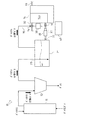
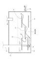
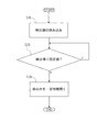
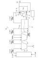
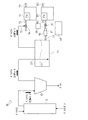
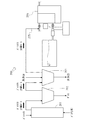
図1は本発明の一実施例に係るバイオマス分解ガス処理装置の全体的な構成を示したフロー図、図2は液体燃料タンク及び邪魔板の一例を示す概略図、図3は液体燃料タンク及び検出センサの一例を示す概略図、図4は排出弁の制御を示すフローチャート図、図5はスクラバ及び液体燃料タンクによって構成される洗浄装置を具備するバイオマス分解ガス処理装置のフロー図、図6はガスエンジン及び液体燃料エンジンを具備するバイオマス分解ガス処理装置のフロー図、図7は従来のバイオマス分解ガス処理装置のフロー図である。
Next, embodiments of the invention will be described.
FIG. 1 is a flowchart showing an overall configuration of a biomass decomposition gas processing apparatus according to an embodiment of the present invention, FIG. 2 is a schematic diagram showing an example of a liquid fuel tank and baffle plates, and FIG. 4 is a schematic diagram showing an example of a detection sensor, FIG. 4 is a flowchart showing control of a discharge valve, FIG. 5 is a flow chart of a biomass decomposition gas processing apparatus including a cleaning device constituted by a scrubber and a liquid fuel tank, and FIG. FIG. 7 is a flowchart of a conventional biomass decomposition gas processing apparatus, and FIG. 7 is a flowchart of a biomass decomposition gas processing apparatus including a gas engine and a liquid fuel engine.
まず、本発明にかかるバイオマス分解ガス処理装置10について図1を用いて説明する。
バイオマス分解ガス処理装置10は、バイオマスを熱分解してバイオマス分解ガスを発生させるガス化炉11と、該ガス化炉11からバイオマス分解ガスを導入して該バイオマス分解ガスに含有されるダストを除去するフィルタ12と、前記バイオマス分解ガスと液体の油からなる液体燃料とを燃料として駆動させるデュアルフューエルエンジン14と、前記フィルタ12からバイオマス分解ガスを液体燃料中に導入して含有されるタールを捕集してバイオマス分解ガスをデュアルフューエルエンジン14の給気管32に送るとともに、液体燃料をデュアルフューエルエンジン14の燃料噴射ポンプ36に供給する液体燃料タンク21とを具備する。
First, the biomass decomposition
The biomass decomposition
前記ガス化炉11は、バイオマス分解ガスの原料であるバイオマスを、空気や酸素等のガス化剤を制限的に投入しつつ300℃から600℃に加熱して熱分解し、タールやダストを含む可燃性ガスであるバイオマス分解ガスを生成するものである。
前記バイオマスは、生物系有機資源であり、例えば木材(木材くず)、農産物(農産物くず)、藻類、プランクトン、生物系廃棄物を用いることができる。この他、廃棄物や低品位石炭なども、原料として用いることができる。
The gasification furnace 11 thermally decomposes biomass, which is a raw material for biomass decomposition gas, by heating it from 300 ° C. to 600 ° C. while restricting a gasifying agent such as air or oxygen, and contains tar and dust. It produces biomass decomposition gas which is combustible gas.
The biomass is a biological organic resource, and for example, wood (wood waste), agricultural products (agricultural waste), algae, plankton, and biological waste can be used. In addition, waste or low-grade coal can also be used as a raw material.
前記バイオマス分解ガスは水素や一酸化炭素を含有し、その組成は、バイオマス分解ガスの原料やガス化の条件などによって異なり、本発明において特に制限はない。 The biomass cracking gas contains hydrogen and carbon monoxide, and the composition thereof varies depending on the raw material of the biomass cracking gas, gasification conditions, and the like, and is not particularly limited in the present invention.
前記タールは、例えば、バイオマス等の有機物の熱分解により生じる茶褐色または黒い常温常圧にて粘性の高い液状物質であり、芳香族炭化水素を主成分として含み、酸素、窒素、あるいは硫黄を含有する化合物を含むこともある。タールの各成分は、バイオマス分解ガスの原料、前記ガス化炉11の運転温度、ガス化炉11の種類によって生成量及び組成が異なる。 The tar is, for example, a brownish or black liquid material having a high viscosity at normal temperature and normal pressure, which is generated by thermal decomposition of organic matter such as biomass, and contains aromatic hydrocarbons as a main component, and contains oxygen, nitrogen, or sulfur. It may contain compounds. Each component of tar varies in production amount and composition depending on the raw material of the biomass decomposition gas, the operating temperature of the gasification furnace 11, and the type of the gasification furnace 11.
バイオマスがガス化されると少なくとも、水素や一酸化炭素を含むバイオマス分解ガスと、タールが生じる。前記ガス化炉11から排出されるバイオマス分解ガスは、水素や一酸化炭素に加えてその温度に応じたタールを含む。また前記バイオマス分解ガスにはダストが随伴していることが多い。ダストとしては、例えば、灰、チャー、ガス化炉11における流動媒体として用いられる砂(ケイ砂)などがある。 When biomass is gasified, at least biomass decomposition gas containing hydrogen and carbon monoxide and tar are generated. The biomass decomposition gas discharged from the gasification furnace 11 includes tar corresponding to the temperature in addition to hydrogen and carbon monoxide. The biomass decomposition gas is often accompanied by dust. Examples of the dust include ash, char, and sand (silica sand) used as a fluid medium in the gasification furnace 11.
前記フィルタ12は、例えばバグフィルタによって構成されている。前記バイオマス分解ガスを前記フィルタ12に通すことにより、前記ダストがフィルタ12に付着して、ダストの除去が行われる。
The
前記液体燃料タンク21は前記デュアルフューエルエンジン14の燃料となる液体燃料を貯留しており、必要に応じて燃料供給口22よりデュアルフューエルエンジン14へと燃料を供給する。液体燃料は本実施例では軽油を主として使用している。
前記液体燃料タンク21には前記フィルタ12によってダストを除去したバイオマス分解ガスを前記液体燃料タンク21内の液体燃料中へと導くための配管23が設けられている。前記配管23は前記液体燃料タンク21内部まで挿通して連通している。
The
The
前記デュアルフューエルエンジン14は、前記バイオマス分解ガスと液体燃料とを燃料とするエンジンである。前記デュアルフューエルエンジン14は単独で充分な発熱量を発生する液体燃料、及び、単独では発熱量が不十分で発熱量自体が変動するバイオマス分解ガスを混合させた混合燃料によって、駆動させるように構成されている。
前記デュアルフューエルエンジン14は、液体燃料を燃焼室14aに噴射する燃料噴射弁31と、燃焼室14aに対し、空気を供給する給気経路としての給気管32と、燃焼室14aから排気ガスを排出する排気管33と、前記給気管32内に開度調整可能に設けられ、空気と混合したバイオマス分解ガスの供給量を調整するスロットル弁34と、前記バイオマス分解ガスを前記スロットル弁34よりも上流側から給気管32内に導入する導入管35とを具備する。
The
The
前記燃料噴射弁31は、この燃料噴射弁31に対し液体高圧燃料を供給する燃料噴射ポンプ36と、該燃料噴射ポンプ36による軽油の噴射量を多段階に調整するラック37と接続されている。そして、前記ラック37はCPUを搭載する制御装置であるコントローラ40に接続されており、該コントローラ40からの指令により、燃料噴射ポンプ36による軽油の噴射量を最適に調整する位置にラック37を移動させるように制御している。
The
前記スロットル弁34は、電磁比例弁より構成して、該スロットル弁34の開度は開度調整機構38により調整されている。該開度調整機構38は前記コントローラ40に接続されており、該コントローラ40からの指令により、導入管35から給気管32に最適な量のバイオマス分解ガスが燃焼室14aに導かれるように制御されている。該コントローラ40には前記デュアルフューエルエンジン14のクランク軸等に配置した図示しない回転センサと接続されている。
The
前記バイオマス分解ガスは導入管35によって、デュアルフューエルエンジン14へ空気を供給する給気経路としての給気管32へと導入され、該給気管32において空気と混合されてデュアルフューエルエンジン14の燃焼室14aへと供給される。一方、液体燃料は燃料噴射弁31によって燃焼室14aへと噴射される。これにより、バイオマス分解ガス及び液体燃料が混合される。このとき前記デュアルフューエルエンジン14のクランク軸の回転に合わせて燃料の供給が行われ、安定した回転が得られるようにしている。
The biomass decomposition gas is introduced into an
次に前記バイオマス分解ガスの処理方法について説明する。
まず、前記ガス化炉11において、バイオマスを熱分解してガス化しバイオマス分解ガスを排出する。前記バイオマス分解ガスにはタール及びダストが含有されている。
次に、前記フィルタ12によって前記バイオマス分解ガスに含有されるダストを除去する。前記バイオマス分解ガスを前記フィルタ12に通すことにより、フィルタ12にダストを付着させて、ダストを除去するものである。前記フィルタ12を通過したバイオマス分解ガスにはタールが含有されている。
Next, a method for treating the biomass decomposition gas will be described.
First, in the gasification furnace 11, the biomass is thermally decomposed and gasified to discharge the biomass decomposition gas. The biomass decomposition gas contains tar and dust.
Next, the dust contained in the biomass decomposition gas is removed by the
次に、前記液体燃料タンク21によって前記バイオマス分解ガスに含有されるタールを除去する。つまり、前記バイオマス分解ガスを前記液体燃料タンク21内の液体燃料中へと導入するために、フィルタ12と液体燃料タンク21の間に配管23が連通され、該配管23の出口側は液体燃料タンク21内の底部近傍まで延出している。こうして、配管23を通じてバイオマス分解ガスを液体燃料タンク21内へと導入し、液体燃料と接触させることにより、前記バイオマス分解ガスに含有されるタールは液体燃料に溶けて、液体燃料中に捕集されるのである。これにより、前記液体燃料タンク21を通過したバイオマス分解ガスにはタール及びダストがほとんど含まれなくなるのである。
Next, the tar contained in the biomass decomposition gas is removed by the
一方、前記バイオマス分解ガスに含有されるタールを除去した液体燃料は、前記バイオマス分解ガスに含有されていたタールを捕集したため、タールを含有することとなる。前記タールは液体燃料に含有されれば前記デュアルフューエルエンジン14において燃焼させることが可能である。
これにより、タールを除去するために使用する油である液体燃料を廃棄処理する必要がなくなるため、廃棄処理コストが削減されることとなる。また、スクラビングを行うために従来設けていたスクラバを設ける必要がなくなるため、コストが削減されることとなる。
On the other hand, the liquid fuel from which the tar contained in the biomass decomposition gas has been removed contains tar since it has collected the tar contained in the biomass decomposition gas. If the tar is contained in the liquid fuel, it can be burned in the
This eliminates the need to dispose of the liquid fuel, which is the oil used to remove tar, thus reducing the disposal cost. In addition, since it is not necessary to provide a scrubber that has been conventionally provided for scrubbing, the cost is reduced.
また、図2に示すように、前記液体燃料タンク21内の前記フィルタ12からのバイオマス分解ガスを導入するための配管23の出口、つまり配管23下端の近傍上方には複数の板状部材で構成した邪魔板51・51・・・が配設されている。該邪魔板51は、液体燃料タンク21の内幅を複数に分割する程度の所定幅の板状の部材を水平方向に横設して、両側を液体燃料タンク21の内壁に固定し、邪魔板51・51・・・は平面視で一部重複するように上下交互に配置して、液面よりも低い位置に設けられている。但し、邪魔板51は網や孔開き綱板等で構成して上下複数層状に配置してもよい。
このように、前記邪魔板51を設けることにより、配管23から吐出したバイオマス分解ガスは液体燃料中において、浮き上がる時に複数の邪魔板51と当接することになり、ガスが砕かれて小さな気泡となり、液体燃料と接触する面積が増加して、タール分が溶け易くなり、液体燃料中にタールをより多く捕集して溶かすことができる。
In addition, as shown in FIG. 2, the outlet of the
In this way, by providing the
また、図2に示すように、前記液体燃料タンク21内の前記フィルタ12からのバイオマス分解ガスを導入するための配管23の出口、つまり配管23下端には配管用フィルタ56が配設されている。前記配管用フィルタ56は、配管23の内径と同じ大きさで構成しており、細かい網状の部材によって構成している。
このように、前記配管用フィルタ56を設けることにより、前記フィルタ12から導入されたバイオマス分解ガスの気泡が配管23から吐出される際に前記配管用フィルタ56を通過することにより、小さな複数の気泡に分割されるため、液体燃料と接触する面積が増加して、タール分が溶け易くなり、液体燃料中にタールをより多く捕集して溶かすことができる。
Further, as shown in FIG. 2, a
In this way, by providing the
また、前記液体燃料タンク21から燃料噴射ポンプ36へは液体燃料のみを送るように構成している。つまり、図3に示すように、前記液体燃料タンク21内において、底面よりも高く、前記デュアルフューエルエンジン14へ液体燃料を供給するための前記燃料供給口22よりも低い位置に、液体燃料タンク21内の水及び不溶タールのレベルを検出するための検出センサ52を設けている。該検出センサ52は制御装置である前記コントローラ40に接続されている。一方、前記液体燃料タンク21の底部には排出用のドレン通路としてドレンパイプ53を連通して、該ドレンパイプ53の途中に排出弁54が設けられている。前記排出弁54は電磁弁で構成されている。該排出弁54のソレノイド55は前記コントローラ40と接続されており、前記排出弁54を開閉制御できるようにしている。
Further, only the liquid fuel is sent from the
前記検出センサ52の検出部は、液体燃料タンク21内に向けて設置して液体燃料タンク21内の水及び不溶タールのレベルを検出するセンサである。該検出センサ52は静電容量式または光学式のセンサが使用される。例えば、バイオマス分解ガスに含有されていたタールのうち液体燃料中に溶けることができない不溶タールや、水蒸気が冷却されて液体となった水等は液体燃料よりも比重が大きい為、前記液体燃料タンク21内底部に溜まることとなる。
そして、水及び不溶タールと液体燃料との境界面のレベルdが、前記検出センサ52の検出部が位置する液体燃料タンク21底面からのレベルD1と同じレベル、またはそれ以上となると、前記排出弁54を開けて不溶タール及び水を排出するように制御している。
The detection unit of the
When the level d of the boundary surface between water and insoluble tar and liquid fuel becomes equal to or higher than the level D1 from the bottom surface of the
この制御の流れについて図4を用いて説明する。まず、コントローラ40は検出センサ52からの水及び不溶タールのレベルdを示す検出値を読み込み(ステップS10)、検出値が、検出センサの検出部が位置するレベルD1である設定値以上であるかを比較する(ステップS20)。
This control flow will be described with reference to FIG. First, the
検出値が設定値未満であると判断した場合には、引き続き検出センサ52によって検出を行う。また、検出値が設定値以上であると判断した場合には、水及び不溶タールのレベルdが、前記検出センサ52の検出部が位置するレベルD1以上となったので、コントローラ40は、ソレノイド55を作動させて排出弁54を一定時間開くようにしている(ステップS30)。この一定時間は排出弁54を開けて不溶タール及び水を排出開始してから水及び不溶タールと液体燃料との境界が底面または排出弁54まで至る時間よりも短い時間に設定されている。
このように構成することにより、液体燃料タンク21内に流入した水及び不溶タールがデュアルフューエルエンジン14内に流入しないようにすることができる。
If it is determined that the detected value is less than the set value, the
With this configuration, it is possible to prevent water and insoluble tar flowing into the
また、図5に示すように、前記バイオマス分解ガス処理装置10は、前記ガス化炉11と、前記フィルタ12と、前記ダストを除去後のバイオマス分解ガスを洗浄油によりスクラビングするスクラバ61と、前記液体燃料タンク21と、前記デュアルフューエルエンジン14とを備える構成とすることもできる。
前記ガス化炉11、フィルタ12、デュアルフューエルエンジン14、及び液体燃料タンク21は、図1に示すバイオマス分解ガス処理装置10における構成と同様に構成されている。
前記スクラバ61は、油スクラビング工程を行うために設けられたものである。油スクラビングとは、噴霧などにより洗浄油を前記バイオマス分解ガスに接触させることにより当該バイオマス分解ガスの温度を下げて不純物を除去することである。前記スクラバ61では前記バイオマス分解ガスに接触させる前記洗浄油を軽油で構成している。
前記スクラバ61においてスクラビングを行うために使用した洗浄油は、前記液体燃料タンク21へと導かれ、液体燃料として使用される。従来は、前記洗浄油はタールを含有しているため、廃棄処理を行わなければならなかった。しかし、前記洗浄油を軽油で構成しているので、前記液体燃料タンク21へと導いて回収し、液体燃料として利用することにより、処理コストが低減する。
As shown in FIG. 5, the biomass cracking
The gasification furnace 11, the
The
The cleaning oil used for scrubbing in the
また、前記スクラバ61を通過したバイオマス分解ガスは、配管23を通り、前記液体燃料タンク21へと導かれる。前記配管23は図1の配管23と同様に構成されている。
The biomass decomposition gas that has passed through the
このように構成したバイオマス分解ガス処理装置10のバイオマス分解ガスの処理方法について説明する。
まず、前記ガス化炉11において、バイオマスを熱分解してガス化しバイオマス分解ガスを排出する。前記バイオマス分解ガスにはタール及びダストが含有されている。
次に、前記フィルタ12によって、バイオマス分解ガスに含有されるダストを除去する。前記バイオマス分解ガスを前記フィルタ12に通すことにより、フィルタ12にダストを付着させて、ダストを除去するものである。前記フィルタ12を通過したバイオマス分解ガスにはタールが含有されている。
次に前記スクラバ61によって前記バイオマス分解ガスに含有されるタールを除去する。前記バイオマス分解ガスを油スクラビングすることによりタールを除去するものである。これにより、前記スクラバ61を通過したバイオマス分解ガスには低濃度のタールが含有されることとなる。一方、油スクラビングに使用したタールが含有されている洗浄油は、前記液体燃料タンク21へと導いて回収する。
次に、前記液体燃料タンク21によって前記バイオマス分解ガスに含有される低濃度のタールを除去する。前記バイオマス分解ガスを前記液体燃料タンク21内の液体燃料中へと導く配管23を通じて液体燃料中へ導き、液体燃料と接触させることにより、前記バイオマス分解ガスに含有されるタールを除去し、液体燃料中に捕集するものである。
これにより、前記スクラバ61及び液体燃料タンク21を通過したバイオマス分解ガスにはタール及びダストがほとんど含まれていない。
The biomass decomposition gas processing method of the biomass decomposition
First, in the gasification furnace 11, the biomass is thermally decomposed and gasified to discharge the biomass decomposition gas. The biomass decomposition gas contains tar and dust.
Next, the dust contained in the biomass decomposition gas is removed by the
Next, the tar contained in the biomass decomposition gas is removed by the
Next, the low concentration tar contained in the biomass decomposition gas is removed by the
As a result, the biomass cracked gas that has passed through the
このように構成することにより、バイオマス分解ガスに含有されるタールを、ほとんど除去することが可能となる。 By comprising in this way, it becomes possible to remove most of tar contained in biomass decomposition gas.
一方、前記バイオマス分解ガスに含有されるタールを除去した液体燃料は、前記バイオマス分解ガスに含有されていたタールを捕集したため、タールを含有することとなる。前記タールは液体燃料に含有されれば前記デュアルフューエルエンジン14において燃焼させることが可能である。
これにより、タールを除去するために使用する油である液体燃料を廃棄処理する必要がなくなるため、廃棄処理コストが削減されることとなる。また、スクラビングを行うために従来設けていたスクラバを設ける必要がなくなるため、コストが削減されることとなる。また、液体燃料にタールを含有させることにより、デュアルフューエルエンジン14の燃料として使用することができ、エネルギー効率が上昇する。
On the other hand, the liquid fuel from which the tar contained in the biomass decomposition gas has been removed contains tar since it has collected the tar contained in the biomass decomposition gas. If the tar is contained in the liquid fuel, it can be burned in the
This eliminates the need to dispose of the liquid fuel, which is the oil used to remove tar, thus reducing the disposal cost. In addition, since it is not necessary to provide a scrubber that has been conventionally provided for scrubbing, the cost is reduced. Further, by adding tar to the liquid fuel, it can be used as a fuel for the
また、前記バイオマス分解ガス処理装置10は、図6に示すように、前記ガス化炉11と、前記フィルタ12と、前記液体燃料タンク21と、バイオマスを熱分解して得られるバイオマス分解ガスとを燃料として駆動させるガスエンジン71と、液体燃料を燃料として駆動させる液体燃料エンジン81とを備える構成とすることもできる。
前記ガス化炉11、フィルタ12、及び液体燃料タンク21は、図1に示すバイオマス分解ガス処理装置10における構成と同様に構成されている。
Further, as shown in FIG. 6, the biomass decomposition
The gasification furnace 11, the
前記ガスエンジン71は、前記バイオマス分解ガスを燃料とするエンジンである。
前記ガスエンジン71は燃焼室71aに対し、空気を供給する給気経路としての給気管72と、燃焼室71aから排気ガスを排出する排気管73と、前記給気管72内に開度調整可能に設けられ、空気と混合したバイオマス分解ガスの供給量を調整するスロットル弁34と、前記バイオマス分解ガスを前記スロットル弁34よりも上流側から給気管72内に導入する導入管35とを具備する。
The
The
前記スロットル弁34は、電磁比例弁より構成して、該スロットル弁34の開度は開度調整機構38により調整されている。該開度調整機構38は前記コントローラ40に接続されており、該コントローラ40からの指令により、導入管35から給気管72に最適な量のバイオマス分解ガスが燃焼室71aに導かれるように制御されている。該コントローラ40には前記ガスエンジン71のクランク軸等に配置した図示しない回転センサと接続されている。
The
前記バイオマス分解ガスは導入管35によって、ガスエンジン71へ空気を供給する給気経路としての給気管72へと導入され、該給気管72において空気と混合されてガスエンジン71の燃焼室71aへと供給される。
The biomass decomposition gas is introduced into an
一方、前記液体燃料エンジン81は、液体燃料を燃料とするエンジンであり、例えば、ディーゼルエンジン等で構成されている。
前記液体燃料エンジン81は、液体燃料を燃焼室81aに噴射する燃料噴射弁31と、燃焼室81aに対し、空気を供給する給気経路としての給気管82と、燃焼室81aから排気ガスを排出する排気管83とを具備する。
On the other hand, the
The
前記燃料噴射弁31は、この燃料噴射弁31に対し液体高圧燃料を供給する燃料噴射ポンプ36と、該燃料噴射ポンプ36による軽油の噴射量を多段階に調整するラック37と接続されている。そして、前記ラック37はCPUを搭載する制御装置であるコントローラ40に接続されており、該コントローラ40からの指令により、燃料噴射ポンプ36による軽油の噴射量を最適に調整する位置にラック37を移動させるように制御している。前記コントローラ40には前記液体燃料エンジン81のクランク軸等に配置した図示しない回転センサと接続されている。
The
このように構成したバイオマス分解ガス処理装置10のバイオマス分解ガスの処理方法について説明する。
まず、前記ガス化炉11において、バイオマスを熱分解してガス化しバイオマス分解ガスを排出する。前記バイオマス分解ガスにはタール及びダストが含有されている。
次に、前記フィルタ12によって、バイオマス分解ガスに含有されるダストを除去する。前記バイオマス分解ガスを前記フィルタ12に通すことにより、フィルタ12にダストを付着させて、ダストを除去するものである。前記フィルタ12を通過したバイオマス分解ガスにはタールが含有されている。
次に、前記液体燃料タンク21によって前記バイオマス分解ガスに含有されるタールを除去する。前記バイオマス分解ガスを前記液体燃料タンク21内の液体燃料中へと導く配管23を通じて液体燃料中へ導き、液体燃料と接触させることにより、前記バイオマス分解ガスに含有されるタールを除去し、液体燃料中に捕集するものである。
これにより、前記液体燃料タンク21を通過したバイオマス分解ガスにはタール及びダストが含まれていない。
The biomass decomposition gas processing method of the biomass decomposition
First, in the gasification furnace 11, the biomass is thermally decomposed and gasified to discharge the biomass decomposition gas. The biomass decomposition gas contains tar and dust.
Next, the dust contained in the biomass decomposition gas is removed by the
Next, the tar contained in the biomass decomposition gas is removed by the
Thereby, tar and dust are not contained in the biomass decomposition gas that has passed through the
前記液体燃料タンク21内でタールが除去されたバイオマス分解ガスは、前記ガスエンジン71において燃焼させるものである。
一方、前記バイオマス分解ガスに含有されるタールを除去した液体燃料は、前記バイオマス分解ガスに含有されていたタールを捕集したため、タールを含有することとなる。前記タールは液体燃料に含有されれば前記液体燃料エンジン81において燃焼させることが可能である。
これにより、タールを除去するために使用する油である液体燃料を廃棄処理する必要がなくなるため、廃棄処理コストが削減されることとなる。また、スクラビングを行うために従来設けていたスクラバを設ける必要がなくなるため、コストが削減されることとなる。また、バイオマス分解ガスからタールを除去することにより、ガスエンジン71の燃料として使用することができ、液体燃料にタールを含有させることにより、液体燃料エンジン81の燃料として使用することができ、エネルギー効率が上昇する。
The biomass decomposition gas from which tar has been removed in the
On the other hand, the liquid fuel from which the tar contained in the biomass decomposition gas has been removed contains tar since it has collected the tar contained in the biomass decomposition gas. If the tar is contained in the liquid fuel, it can be burned in the
This eliminates the need to dispose of the liquid fuel, which is the oil used to remove tar, thus reducing the disposal cost. In addition, since it is not necessary to provide a scrubber that has been conventionally provided for scrubbing, the cost is reduced. Further, by removing tar from the biomass decomposition gas, it can be used as a fuel for the
以上より、バイオマス分解ガス処理装置10は、バイオマスを熱分解して得られるバイオマス分解ガスと、液体燃料とを燃料としてデュアルフューエルエンジン14を駆動させるバイオマス分解ガス処理装置10において、バイオマスを熱分解してバイオマス分解ガスを発生させるガス化炉11と、該ガス化炉11からバイオマス分解ガスを導入してバイオマス分解ガスに含有されるダストを除去するフィルタ12と、該フィルタ12からバイオマス分解ガスを液体燃料中に導入して含有されるタールを捕集して、当該バイオマス分解ガスを前記デュアルフューエルエンジン14の給気管32に送るとともに、液体燃料を前記デュアルフューエルエンジンの燃料噴射ポンプ36に供給する液体燃料タンク21とを備えるものである。このように構成することにより、タールを除去するために使用する油である液体燃料を廃棄処理する必要がなくなるため処理コストが削減されることとなる。また、油スクラビング及び/又は水スクラビングを行うことなく、バイオマス分解ガスからタールを捕集することができるため、スクラビングを行うために従来設けていたスクラバを設ける必要がなくなり、コストが削減されることとなる。また、液体燃料にタールを含有させることにより、デュアルフューエルエンジン14の燃料として使用することができ、エネルギー効率が上昇する。
As described above, the biomass decomposition
また、前記フィルタ12からのバイオマス分解ガスを導入する液体燃料タンク21内部に邪魔板51を配置したものである。このように構成することにより、液体燃料タンク21において、バイオマス分解ガスと液体燃料とが接触する機会が増加するため、液体燃料タンク21内で捕集されるタールの量が増加することとなる。
Further, a
また、前記液体燃料タンク21の底部に設けたドレンパイプ53に設けられる電磁開閉式の排出弁54と、前記液体燃料タンク21の燃料噴射ポンプ36への燃料供給口22より低い位置に配置した、液体燃料タンク21内の水及び不溶タールのレベルを検出するための検出センサ52と、前記検出センサ52の検出値を入力して、前記検出値が設定値以上であると判断した場合には前記排出弁54を開くように制御するコントローラ40とを備えるものである。このように構成することにより、液体燃料タンク21内に流入した水及び不溶タールがデュアルフューエルエンジン14内に流入しないようにすることができる。
Also, an electromagnetic open /
また、前記液体燃料タンク21内へフィルタ12からのバイオマス分解ガスを導入する配管23の出口に配管用フィルタ56を設けたものである。このように構成することにより、配管23より液体燃料タンク21へ導入されるバイオマス分解ガスの気泡が配管用フィルタ56を通過することで、体積の小さな複数の気泡となることにより、表面積が増加して、バイオマス分解ガスと液体燃料とが接触する機会が増加するため、液体燃料タンク21内で捕集されるタールの量が増加することとなる。
Further, a
また、バイオマスを熱分解して得られるバイオマス分解ガスと、液体燃料とを燃料としてデュアルフューエルエンジン14を駆動させるバイオマス分解ガス処理装置10において、バイオマスを熱分解してバイオマス分解ガスを発生させるガス化炉11と、該ガス化炉11からバイオマス分解ガスを導入して該バイオマス分解ガスに含有されるダストを除去するフィルタ12と、ダストを除去した後のバイオマス分解ガスを洗浄油によりスクラビングするスクラバ61と、該スクラバ61からバイオマス分解ガスを液体燃料中に導入して含有されるタールを捕集して、当該バイオマス分解ガスを前記デュアルフューエルエンジン14の給気管32に送るとともに、液体燃料を前記デュアルフューエルエンジン14の燃料噴射ポンプ36に供給する液体燃料タンク21とを備えるものである。このように構成することにより、バイオマス分解ガスに含有されるタールをほとんど除去して、液体燃料中に捕集することが可能となる。また、従来は廃棄処理していたタールを燃料として使用することにより、エネルギー効率が上昇する。
Further, in a biomass decomposition
また、バイオマスを熱分解して得られるバイオマス分解ガスを燃料としてガスエンジン71を駆動させ、液体燃料を燃料として液体燃料エンジン81を駆動させるバイオマス分解ガス処理装置10において、バイオマスを熱分解してバイオマス分解ガスを発生させるガス化炉11と、該ガス化炉11からバイオマス分解ガスを導入してバイオマス分解ガスに含有されるダストを除去するフィルタ12と、該フィルタ12からバイオマス分解ガスを液体燃料中に導入して含有されるタールを捕集して、当該バイオマス分解ガスを前記ガスエンジン71の給気管72に送るとともに、液体燃料を前記液体燃料エンジン81の燃料噴射ポンプ36に供給する液体燃料タンク21とを備えるものである。このように構成することにより、タールを除去するために使用する油である液体燃料を廃棄処理する必要がなくなるため処理コストが削減されることとなる。また、油スクラビング及び/又は水スクラビングを行うことなく、バイオマス分解ガスからタールを捕集することができるため、スクラビングを行うために従来設けていたスクラバを設ける必要がなくなり、コストが削減されることとなる。また、バイオマス分解ガスからタールを除去することにより、ガスエンジン71の燃料として使用することができ、液体燃料にタールを含有させることにより、液体燃料エンジン81の燃料として使用することができ、エネルギー効率が上昇する。
Further, in the biomass decomposition
10 バイオマス分解ガス処理装置
11 ガス化炉
12 フィルタ
14 デュアルフューエルエンジン
21 液体燃料タンク
22 燃料供給口
40 コントローラ
51 邪魔板
52 検出センサ
53 排出弁
61 スクラバ
DESCRIPTION OF
Claims (6)
バイオマスを熱分解してバイオマス分解ガスを発生させるガス化炉と、
該ガス化炉からバイオマス分解ガスを導入してバイオマス分解ガスに含有されるダストを除去するフィルタと、
該フィルタからバイオマス分解ガスを液体燃料中に導入して含有されるタールを捕集して、当該バイオマス分解ガスを前記デュアルフューエルエンジンの給気管に送るとともに、液体燃料を前記デュアルフューエルエンジンの燃料噴射ポンプに供給する液体燃料タンクとを備える、
ことを特徴とするバイオマス分解ガス処理装置。 In a biomass decomposition gas processing apparatus that drives a dual fuel engine using biomass decomposition gas obtained by pyrolyzing biomass and liquid fuel as fuel,
A gasification furnace that thermally decomposes biomass to generate biomass decomposition gas;
A filter that introduces biomass decomposition gas from the gasifier and removes dust contained in the biomass decomposition gas;
Biomass cracking gas is introduced into the liquid fuel from the filter to collect the contained tar, and the biomass cracking gas is sent to the supply pipe of the dual fuel engine and the liquid fuel is injected into the fuel of the dual fuel engine. A liquid fuel tank for supplying to the pump,
A biomass decomposition gas processing apparatus characterized by that.
ことを特徴とする請求項1に記載のバイオマス分解ガス処理装置。 A plate-like member is disposed inside the liquid fuel tank for introducing the biomass decomposition gas from the filter,
The biomass decomposition gas processing apparatus according to claim 1 characterized by things.
前記液体燃料タンクの燃料噴射ポンプへの燃料供給口より低い位置に配置した、液体燃料タンク内の水及び不溶タールのレベルを検出するための検出センサと、
前記検出センサの検出値を入力して、前記検出値が設定値以上であると判断した場合には前記排出弁を開くように制御する制御装置とを備える、
ことを特徴とする請求項1または請求項2に記載のバイオマス分解ガス処理装置。 An electromagnetic open / close discharge valve provided in a drain passage provided at the bottom of the liquid fuel tank;
A detection sensor for detecting the level of water and insoluble tar in the liquid fuel tank disposed at a position lower than the fuel supply port to the fuel injection pump of the liquid fuel tank;
A control device that inputs a detection value of the detection sensor and controls to open the discharge valve when it is determined that the detection value is equal to or greater than a set value;
The biomass decomposition gas processing apparatus of Claim 1 or Claim 2 characterized by the above-mentioned.
ことを特徴とする請求項1から請求項3のいずれか一項に記載のバイオマス分解ガス処理装置。 A pipe filter was provided at the outlet of the pipe for introducing biomass decomposition gas from the filter into the fuel tank.
The biomass decomposition gas processing apparatus according to any one of claims 1 to 3, wherein the biomass decomposition gas processing apparatus is characterized.
バイオマスを熱分解してバイオマス分解ガスを発生させるガス化炉と、
該ガス化炉からバイオマス分解ガスを導入して該バイオマス分解ガスに含有されるダストを除去するフィルタと、
ダストを除去した後のバイオマス分解ガスを洗浄油によりスクラビングするスクラバと、
該スクラバからバイオマス分解ガスを液体燃料中に導入して含有されるタールを捕集して、当該バイオマス分解ガスを前記デュアルフューエルエンジンの給気管に送るとともに、液体燃料を前記デュアルフューエルエンジンの燃料噴射ポンプに供給する液体燃料タンクとを備える、
ことを特徴とするバイオマス分解ガス処理装置。 In a biomass decomposition gas processing apparatus that drives a dual fuel engine using biomass decomposition gas obtained by pyrolyzing biomass and liquid fuel as fuel,
A gasification furnace that thermally decomposes biomass to generate biomass decomposition gas;
A filter that introduces biomass decomposition gas from the gasifier and removes dust contained in the biomass decomposition gas;
A scrubber for scrubbing the biomass decomposition gas after removing dust with cleaning oil;
The biomass decomposition gas is introduced into the liquid fuel from the scrubber to collect the contained tar, and the biomass decomposition gas is sent to the supply pipe of the dual fuel engine, and the liquid fuel is injected into the fuel of the dual fuel engine. A liquid fuel tank for supplying to the pump,
A biomass decomposition gas processing apparatus characterized by that.
バイオマスを熱分解してバイオマス分解ガスを発生させるガス化炉と、
該ガス化炉からバイオマス分解ガスを導入してバイオマス分解ガスに含有されるダストを除去するフィルタと、
該フィルタからバイオマス分解ガスを液体燃料中に導入して含有されるタールを捕集して、当該バイオマス分解ガスを前記ガスエンジンの給気管に送るとともに、液体燃料を前記液体燃料エンジンの燃料噴射ポンプに供給する液体燃料タンクとを備える、
ことを特徴とするバイオマス分解ガス処理装置。
In a biomass decomposition gas processing apparatus that drives a gas engine using biomass decomposition gas obtained by pyrolyzing biomass as fuel, and drives a liquid fuel engine using liquid fuel as a fuel,
A gasification furnace that thermally decomposes biomass to generate biomass decomposition gas;
A filter that introduces biomass decomposition gas from the gasifier and removes dust contained in the biomass decomposition gas;
The biomass decomposition gas is introduced into the liquid fuel from the filter to collect the tar contained therein, and the biomass decomposition gas is sent to the supply pipe of the gas engine, and the liquid fuel is injected into the fuel injection pump of the liquid fuel engine. A liquid fuel tank to be supplied to
A biomass decomposition gas processing apparatus characterized by that.
Priority Applications (1)
| Application Number | Priority Date | Filing Date | Title |
|---|---|---|---|
| JP2007311194A JP2009132829A (en) | 2007-11-30 | 2007-11-30 | Biomass decomposed gas treatment device |
Applications Claiming Priority (1)
| Application Number | Priority Date | Filing Date | Title |
|---|---|---|---|
| JP2007311194A JP2009132829A (en) | 2007-11-30 | 2007-11-30 | Biomass decomposed gas treatment device |
Publications (1)
| Publication Number | Publication Date |
|---|---|
| JP2009132829A true JP2009132829A (en) | 2009-06-18 |
Family
ID=40865029
Family Applications (1)
| Application Number | Title | Priority Date | Filing Date |
|---|---|---|---|
| JP2007311194A Pending JP2009132829A (en) | 2007-11-30 | 2007-11-30 | Biomass decomposed gas treatment device |
Country Status (1)
| Country | Link |
|---|---|
| JP (1) | JP2009132829A (en) |
Cited By (4)
| Publication number | Priority date | Publication date | Assignee | Title |
|---|---|---|---|---|
| JP2013506026A (en) * | 2009-09-25 | 2013-02-21 | シュティヒティン・エネルギーオンデルツォイク・セントラム・ネーデルランド | Method and system for removing tar from synthesis gas obtained during gasification of biomass |
| KR20160107243A (en) * | 2014-01-10 | 2016-09-13 | 프로톤 파워, 인코포레이티드 | Methods, systems, and devices for liquid hydorcarbon fuel production, hydrocarbon chemical production, and aerosol capture |
| KR20160110418A (en) * | 2014-01-23 | 2016-09-21 | 신에쓰 가가꾸 고교 가부시끼가이샤 | Resin composition, resin film, and semiconductor device and method for manufacturing same |
| KR101843139B1 (en) | 2016-08-25 | 2018-03-28 | 한국에너지기술연구원 | Gasification device for tar reduction |
Citations (3)
| Publication number | Priority date | Publication date | Assignee | Title |
|---|---|---|---|---|
| JPH0681618U (en) * | 1993-05-11 | 1994-11-22 | 三菱重工業株式会社 | Gas-liquid contact treatment device |
| JPH11287418A (en) * | 1998-04-03 | 1999-10-19 | Ronford:Kk | General waste treatment method and waste treatment combined system that integrates recycled oil production method |
| JP2002206092A (en) * | 2001-01-11 | 2002-07-26 | Kawasaki Heavy Ind Ltd | Method and apparatus for recovering energy from waste gasification gas |
-
2007
- 2007-11-30 JP JP2007311194A patent/JP2009132829A/en active Pending
Patent Citations (3)
| Publication number | Priority date | Publication date | Assignee | Title |
|---|---|---|---|---|
| JPH0681618U (en) * | 1993-05-11 | 1994-11-22 | 三菱重工業株式会社 | Gas-liquid contact treatment device |
| JPH11287418A (en) * | 1998-04-03 | 1999-10-19 | Ronford:Kk | General waste treatment method and waste treatment combined system that integrates recycled oil production method |
| JP2002206092A (en) * | 2001-01-11 | 2002-07-26 | Kawasaki Heavy Ind Ltd | Method and apparatus for recovering energy from waste gasification gas |
Cited By (10)
| Publication number | Priority date | Publication date | Assignee | Title |
|---|---|---|---|---|
| JP2013506026A (en) * | 2009-09-25 | 2013-02-21 | シュティヒティン・エネルギーオンデルツォイク・セントラム・ネーデルランド | Method and system for removing tar from synthesis gas obtained during gasification of biomass |
| KR20160107243A (en) * | 2014-01-10 | 2016-09-13 | 프로톤 파워, 인코포레이티드 | Methods, systems, and devices for liquid hydorcarbon fuel production, hydrocarbon chemical production, and aerosol capture |
| JP2017503892A (en) * | 2014-01-10 | 2017-02-02 | プロトン パワー, インク.Proton Power, Inc. | Methods, systems, and apparatus for liquid hydrocarbon fuel production, hydrocarbon chemical production, and aerosol capture |
| US10563128B2 (en) | 2014-01-10 | 2020-02-18 | Proton Power, Inc. | Methods for aerosol capture |
| JP2020073677A (en) * | 2014-01-10 | 2020-05-14 | プロトン パワー, インク.Proton Power, Inc. | Production of fluid carbohydrate fuel, production of carbohydrate chemical, and method, system and apparatus for capturing aerosol |
| KR102169022B1 (en) | 2014-01-10 | 2020-10-22 | 프로톤 파워, 인코포레이티드 | Methods, systems, and devices for liquid hydorcarbon fuel production, hydrocarbon chemical production, and aerosol capture |
| US11078426B2 (en) | 2014-01-10 | 2021-08-03 | Proton Power, Inc. | Methods, systems, and devices for liquid hydrocarbon fuel production, hydrocarbon chemical production, and aerosol capture |
| KR20160110418A (en) * | 2014-01-23 | 2016-09-21 | 신에쓰 가가꾸 고교 가부시끼가이샤 | Resin composition, resin film, and semiconductor device and method for manufacturing same |
| KR102295921B1 (en) | 2014-01-23 | 2021-08-31 | 신에쓰 가가꾸 고교 가부시끼가이샤 | Resin composition, resin film, and semiconductor device and method for manufacturing same |
| KR101843139B1 (en) | 2016-08-25 | 2018-03-28 | 한국에너지기술연구원 | Gasification device for tar reduction |
Similar Documents
| Publication | Publication Date | Title |
|---|---|---|
| US12559682B2 (en) | Methods and apparatus for solid carbonaceous materials reformation | |
| KR101218976B1 (en) | Gasification system for a combination of power generation and combustion boiler with variable gasifier and operation method thereof | |
| JP4534629B2 (en) | Gas purification device and method for regenerating removal agent used in the gas purification device | |
| US7942943B2 (en) | Biomass gasifier system with low energy and maintenance requirements | |
| UA77679C2 (en) | Ecologically clean method for producing energy from coal | |
| BRPI0712489A2 (en) | gas conditioning system for conditioning an inlet gas from one or more locations within a gasification system and process for providing a gas conditioning from an inlet gas for one or more locations within a gasification system | |
| CN103958649A (en) | Apparatus and method for removing tar from syngas | |
| WO2011053704A1 (en) | Catalytic moving bed filter | |
| JP2009132829A (en) | Biomass decomposed gas treatment device | |
| JP4540628B2 (en) | Waste gasifier | |
| EP3858464A1 (en) | Gas treatment method and gas treatment device | |
| JP4667192B2 (en) | Tar decomposition system and tar decomposition method | |
| CN115724486A (en) | Integrated heat exchanger and sour water stripper | |
| CN102597183B (en) | Method and device for treating ammonia in gasification system | |
| KR101330126B1 (en) | High-temperature and high-pressure dry sorbent autothermal desulfurization device | |
| MX2013013518A (en) | REPLACABLE MULTIFUNCTIONAL CARTRIDGE IN FIELD FOR CONVERSION OF FUEL WASTE. | |
| CA2797341C (en) | Process for producing pig iron or liquid primary steel products | |
| KR102845320B1 (en) | Pyrolysis system for waste and pyrolysis method using the same | |
| KR102459294B1 (en) | Gasfication system for organic sludge | |
| JP3834250B2 (en) | Biomass decomposition gas cleaning equipment | |
| JP2008291076A (en) | Carbonizer | |
| JP4957060B2 (en) | Biomass gas generation combustion furnace | |
| FR3034098B1 (en) | PROCESS FOR GASIFYING FUELS USING A MOLTEN METAL BATH AND GASIFIER DEVICE USING SUCH A METHOD | |
| JP2004346236A (en) | Pyrolysis gas processing method and apparatus | |
| JP2007291155A5 (en) |
Legal Events
| Date | Code | Title | Description |
|---|---|---|---|
| A621 | Written request for application examination |
Free format text: JAPANESE INTERMEDIATE CODE: A621 Effective date: 20100701 |
|
| A977 | Report on retrieval |
Free format text: JAPANESE INTERMEDIATE CODE: A971007 Effective date: 20121214 |
|
| A131 | Notification of reasons for refusal |
Free format text: JAPANESE INTERMEDIATE CODE: A131 Effective date: 20121218 |
|
| A521 | Written amendment |
Free format text: JAPANESE INTERMEDIATE CODE: A523 Effective date: 20130129 |
|
| A02 | Decision of refusal |
Free format text: JAPANESE INTERMEDIATE CODE: A02 Effective date: 20130319 |