JP2010175475A - Wheel speed sensor and on-board sensor - Google Patents
Wheel speed sensor and on-board sensor Download PDFInfo
- Publication number
- JP2010175475A JP2010175475A JP2009020602A JP2009020602A JP2010175475A JP 2010175475 A JP2010175475 A JP 2010175475A JP 2009020602 A JP2009020602 A JP 2009020602A JP 2009020602 A JP2009020602 A JP 2009020602A JP 2010175475 A JP2010175475 A JP 2010175475A
- Authority
- JP
- Japan
- Prior art keywords
- vehicle
- wheel speed
- power generation
- speed sensor
- power
- Prior art date
- Legal status (The legal status is an assumption and is not a legal conclusion. Google has not performed a legal analysis and makes no representation as to the accuracy of the status listed.)
- Pending
Links
- 238000010248 power generation Methods 0.000 claims abstract description 76
- 238000001514 detection method Methods 0.000 claims abstract description 37
- 230000005540 biological transmission Effects 0.000 claims abstract description 25
- 230000006698 induction Effects 0.000 claims abstract description 10
- 239000003990 capacitor Substances 0.000 abstract description 2
- 238000010586 diagram Methods 0.000 description 8
- 238000000034 method Methods 0.000 description 7
- 230000007423 decrease Effects 0.000 description 6
- 239000002184 metal Substances 0.000 description 6
- 239000006096 absorbing agent Substances 0.000 description 5
- 230000004907 flux Effects 0.000 description 5
- 230000035939 shock Effects 0.000 description 5
- 230000000694 effects Effects 0.000 description 4
- 239000000758 substrate Substances 0.000 description 4
- 230000001133 acceleration Effects 0.000 description 3
- 238000013459 approach Methods 0.000 description 3
- 238000004891 communication Methods 0.000 description 3
- 230000007246 mechanism Effects 0.000 description 3
- 230000004048 modification Effects 0.000 description 3
- 238000012986 modification Methods 0.000 description 3
- 230000003287 optical effect Effects 0.000 description 3
- 238000005192 partition Methods 0.000 description 3
- 239000004020 conductor Substances 0.000 description 2
- 230000001276 controlling effect Effects 0.000 description 2
- 230000008878 coupling Effects 0.000 description 2
- 238000010168 coupling process Methods 0.000 description 2
- 238000005859 coupling reaction Methods 0.000 description 2
- 230000005611 electricity Effects 0.000 description 2
- 230000005674 electromagnetic induction Effects 0.000 description 2
- 238000009434 installation Methods 0.000 description 2
- 230000033001 locomotion Effects 0.000 description 2
- 230000002093 peripheral effect Effects 0.000 description 2
- 230000008054 signal transmission Effects 0.000 description 2
- 239000013585 weight reducing agent Substances 0.000 description 2
- 230000003247 decreasing effect Effects 0.000 description 1
- 230000005686 electrostatic field Effects 0.000 description 1
- 238000005516 engineering process Methods 0.000 description 1
- 239000000446 fuel Substances 0.000 description 1
- 230000006872 improvement Effects 0.000 description 1
- 238000009413 insulation Methods 0.000 description 1
- 230000005389 magnetism Effects 0.000 description 1
- 238000003825 pressing Methods 0.000 description 1
- 230000001105 regulatory effect Effects 0.000 description 1
- 238000000926 separation method Methods 0.000 description 1
- 239000007787 solid Substances 0.000 description 1
Images


Landscapes
- Arrangements For Transmission Of Measured Signals (AREA)
Abstract
【課題】装置の大型化を生じることなく、制御回路へのケーブルを廃して車輌への取り付けに関する自由度を高めることができる車輪速センサ及び車載センサを提供する。
【解決手段】車輪速センサ1は、検知部12にて車輌の車輪速を検知し、この検知結果を無線送信部11がECU5へ無線送信する。また車輪速センサ1には、エレクトレット21及び電極22を有して静電誘導方式の発電を行う発電部20(又は圧電体による発電を行う発電部)を設け、車輌の走行に伴う振動により発電部20が発電を行って無線送信部11及び検知部12へ電力を供給する。また、発電部20が発電した電力を蓄積する二次電池又はコンデンサ等による蓄電部を備えてもよい。
【選択図】図1Provided are a wheel speed sensor and an in-vehicle sensor that can increase the degree of freedom with respect to attachment to a vehicle by eliminating a cable to a control circuit without increasing the size of the apparatus.
A wheel speed sensor 1 detects a wheel speed of a vehicle by a detection unit 12, and a wireless transmission unit 11 wirelessly transmits the detection result to an ECU 5. Further, the wheel speed sensor 1 is provided with a power generation unit 20 (or a power generation unit that performs power generation by a piezoelectric body) that has an electret 21 and an electrode 22 and performs electrostatic induction type power generation. The unit 20 generates power and supplies power to the wireless transmission unit 11 and the detection unit 12. Moreover, you may provide the electrical storage part by the secondary battery or a capacitor | condenser etc. which accumulate | stores the electric power which the electric power generation part 20 generated.
[Selection] Figure 1
Description
本発明は、車輌に搭載され、車輪速などの車輌の状態を検知し、制御装置などの他の装置へ検知結果を送信する車輪速センサ及び車載センサに関する。 The present invention relates to a wheel speed sensor and an in-vehicle sensor that are mounted on a vehicle, detect a vehicle state such as a wheel speed, and transmit a detection result to another device such as a control device.
従来、車輌には多くのセンサが搭載されており、センサから得られる車輌に関する種々の情報に基づいて車輌の走行制御が行われている。例えば、車輌のアンチロックブレーキシステム(ABS)では車輪の回転速度(車輪速)を検知する車輪速センサが用いられており、車輪速センサによって車輪のロックを判断することで車輌のブレーキの制御を行っている。また例えば、温度センサ、ガスセンサ、光センサ又は加速度センサ等のセンサが車輌に搭載される。 Conventionally, many sensors are mounted on a vehicle, and traveling control of the vehicle is performed based on various information about the vehicle obtained from the sensors. For example, a vehicle anti-lock brake system (ABS) uses a wheel speed sensor that detects the rotational speed (wheel speed) of a wheel, and determines whether the wheel is locked by the wheel speed sensor, thereby controlling the brake of the vehicle. Is going. Further, for example, a sensor such as a temperature sensor, a gas sensor, an optical sensor, or an acceleration sensor is mounted on the vehicle.
特許文献1においては、ホルダーに取り付けた回転検出素子に、対のリード端子を介して出力ケーブルの2つの絶縁芯線を接続した車輪速センサにおいて、出力ケーブルの両絶縁芯線の間に短絡防止のために設けられる隔壁によって、両絶縁芯線の広がりが生じることを防止できる構成が提案されている。この車輪速センサでは、隔壁の上縁を出力ケーブルへ向けて下り勾配に傾斜させ、隔壁の厚みを出力ケーブルへ向けて徐々に薄くすることによって、絶縁芯線の広がりを抑制する。また、リード端子及び絶縁芯線の接続部分近傍には側壁を設け、この側壁により絶縁芯線の移動を規制して位置決めを確実に行う。
In
このように、車載センサによる検知結果はECU(Electronic Control Unit)などの制御装置へ出力されるため、車載センサと制御装置とをケーブルにて接続する必要がある。よって、このケーブルを車輌の内部に配設しなければならないが、車輌内のスペースは限られているため、ケーブルの配設は容易ではなく、また、車載センサの取り付けに関する自由度を低下させる要因となっていた。特に車輪速センサは、車輌中においてステアリング機構などが配される場所、車輪の支持部材などの車輪近傍に取り付ける必要があり、ケーブルの配設は更に容易ではなく、センサの取り付けに関する自由度は更に低い。 Thus, since the detection result by the vehicle-mounted sensor is output to a control device such as an ECU (Electronic Control Unit), it is necessary to connect the vehicle-mounted sensor and the control device with a cable. Therefore, this cable must be installed inside the vehicle, but because the space in the vehicle is limited, it is not easy to install the cable, and the degree of freedom in mounting the in-vehicle sensor is reduced. It was. In particular, the wheel speed sensor needs to be installed in the vicinity of the wheel such as a steering mechanism or the like in the vehicle, in the vicinity of the wheel such as a wheel support member, and the cable is not easily arranged. Low.
また近年の車輌には、走行の安全性向上及び車内の快適性向上等を目的として、多種多様な電子機器が搭載され、これに伴って車輌に搭載されるセンサも多種多様化し、その搭載数は増加している。このため、車輌内の配設するケーブルの数が増加し、車輌内の限られたスペースを多数のケーブルの配設に用いなければならない。よって、ケーブルの配設がより困難化し、センサの取り付け場所をより制限すると共に、その他の電子機器の配設場所をも制限している。 In recent years, a variety of electronic devices have been installed in vehicles for the purpose of improving driving safety and in-vehicle comfort, and the sensors mounted on the vehicles have been diversified accordingly. Is increasing. For this reason, the number of cables arranged in the vehicle increases, and a limited space in the vehicle must be used for arranging a large number of cables. Therefore, it is more difficult to arrange the cable, further restricting the installation location of the sensor and restricting the installation location of other electronic devices.
特許文献2においては、車体にブレーキの制御を行う制御回路を設け、車輪の回転部材に装着されたパルサリングに対峙して車輪支持部材に回転検出用のセンサを設け、このセンサの出力をワイヤレス伝達手段によって制御回路へ伝達する構成としたアンチロックブレーキ装置が提案されている。このアンチロックブレーキ装置は、電波、磁気結合、赤外線などの光、又は超音波等によるワイヤレス伝達手段を搭載するため、センサと制御回路とをケーブルなどで接続する必要がなく、上記の問題を解決することができる。 In Patent Document 2, a control circuit for controlling the brake is provided on the vehicle body, a sensor for detecting rotation is provided on the wheel support member against the pulsar ring mounted on the wheel rotation member, and the output of this sensor is transmitted wirelessly. There has been proposed an antilock brake device configured to transmit to a control circuit by means. Since this anti-lock brake device is equipped with wireless transmission means using radio waves, magnetic coupling, light such as infrared rays, or ultrasonic waves, it is not necessary to connect the sensor and the control circuit with a cable or the like, which solves the above problems. can do.
更に特許文献2には、車輪のパルサリングをリング磁石とし、センサをコイルとすることにより、リング磁石及びコイルで発電機を構成し、センサを動作させるための電力と、ワイヤレス伝達のための電力とを発電する技術が提案されている。これにより、車輌走行時の車輪の回転に伴って発電を行うことができ、センサ及びワイヤレス伝達手段へ動作のための電力を供給することができる。この技術により、センサの検知結果を制御回路へ出力するためのケーブルのみでなく、センサを動作させる電力を供給するためのケーブルを廃することができる。 Further, in Patent Document 2, a wheel pulsar ring is used as a ring magnet, and a sensor is used as a coil, so that a generator is composed of the ring magnet and the coil, and power for operating the sensor, power for wireless transmission, Technology to generate electricity has been proposed. Thereby, it is possible to generate electric power with the rotation of the wheels during vehicle travel, and to supply electric power for operation to the sensor and the wireless transmission means. With this technique, not only a cable for outputting the detection result of the sensor to the control circuit but also a cable for supplying electric power for operating the sensor can be eliminated.
しかしながら、特許文献2に記載のアンチロックブレーキ装置は、発電を行うためには車輪と共に回転するリング磁石とこれに対峙するコイルとが必要であり、このようなリング磁石及びコイルは大型であるためセンサが大型化するという問題がある。また車輌のステアリング機構にリング磁石及びコイル等を埋め込む必要があるため、ステアリング機構の再設計を必要とし、実現が容易ではない。更には、車輌の車輪近傍に配されるセンサ以外では同様の方法で発電を行うことはできないという欠点がある。 However, the antilock brake device described in Patent Document 2 requires a ring magnet that rotates with the wheel and a coil that confronts the ring magnet in order to generate power, and such a ring magnet and coil are large. There is a problem that the sensor becomes larger. In addition, since it is necessary to embed a ring magnet, a coil, and the like in the steering mechanism of the vehicle, it is necessary to redesign the steering mechanism, which is not easy to realize. Furthermore, there is a drawback that power generation cannot be performed in the same manner except for sensors arranged near the wheels of the vehicle.
本発明は、斯かる事情に鑑みてなされたものであって、その目的とするところは、装置の大型化を生じることなく、制御回路へのケーブルを廃して車輌への取り付けに関する自由度を高めることができる車輪速センサ及び車載センサを提供することにある。 The present invention has been made in view of such circumstances, and the object of the present invention is to eliminate the cable to the control circuit without increasing the size of the apparatus and increase the degree of freedom related to attachment to the vehicle. The object is to provide a wheel speed sensor and an in-vehicle sensor that can be used.
本発明に係る車輪速センサは、車輌に搭載され、該車輌の車輪速を検知する検知部を備える車輪速センサであって、前記車輌の振動により発電を行う発電部と、該発電部からの電力供給により動作し、前記検知部が検知した車輪速を無線により他の装置へ送信する無線送信部とを備えることを特徴とする。 A wheel speed sensor according to the present invention is a wheel speed sensor that is mounted on a vehicle and includes a detection unit that detects the wheel speed of the vehicle, and includes a power generation unit that generates power by vibration of the vehicle, And a wireless transmission unit that operates by supplying power and wirelessly transmits the wheel speed detected by the detection unit to another device.
また、本発明に係る車輪速センサは、前記発電部が、電荷を保持した帯電体と、該帯電体に対向して配された電極と、前記帯電体及び前記電極の一方が、前記車輌の振動によって他方に対して相対的に移動できるように、前記帯電体及び前記電極を支持する支持部材とを有し、前記帯電体及び前記電極の静電誘導により発電を行うようにしてあることを特徴とする。 Further, in the wheel speed sensor according to the present invention, the power generation unit includes a charged body holding a charge, an electrode disposed opposite to the charged body, and one of the charged body and the electrode is connected to the vehicle. A support member for supporting the charged body and the electrode so as to move relative to the other by vibration, and generating electricity by electrostatic induction of the charged body and the electrode. Features.
また、本発明に係る車輪速センサは、前記発電部が、圧電体を有し、前記車輌の振動による前記圧電体の振動によって発電を行うようにしてあることを特徴とする。 The wheel speed sensor according to the present invention is characterized in that the power generation unit includes a piezoelectric body, and generates power by vibration of the piezoelectric body due to vibration of the vehicle.
また、本発明に係る車輪速センサは、前記発電部が発電した電力を蓄電する蓄電部を更に備えることを特徴とする。 The wheel speed sensor according to the present invention further includes a power storage unit that stores the electric power generated by the power generation unit.
また、本発明に係る車載センサは、車輌に搭載され、該車輌の状態を検知する検知部を備える車載センサであって、前記車輌の振動により発電を行う発電部と、該発電部からの電力供給により動作し、前記検知部が検知した前記車輌の状態を無線により他の装置へ送信する無線送信部とを備えることを特徴とする。 The vehicle-mounted sensor according to the present invention is a vehicle-mounted sensor that is mounted on a vehicle and includes a detection unit that detects a state of the vehicle, and a power generation unit that generates power by vibration of the vehicle, and power from the power generation unit And a wireless transmission unit that operates by supply and transmits the state of the vehicle detected by the detection unit to another device wirelessly.
本発明においては、車輪速センサが車輌の車輪速を検知して、検知結果を無線によりECUなどの他の装置へ送信する。これによりケーブルを介して車輪速センサ及び他の装置を接続する必要がない。また車輪速センサには発電部を設け、車輪速の検知及び無線送信等の動作のための電力を車輪速センサが自ら発電する。これにより電力供給のために車輪速センサをバッテリ又はオルタネータ等の電源に電力ケーブルを介して接続する必要がない。
車輪速センサの発電部は、車輌の振動により発電を行う構成とする。車輌は走行中に大きく振動しており、ショックアブソーバーなどを用いることによって車室内の振動を低減させている。車輪速センサは、車輪の支持部材などに取り付けられるが、この取付位置は車輌中においてショックアブソーバーによっては振動が低減されない部分であるため、車輌の走行中に車輪速センサは大きく振動している。よって、この振動を利用して発電を行うことにより、十分な電力を得ることができる。
また車輪速センサのみでなく、例えば温度センサ、ガスセンサ、光センサ又は加速度センサ等の車載センサについても同様の構成を適用することができる。ただし本発明の構成は、車輌においてショックアブソーバーによって振動が低減されない部分に取り付けられる車載センサに好適である。
振動による発電には、静電誘導方式又は圧電方式等の発電技術を用いることができる。
In the present invention, the wheel speed sensor detects the wheel speed of the vehicle, and transmits the detection result to another device such as an ECU by radio. This eliminates the need to connect the wheel speed sensor and other devices via the cable. Further, the wheel speed sensor is provided with a power generation unit, and the wheel speed sensor generates electric power for operations such as detection of wheel speed and wireless transmission. This eliminates the need to connect the wheel speed sensor to a power source such as a battery or an alternator via a power cable for power supply.
The power generation unit of the wheel speed sensor is configured to generate power by vibration of the vehicle. The vehicle vibrates greatly during traveling, and the vibration in the vehicle interior is reduced by using a shock absorber or the like. Although the wheel speed sensor is attached to a wheel support member or the like, since this attachment position is a portion in the vehicle where vibration is not reduced by a shock absorber, the wheel speed sensor vibrates greatly during traveling of the vehicle. Therefore, sufficient power can be obtained by performing power generation using this vibration.
The same configuration can be applied not only to the wheel speed sensor but also to an in-vehicle sensor such as a temperature sensor, a gas sensor, an optical sensor, or an acceleration sensor. However, the configuration of the present invention is suitable for an in-vehicle sensor attached to a portion where vibration is not reduced by a shock absorber in a vehicle.
For power generation by vibration, a power generation technique such as an electrostatic induction method or a piezoelectric method can be used.
静電誘導とは、金属などの導体に帯電した物体を近づけた場合に、導体内を電荷が移動する現象である。静電誘導方式の発電はこの現象を利用しており、帯電体であるエレクトレット及び金属電極などを近接して対向配置することで電極に電荷を誘導させることができ、この状態から電極及びエレクトレットの一方を他方に対して相対移動させることで電荷量を変化させることができる。これにより電荷の流れ、即ち電流を発生させることができる。
そこで本発明においては、車輪速センサに電荷を保持したエレクトレットなどの帯電体を設け、この帯電体に対して金属などの電極を対向して配すると共に、帯電体及び電極のいずれか一方を他方に対して相対的に移動可能となるように、停電体及び電極を支持する。車輌の走行により車体が振動し、車体に取り付けられた車輪速センサが振動するため、車輪速センサに設けられた電極及び帯電体が相対的に移動する。よって、上記の静電誘導により発電を行うことができる。
Electrostatic induction is a phenomenon in which charge moves in a conductor when a charged object is brought close to a conductor such as metal. The electrostatic induction type power generation utilizes this phenomenon, and by electrifying the electret and the metal electrode, which are charged bodies, close to each other and facing each other, the charge can be induced to the electrode. The amount of charge can be changed by moving one relative to the other. Thereby, a flow of electric charges, that is, an electric current can be generated.
Therefore, in the present invention, a charged body such as an electret that holds electric charges is provided in the wheel speed sensor, and an electrode such as a metal is disposed opposite to the charged body, and either the charged body or the electrode is placed on the other side. The power failure body and the electrode are supported so that they can move relative to each other. As the vehicle travels, the vehicle body vibrates and the wheel speed sensor attached to the vehicle body vibrates, so that the electrode and the charged body provided on the wheel speed sensor move relatively. Therefore, power generation can be performed by the electrostatic induction described above.
圧電方式の発電は、加えられた力を電圧に変換し、印加された電圧を力に変換する圧電効果を有する圧電体を用いた発電方式である。本発明においては、車輪速センサに圧電体を設け、車輌の走行に伴って車輪速センサが振動することにより、圧電体を振動させる。よって、振動により圧電体に加えられた力が圧電効果によって電圧に変換され、発電を行うことができる。 Piezoelectric power generation is a power generation method using a piezoelectric body having a piezoelectric effect that converts an applied force into a voltage and converts an applied voltage into a force. In the present invention, a piezoelectric body is provided in the wheel speed sensor, and the piezoelectric body is vibrated by the vibration of the wheel speed sensor as the vehicle travels. Therefore, the force applied to the piezoelectric body by vibration is converted into a voltage by the piezoelectric effect, and power can be generated.
車輌に生じる振動は、路面状況及び車輌の走行速度等の種々の要因で変化する。そこで本発明においては、発電部が発電した電力を蓄積する蓄電部を車輪速センサに設ける。これにより車輪速センサは、車輌の振動が大きく、発電部が十分な電力を発電できる場合には蓄電部に電力を蓄積し、車輌の振動が小さく、発電部が十分な電力を発電できない場合には蓄電部に蓄電した電力により動作することができる。 The vibration generated in the vehicle changes due to various factors such as the road surface condition and the traveling speed of the vehicle. Therefore, in the present invention, the wheel speed sensor is provided with a power storage unit that stores electric power generated by the power generation unit. As a result, the wheel speed sensor accumulates electric power in the power storage unit when the vibration of the vehicle is large and the power generation unit can generate sufficient power, and when the vibration of the vehicle is small and the power generation unit cannot generate sufficient power. Can operate with electric power stored in the power storage unit.
本発明による場合は、車輪速センサが車輌の車輪速を検知して他の装置へ無線送信すると共に、車輌の振動により静電誘導方式又は圧電方式等の発電を行う構成とすることにより、車輪速センサにケーブルを接続する必要がなく、車輪速センサの車輌への取り付け自由度を高めることができる。また、振動による発電は、車輪と共に回転するリング磁石などを用いる必要がないため、車輪速センサが大型化することがない。また車輌中に配されるケーブルの数を削減できるため、車輌の軽量化に寄与することができる。
更に、ハイブリッド自動車、電気自動車又は燃料電池車等においては、搭載されたバッテリに蓄積された電力量が航続距離などに影響を与える。本発明による場合は、車載センサが動作に必要な電力を自ら発電する構成とすることによって、車載センサによってバッテリの電力が消費されることがなく、車輌の航続距離の改善に寄与することができる。
In the case of the present invention, the wheel speed sensor detects the wheel speed of the vehicle, wirelessly transmits it to another device, and generates electric power by an electrostatic induction method or a piezoelectric method by the vibration of the vehicle. There is no need to connect a cable to the speed sensor, and the degree of freedom of attaching the wheel speed sensor to the vehicle can be increased. In addition, power generation by vibration does not require the use of a ring magnet or the like that rotates with the wheel, so that the wheel speed sensor does not increase in size. In addition, since the number of cables arranged in the vehicle can be reduced, it is possible to contribute to weight reduction of the vehicle.
Furthermore, in a hybrid vehicle, an electric vehicle, a fuel cell vehicle, or the like, the amount of electric power stored in the mounted battery affects the cruising distance. In the case of the present invention, by adopting a configuration in which the in-vehicle sensor generates electric power necessary for the operation by itself, the in-vehicle sensor does not consume battery power and can contribute to the improvement of the cruising range of the vehicle. .
(実施の形態1)
以下、本発明をその実施の形態を示す図面に基づき具体的に説明する。図1は、本発明の実施の形態1に係る車輪速センサの構成を示すブロック図である。なお、図1においては、有線による信号の送受信を細実線の矢印で示し、無線による信号の送受信を破線の矢印で示し、電力供給経路を太実線で示してある。
(Embodiment 1)
Hereinafter, the present invention will be specifically described with reference to the drawings showing embodiments thereof. 1 is a block diagram showing a configuration of a wheel speed sensor according to
図において1は車輪速センサであり、図示しない車輌の車輪の回転速度(車輪速)を検知し、検知結果をECU5へ送信する。車輪速センサ1及びECU5は、車輌に搭載されたABSの構成要素であり、車輪速センサ1が検知した車輪速に応じてECU5が車輌のブレーキ制御を行っている。車輪速センサ1は、ECU5への無線による信号送信を行う無線送信部11と、車輌の車輪速を検知する検知部12と、車輪速センサ1内の各部へ供給する電力を発電する発電部20とを備えている。
In the figure,
検知部12は、磁石13及びホールIC(Integrated Circuit)14を有している。ホールIC14は、磁気(磁束)を検知する素子であり、ホールIC14を通過する磁束が閾値を超えたか否かをハイレベル/ローレベルのデジタル信号として出力する。車輌には車輪の回転に応じて回転する金属製の回転体90が設けてあり、円板状の回転体90の外周面には周方向(回転方向)に等間隔で複数の突起部91が形成されている。車輪速センサ1の検知部12は、ホールIC14が回転体の外周面に対向するように、車輪の支持部材など車輌の適所(車輪と共に回転しない部分)に取り付けられている。検知部12の磁石13は、回転体90の径方向にホールIC14と並べて設けられている(即ち、回転体90及び磁石13の間にホールIC14が設けられている)。
The
車輪の回転に伴って回転体90が回転した場合、車輪速センサ1の検知部12へ回転体90の複数の突起部91が順に近づく。回転体90の突起部91が検知部12へ近づいた場合、磁石13及び突起部91の距離が近づくため、磁石13からホールIC14を通過して突起部91へ到達する磁束が増加する。回転体90の突起部91が検知部12から遠ざかった場合、磁石13からホールIC14を通過する磁束が減少する。よって、ホールIC14は突起部91の接近/離隔に応じた磁束の増減に応じてハイレベル/ローレベルのデジタル信号を出力し、検知部12はこのデジタル信号の周期又は周波数等に応じて回転体90の回転速度を得ることができ、車輌の車輪速を検知することができる。
When the
検知部12は、検知した車輪速を無線送信部11へ与える。なお検知部12は、ホールIC14が出力するデジタル信号を直接的に無線送信部11へ与える構成としてもよく、デジタル信号の周期若しくは周波数、又は車輪速を数値データとして無線送信部11へ与える構成としてもよい。
The
無線送信部11は、変調回路及びアンテナ等を有しており、検知部12から与えられた検知結果を変調した無線信号をアンテナから出力することによって、ECU5へ検知結果を送信する。ECU5は無線受信部51を有しており、車輪速センサ1の無線送信部11から送信された無線信号を受信して復調することにより車輪速センサ1の検知結果を取得することができる。このため、車輪速センサ1及びECU5を信号送信用のケーブルにて接続する必要はない。
The
発電部20は、車輌走行の振動に伴う車輪速センサ1の振動のエネルギーを利用して発電を行うものであり、発電した電力を車輪速センサ1の無線送信部11及び検知部12等の各部へ供給する。車輪速センサ1の各部は発電部20から供給される電力により動作している。よって、車輪速センサ1は外部からの電力供給を必要とせず、車輌のバッテリ又はオルタネータ等の電力供給源と車輪速センサ1とを電力供給用のケーブルにて接続する必要はない。
The
図2は、本発明の実施の形態1に係る車輪速センサ1の発電部20の発電原理を説明するための模式図である。実施の形態1に係る車輪速センサ1の発電部20は、エレクトレット21を有している。エレクトレット21は、誘電体に電荷を打ち込むなどして帯電させた帯電体であり、図示の例ではエレクトレット21はマイナスの電荷を帯びている。また発電部20には、エレクトレット21に対向させて金属製の電極22が配してある。
FIG. 2 is a schematic diagram for explaining the power generation principle of the
エレクトレット21が有する電荷により形成される静電界によって、対向配置された電極22に誘導電荷(図示の例ではプラスの電荷)が生じる。電極22に生じる電荷の量は、電極22がエレクトレット21と対向する部分の面積(重なり面積)に依存する。よって、例えば電極22をエレクトレット21に対して相対的に移動させることによって(図中の白抜き矢印参照)、電極22及びエレクトレット21の対向する部分の面積が増減し、電極22に生じる電荷の量が増減する。この電荷量の増減により負荷へ電流が流れる。よって、車輌の走行に伴う車輪速センサ1の振動によりエレクトレット21及び電極22の一方を他方に対して相対的に移動させる構成とすることによって、発電部20は車輌の振動のエネルギーに応じて発電を行うことができる。
Due to the electrostatic field formed by the charge of the
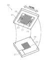
図3は、本発明の実施の形態1に係る車輪速センサ1の発電部20の一構成例を示す模式的斜視図であり、発電部20のエレクトレット21及び電極22をMEMS(Micro Electro Mechanical System)とした場合の構成例を示してある。発電部20は、中央に略長方形の開口が形成された枠部24を有しており、枠部24の開口内には略長方形の板状をなす移動部23がばね部25により開口内を移動可能に支持されている。枠部24の開口は略長方形をなしており、移動部23は開口の長手方向に往復して移動することができるよう、移動部23は移動方向に関する両端面がそれぞればね部25を介して枠部24の開口の内面に接続される態様で支持されている。
FIG. 3 is a schematic perspective view showing a configuration example of the
移動部23には、その一面に複数のエレクトレット21が移動部23の移動方向に並べて配されている。各エレクトレット21は、細長い長方形状をなしており、その長手方向が移動部23の移動方向に対して略垂直となるように、移動部23の一面に並べて配されている。即ちエレクトレット21は、移動部23、枠部24及びばね部25により移動可能に支持されており、これらの各部はエレクトレット21の支持部材を構成している。
A plurality of
また発電部20は、枠部24と略同じ大きさの略長方形状をなす基板部26を有している。基板部26の一面には、略中央に金属製の電極22が配されている。電極22は、移動部23に配されたエレクトレット21と同様に、細長い長方形状の電極部分を複数並べた構成をなしており、これら複数の電極部分の両端を電気的に接続した構成である。電極22は基板部26に設けられた回路部27に接続されており、回路部27には外部回路との接続のための接続端子などが設けられている。
Further, the
発電部20の枠部24は基板部26に接続固定され、これにより枠部24にばね部25を介して支持された移動部23のエレクトレット21と、基板部26に配された電極22とが対向配置される。なお、この状態においてエレクトレット21及び電極22は所定の間隙を隔てて対向配置され、エレクトレット21及び電極22が直接に接触することはない。また、エレクトレット21は、移動部23、ばね部25、枠部24、基板部26及び回路部27を介して接地電位に接続される。
The
この構成により、車輪速センサ1が車輌に取り付けられ、車輌の走行に伴って車体が振動し、車輪速センサ1が振動した場合には、発電部20の移動部23が振動に伴って枠部24の開口内で往復運動する(図3中の白抜き矢印参照)。移動部23の往復運動によって、移動部23に設けられたエレクトレット21が基板部26に設けられた電極22に対して相対移動し、エレクトレット21及び電極22が対向する部分の面積が増減する。これにより、電極22の誘導電荷が増減し、発電部20による発電が行われ、車輪速センサ1の無線通信部11及び検知部12へ電力供給が行われる。
With this configuration, when the
なお、発電部20による発電効率を高めるために、車輪速センサ1の車輌における取り付けは、発電部20の移動部23が往復して移動する方向が、車輌において最も振動が生じやすい方向となるように、車体への取り付け位置及び方向等を決定することが望ましい。また、図3に示す構造の発電部20を車輪速センサ1に複数搭載し、各発電部20の移動部23の移動方向がそれぞれ異なる方向となるように搭載位置及び方向を決定してもよい。また、車輌ではショックアブゾーバーにより車室内の振動を低減させているため、車輪速センサ1は車輌中のショックアブゾーバーによる振動低減の効果が及ばない箇所に取り付けることが望ましい。
In order to increase the power generation efficiency of the
以上の構成の実施の形態1に係る車輪速センサ1は、検知部12にて検知した車輪速を無線送信部11が無線によりECU5へ送信する構成とすることにより、車輪速センサ1とECU5とを信号送信のためのケーブルを介して接続する必要がない。また、車輪速センサ1に発電部20を設け、車輌の走行に伴う振動により発電を行う構成とすることにより、外部からの電力供給なしに無線送信部11及び検知部12等を動作させることができるため、車輪速センサ1と車輌の電源とを電力供給用のケーブルを介して接続する必要がない。よって、車輪速センサ1にケーブルを接続する必要はなく、車輪速センサの車輌への取り付け自由度を高めることができる。また車輌中に配されるケーブルの数を削減できるため、車輌の軽量化などに寄与することができる。
The
また、発電部20がエレクトレット21及び電極22を相対移動させることによって電力を発生させる静電誘導方式の発電を行う構成とすることにより、車輌の振動エネルギーを基に発電を行うことができ、エレクトレット21及び電極22は小型化が容易であるため、車輪と共に回転するリング磁石及びコイルなどを用いる電磁誘導方式の発電と比較して、小型で高効率の発電が可能な発電部20を実現でき、車輪速センサ1を小型化することができる。
In addition, since the
なお、本実施の形態においては、車輌に搭載されるセンサとして車輪速センサ1を例に説明を行ったが、これに限るものではなく、例えば温度センサ、ガスセンサ、光センサ又は加速度センサ等の他の車載センサに同様の構成を適用することができる。また、車輪速センサ1をABSのために用いる構成としたが、これに限るものではなく、他の車輌制御に用いる構成であってもよい。
In the present embodiment, the
また、車輪速センサ1からECU5へ一方向の無線通信を行う構成としたが、これに限るものではなく、車輪速センサ1及びECU5が双方向の無線通信を行う構成としてもよい。また、無線送信部11による車輪速センサ1からECU5への無線送信は、電波によるものでなく、磁気結合、赤外線などの光又は超音波等の手段により行ってもよい。また、発電部20の構成は図3に示したものに限らず、その他の構成であってもよい。図3においてはエレクトレット21を電極22に対して移動させる構成としたが、これに限らず、電極22をエレクトレット21に対して移動させる構成としてもよい。
Moreover, although it was set as the structure which performs one-way radio | wireless communication from the
(変形例)
図4は、本発明の実施の形態1の変形例に係る車輪速センサ1aの構成を示すブロック図である。変形例に係る車輪速センサ1aは、上述の実施の形態1に係る車輪速センサ1に蓄電部30を加えた構成である。蓄電部30は、二次電池又はコンデンサ等で構成され、発電部20が発電した電力を蓄積することができる。また車輌が走行していないなどで車輪速センサ1aが振動せず、発電部20による発電を行うことができない場合には、蓄電部30に蓄積した電力を無線送信部11及び検知部12等へ供給し、蓄積した電力が尽きるまでの間は車輪速センサ1の各部を動作させることができる。
(Modification)
FIG. 4 is a block diagram showing a configuration of a
(実施の形態2)
図5は、本発明の実施の形態2に係る車輪速センサ201の構成を示すブロック図である。上述の実施の形態1に係る車輪速センサ1は、エレクトレット21及び電極22による静電誘導方式の発電を行う構成である。これに対して実施の形態2に係る車輪速センサ201は、圧電体221による圧電方式の発電を行う構成である。
(Embodiment 2)
FIG. 5 is a block diagram showing a configuration of the
実施の形態2に係る車輪速センサ201の発電部220は、圧電体221を有している。圧電体221は、加えられた圧力に比例して電荷が発生する圧電効果を利用し、振動に伴う圧力のエネルギーを電圧に変換する素子である。車輪速センサ201が車輌に取り付けられ、車輌の走行に伴って車体が振動し、車輪速センサ201が振動した場合、発電部220の圧電体221には振動による圧力が加えられ、圧電体221は圧力に応じた電圧を発生させる。よって発電部220は、圧電体221により発電を行うことができ、無線送信部11及び検知部12等へ電力供給を行うことができる。
The
以上の構成の実施の形態2に係る車輪速センサ201は、圧電体221へ振動による圧力を加えて電力を発生させる圧電方式の発電を発電部220が行う構成とすることにより、車輌の振動エネルギーを基に発電を行うことができ、圧電体221は小型化が容易であるため、車輪と共に回転するリング磁石及びコイルなどを用いる電磁誘導方式の発電と比較して、小型で高効率の発電が可能な発電部220を実現でき、車輪速センサ201を小型化することができる。
The
なお、実施の形態2に係る車輪速センサ201のその他の構成は、実施の形態1に係る車輪速センサ1の構成と同様であるため、同様の箇所には同じ符号を付して詳細な説明を省略する。
In addition, since the other structure of the
1、1a 車輪速センサ(車載センサ)
5 ECU(他の装置)
11 無線送信部
12 検知部
13 磁石
14 ホールIC
20 発電部
21 エレクトレット
22 電極
30 蓄電部
51 無線受信部
201 車輪速センサ(車載センサ)
220 発電部
221 圧電体
1, 1a Wheel speed sensor (vehicle sensor)
5 ECU (other devices)
11
DESCRIPTION OF
220
Claims (5)
前記車輌の振動により発電を行う発電部と、
該発電部からの電力供給により動作し、前記検知部が検知した車輪速を無線により他の装置へ送信する無線送信部と
を備えること
を特徴とする車輪速センサ。 A wheel speed sensor mounted on a vehicle and provided with a detection unit for detecting the wheel speed of the vehicle,
A power generation unit that generates power by vibration of the vehicle;
A wheel speed sensor, comprising: a wireless transmission unit that operates by supplying power from the power generation unit and that wirelessly transmits the wheel speed detected by the detection unit to another device.
電荷を保持した帯電体と、
該帯電体に対向して配された電極と、
前記帯電体及び前記電極の一方が、前記車輌の振動によって他方に対して相対的に移動できるように、前記帯電体及び前記電極を支持する支持部材と
を有し、
前記帯電体及び前記電極の静電誘導により発電を行うようにしてあること
を特徴とする請求項1に記載の車輪速センサ。 The power generation unit
A charged body holding a charge;
An electrode disposed opposite the charged body;
A support member that supports the charged body and the electrode so that one of the charged body and the electrode can move relative to the other by vibration of the vehicle;
The wheel speed sensor according to claim 1, wherein power generation is performed by electrostatic induction of the charged body and the electrode.
前記車輌の振動による前記圧電体の振動によって発電を行うようにしてあること
を特徴とする請求項1に記載の車輪速センサ。 The power generation unit has a piezoelectric body,
The wheel speed sensor according to claim 1, wherein power generation is performed by vibration of the piezoelectric body caused by vibration of the vehicle.
を特徴とする請求項1乃至請求項3のいずれか1つに記載の車輪速センサ。 The wheel speed sensor according to any one of claims 1 to 3, further comprising a power storage unit that stores electric power generated by the power generation unit.
前記車輌の振動により発電を行う発電部と、
該発電部からの電力供給により動作し、前記検知部が検知した前記車輌の状態を無線により他の装置へ送信する無線送信部と
を備えること
を特徴とする車載センサ。 An in-vehicle sensor that is mounted on a vehicle and includes a detection unit that detects the state of the vehicle,
A power generation unit that generates power by vibration of the vehicle;
A vehicle-mounted sensor, comprising: a wireless transmission unit that operates by supplying power from the power generation unit and that wirelessly transmits the state of the vehicle detected by the detection unit to another device.
Priority Applications (1)
| Application Number | Priority Date | Filing Date | Title |
|---|---|---|---|
| JP2009020602A JP2010175475A (en) | 2009-01-30 | 2009-01-30 | Wheel speed sensor and on-board sensor |
Applications Claiming Priority (1)
| Application Number | Priority Date | Filing Date | Title |
|---|---|---|---|
| JP2009020602A JP2010175475A (en) | 2009-01-30 | 2009-01-30 | Wheel speed sensor and on-board sensor |
Publications (1)
| Publication Number | Publication Date |
|---|---|
| JP2010175475A true JP2010175475A (en) | 2010-08-12 |
Family
ID=42706584
Family Applications (1)
| Application Number | Title | Priority Date | Filing Date |
|---|---|---|---|
| JP2009020602A Pending JP2010175475A (en) | 2009-01-30 | 2009-01-30 | Wheel speed sensor and on-board sensor |
Country Status (1)
| Country | Link |
|---|---|
| JP (1) | JP2010175475A (en) |
Cited By (8)
| Publication number | Priority date | Publication date | Assignee | Title |
|---|---|---|---|---|
| WO2012073465A1 (en) * | 2010-12-03 | 2012-06-07 | 富士フイルム株式会社 | Electrostatic-induction type conversion element |
| CN102854336A (en) * | 2012-09-17 | 2013-01-02 | 华北电力大学 | Device and method for measuring rotating speed of rotating object by adopting electrostatic sensor |
| KR101369686B1 (en) | 2012-04-30 | 2014-03-04 | 쌍용자동차 주식회사 | Apparatus for battery charging of vehicle and method thereof |
| CN103760378A (en) * | 2014-01-07 | 2014-04-30 | 清华大学 | Electrostatic rotation speed sensor based on electret |
| CN104459187A (en) * | 2014-11-21 | 2015-03-25 | 西安交通大学 | Device and method for measuring rotating speed of large rotating equipment |
| JP2015093608A (en) * | 2013-11-13 | 2015-05-18 | 太平洋工業株式会社 | Tire condition monitoring device |
| CN107000691A (en) * | 2014-12-10 | 2017-08-01 | 欧姆龙株式会社 | The state monitoring apparatus of vehicle and the condition monitoring system of vehicle |
| CN116087556A (en) * | 2023-03-03 | 2023-05-09 | 大陆汽车安全系统(长春)有限公司 | Acceleration sensor, electronic control system and vehicle suspension system |
-
2009
- 2009-01-30 JP JP2009020602A patent/JP2010175475A/en active Pending
Cited By (12)
| Publication number | Priority date | Publication date | Assignee | Title |
|---|---|---|---|---|
| WO2012073465A1 (en) * | 2010-12-03 | 2012-06-07 | 富士フイルム株式会社 | Electrostatic-induction type conversion element |
| JP2012120388A (en) * | 2010-12-03 | 2012-06-21 | Fujifilm Corp | Electrostatic induction type conversion device |
| KR101369686B1 (en) | 2012-04-30 | 2014-03-04 | 쌍용자동차 주식회사 | Apparatus for battery charging of vehicle and method thereof |
| CN102854336A (en) * | 2012-09-17 | 2013-01-02 | 华北电力大学 | Device and method for measuring rotating speed of rotating object by adopting electrostatic sensor |
| JP2015093608A (en) * | 2013-11-13 | 2015-05-18 | 太平洋工業株式会社 | Tire condition monitoring device |
| CN103760378A (en) * | 2014-01-07 | 2014-04-30 | 清华大学 | Electrostatic rotation speed sensor based on electret |
| CN103760378B (en) * | 2014-01-07 | 2017-04-05 | 清华大学 | A kind of electrostatic speed probe based on electret |
| CN104459187A (en) * | 2014-11-21 | 2015-03-25 | 西安交通大学 | Device and method for measuring rotating speed of large rotating equipment |
| CN107000691A (en) * | 2014-12-10 | 2017-08-01 | 欧姆龙株式会社 | The state monitoring apparatus of vehicle and the condition monitoring system of vehicle |
| EP3210840A4 (en) * | 2014-12-10 | 2018-02-21 | Omron Corporation | Vehicle state monitoring device and vehicle state monitoring system |
| US10227058B2 (en) | 2014-12-10 | 2019-03-12 | Omron Corporation | Vehicle state monitoring device and vehicle state monitoring system |
| CN116087556A (en) * | 2023-03-03 | 2023-05-09 | 大陆汽车安全系统(长春)有限公司 | Acceleration sensor, electronic control system and vehicle suspension system |
Similar Documents
| Publication | Publication Date | Title |
|---|---|---|
| JP2010175475A (en) | Wheel speed sensor and on-board sensor | |
| JP4408919B2 (en) | Power generation device, electric device equipped with power generation device, and communication device equipped with power generation device | |
| US7525205B2 (en) | Electric power generator | |
| JP2008086190A (en) | Power generator, electrical equipment mounted with the same, and communications device mounted with the equipment | |
| US9233693B2 (en) | Tire sensing system | |
| JP6249203B2 (en) | Power generation vibration sensor, tire and electric device using the same | |
| KR101740690B1 (en) | Energy harvester for vehicle tire | |
| US20080284258A1 (en) | Chassis Component | |
| US20050082912A1 (en) | Power supply device for a tire-pressure sensor | |
| JP3790255B1 (en) | ENERGY CONVERSION DEVICE, MOBILE BODY HAVING THE SAME, AND ENERGY CONVERSION SYSTEM | |
| JP2008526596A (en) | Tire module and pneumatic tire having tire module | |
| JP4198817B2 (en) | Tire internal condition measuring instrument | |
| CN105408164B (en) | Coil with the vehicle side being incorporated into speed changer oil sump is used for the wireless charging device of vehicle battery charging | |
| CN105745833A (en) | Vibration power generator | |
| JP2000278923A (en) | Tire mounting power generator and tire sensor module | |
| WO2014077056A1 (en) | Contactless electricity supply system | |
| US20190319524A1 (en) | Power generation element and smart key | |
| JP2014169054A (en) | On-vehicle electric equipment device | |
| US6989609B2 (en) | Method and apparatus for supplying energy to sensors | |
| JP6409357B2 (en) | Vibration reduction unit, vibration reduction support device, and vibration reduction method | |
| CN1971082A (en) | Shock absorber and vehicle suspension system having same | |
| US20110114397A1 (en) | Power module and vehicle having the same | |
| CN108621964A (en) | Armrest box | |
| JPWO2013057897A1 (en) | Vibration generator, rotating body and communication device | |
| JP2006115662A (en) | Energy conversion device and movable body equipped therewith |