JP2012185189A - Sample holder - Google Patents
Sample holder Download PDFInfo
- Publication number
- JP2012185189A JP2012185189A JP2012148704A JP2012148704A JP2012185189A JP 2012185189 A JP2012185189 A JP 2012185189A JP 2012148704 A JP2012148704 A JP 2012148704A JP 2012148704 A JP2012148704 A JP 2012148704A JP 2012185189 A JP2012185189 A JP 2012185189A
- Authority
- JP
- Japan
- Prior art keywords
- sample
- elastic member
- sample holder
- holding
- sample container
- Prior art date
- Legal status (The legal status is an assumption and is not a legal conclusion. Google has not performed a legal analysis and makes no representation as to the accuracy of the status listed.)
- Granted
Links
Images


Landscapes
- Investigating, Analyzing Materials By Fluorescence Or Luminescence (AREA)
- Sampling And Sample Adjustment (AREA)
- Investigating Or Analysing Materials By Optical Means (AREA)
- Photometry And Measurement Of Optical Pulse Characteristics (AREA)
Abstract
Description
本発明は、試料容器内の試料に励起光を照射することによって発生する被測定光を観測する積分球に対して着脱自在な試料ホルダに関するものである。 The present invention relates to a sample holder that is detachable from an integrating sphere for observing light to be measured generated by irradiating a sample in a sample container with excitation light.
被測定光が放射状に発生する試料の光強度を測定するために積分球が用いられている。積分球は、球状の本体内壁に高拡散反射粉末が塗布されていて、試料から被測定光が放射状に発生すると、その高拡散反射粉末により被測定光が多重拡散反射される。そして、拡散反射された光が光検出器に入射し、その出力信号が光強度計に導かれて被測定光の強度が測定される。そのような積分球は下記特許文献1〜3に開示されている。
積分球で測定される試料は、光学セルと呼ばれるガラス製の反応管(試料容器)内に収容され、このセルは、試料ホルダに取り付けられた状態で積分球内に挿入される。この試料ホルダは、例えば、特許文献4に開示されているように、2分割されている。そして、一方の試料ホルダ半部と他方の試料ホルダ半部とでセルより延在する棒状の枝管を挟み込み、試料ホルダ半部同士をネジによって連結することで、試料ホルダにセルが固定され、また、ネジを外すことで、試料ホルダからセルを外すことができる。
An integrating sphere is used to measure the light intensity of the sample in which the light to be measured is generated radially. In the integrating sphere, a high diffuse reflection powder is applied to the spherical inner wall of the main body, and when the light to be measured is generated radially from the sample, the light to be measured is multiple diffusely reflected by the high diffuse reflection powder. Then, the diffusely reflected light is incident on the photodetector, and the output signal is guided to the light intensity meter to measure the intensity of the light to be measured. Such integrating spheres are disclosed in the following
The sample measured by the integrating sphere is accommodated in a glass reaction tube (sample container) called an optical cell, and this cell is inserted into the integrating sphere in a state of being attached to the sample holder. This sample holder is divided into two parts as disclosed in Patent Document 4, for example. And the cell is fixed to the sample holder by sandwiching a rod-shaped branch pipe extending from the cell between one sample holder half and the other sample holder half, and connecting the sample holder halves with screws, Moreover, a cell can be removed from a sample holder by removing a screw.
しかしながら、様々な種類の試料を積分球によって短時間で測定する場合、試料ホルダにセルを素早く取り付ける必要があるが、従来にあっては、試料ホルダにセルを取り付ける手段としてネジが利用されているので、ネジ山の潰れによって、セルを試料ホルダに確実に固定することができない虞があった。 However, when various types of samples are measured with an integrating sphere in a short time, it is necessary to quickly attach the cell to the sample holder. Conventionally, screws are used as means for attaching the cell to the sample holder. Therefore, there is a possibility that the cell cannot be securely fixed to the sample holder due to the crushing of the screw thread.
本発明は、保持部に対する試料容器の取付けを確実に行うようにした試料ホルダを提供することを目的とする。 An object of the present invention is to provide a sample holder in which the sample container is securely attached to the holding portion.
本発明は、試料容器内の試料によって発生する被測定光を観測する積分球に対して着脱自在に取り付けられる試料ホルダにおいて、
試料容器を挟持する弾性部材を有する保持部と、
保持部が嵌め込まれることで保持部を加圧する固定部材と、を備え、
固定部材による加圧により、弾性部材が試料容器を押さえつけて保持部が試料容器を挟持することを特徴とする。
The present invention provides a sample holder that is detachably attached to an integrating sphere for observing light to be measured generated by a sample in a sample container.
A holding part having an elastic member for sandwiching the sample container;
A fixing member that pressurizes the holding part by fitting the holding part,
The elastic member presses the sample container by pressurization by the fixing member, and the holding unit holds the sample container.
また、保持部は積分球に取付けられるフランジ部を有し、弾性部材は、フランジ部よりも上方に位置すると好適である。 In addition, it is preferable that the holding portion has a flange portion attached to the integrating sphere, and the elastic member is positioned above the flange portion.
また、保持部は、第1の半部と第2の半部とからなり、弾性部材は、第1の半部に設けられた第1の弾性部材と、第2の半部に設けられた第2の弾性部材とからなり、第1の弾性部材と第2の弾性部材とで試料容器を挟持すると好適である。 In addition, the holding portion includes a first half and a second half, and the elastic member is provided in the first elastic member provided in the first half and the second half. Preferably, the sample container is composed of a second elastic member, and the sample container is sandwiched between the first elastic member and the second elastic member.
また、保持部は、積分球内に挿入される側の第1の端部と、積分球の外側に配置される第2の端部とを有し、固定部材が保持部を加圧する位置は、第1の弾性部材の中心位置及び第2の弾性部材の中心位置よりも保持部の第1の端部に近いと好適である。 The holding part has a first end part on the side inserted into the integrating sphere and a second end part arranged outside the integrating sphere, and the position where the fixing member presses the holding part is The center position of the first elastic member and the center position of the second elastic member are preferably closer to the first end of the holding portion.
また、保持部の外面には、固定部材に嵌め込まれて押圧される張り出し部が設けられ、固定部材の内周面には、張り出し部を押圧する凸部が形成され、保持部の内面には、試料容器を挟持する弾性部材が設けられ、保持部を加圧する方向において、弾性部材と張り出し部とが対向して配置されていると好適である。 In addition, the outer surface of the holding portion is provided with an overhanging portion that is fitted into the fixing member and pressed, and a convex portion that presses the overhanging portion is formed on the inner peripheral surface of the fixing member. It is preferable that an elastic member for holding the sample container is provided and the elastic member and the overhanging portion are arranged to face each other in the direction in which the holding portion is pressurized.
また、張り出し部には、固定部材への挿入側にテーパ部が形成されていると好適である。 Further, it is preferable that the projecting portion is formed with a tapered portion on the insertion side to the fixing member.
本発明によれば、保持部に対する試料容器の取付けを確実に行うことができる。 According to the present invention, the sample container can be reliably attached to the holding portion.
以下、図面を参照しつつ本発明に係る試料ホルダの好適な実施形態について詳細に説明する。 Hereinafter, a preferred embodiment of a sample holder according to the present invention will be described in detail with reference to the drawings.
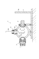
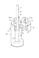
図1に示されるように、光検出装置1は、試料に励起光を照射することによって発生する被測定光を観測する積分球2と、積分球2にネジによって着脱可能に取り付けられる試料ホルダ4,6と、励起光を積分球2内に導入するための励起光用光ファイバホルダ3と、被測定光を取得するための図示しない光検出光用ファイバホルダと、2つの接地面7a、7bを有するL字形の架台7とを備えている。そして、積分球2は、取り付けねじ8によって架台7に取り付けられている。
As shown in FIG. 1, an
試料ホルダ4に保持した試料を測定する場合、励起光の光軸Lが鉛直線に沿うように、架台7の接地面7aを下にした状態で光検出装置1をセットする。ここで、試料ホルダ4は、主として固形試料、粉末試料などの測定に使用され、これらの試料Sはガラス等の基板に塗布された形態で試料ホルダ4に保持されても良いし、シャーレ等の容器に収容された形態で試料ホルダ4に保持されても良い。
When measuring the sample held in the sample holder 4, the
励起光用光ファイバホルダ3に取り付けられている光ファイバ(図示しない)は、図示しない励起光源に接続されている。励起光源から出射された励起光は光ファイバを通って励起光用光ファイバホルダ3のレンズに導かれる。その励起光は、光軸Lに沿って積分球2内に導かれ、試料ホルダ4に載置されている試料Sに照射される。
An optical fiber (not shown) attached to the excitation light
励起光が試料Sに照射されると、その励起光を吸収した試料Sから被測定光が発生する。その被測定光は、積分球2の内壁にコーティングされた硫酸バリウム等の拡散反射剤により多重拡散反射される。この拡散反射された被測定光は、図示しない光検出用光ファイバホルダに取り付けられている光ファイバに入射される。この光ファイバは光検出器、例えば、マルチチャンネル光検出器(図示しない)に接続されている。従って、被測定光は光ファイバを通ってマルチチャンネル光検出器に導かれ、マルチチャンネル光検出器が検出した測定データはデータ処理され、モニタに被測定光の強度の測定値が表示される。 When the sample S is irradiated with excitation light, light to be measured is generated from the sample S that has absorbed the excitation light. The measured light is multiple diffusely reflected by a diffuse reflector such as barium sulfate coated on the inner wall of the integrating sphere 2. The diffusely reflected measurement light is incident on an optical fiber attached to an optical fiber holder for light detection (not shown). The optical fiber is connected to a photodetector, for example, a multichannel photodetector (not shown). Therefore, the light to be measured is guided to the multi-channel photodetector through the optical fiber, the measurement data detected by the multi-channel photodetector is processed, and the measured value of the intensity of the light to be measured is displayed on the monitor.
試料ホルダ6は、主として色素等が溶解された液体試料Rの測定に使用され、試料Rは、光学セル9と呼ばれるガラス製の容器内に収容された形態で試料ホルダ6に保持される。また、光学セル9は、試料Rが収容される四角柱形状の中空のセル本体9aと、セル本体9aから管状に延在する棒状の枝管9bとからなる。この試料ホルダ6は、積分球2に設けられた台座部2aにネジを介して固定され、試料Rを測定する場合、励起光の光軸Lが水平線に沿うように、架台7の接地面7bを下にした状態で光検出装置1をセットする。
The
励起光用光ファイバホルダ3に取り付けられている光ファイバ(図示せず)から出射された励起光を、光学セル(試料容器)9内に収容されている溶液試料Rに照射すると、その励起光を吸収した溶液試料Rから被測定光が発生する。その被測定光は、積分球2の内壁にコーティングされた硫酸バリウム等の拡散反射剤により多重拡散反射される。この拡散反射された被測定光は、図示しない光検出用光ファイバホルダに取り付けられている光ファイバに入射される。この光ファイバは光検出器、例えば、マルチチャンネル光検出器(図示しない)に接続されている。従って、被測定光は光ファイバを通ってマルチチャンネル光検出器に導かれ、マルチチャンネル光検出器が検出した測定データはデータ処理され、モニタに被測定光の強度の測定値が表示される。
When excitation light emitted from an optical fiber (not shown) attached to the
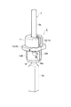
次に、試料ホルダ6について詳細に説明する。
Next, the
図2〜図4に示されるように、試料ホルダ6は、ガラス製の光学セル(試料容器)9の枝管9bを挟持する保持部10と、保持部10の外面10aから保持部10の中心へ向かって内側方向に保持部10を加圧して、保持部10によりセル9の枝管9bを挟持する金属(例えばアルミニウム)製の固定部材11とからなる。
As shown in FIGS. 2 to 4, the
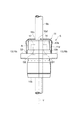
円筒状の保持部10は、セル9の枝管9bの保持を可能にする第1の半部12と第2の半部13とからなり、第1の半部12と第2の半部13は略同一形状をなし、各半部本体12P,13Pは、金属(例えばアルミニウム)によって形成されている。第1の半部12は、シリコン樹脂からなる第1の弾性部材14が半部本体12Pの上半分に固定された上側部12Aと、光拡散反射材(例えば、スペクトラロン(Labsphere 社の商品名))からなる光反射部15が半部本体12Pの下側に固定された下側部12Bと、上側部12Aと下側部12Bとの間に形成された第1のフランジ部16とを有している。
The cylindrical holding
同様に、第2の半部13は、シリコン樹脂からなる第2の弾性部材17が半部本体13Pの上半分に固定された上側部13Aと、光拡散反射材(例えば、スペクトラロン(Labsphere 社の商品名))からなる光反射部18が半部本体13Pの下側に固定された下側部13Bと、上側部13Aと下側部13Bとの間に形成された第2のフランジ部19とを有している。なお、第1の半部12と第2の半部13とを突き合わせたときに、保持部10の中央には、セル9の枝管9bと略同じ径の貫通孔10Aが形成される(図6参照)。
Similarly, the
第1の半部12の上側部12Aに形成された四角柱形状の凹部20a内に第1の弾性部材14が収容されている。この第1の弾性部材14は、矩形の樹脂製ベース板21に接着固定され、ベース板21は、上側部12Aの外側から凹部20aまで達するネジ22によって凹部20aの底壁面に固定されている。ネジ22の採用により、第1の弾性部材14は、交換可能になっている。さらに、第1の半部12には、凹部20aから下端に向かって延在する半円柱形状の凹部20bが形成されている。同様に、第2の半部13の上側部13Aに形成された四角柱形状の凹部23a内に第2の弾性部材17が収容されている。この第2の弾性部材17は、矩形の樹脂製ベース板24に接着固定され、ベース板24は、上側部13Aの外側から凹部23aまで達するネジ25によって凹部23aの底壁面に固定されている。ネジ25の採用により、第2の弾性部材17は、交換が可能になっている。さらに、第2の半部13には、凹部23aから下端に向かって延在する半円柱形状の凹部23bが形成されている。
The first
第1の半部12の下側部12Bの下端に形成された凹部26内に光反射部15の上部が挿入され、光反射部15は、下側部12Bの外側から凹部26まで達するネジ(図示せず)によって下側部12Bに固定され、ネジの採用により、光反射部15は、交換可能になっている。同様に、第2の半部13の下側部13Bの下端に形成された凹部28内に光反射部18の上部が挿入され、光反射部18は、下側部13Bの外側から凹部28まで達するネジ18aによって下側部13Bに固定され、ネジ18aの利用により、光反射部18は、交換可能になっている。
The upper part of the
第1の半部12の合わせ面12aには、円柱状の突起部30が設けられ、第2の半部13の合わせ面13aには、円柱状の窪み部31が設けられている。そして、第1の半部12の合わせ面12aと第2の半部13の合わせ面13aとを突き合わせたときに、突起部30が窪み部31内に入り込み、第1の半部12に対する第2の半部13の位置ズレが防止され、第1の弾性部材14と第2の弾性部材17とでセル9の枝管9bを確実に挟持することができる。
The
弾性部材14,17の採用は、ガラスやプラスチックなどの損傷し易い材料で成形されている光学セル(試料容器)9を保持部10に固定する場合に適している。さらには、弾性部材14,17がセル9の枝管9bにしっかりと押し付けられるので、保持部10にセル9を確実に固定させることができる。
The use of the
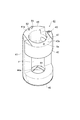
図2〜図5に示されるように、第1の半部12と第2の半部13との突き合わせ状態及び第1の弾性部材14と第2の弾性部材17とによるセル9の枝管9bの挟持状態を維持させるために、キャップ(固定部材)11が利用されている。このキャップ11は、保持部10を覆うように保持部10に被せられる。キャップ11の頂壁11aには枝管9bが挿通する開口部11bが形成され、キャップ11の外周壁11cには、開口部11bから外周壁11cの遊端まで延在する略L字状の切欠き部32が形成されている。そして、切欠き部32の幅Wは、枝管9bの直径Dより大きくなっている。よって、セル9の枝管9bをキャップ11の切欠き部32から差し込むことができるので、キャップ11を保持部10に装着する際の作業性が良くなる。
As shown in FIGS. 2 to 5, the
図4及び図5に示されるように、キャップ11の切欠き部32からセル9の枝管9bを差し込み、キャップ11の開口部11bまで枝管9bを到達させる。その後、枝管9bに沿ってキャップ11を押し下げることにより、V字状に開いた第1の半部12と第2の半部13とが突き合わされ、弾性部材14,17がセル9の枝管9bに押し付けられる。この場合、キャップ11は、保持部10の外周壁11cから保持部10の内側に向かってすなわち貫通孔10A(図6参照)を通る中心軸線Yに向かって保持部10を加圧する。
As shown in FIGS. 4 and 5, the
また、キャップ11の内周面11dの下端には、保持部10の外面10aに形成されたリング状の張り出し部10bに当接するC字状の凸部33が設けられている。この凸部33は保持部10の張り出し部10bの表面に押し付けられるので、キャップ11の外れ防止に寄与し、弾性部材14,17はセル9の枝管9bにしっかりと押し付けられる。
In addition, a C-shaped
さらに、保持部10において、積分球2内に挿入される側を第1の端部10cとし、積分球2の外側に配置される側を第2の端部10dとすると、キャップ11が保持部10を加圧する位置すなわちキャップ11の凸部33が保持部10の張り出し部10bを押圧する位置は、第1の弾性部材14の中心位置及G1及び第2の弾性部材17の中心位置G2よりも保持部10の第1の端部10cに近づいている。
Further, in the holding
したがって、積分球2内に挿入される第1の端部10c側で保持部10がキャップ11により加圧されているので、第1の半部12と第2の半部13とを第1の端部10c側で密着させることができる。その結果として、第1の端部10c側における第1の半部12と第2の半部13との合わせ部分の隙間を無くすことができ、これによって、積分球2内の光が保持部10から漏れ出すことが防止され、測定誤差の防止が図られている。
Accordingly, since the holding
図4に示されるように、キャップ11の内周面11dと、保持部10の外周面10aとの間に隙間Aが設けられている。このような隙間Aによって、図5に示されるように、第1の半部12と第2の半部とで保持部10がV字状に開いた状態で、張り出し部10bの上端に設けられたテーパ部10eまでキャップ11を上から被せることができる。この状態から、矢印B方向にキャップ11を押し下げることによって、キャップ11の凸部33が保持部10の張り出し部10bを内側に向けて押圧しながら、V字状に開いた第1の半部12の合わせ面12aと第2の半部13の合わせ面13aとが突き合わされる。したがって、保持部10に対してキャップ11を上から押し付けるようにして嵌め込むことができ、キャップ11のワンタッチ装着が可能になる。
As shown in FIG. 4, a gap A is provided between the inner
図2に示されるように、保持部10の第1の半部12の頂部には、きのこ形状の抜け止めピン(抜け止め手段)35が突出している。キャップ11の頂壁11aには、開口部11bから延びてピン35の通過を可能にしたキャップ回り止め用の溝部36が形成されている。図13に示されるように、矢印C方向にキャップ11を回すと、この溝部36内にピン35が入り込み、ピン35のヘッド部35aによって、キャップ11が保持部10から抜け落ちることない。
As shown in FIG. 2, a mushroom-shaped retaining pin (a retaining means) 35 protrudes from the top of the
この試料ホルダ6には、保持部10の外周面10aから保持部10の内側に向かって保持部10を加圧して、保持部10によりセル9の枝管9bを挟持するキャップ11が採用されている。このようにキャップ11は、保持部10に対して装着し易く、保持部10に対するセル9の取付け作業性を良好にしている。しかも、保持部10の外周面10aから内側に向かって保持部10を加圧する力は、しっかりとセル9を保持部10に固定させるのに最適である。そして、試料ホルダ6にセル9を素早く取り付けることができので、様々な種類の試料を積分球2によって短時間で測定することができる。
The
前述した固定部材として採用されているキャップに代えて、金属又は樹脂からなる弾性材料によって成形された帯状の締結バンド又はクリップを利用してもよい。 Instead of the cap employed as the fixing member described above, a band-shaped fastening band or clip formed of an elastic material made of metal or resin may be used.
前述した試料ホルダ6と光学セル9との相対的な位置関係を調整するための試料ホルダ用治具40について詳細に説明する。
The
図7〜図9に示されるように、治具40は、保持部10の第1の半部12が上面41aに載置される治具本体(第1の部材)41と、保持部10の第2の半部13が上面42aに載置される開閉アーム(第2の部材)42と、治具本体41に対して開閉アーム42を水平方向に開閉させるために、治具本体41の上端に開閉アーム42の端部を連結するヒンジ部43とを備えている。
7 to 9, the
半円筒状の治具本体41のセル収容空間Pの下端側において、治具本体41には、セル本体9aの嵌り込みを予定した矩形の穴44aを有する位置調整板44が固定され、この穴44a内にセル本体9aが入り込むことで、試料ホルダ6と光学セル9との相対的な位置関係が調整される。また、治具本体41の下端には円形の底板45がネジ止めされ、セル本体9aの底面は底板45上に載置される。
On the lower end side of the cell housing space P of the semi-cylindrical jig
治具本体41の上面41aには、保持部10の第1の半部12に設けられた第1のフランジ部16が嵌り込む第1の位置決め用凹部46が形成されている。開閉アーム42の上面42aには、保持部10の第2の半部13に設けられた第2のフランジ部19が嵌り込む第2の位置決め用凹部47が形成されている。凹部46,47内にフランジ部16,19を上から嵌め込むことによって、治具40と試料ホルダ6の保持部10との相対的な位置調整がなされる。
A
このように、治具40の上面41a,42aに第1及び第2の位置決め用凹部46,47を形成することは、保持部10の自重及び第1及び第2のフランジ部16,19の有効活用を図ることができる。さらに、フランジ部16,19は、治具40の上面41a,42aに載置される第1及び第2の半部12,13の着座安定性を高めている。
As described above, the formation of the first and second positioning recesses 46 and 47 on the
図10に示されるように、第1の位置決め用凹部46において、治具本体41の上面41aには、第1の半部12の第1のフランジ部16の底面に設けられた第1の孔部51(図6参照)内に挿入される第1の落下防止用ピン52が設けられている。同様に、第2の位置決め用凹部47において、開閉アーム42の上面42aには、第2の半部13の第2のフランジ部19の底面に設けられた第2の孔部53(図6参照)内に挿入される第2の落下防止用ピン54が設けられている。
As shown in FIG. 10, in the
そして、治具40の第1及び第2の位置決め用凹部46,47内に第1及び第2の半部12,13の第1及び第2のフランジ部16,19を上から嵌め込むことによって、第1の落下防止用ピン52が第1のフランジ部16の孔部51内に入り込み、第2の落下防止用ピン54が第1のフランジ部19の孔部53内に入り込む。このような構成によって、図11に示されるように、治具本体41に第1の半部12を載せ、開閉アーム42に第2の半部13を載せた状態で、開閉アーム42を水平方向に開いた場合でも、治具本体41及び開閉アーム42から第1及び第2の半部12,13が落下することなく、第1及び第2の半部12,13の自重を利用して、治具本体41及び開閉アーム42に第1及び第2の半部12,13を確実に載置させることができる。
Then, the first and
さらに、治具本体41の上面41aには、目印として機能するピン55が設けられ、第1の半部12の第1のフランジ部16には、ピン55の挿入を可能にした切欠き溝56(図6参照)が設けられている。このような構成によって、治具本体41の上面41aに第2の半部13が誤装着されることを防止でき、治具本体41及び開閉アーム42に第1及び第2の半部12,13を載置させる際の作業性が良好になる。
Further, a
試料ホルダ6にセル9を取り付ける手順について簡単に説明する。
A procedure for attaching the
図11に示されるように、治具本体41に第1の半部12を載せ、開閉アーム42に第2の半部13を載せ、この状態で、開閉アーム42を水平方向に開く。そして、治具40に設けられた位置調整板44の穴44a内にセル本体9aを上から差し込む(図10参照)。その後、図12に示されるように、開閉アーム42を閉じる。そして、キャップ11の切欠き部32からセル9の枝管9bを差込み、キャップ11の開口部11bまで枝管9bを到達させる。その後、枝管9bに沿ってキャップ11を押し下げることにより、V字状に開いた第1の半部12と第2の半部13とが密着し、弾性部材14,17がセル9の枝管9bに押し付けられる(図4及び図5参照)。そして、矢印C方向(図13参照)にキャップ11を回すと、この溝部36内にピン35が入り込み、試料ホルダ6にセル9をセッティングする作業が完了する(図12参照)。
As shown in FIG. 11, the
前述したように、試料ホルダ用治具40にあっては、治具本体41に対して開閉アーム42を開いた状態で、治具本体41の上面41aに保持部10の第1の半部12を載置することができ、開閉アーム42の上面42aに保持部10の第2の半部12を載置することができるので、保持部10から手を離しても、治具40から保持部10が落下することがない。
As described above, in the
さらに、ヒンジ部43の採用により、治具本体41に対して開閉アーム42を水平方向に開閉させることができるので、治具40にセル9を簡単にセッティングすることができる。このように、治具40は、治具本体41に対して開閉アーム42がヒンジ部43を介して水平方向に回動自在になっているので、保持部10に対する光学セル9の取付け作業を楽に行うことができ、セル9を試料ホルダ6に取り付ける際の手間や時間を大幅に減らすことができる。よって、試料ホルダ6にセル9を素早く取り付けることができ、作業時間の短縮を可能して、様々な種類の試料を積分球2によって短時間で測定することができる。
Furthermore, since the opening /
図14に示されるように、キャップ60の内周面60aには、保持部10の外面10aに形成されたリング状の張り出し部10bの表面に当接する凸部61が設けられている。この凸部61は、キャップ本体62の内周面60aにゴムなどの弾性体63が接着固定されることによって形成されている。そして、キャップ60を保持部10に嵌め込むことによって、弾性体63が保持部10の張り出し部10bに圧着され、保持部10からキャップ60が外れにくくなる。
As shown in FIG. 14, the inner
図15に示されるように、保持部70の第1及び第2の半部71,72の外面には雄ネジ部71a,72aが設けられ、キャップ80の内周面80aには雌ネジ部81が設けられている。そして、第1の半部71と第2の半部72とを突き合わせた状態で、保持部70にキャップ80を嵌め、キャップ80を回すことによって、保持部70の雄ネジ部71a,72aに対してキャップ80の雌ネジ部81が螺合する。
As shown in FIG. 15,
2…積分球、6…試料ホルダ、9…光学セル(試料容器)、9a…セル本体、9b…枝管、10,70…保持部、10a…保持部の外面、10c…保持部の第1の端部、10d…保持部の第2の端部、11,60,80…キャップ(固定部材)、11d…キャップの内周面、12,71…第1の半部、13,72…第2の半部、14…第1の弾性部材、16…第1のフランジ部、17…第2の弾性部材、19…第1のフランジ部、33,61…凸部、35…抜け止めピン(抜け止め手段)、36…溝部、40…試料ホルダ用治具、41…治具本体(第1の部材)、41a…第1の部材の上面、42…開閉アーム(第2の部材)、42a…第2の部材の上面、43…ヒンジ部、46…第1の位置決め用凹部、47…第2の位置決め用凹部、51…第1の孔部、52…第1の落下防止用ピン、53…第2の孔部、54…第2の落下防止用ピン、71a,72a…雄ネジ部、81…雌ネジ部、A…隙間、R…試料。
2 ... integrating sphere, 6 ... sample holder, 9 ... optical cell (sample container), 9a ... cell body, 9b ... branch pipe, 10, 70 ... holding part, 10a ... outer surface of holding part, 10c ... first of holding part , 10d ... second end of the holding part, 11, 60, 80 ... cap (fixing member), 11d ... inner peripheral surface of the cap, 12, 71 ... first half, 13, 72 ... first 2 half, 14 ... 1st elastic member, 16 ... 1st flange part, 17 ... 2nd elastic member, 19 ... 1st flange part, 33, 61 ... convex part, 35 ... Retaining pin ( Retaining means), 36... Groove portion, 40... Sample holder jig, 41... Jig body (first member), 41 a... Upper surface of the first member, 42 .. open / close arm (second member), 42 a ... upper surface of second member, 43 ... hinge portion, 46 ... first positioning recess, 47 ... second positioning recess, 51
Claims (6)
前記試料容器を挟持する弾性部材を有する保持部と、
前記保持部が嵌め込まれることで前記保持部を加圧する固定部材と、を備え、
前記固定部材による加圧により、前記弾性部材が前記試料容器を押さえつけて前記保持部が前記試料容器を挟持することを特徴とする試料ホルダ。 In the sample holder that is detachably attached to the integrating sphere for observing the light to be measured generated by the sample in the sample container,
A holding portion having an elastic member for sandwiching the sample container;
A fixing member that pressurizes the holding part by fitting the holding part,
The sample holder, wherein the elastic member presses the sample container and the holder holds the sample container by pressurization by the fixing member.
前記固定部材が前記保持部を加圧する位置は、前記第1の弾性部材の中心位置及び前記第2の弾性部材の中心位置よりも前記保持部の前記第1の端部に近いことを特徴とする請求項3記載の試料ホルダ。 The holding portion has a first end portion on the side inserted into the integrating sphere, and a second end portion disposed outside the integrating sphere,
The position where the fixing member presses the holding part is closer to the first end of the holding part than the center position of the first elastic member and the center position of the second elastic member. The sample holder according to claim 3.
前記固定部材の内周面には、前記張り出し部を押圧する凸部が形成され、
前記保持部の内面には、前記試料容器を挟持する前記弾性部材が設けられ、前記保持部を加圧する方向において、前記弾性部材と前記張り出し部とが対向して配置されていることを特徴とする請求項1記載の試料ホルダ。 On the outer surface of the holding part, an overhanging part that is fitted and pressed into the fixing member is provided,
On the inner peripheral surface of the fixing member, a convex portion that presses the protruding portion is formed,
The elastic member for sandwiching the sample container is provided on the inner surface of the holding portion, and the elastic member and the overhanging portion are arranged to face each other in a direction in which the holding portion is pressurized. The sample holder according to claim 1.
Priority Applications (1)
| Application Number | Priority Date | Filing Date | Title |
|---|---|---|---|
| JP2012148704A JP5603376B2 (en) | 2012-07-02 | 2012-07-02 | Sample holder |
Applications Claiming Priority (1)
| Application Number | Priority Date | Filing Date | Title |
|---|---|---|---|
| JP2012148704A JP5603376B2 (en) | 2012-07-02 | 2012-07-02 | Sample holder |
Related Parent Applications (1)
| Application Number | Title | Priority Date | Filing Date |
|---|---|---|---|
| JP2007192503A Division JP5036439B2 (en) | 2007-07-24 | 2007-07-24 | Sample holder |
Publications (2)
| Publication Number | Publication Date |
|---|---|
| JP2012185189A true JP2012185189A (en) | 2012-09-27 |
| JP5603376B2 JP5603376B2 (en) | 2014-10-08 |
Family
ID=47015359
Family Applications (1)
| Application Number | Title | Priority Date | Filing Date |
|---|---|---|---|
| JP2012148704A Active JP5603376B2 (en) | 2012-07-02 | 2012-07-02 | Sample holder |
Country Status (1)
| Country | Link |
|---|---|
| JP (1) | JP5603376B2 (en) |
Cited By (2)
| Publication number | Priority date | Publication date | Assignee | Title |
|---|---|---|---|---|
| CN105021434A (en) * | 2015-07-06 | 2015-11-04 | 湖北三江航天红阳机电有限公司 | Preparation method of high-temperature composite material sample |
| CN109477787A (en) * | 2016-07-27 | 2019-03-15 | 浜松光子学株式会社 | Sample container holding member, optical measurement device, and sample container arrangement method |
Citations (17)
| Publication number | Priority date | Publication date | Assignee | Title |
|---|---|---|---|---|
| JPS5435114B2 (en) * | 1972-02-23 | 1979-10-31 | ||
| JPH05113386A (en) * | 1990-11-30 | 1993-05-07 | Shimadzu Corp | Light loss measuring device |
| JPH0623955Y2 (en) * | 1988-02-20 | 1994-06-22 | 株式会社島津製作所 | Sample holding device for integrating sphere measuring device |
| JP2517102B2 (en) * | 1989-03-10 | 1996-07-24 | 日本電子株式会社 | Method for detecting emitted light amount of immunoassay device |
| JPH0989775A (en) * | 1995-07-19 | 1997-04-04 | Kdk Corp | Spectroscopic measuring apparatus and automatic analyzer |
| JPH10142153A (en) * | 1996-11-08 | 1998-05-29 | Kdk Corp | Method and instrument for optical measurement of component in exhalation |
| JP2811565B2 (en) * | 1992-12-30 | 1998-10-15 | 株式会社堀場製作所 | Chemiluminescence detection device and temperature correction method in chemiluminescence reaction |
| JPH11101731A (en) * | 1997-09-29 | 1999-04-13 | Nec Kyushu Ltd | Particle-measuring mechanism |
| JP2939611B2 (en) * | 1996-03-13 | 1999-08-25 | 水道機工株式会社 | Portable water quality testing equipment |
| JP2001013068A (en) * | 1999-06-30 | 2001-01-19 | Kosu:Kk | Densitometer |
| JP2001127034A (en) * | 1999-10-26 | 2001-05-11 | Dainippon Screen Mfg Co Ltd | Board processor |
| JP2004114033A (en) * | 2002-09-04 | 2004-04-15 | Taisei Sangyo Kk | Magnetized active water generator |
| JP2004209419A (en) * | 2003-01-07 | 2004-07-29 | Junichi Yamamoto | Magnetic water activating device |
| JP3577164B2 (en) * | 1996-05-22 | 2004-10-13 | オリンパス株式会社 | Lighting device and color / shape measuring device |
| JP2007033334A (en) * | 2005-07-28 | 2007-02-08 | Hamamatsu Photonics Kk | Sample holder |
| JP2007086031A (en) * | 2005-09-26 | 2007-04-05 | Hamamatsu Photonics Kk | Photodetector and jig for sample holder |
| JP2009031015A (en) * | 2007-07-24 | 2009-02-12 | Hamamatsu Photonics Kk | Sample holder |
-
2012
- 2012-07-02 JP JP2012148704A patent/JP5603376B2/en active Active
Patent Citations (17)
| Publication number | Priority date | Publication date | Assignee | Title |
|---|---|---|---|---|
| JPS5435114B2 (en) * | 1972-02-23 | 1979-10-31 | ||
| JPH0623955Y2 (en) * | 1988-02-20 | 1994-06-22 | 株式会社島津製作所 | Sample holding device for integrating sphere measuring device |
| JP2517102B2 (en) * | 1989-03-10 | 1996-07-24 | 日本電子株式会社 | Method for detecting emitted light amount of immunoassay device |
| JPH05113386A (en) * | 1990-11-30 | 1993-05-07 | Shimadzu Corp | Light loss measuring device |
| JP2811565B2 (en) * | 1992-12-30 | 1998-10-15 | 株式会社堀場製作所 | Chemiluminescence detection device and temperature correction method in chemiluminescence reaction |
| JPH0989775A (en) * | 1995-07-19 | 1997-04-04 | Kdk Corp | Spectroscopic measuring apparatus and automatic analyzer |
| JP2939611B2 (en) * | 1996-03-13 | 1999-08-25 | 水道機工株式会社 | Portable water quality testing equipment |
| JP3577164B2 (en) * | 1996-05-22 | 2004-10-13 | オリンパス株式会社 | Lighting device and color / shape measuring device |
| JPH10142153A (en) * | 1996-11-08 | 1998-05-29 | Kdk Corp | Method and instrument for optical measurement of component in exhalation |
| JPH11101731A (en) * | 1997-09-29 | 1999-04-13 | Nec Kyushu Ltd | Particle-measuring mechanism |
| JP2001013068A (en) * | 1999-06-30 | 2001-01-19 | Kosu:Kk | Densitometer |
| JP2001127034A (en) * | 1999-10-26 | 2001-05-11 | Dainippon Screen Mfg Co Ltd | Board processor |
| JP2004114033A (en) * | 2002-09-04 | 2004-04-15 | Taisei Sangyo Kk | Magnetized active water generator |
| JP2004209419A (en) * | 2003-01-07 | 2004-07-29 | Junichi Yamamoto | Magnetic water activating device |
| JP2007033334A (en) * | 2005-07-28 | 2007-02-08 | Hamamatsu Photonics Kk | Sample holder |
| JP2007086031A (en) * | 2005-09-26 | 2007-04-05 | Hamamatsu Photonics Kk | Photodetector and jig for sample holder |
| JP2009031015A (en) * | 2007-07-24 | 2009-02-12 | Hamamatsu Photonics Kk | Sample holder |
Cited By (7)
| Publication number | Priority date | Publication date | Assignee | Title |
|---|---|---|---|---|
| CN105021434A (en) * | 2015-07-06 | 2015-11-04 | 湖北三江航天红阳机电有限公司 | Preparation method of high-temperature composite material sample |
| CN109477787A (en) * | 2016-07-27 | 2019-03-15 | 浜松光子学株式会社 | Sample container holding member, optical measurement device, and sample container arrangement method |
| KR20190034144A (en) * | 2016-07-27 | 2019-04-01 | 하마마츠 포토닉스 가부시키가이샤 | Sample container holding member, optical measuring apparatus and sample container placing method |
| EP3492903A4 (en) * | 2016-07-27 | 2020-03-11 | Hamamatsu Photonics K.K. | SAMPLE CONTAINER SUPPORT ELEMENT, LIGHT MEASURING DEVICE, AND SAMPLE CONTAINER PLACEMENT METHOD |
| KR102259936B1 (en) * | 2016-07-27 | 2021-06-01 | 하마마츠 포토닉스 가부시키가이샤 | Sample container holding member, optical measuring device, and sample container arrangement method |
| US11150178B2 (en) | 2016-07-27 | 2021-10-19 | Hamamatsu Photonics K.K. | Sample-container holding member, light measurement device, and sample-container placing method |
| CN109477787B (en) * | 2016-07-27 | 2022-05-10 | 浜松光子学株式会社 | Sample container holding member, optical measurement device, and sample container arrangement method |
Also Published As
| Publication number | Publication date |
|---|---|
| JP5603376B2 (en) | 2014-10-08 |
Similar Documents
| Publication | Publication Date | Title |
|---|---|---|
| CN101627288B (en) | Optical detection device and jig for sample holder | |
| JP4961291B2 (en) | Sample holder jig | |
| JP4708139B2 (en) | Photodetector | |
| JP5036439B2 (en) | Sample holder | |
| US20170198782A1 (en) | Flow cytometer with optical system assembly | |
| WO2018069024A4 (en) | Particle characterisation instrument | |
| US9976943B2 (en) | Device to position and align a rotationally-symmetrical body | |
| CN110268240A (en) | Cost-effective Raman probe assembly for single-use bioreactor vessels | |
| JP5603376B2 (en) | Sample holder | |
| CA2953055A1 (en) | Flow cytometry assembly and system, analysing device comprising such a cytometry assembly and assembly comprising such a cytometry system | |
| CN102906562A (en) | Method for localizing and detecting invisible markers and detector for implementing the method | |
| JP4652921B2 (en) | Sample holder | |
| CN102033055B (en) | Light detection device | |
| US20160334277A1 (en) | Sampling heads for handheld raman spectroscopy devices | |
| JP2016075509A (en) | Tool for inspecting inside of cylindrical hole, and inspection device of inside of cylindrical hole using the same | |
| KR20150104303A (en) | Device for centering pipe of vessel | |
| US9677983B2 (en) | Particle characterization | |
| JP6227068B1 (en) | Sample container holding member, optical measurement device, and sample container arrangement method | |
| CN109597049B (en) | Sensing head | |
| JP5178853B2 (en) | Photodetector | |
| CN107144527B (en) | Detection equipment and light source spectroscope and luminosity detection module used for same | |
| US9013716B2 (en) | Positioning device for an optical triangulation sensor | |
| JP2024081547A (en) | Optical Probe | |
| CA3112469A1 (en) | Back-reflection laue detector and method of operating the same | |
| CN112153364A (en) | Stray light detection apparatus and method |
Legal Events
| Date | Code | Title | Description |
|---|---|---|---|
| A621 | Written request for application examination |
Free format text: JAPANESE INTERMEDIATE CODE: A621 Effective date: 20120705 |
|
| A131 | Notification of reasons for refusal |
Free format text: JAPANESE INTERMEDIATE CODE: A131 Effective date: 20131217 |
|
| A521 | Request for written amendment filed |
Free format text: JAPANESE INTERMEDIATE CODE: A523 Effective date: 20140213 |
|
| RD03 | Notification of appointment of power of attorney |
Free format text: JAPANESE INTERMEDIATE CODE: A7423 Effective date: 20140213 |
|
| TRDD | Decision of grant or rejection written | ||
| A01 | Written decision to grant a patent or to grant a registration (utility model) |
Free format text: JAPANESE INTERMEDIATE CODE: A01 Effective date: 20140819 |
|
| A61 | First payment of annual fees (during grant procedure) |
Free format text: JAPANESE INTERMEDIATE CODE: A61 Effective date: 20140821 |
|
| R150 | Certificate of patent or registration of utility model |
Ref document number: 5603376 Country of ref document: JP Free format text: JAPANESE INTERMEDIATE CODE: R150 |
|
| R250 | Receipt of annual fees |
Free format text: JAPANESE INTERMEDIATE CODE: R250 |
|
| R250 | Receipt of annual fees |
Free format text: JAPANESE INTERMEDIATE CODE: R250 |