JP2013196902A - Vehicle headlamp - Google Patents
Vehicle headlamp Download PDFInfo
- Publication number
- JP2013196902A JP2013196902A JP2012062644A JP2012062644A JP2013196902A JP 2013196902 A JP2013196902 A JP 2013196902A JP 2012062644 A JP2012062644 A JP 2012062644A JP 2012062644 A JP2012062644 A JP 2012062644A JP 2013196902 A JP2013196902 A JP 2013196902A
- Authority
- JP
- Japan
- Prior art keywords
- lens
- light
- light distribution
- distribution pattern
- vehicle
- Prior art date
- Legal status (The legal status is an assumption and is not a legal conclusion. Google has not performed a legal analysis and makes no representation as to the accuracy of the status listed.)
- Pending
Links
Images



Landscapes
- Non-Portable Lighting Devices Or Systems Thereof (AREA)
Abstract
【課題】従来の車両用前照灯では、良好な配光パターンが得られない。
【解決手段】この発明は、半導体型光源2と、リフレクタ3と、レンズ4と、を備える。半導体型光源2は、下向きの発光面24を有する。リフレクタ3は、反射面31を有する。レンズ4は、複数の凸面(出射面46)とレンズ部40とを有する。反射面31の下端部38のうち少なくとも一部がレンズ部40の下端部48よりも下側Dに位置する。この結果、この発明は、良好なロービーム用配光パターンLPが得られる。
【選択図】 図5A conventional vehicle headlamp cannot provide a good light distribution pattern.
The semiconductor light source includes a semiconductor light source, a reflector, and a lens. The semiconductor-type light source 2 has a downward light emitting surface 24. The reflector 3 has a reflecting surface 31. The lens 4 has a plurality of convex surfaces (outgoing surfaces 46) and a lens portion 40. At least a part of the lower end portion 38 of the reflecting surface 31 is located on the lower side D of the lower end portion 48 of the lens portion 40. As a result, the present invention provides a good low beam light distribution pattern LP.
[Selection] Figure 5
Description
この発明は、半導体型光源とリフレクタと複数の凸面を有するレンズとを備える車両用前照灯に関するものである。特に、この発明は、良好な(理想の)ロービーム用配光パターン(すれ違い用配光パターン)を得ることができる車両用前照灯に関するものである。 The present invention relates to a vehicle headlamp including a semiconductor light source, a reflector, and a lens having a plurality of convex surfaces. In particular, the present invention relates to a vehicle headlamp capable of obtaining a good (ideal) low beam light distribution pattern (passing light distribution pattern).
この種の車両用前照灯は、従来からある(たとえば、特許文献1)。以下、従来の車両用前照灯について説明する。従来の車両用前照灯は、半導体発光素子からなる光源と、リフレクタと、拡散プリズムレンズと、を備えるものである。光源を点灯発光させると、光源からの光がリフレクタで反射して、その反射光が拡散プリズムレンズを透過して、全体的に車幅方向に長くかつ中央部分に高輝度のホットスポットを有する配光パターンとして車両の前方に照射される。 This type of vehicle headlamp has been conventionally used (for example, Patent Document 1). Hereinafter, a conventional vehicle headlamp will be described. A conventional vehicle headlamp includes a light source composed of a semiconductor light emitting element, a reflector, and a diffusion prism lens. When the light source is turned on, the light from the light source is reflected by the reflector, and the reflected light is transmitted through the diffusing prism lens so as to be long in the vehicle width direction and having a high-brightness hot spot at the center. The light pattern is irradiated in front of the vehicle.
ところが、従来の車両用前照灯においては、リフレクタの反射面が蒸着により形成されている。このために、反射面には、蒸着形成時に発生する蒸着溜りがある。この蒸着溜りにおいて反射した反射光は、配光制御されていない。この結果、蒸着溜りからの反射光が拡散部リズムを透過すると、迷光が発生する場合がある。この場合においては、良好な配光パターンが得られない場合がある。 However, in the conventional vehicle headlamp, the reflecting surface of the reflector is formed by vapor deposition. For this reason, the reflective surface has a vapor deposition pool generated during vapor deposition. The reflected light reflected in the deposition reservoir is not controlled for light distribution. As a result, stray light may be generated when the reflected light from the vapor deposition pool passes through the diffuser rhythm. In this case, a good light distribution pattern may not be obtained.
この発明が解決しようとする課題は、従来の車両用前照灯では、良好な配光パターン(ロービーム用配光パターン)が得られない場合があるという点にある。 The problem to be solved by the present invention is that a conventional vehicle headlamp may not be able to obtain a good light distribution pattern (low beam light distribution pattern).
この発明(請求項1にかかる発明)は、半導体型光源と、リフレクタと、レンズと、を備え、半導体型光源が、下向きの発光面を有し、リフレクタが、半導体型光源の発光面からの光をカットオフラインを有する基本配光パターンとして反射させる反射面を有し、レンズが、複数の凸面を有し、反射面からの基本配光パターンをカットオフラインを有する配光パターンとして車両の前方に照射するレンズ部を有し、反射面は、蒸着により形成されていて、反射面の下端部のうち少なくとも一部がレンズ部の下端部よりも下側に位置する、ことを特徴とする。 The present invention (invention according to claim 1) includes a semiconductor-type light source, a reflector, and a lens, the semiconductor-type light source has a downward light-emitting surface, and the reflector is formed from the light-emitting surface of the semiconductor-type light source. It has a reflective surface that reflects light as a basic light distribution pattern with a cut-off line, the lens has a plurality of convex surfaces, and the basic light distribution pattern from the reflective surface is arranged in front of the vehicle as a light distribution pattern with a cut-off line. It has the lens part to irradiate, the reflective surface is formed by vapor deposition, and at least one part is located below the lower end part of a lens part among the lower end parts of a reflective surface, It is characterized by the above-mentioned.
この発明(請求項2にかかる発明)は、レンズ部の下端部よりも下側に位置する反射面の下端部が、レンズ部のうち基本配光パターンのうちのスポット配光を照射する箇所である、ことを特徴とする。 According to the present invention (the invention according to claim 2), the lower end portion of the reflection surface located below the lower end portion of the lens portion is irradiated with the spot light distribution in the basic light distribution pattern in the lens portion. It is characterized by that.
この発明(請求項3にかかる発明)は、レンズ部の下端部よりも下側に位置する反射面の下端部からの反射光を遮蔽する光不透過性部材を、備える、ことを特徴とする。 This invention (the invention according to claim 3) is provided with a light-impermeable member that shields the reflected light from the lower end portion of the reflecting surface located below the lower end portion of the lens portion. .
この発明(請求項4にかかる発明)は、レンズ部には光不透過性部材に係合する係合部が設けられていて、係合部のうち少なくとも入射面には拡散面もしくは遮光面が設けられている、ことを特徴とする。 In the present invention (the invention according to claim 4), the lens portion is provided with an engaging portion that engages with the light-impermeable member, and at least an incident surface of the engaging portion has a diffusion surface or a light shielding surface. It is provided, It is characterized by the above-mentioned.
この発明の車両用前照灯は、良好なロービーム用配光パターンを得ることができる。 The vehicle headlamp according to the present invention can provide a good low beam light distribution pattern.
以下、この発明にかかる車両用前照灯の実施形態(実施例)を図面に基づいて詳細に説明する。なお、この実施形態によりこの発明が限定されるものではない。この明細書および特許請求の範囲において、前、後、上、下、左、右は、この発明にかかる車両用前照灯を車両に搭載した際の前、後、上、下、左、右である。 Embodiments (examples) of a vehicle headlamp according to the present invention will be described below in detail with reference to the drawings. In addition, this invention is not limited by this embodiment. In this specification and claims, front, rear, upper, lower, left, right are front, rear, upper, lower, left, right when the vehicle headlamp according to the present invention is mounted on a vehicle. It is.
図面において、符号「F」は、車両の前側(車両の前進方向側)を示す。符号「B」は、車両の後側を示す。符号「U」は、ドライバー側から前側を見た上側を示す。符号「D」は、ドライバー側から前側を見た下側を示す。符号「L」は、ドライバー側から前側を見た場合の左側を示す。符号「R」は、ドライバー側から前側を見た場合の右側を示す。また、符号「VU−VD」は、スクリーンの上下の垂直線を示す。スクリーンの左側とは、上下の垂直線VU−VDより左側を言う。スクリーンの右側とは、上下の垂直線VU−VDより右側を言う。符号「HL−HR」は、スクリーンの左右の水平線を示す。スクリーンの上側とは、左右の水平線HL−HRより上側を言う。スクリーンの下側とは、左右の水平線HL−HRより下側を言う。 In the drawings, the symbol “F” indicates the front side of the vehicle (the forward direction side of the vehicle). The symbol “B” indicates the rear side of the vehicle. The symbol “U” indicates the upper side when the front side is viewed from the driver side. The symbol “D” indicates the lower side when the front side is viewed from the driver side. The symbol “L” indicates the left side when the front side is viewed from the driver side. The symbol “R” indicates the right side when the front side is viewed from the driver side. Further, the symbol “VU-VD” indicates vertical lines on the upper and lower sides of the screen. The left side of the screen means the left side of the vertical line VU-VD. The right side of the screen means the right side of the vertical line VU-VD. Reference sign “HL-HR” indicates horizontal lines on the left and right of the screen. The upper side of the screen means the upper side of the left and right horizontal lines HL-HR. The lower side of the screen means the lower side of the left and right horizontal lines HL-HR.
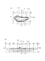
図6は、コンピュータシミュレーションにより作図されたスクリーン上の配光パターンを簡略化して示す等光度曲線の説明図であって、中央の等光度曲線は、高光度帯であって、その他の曲線は、外に行くにしたがって低くなる光度帯である。 FIG. 6 is an explanatory diagram of an isoluminous curve showing the light distribution pattern on the screen drawn by computer simulation in a simplified manner. The central isoluminous curve is a high luminous intensity band, and the other curves are It is a light intensity zone that decreases as you go outside.
(構成の説明)
以下、この実施形態における車両用前照灯の構成について説明する。図1中、符号1L、1Rは、この実施形態における車両用前照灯(たとえば、ヘッドランプなど)である。前記車両用前照灯1L、1Rは、左側通行用の車両Cの前部の左右両端部に搭載されている。以下、車両Cの左側Lに搭載される左側の車両用前照灯1Lについて説明する。なお、車両Cの右側Rに搭載される右側の車両用前照灯1Rは、左側の車両用前照灯1Lとほぼ同様の構成をなすので、説明を省略する。
(Description of configuration)
Hereinafter, the configuration of the vehicle headlamp in this embodiment will be described. In FIG. 1,
(車両用前照灯1Lの説明)
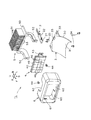
前記車両用前照灯1Lは、図2〜図5に示すように、ランプハウジング(図示せず)と、ランプレンズ(図示せず)と、半導体型光源2と、リフレクタ3と、レンズ4と、ヒートシンク部材5と、カバー部材6と、を備えるものである。
(Description of
2 to 5, the
前記半導体型光源2および前記リフレクタ3および前記レンズ4および前記ヒートシンク部材5および前記カバー部材6は、ランプユニットを構成する。前記ランプハウジングおよび前記ランプレンズは、灯室(図示せず)を画成する。前記ランプユニット2、3、4、5、6は、前記灯室内に配置されていて、かつ、上下方向用光軸調整機構(図示せず)および左右方向用光軸調整機構(図示せず)を介して前記ランプハウジングに取り付けられている。
The semiconductor-
(半導体型光源2の説明)
前記半導体型光源2は、図2、図5に示すように、この例では、たとえば、LED、EL(有機EL)などの自発光半導体型光源である。前記半導体型光源2は、発光チップ(LEDチップ)20と、前記発光チップ20を封止樹脂部材で封止したパッケージ(LEDパッケージ)と、前記パッケージを実装した基板21と、前記基板21に取り付けられていて前記発光チップ20に電源(バッテリー)からの電流を供給するコネクタ22と、から構成されている。前記基板21は、スクリュー23により、前記ヒートシンク部材5に固定されている。この結果、前記半導体型光源2は、前記ヒートシンク部材5に固定されている。
(Description of the semiconductor-type light source 2)
As shown in FIGS. 2 and 5, the semiconductor-
前記発光チップ20は、平面矩形形状(平面長方形状)をなす。すなわち、複数個たとえば4個の正方形のチップをX軸方向(左右の水平方向)に配列してなるものである。なお、1個の長方形のチップ、あるいは、1個の正方形のチップ、を使用しても良い。前記発光チップ20の長方形の下側Dの面(下面)は、発光面24をなす。この結果、前記発光面24は、下側Dに向いている。前記発光チップ20の前記発光面24の中心Oは、前記リフレクタ3の基準焦点F1もしくはその近傍に位置し、かつ、前記リフレクタ3の基準光軸(基準軸)Z上もしくはその近傍に位置する。
The
図4、図5において、X、Y、Zは、直交座標(X−Y−Z直交座標系)を構成する。前記X軸は、前記発光チップ20の前記発光面24の中心Oを通る左右方向の水平軸である。前記X軸は、車両Cの内側、すなわち、この実施形態において、右側Rが+方向であり、車両Cの外側、すなわち、この実施形態において、左側Lが−方向である。また、前記Y軸は、前記発光チップ20の前記発光面24の中心Oを通る上下方向の鉛直軸(垂直軸、法線、垂線)である。前記Y軸は、この実施形態において、上側Uが+方向であり、下側Dが−方向である。さらに、前記Z軸は、前記リフレクタ3の基準光軸Zであり、前記発光チップ20の前記発光面24の中心Oを通り、かつ、前記X軸および前記Y軸と直交する前後方向の軸である。前記Z軸は、この実施形態において、前側Fが+方向であり、後側Bが−方向である。
4 and 5, X, Y, and Z constitute an orthogonal coordinate (XYZ orthogonal coordinate system). The X axis is a horizontal axis in the horizontal direction passing through the center O of the
(リフレクタ3の説明)
前記リフレクタ3は、図2に示すように、反射部30と、取付部33と、から構成されている。前記取付部33は、スクリュー34により、前記ヒートシンク部材5に固定されている。この結果、前記リフレクタ3は、前記ヒートシンク部材5に固定されている。
(Description of reflector 3)
As shown in FIG. 2, the
前記反射部30の前側Fの面(内面)には、ひとつの連続面で形成された反射面31が設けられている。前記反射面31は、パラボラ系の自由曲面からなる反射面である。この結果、前記反射面31(前記リフレクタ3)は、前記基準焦点F1および前記基準光軸Zを有する。
A
前記反射面31は、前記半導体型光源2の前記発光面24からの光を、図6(A)に示す、斜めカットオフラインCL1と水平カットオフラインCL2とエルボー点E(斜めカットオフラインCL1と水平カットオフラインCL2との交点もしくはその近傍の点)とを有する基本配光パターンPとして反射させる自由曲面の反射面である。ここで、前記基本配光パターンPにおいて、スクリーンの左右の水平線HL−HRの左側約5°から約10°前後にかけての部分には、光の抜けを防止して、滑らかな配光パターンが形成されている。
The
前記反射面31は、蒸着により形成されている。前記蒸着の構造は、まず、前記リフレクタ3の母材の表面に密着性を高めるためのアンダーコート層が形成され、つぎに、前記アンダーコート層の上に反射層のアルミ蒸着層が形成され、さらに、前記アルミ蒸着層の上に耐候性を高めるためのトップコート層が形成されてなる構造である。前記蒸着時において、前記リフレクタ3の前記反射面31下端部には、蒸着溜り36(図5中の点線で示される箇所を参照)が形成される。
The
(補助反射面35の説明)
前記リフレクタ3の上縁の中央部すなわち前記ヒートシンク部材5のシェード部53に対応する部分には、補助反射面35が設けられている。前記補助反射面35は、前記半導体型光源2からの光の一部(図示せず)を前記ヒートシンク部材5のシェード部53を交わすように反射させるものである。前記ヒートシンク部材5のシェード部53を交わした反射光(図示せず)は、前記レンズ4を透過して車両Cの前方(前側F)に所定の配光パターン(図示せず)で照射され、もしくは、前記カバー部材6に設けた窓部(図示せず)を通過して車両Cの外側に所定の配光パターン(図示せず)で照射される。
(Description of auxiliary reflecting surface 35)
An
(レンズ4の説明)
前記レンズ4は、図2〜図5に示すように、正面視長方形形状をなすレンズ部40と、前記レンズ部40の周囲に一体に設けられている係合部49と、前記係合部49の左右両側に一体に設けられている取付部43と、から構成されている。前記係合部49は、前記レンズ部40よりも後側Bに一段下がっている。前記係合部49のうち少なくとも入射面(全反射面を含む場合がある)には、シボなどの拡散面もしくは遮光面(図示せず)が設けられている。前記取付部43は、スクリュー44により、前記ヒートシンク部材5に固定されている。この結果、前記レンズ4は、前記ヒートシンク部材5に固定されている。前記レンズ4と前記リフレクタ3との間の前後方向の距離は、小さい。
(Description of lens 4)
As shown in FIGS. 2 to 5, the
前記レンズ部40は、複数の凸面を有するレンズ(薄肉レンズ、プリズムレンズ)である。前記レンズ4の前記レンズ部40は、車両Cの平面視において、車両Cの内側(右側R)から外側(左側L)にかけて車両Cの前側Fから後側Bに傾斜(スラント)していて、かつ、車両Cの正面視において、車両Cの内側(右側R)から外側(左側L)にかけて車両Cの下側Dから上側Uに傾斜(スラント)している(つり上がっている)。
The
前記レンズ部40の内面(後側Bの面)には、入射面45が設けられている。前記レンズ4の前記レンズ部40の外面(前側Fの面)には、出射面46が設けられている。前記入射面45は、平面もしくは複合2次曲面をなす。前記出射面46は、複数の前記凸面であって、凸状自由曲面をなす。この結果、前記レンズ4の前記レンズ部40は、軸が上下方向のシリンドリカル状のレンズ部(プリズムレンズ部)をなす。
An
前記レンズ部40は、前記反射面31からの前記基本配光パターンPを、図6(B)に示すように、斜めカットオフラインCL1と水平カットオフラインCL2とエルボー点Eとを有するロービーム用配光パターンLPとして車両の前方に照射する。
The
前記レンズ部40のうち下側Dの部分であって中央の部分(図4中の太い実線で囲まれた範囲の部分)は、低拡散部47である。前記低拡散部47は、前記基本配光パターンPの前記エルボー点Eおよびその近傍の部分であるスポット配光を、前記ロービーム用配光パターンLPのうちの前記エルボー点Eおよびその近傍の部分であるスポット配光として照射する箇所である。すなわち、前記低拡散部47は、前記基本配光パターンPの前記エルボー点Eおよびその近傍を低拡散させて、前記ロービーム用配光パターンLPのうち前記エルボー点Eおよびその近傍を形成するものである。前記低拡散部47の前記凸面(前記出射面46)は、曲率半径が大きい凸面をなす。なお、前記低拡散部47の前記凸面(前記出射面46)の一部は、平面をなす場合がある。この場合、前記基本配光パターンPの前記エルボー点Eおよびその近傍の一部をそのまま透過させる場合がある。
The lower D part of the
前記低拡散部47以外のその他の部分(図4中の太い実線で囲まれた範囲の外側の部分)の前記凸面(前記出射面46)の大部分は、曲率半径が前記低拡散部47の曲率半径よりも小さい凸面をなす。なお、その他の部分のうち、前記低拡散部47と隣接する部分の前記凸面(前記出射面46)は、平面もしくは曲率半径が大きい凸面をなす場合がある。
Most of the convex surface (the exit surface 46) of the other part (the part outside the range surrounded by the thick solid line in FIG. 4) other than the
(反射面31の下端部38とレンズ部40の下端部48との相対位置関係の説明)
図5に示すように、前記反射面31の下端部38のうち少なくとも一部が前記レンズ部40の前記下端部48よりも下側Dに位置する。前記レンズ部40の前記下端部48よりも下側Dに位置する前記反射面31の前記下端部38は、前記レンズ部40のうち前記低拡散部47に対応する箇所である。なお、前記反射面31の下端部38の全部が前記レンズ部40の下端部48よりも下側Dに位置していても良い。
(Description of relative positional relationship between the
As shown in FIG. 5, at least a part of the
(ヒートシンク部材5の説明)
前記ヒートシンク部材5は、図2〜図5に示すように、水平板部50と、フィン部51と、取付部52と、前記シェード部53と、から構成されている。前記水平板部50の一面(下側Dの面)には、前記半導体型光源2および前記リフレクタ3が前記スクリュー23、34により取り付けられている。
(Description of heat sink member 5)
As shown in FIGS. 2 to 5, the
前記水平板部50の他面(上側Uの面)には、複数枚の垂直板形状の前記フィン部51が一体に設けられている。前記フィン部51は、前記半導体型光源2の前記発光チップ20で発生する熱を外部に放出するものである。
On the other surface (upper U surface) of the
前記水平板部50の一面の前側Fの縁の左右両端部には、湾曲腕形状の前記取付部52が一体に設けられている。前記取付部52には、前記レンズ4が前記スクリュー44により取り付けられている。
The curved arm-shaped
前記水平板部50の一面の前側Fの縁の中央部には、湾曲形状の前記シェード部53が一体に設けられている。前記シェード部53は、前記半導体型光源2の前記発光面24からの光が前記レンズ4の前記レンズ部40に直接入射するのを防ぐものである。
The
(カバー部材6の説明)
前記カバー部材6は、図2〜図5に示すように、前側Fの部分が閉塞し、かつ、後側Bの部分が開口した中空状のカバー形状をなす。前記カバー部材6は、光不透過性部材から構成されている。
(Description of cover member 6)
As shown in FIGS. 2 to 5, the
前記カバー部材6の前側Fの部分には、長方形形状をなす挿入開口部60が設けられている。前記挿入開口部60には、前記レンズ4の前記レンズ部40が挿入されていて、前記挿入開口部60の縁には、前記レンズ4の前記係合部49が係合されている。前記カバー部材6の前側Fの部分の前記挿入開口部60の内側の左右両側の縁には、取付部61が一体に設けられている。前記取付部61は、前記レンズ4の前記取付部43に取り付けられている。この結果、前記カバー部材6は、前記レンズ4を介して前記ヒートシンク部材5に固定されている。前記カバー部材6の後側Bの開口部の上下の縁の中央部には、通気開口部62が設けられている。
An
前記カバー部材6の前記挿入開口部60の下側Dの縁部は、前記レンズ部40の前記下端部48よりも下側Dに位置する前記反射面31の前記下端部38の前記蒸着溜り36からの反射光を遮蔽する遮蔽部63である。
An edge of the lower side D of the
(作用の説明)
この実施形態における車両用前照灯1L、1Rは、以上のごとき構成からなり、以下、その作用について説明する。
(Description of action)
The vehicle headlamps 1L and 1R in this embodiment are configured as described above, and the operation thereof will be described below.
半導体型光源2の発光チップ20を点灯する。すると、発光チップ20の発光面24から放射される光の大部分は、リフレクタ3の反射面31でレンズ4側に反射される。
The
第1反射面31で反射された反射光は、図6(A)に示すように、斜めカットオフラインCL1と水平カットオフラインCL2とエルボー点Eとを有する基本配光パターンPに配光制御されて、レンズ4のレンズ部40を、入射面45から出射面46へと、透過する。レンズ部40から出射する出射光は、図6(B)に示すように、斜めカットオフラインCL1と水平カットオフラインCL2とエルボー点Eとを有するロービーム用配光パターンLPに配光制御されて車両Cの前方に照射される。
The reflected light reflected by the first reflecting
このとき、発光チップ20の発光面24からの光が反射面31の下端部38の蒸着溜り36に入射すると、配光制御されていない反射光(図5中の破線矢印を参照)として蒸着溜り36から反射される。配光制御されていない反射光は、下端部48が反射面31の下端部38よりも上側Uに位置するレンズ部40を透過するのを妨げられる。また、配光制御されていない反射光は、遮蔽部63により遮蔽される。これにより、配光制御されていない反射光がレンズ部40を透過して迷光が発生するのを防ぐことができ、良好なロービーム用配光パターンLPが得られる。
At this time, when light from the
ここで、レンズ部40の周囲に一体に設けられている係合部49のうち少なくとも入射面(全反射面を含む場合がある)には、シボなどの拡散面もしくは遮光面が設けられている。このために、反射光が係合部49に入射したとしても、その反射光が全反射して迷光となるのを防ぐことができる。
Here, among the engaging
(効果の説明)
この実施形態における車両用前照灯1L、1Rは、以上のごとき構成および作用からなり、以下、その効果について説明する。
(Explanation of effect)
The vehicle headlamps 1L and 1R in this embodiment are configured and operated as described above, and the effects thereof will be described below.
この実施形態における車両用前照灯1L、1Rは、良好なロービーム用配光パターンLPを得ることができる。 The vehicle headlamps 1L and 1R in this embodiment can obtain a good low beam light distribution pattern LP.
すなわち、この実施形態における車両用前照灯1L、1Rは、反射面31の下端部38のうち少なくとも一部がレンズ部40の下端部48よりも下側Dに位置する。この結果、配光制御されていない蒸着溜り36からの反射光が、下端部48が反射面31の下端部38よりも上側Uに位置するレンズ部40を透過するのを防ぐことができる。これにより、配光制御されていない反射光がレンズ40を透過して迷光が発生するのを防ぐことができ、良好なロービーム用配光パターンLPが得られる。
That is, in the
この実施形態における車両用前照灯1L、1Rは、レンズ部40の下端部48よりも下側Dに位置する反射面31の下端部38が、レンズ部40のうち基本配光パターンPを左右方向に低拡散させる低拡散部47に対応する箇所である。この低拡散部47は、配光制御されていない蒸着溜り36からの反射光を左右方向に低拡散させて外部に照射するので、迷光の影響が大きい。ところが、この実施形態における車両用前照灯1L、1Rは、反射面31の下端部38が低拡散部47よりも下側に位置する。この結果、配光制御されていない蒸着溜り36からの反射光が、下端部48が反射面31の下端部38よりも上側Uに位置するレンズ部40の低拡散部47を透過するのを防ぐことができる。これにより、配光制御されていない反射光がレンズ40を透過して影響が大きい迷光の発生を防ぐことができ、良好なロービーム用配光パターンLPが得られる。
In the
この実施形態における車両用前照灯1L、1Rは、レンズ部40の下端部48よりも下側Dに位置する反射面31の下端部38の蒸着溜り36からの反射光を遮蔽する光不透過性部材すなわちカバー部材6の遮蔽部63を備える。この結果、配光制御されていない蒸着溜り36からの反射光が遮蔽部63により遮蔽される。これにより、配光制御されていない反射光がレンズ部40を透過して迷光が発生するのを防ぐことができ、良好なロービーム用配光パターンLPが得られる。
The
この実施形態における車両用前照灯1L、1Rは、リフレクタ3を代えずに、レンズ4を代えた(取り替えた)場合においても、配光制御されていない蒸着溜り36からの反射光がレンズ部40を透過するのを防ぐことができる。これにより、リフレクタ3をそのままで、レンズ4を様々な形状(たとえば、車両Cの内側から外側にかけて下側Dから上側Uにつり上がった形状、あるいは、車両Cの内側から外側にかけて上側Uから下側Dに垂れ下がった形状)に代える(取り替える)ことが可能である。
In the vehicle headlamps 1L and 1R in this embodiment, even when the
この実施形態における車両用前照灯1L、1Rは、レンズ部40の周囲にはカバー部材6に係合する係合部49が設けられていて、その係合部49のうち少なくとも入射面(全反射面を含む場合がある)にはシボなどの拡散面もしくは遮光面が設けられている。このために、反射光が係合部49に入射したとしても、その反射光が全反射して迷光となるのを防ぐことができる。特に、図5に示すように、レンズ部40の下端部48の係合部49に配光制御されていない反射光が入射したとしても、その反射光が全反射して迷光となるのを防ぐことができる。
In the vehicle headlamps 1L and 1R in this embodiment, an
この実施形態における車両用前照灯1L、1Rは、レンズ4とリフレクタ3との間の前後方向の距離、すなわち、リフレクタ3の反射面31からレンズ4の入射面45までの距離が小さい。このために、リフレクタ3の反射面31とレンズ4のレンズ部40との間の相対位置のずれが多少あっても、基本配光パターンPからロービーム用配光パターンLPへの配光制御への影響が小さい。すなわち、高精度の配光制御が可能である。
In the vehicle headlamps 1L and 1R in this embodiment, the distance in the front-rear direction between the
(実施形態以外の例の説明)
この実施形態においては、車両Cが左側通行の場合の車両用前照灯1L、1Rについて説明するものである。ところが、この発明においては、車両Cが右側通行の場合の車両用前照灯にも適用することができる。
(Description of example other than embodiment)
In this embodiment, the vehicle headlamps 1L and 1R when the vehicle C is on the left side will be described. However, the present invention can also be applied to a vehicle headlamp when the vehicle C is right-hand traffic.
また、この実施形態においては、カバー部材6の遮蔽部63により配光制御されていない蒸着溜り36からの反射光を遮蔽するものである。ところが、この発明においては、レンズ4の入射面45側あるいは出射面46側に光不透過性部材たとえばインナーパネルを配置した場合、このインナーパネルに遮蔽部を設けても良い。
Further, in this embodiment, the reflected light from the
さらに、この実施形態においては、レンズ4の出射面46が複数の凸面をなすものである。ところが、この発明においては、レンズの入射面が複数の凸面をなすものであっても良いし、レンズの出射面および入射面が複数の凸面をなすものであっても良い。
Furthermore, in this embodiment, the
さらにまた、この実施形態においては、配光パターンとして、斜めカットオフラインCL1と水平カットオフラインCL2とエルボー点Eとを有するロービーム用配光パターンLPについて説明するものである。ところが、この発明においては、配光パターンとして、斜めカットオフラインを有しない配光パターンであっても良い。 Furthermore, in this embodiment, a low beam light distribution pattern LP having an oblique cutoff line CL1, a horizontal cutoff line CL2, and an elbow point E will be described as a light distribution pattern. However, in the present invention, the light distribution pattern may be a light distribution pattern having no oblique cutoff line.
1L 左側の車両用前照灯
1R 右側の車両用前照灯
2 半導体型光源
20 発光チップ
21 基板
22 コネクタ
23 スクリュー
24 発光面
3 リフレクタ
30 反射部
31 反射面
33 取付部
34 スクリュー
35 補助反射面
36 蒸着溜り
38 下端部
4 レンズ
40 レンズ部
43 取付部
44 スクリュー
45 入射面
46 出射面
47 低拡散部
48 下端部
49 係合部
5 ヒートシンク部材
50 水平板部
51 フィン部
52 取付部
53 シェード部
6 カバー部材
60 挿入開口部
61 取付部
62 通気開口部
63 遮蔽部
F 前側
B 後側
U 上側
D 下側
L 左側(車両外側)
R 右側(車両内側)
C 車両
CL1 斜めカットオフライン
CL2 水平カットオフライン
E エルボー点
F1 リフレクタの基準焦点
HL−HR スクリーンの左右の水平線
VU−VD スクリーンの上下の垂直線
LP ロービーム用配光パターン
O 発光面の中心
P 基本配光パターン
X X軸
Y Y軸
Z リフレクタの基準光軸(Z軸)
1L
R right side (vehicle inside)
C Vehicle CL1 Oblique cut-off line CL2 Horizontal cut-off line E Elbow point F1 Reflector reference focal point HL-HR Horizontal horizontal line on the screen VU-VD Vertical line on the screen LP Low beam light distribution pattern O Center of light emitting surface P Basic light distribution Pattern X X-axis Y Y-axis Z Reflector reference optical axis (Z-axis)
Claims (4)
前記半導体型光源は、下向きの発光面を有し、
前記リフレクタは、前記半導体型光源の前記発光面からの光をカットオフラインを有する基本配光パターンとして反射させる反射面を有し、
前記レンズは、複数の凸面を有し、前記反射面からの前記基本配光パターンをカットオフラインを有する配光パターンとして車両の前方に照射するレンズ部を有し、
前記反射面は、蒸着により形成されていて、
前記反射面の下端部のうち少なくとも一部が前記レンズ部の下端部よりも下側に位置する、
ことを特徴とする車両用前照灯。 A semiconductor-type light source, a reflector, and a lens;
The semiconductor-type light source has a downward light emitting surface,
The reflector has a reflecting surface that reflects light from the light emitting surface of the semiconductor light source as a basic light distribution pattern having a cut-off line;
The lens has a plurality of convex surfaces, and has a lens portion that irradiates the front of the vehicle as a light distribution pattern having a cut-off line with the basic light distribution pattern from the reflection surface,
The reflective surface is formed by vapor deposition,
At least a part of the lower end portion of the reflecting surface is located below the lower end portion of the lens portion,
A vehicle headlamp characterized by that.
ことを特徴とする請求項1に記載の車両用前照灯。 The lower end portion of the reflecting surface located below the lower end portion of the lens portion is a spot that irradiates spot light distribution in the basic light distribution pattern in the lens portion.
The vehicle headlamp according to claim 1.
ことを特徴とする請求項1または2に記載の車両用前照灯。 A light-impermeable member that shields reflected light from the lower end of the reflecting surface located below the lower end of the lens unit;
The vehicle headlamp according to claim 1 or 2, characterized in that
前記係合部のうち少なくとも入射面には、拡散面もしくは遮光面が設けられている、
ことを特徴とする請求項3に記載の車両用前照灯。 The lens part is provided with an engaging part that engages with the light-impermeable member,
A diffusion surface or a light shielding surface is provided at least on the incident surface of the engaging portion.
The vehicular headlamp according to claim 3.
Priority Applications (5)
| Application Number | Priority Date | Filing Date | Title |
|---|---|---|---|
| JP2012062644A JP2013196902A (en) | 2012-03-19 | 2012-03-19 | Vehicle headlamp |
| KR1020130027906A KR102000535B1 (en) | 2012-03-19 | 2013-03-15 | Headlight for vehicles |
| US13/838,854 US9133999B2 (en) | 2012-03-19 | 2013-03-15 | Vehicle headlamp |
| EP13159927.6A EP2642188B1 (en) | 2012-03-19 | 2013-03-19 | Vehicle headlamp |
| CN201310087034.4A CN103322487B (en) | 2012-03-19 | 2013-03-19 | Headlight for automobile |
Applications Claiming Priority (1)
| Application Number | Priority Date | Filing Date | Title |
|---|---|---|---|
| JP2012062644A JP2013196902A (en) | 2012-03-19 | 2012-03-19 | Vehicle headlamp |
Publications (1)
| Publication Number | Publication Date |
|---|---|
| JP2013196902A true JP2013196902A (en) | 2013-09-30 |
Family
ID=49395608
Family Applications (1)
| Application Number | Title | Priority Date | Filing Date |
|---|---|---|---|
| JP2012062644A Pending JP2013196902A (en) | 2012-03-19 | 2012-03-19 | Vehicle headlamp |
Country Status (1)
| Country | Link |
|---|---|
| JP (1) | JP2013196902A (en) |
Cited By (2)
| Publication number | Priority date | Publication date | Assignee | Title |
|---|---|---|---|---|
| JP2017054690A (en) * | 2015-09-09 | 2017-03-16 | 市光工業株式会社 | Vehicle lighting tool |
| CN112236616A (en) * | 2018-10-25 | 2021-01-15 | 华域视觉科技(上海)有限公司 | Lighting Modules, Lamps and Vehicles |
-
2012
- 2012-03-19 JP JP2012062644A patent/JP2013196902A/en active Pending
Cited By (2)
| Publication number | Priority date | Publication date | Assignee | Title |
|---|---|---|---|---|
| JP2017054690A (en) * | 2015-09-09 | 2017-03-16 | 市光工業株式会社 | Vehicle lighting tool |
| CN112236616A (en) * | 2018-10-25 | 2021-01-15 | 华域视觉科技(上海)有限公司 | Lighting Modules, Lamps and Vehicles |
Similar Documents
| Publication | Publication Date | Title |
|---|---|---|
| US9500334B2 (en) | Vehicle lamp having auxiliary lens with main lens | |
| JP6070105B2 (en) | Vehicle headlamp | |
| KR20130106305A (en) | Headlight for vehicles | |
| CN102213389A (en) | Vehicle headlamp | |
| JP6179070B2 (en) | Vehicle lighting | |
| JP2011171121A (en) | Headlight for vehicle | |
| WO2019230703A1 (en) | Vehicular lamp | |
| JP2013051168A (en) | Headlamp for vehicle | |
| JP5935507B2 (en) | Vehicle headlamp | |
| JP2012089333A (en) | Lamp for vehicle | |
| JP6582524B2 (en) | Vehicle lighting | |
| WO2017135435A1 (en) | Vehicular lighting | |
| JP6171163B2 (en) | Vehicle headlamp | |
| JP6019643B2 (en) | Vehicle headlamp | |
| JP6064439B2 (en) | Vehicle headlamp | |
| JP6003434B2 (en) | Vehicle lighting | |
| JP6244715B2 (en) | Vehicle lighting | |
| JP6056615B2 (en) | Vehicle lighting | |
| JP2017016819A (en) | Vehicular head lamp | |
| JP2013246944A (en) | Vehicle headlight | |
| JP5982986B2 (en) | Vehicle headlamp | |
| JP6056616B2 (en) | Vehicle lighting | |
| JP2013196902A (en) | Vehicle headlamp | |
| JP6471457B2 (en) | Vehicle lighting | |
| WO2014207817A1 (en) | Vehicle headlight |