JP2014201967A - Vehicular door grip - Google Patents

Vehicular door grip Download PDF

Info

Publication number
JP2014201967A
JP2014201967A JP2013079074A JP2013079074A JP2014201967A JP 2014201967 A JP2014201967 A JP 2014201967A JP 2013079074 A JP2013079074 A JP 2013079074A JP 2013079074 A JP2013079074 A JP 2013079074A JP 2014201967 A JP2014201967 A JP 2014201967A
Authority
JP
Japan
Prior art keywords
door
grip
vehicle
automatic
grip portion
Prior art date
Legal status (The legal status is an assumption and is not a legal conclusion. Google has not performed a legal analysis and makes no representation as to the accuracy of the status listed.)
Granted
Application number
JP2013079074A
Other languages
Japanese (ja)
Other versions
JP6010499B2 (en
Inventor
誠雄 関
Masao Seki
誠雄 関
宣夫 福井
Nobuo Fukui
宣夫 福井
宏和 鈴村
Hirokazu Suzumura
宏和 鈴村
祐幸 野村
Yuko Nomura
祐幸 野村
辰弥 清水
Tatsuya Shimizu
辰弥 清水
Current Assignee (The listed assignees may be inaccurate. Google has not performed a legal analysis and makes no representation or warranty as to the accuracy of the list.)
Toyota Motor Corp
Aisin Corp
Original Assignee
Aisin Seiki Co Ltd
Toyota Motor Corp
Priority date (The priority date is an assumption and is not a legal conclusion. Google has not performed a legal analysis and makes no representation as to the accuracy of the date listed.)
Filing date
Publication date
Application filed by Aisin Seiki Co Ltd, Toyota Motor Corp filed Critical Aisin Seiki Co Ltd
Priority to JP2013079074A priority Critical patent/JP6010499B2/en
Publication of JP2014201967A publication Critical patent/JP2014201967A/en
Application granted granted Critical
Publication of JP6010499B2 publication Critical patent/JP6010499B2/en
Active legal-status Critical Current
Anticipated expiration legal-status Critical

Links

Images

Landscapes

  • Lock And Its Accessories (AREA)
  • Passenger Equipment (AREA)

Abstract

【課題】 身体保持の用途のみならず、様々な使用態様に適用可能なドアグリップを提供する。【解決手段】 本発明は、上記課題を解決するために、下記の構成を備える車両用ドアグリップを提供する。すなわち、提供される車両用ドアグリップは、把持部と、把持部の一端をドアの車室内側に支持するヒンジと、把持部の他端を移動方向に移動可能に支え、ドアの車室内側に支持される支持部と、把持部の移動方向において把持部を係止する係止手段とを備える。【選択図】 図3APROBLEM TO BE SOLVED: To provide a door grip applicable not only for body holding but also for various usage modes. In order to solve the above-described problems, the present invention provides a vehicle door grip having the following configuration. That is, the provided vehicle door grip includes a gripping portion, a hinge that supports one end of the gripping portion on the door interior side of the door, and the other end of the gripping portion movably moved in the moving direction. A support portion supported by the holding portion, and locking means for locking the grip portion in the moving direction of the grip portion. [Selection] Figure 3A

Description

本発明は、車両用ドアグリップに関する。   The present invention relates to a vehicle door grip.

従来から、車両のドアに設けられたドアグリップが知られている。ドアグリップは、ユーザによって、車両の走行中に体を支える目的やドアの開閉操作をし易くする目的で用いられている。   Conventionally, a door grip provided on a door of a vehicle is known. The door grip is used by a user for the purpose of supporting the body while the vehicle is traveling and for the purpose of facilitating the opening / closing operation of the door.

ドアグリップに関しては、ドアトリムに設けられた取っ手型の一般的なドアグリップ以外にも、特開平8−156596号公報(特許文献1)に開示されるようなドアグリップ兼用プルハンドルも知られている。当該プルハンドルでは、ドアの開閉操作に用いられるプルハンドルの車室内方向の側面にへこみ部を設けることで、身体保持のためのグリップ機能が達成されている。   As for the door grip, in addition to a handle-type general door grip provided on the door trim, a door grip / pull handle as disclosed in JP-A-8-156596 (Patent Document 1) is also known. . In the pull handle, a grip function for holding the body is achieved by providing a dent portion on the side surface in the vehicle interior direction of the pull handle used for opening and closing the door.

また、特開平9−317323号公報(特許文献2)には、ドアグリップに感圧センサを設けることにより、ユーザの意思に適切に対応する車両ドアの開閉制御を行う車両ドア開閉装置開示されている。すなわち、ドアトリムに設けられた車室内取っ手(ドアグリップ)に感圧センサが設けられており、ユーザによって当該車室内取っ手に加えられる圧力に応じて、ドアの開閉操作を補助するためのドア操作力が生成される。   Japanese Patent Laid-Open No. 9-317323 (Patent Document 2) discloses a vehicle door opening / closing device that performs opening / closing control of a vehicle door appropriately corresponding to the user's intention by providing a pressure sensor on the door grip. Yes. That is, a pressure sensor is provided in a vehicle interior handle (door grip) provided in the door trim, and a door operation force for assisting in opening and closing the door according to the pressure applied to the vehicle interior handle by the user. Is generated.

特開平8−156596号公報JP-A-8-156596 特開平9−317323号公報JP 9-317323 A

上記のように、従来から車両のドアに設けられたドアグリップについては、プルハンドルの形状として構成することや、ドアの開閉操作をよりし易くするための機能を付加した構成にすることなど種々の工夫が知られている。しかしながら、従来のドアグリップは、車両の走行中にユーザの体を支えるという用途に適うため、ドアに対して移動できないように固定されていた。そのため、ドアグリップの使用態様が制限されていた。   As described above, the door grips conventionally provided on the doors of the vehicle are variously configured as a pull handle shape, or a structure added with a function for facilitating the opening / closing operation of the door. The ingenuity is known. However, since the conventional door grip is suitable for the purpose of supporting the user's body while the vehicle is running, it has been fixed so that it cannot move relative to the door. Therefore, the usage mode of the door grip has been limited.

本発明は、身体保持の用途のみならず、様々な使用態様に適用可能なドアグリップを提供することを目的とする。   An object of this invention is to provide the door grip applicable not only to the use of body holding but to various usage modes.

すなわち、本発明は、車両用ドアグリップであって、把持部と、把持部の一端をドアの車室内側に支持するヒンジと、把持部の他端を移動方向に移動可能に支え、前記ドアの車室内側に支持される支持部と、把持部の移動方向において把持部を係止する係止手段とを備える、車両用ドアグリップを提供する。   That is, the present invention is a vehicle door grip, comprising a gripping portion, a hinge that supports one end of the gripping portion on the interior side of the door, and the other end of the gripping portion movably supported in the moving direction. There is provided a vehicle door grip including a support portion supported on the vehicle interior side and a locking means for locking the grip portion in the moving direction of the grip portion.

上記構成により、提供されるドアグリップでは、ドアグリップの把持部がヒンジの回転により移動することができ、把持部は移動方向に存する係止手段によって係止されることができる。そのため、提供されるドアグリップは、所定の空間間隔において可動であり、様々な使用態様に適用可能である。さらに、把持部は係止手段により係止されるため把持部の移動後であっても十分な身体保持機能を果たすことができる。   With the above structure, in the provided door grip, the grip portion of the door grip can be moved by the rotation of the hinge, and the grip portion can be locked by the locking means existing in the moving direction. Therefore, the provided door grip is movable at a predetermined space interval and can be applied to various usage modes. Furthermore, since the grip portion is locked by the locking means, a sufficient body holding function can be achieved even after the grip portion is moved.

本発明のさらなる特徴は、添付図面を参照して例示的に示した以下の実施例の説明から明らかになる。   Further features of the present invention will become apparent from the following description of embodiments, given by way of example with reference to the accompanying drawings.

第1の実施形態によるドアグリップを備えたドアの模式図である。It is a schematic diagram of the door provided with the door grip by 1st Embodiment. 第1の実施形態によるドアグリップの斜視図である。It is a perspective view of the door grip by a 1st embodiment. 第1の実施形態による移動前のドアグリップの上部の断面図である。It is sectional drawing of the upper part of the door grip before the movement by 1st Embodiment. 第1の実施形態によるドアグリップの把持部の移動を示す。The movement of the grip part of the door grip by 1st Embodiment is shown. 第1の実施形態による移動後のドアグリップの上部の断面図である。It is sectional drawing of the upper part of the door grip after the movement by 1st Embodiment. 把持部が解除状態にある、第2の実施形態によるドアグリップの斜視図である。It is a perspective view of the door grip by 2nd Embodiment with a holding part in a cancellation | release state. 第2の実施形態によるドアグリップの固定手段の斜視図である。It is a perspective view of the fixing means of the door grip by 2nd Embodiment. 把持部が解除状態にある、第2の実施形態によるドアグリップの上部の断面図である。It is sectional drawing of the upper part of the door grip by 2nd Embodiment which has a holding part in a cancellation | release state. 第2の実施形態によるドアグリップの固定手段の動作を示す。The operation | movement of the fixing means of the door grip by 2nd Embodiment is shown. 把持部が固定状態にある、第2の実施形態によるドアグリップの斜視図である。It is a perspective view of the door grip by 2nd Embodiment with a holding part in a fixed state. 把持部が固定状態にある、第2の実施形態によるドアグリップの上部の断面図である。It is sectional drawing of the upper part of the door grip by 2nd Embodiment which has a holding part in a fixed state. 第2の実施形態によるアクチュエータ、制御部等のブロック図である。It is a block diagram of an actuator, a control part, etc. by a 2nd embodiment. 第3の実施形態による移動前のドアグリップの上部の概略断面図である。It is a schematic sectional drawing of the upper part of the door grip before the movement by 3rd Embodiment. 第3の実施形態による移動後のドアグリップの上部の概略断面図である。It is a schematic sectional drawing of the upper part of the door grip after the movement by 3rd Embodiment. 第3の実施形態によるアクチュエータ、制御部等のブロック図である。It is a block diagram of an actuator, control part, etc. by a 3rd embodiment. 第4の実施形態によるアクチュエータ、制御部等のブロック図である。It is a block diagram of an actuator, control part, etc. by a 4th embodiment. 第4の実施形態の変形例によるアクチュエータ、制御部等のブロック図である。It is a block diagram of an actuator, a control part, etc. by the modification of a 4th embodiment.

以下、本発明を実施するための例示的な実施例を、図面を参照して詳細に説明する。ただし、以下の実施例で説明する寸法、材料、形状、構成要素の相対的な位置等は任意であり、本発明が適用される装置の構成又は様々な条件に応じて変更できる。また、図面において、同一であるか又は機能的に類似している要素を示すために図面間で同じ参照符号を用いる。なお、本明細書において、上下とは重力方向における上方向と下方向とにそれぞれ対応する。   Hereinafter, exemplary embodiments for carrying out the present invention will be described in detail with reference to the drawings. However, dimensions, materials, shapes, relative positions of components, and the like described in the following embodiments are arbitrary and can be changed according to the configuration of the apparatus to which the present invention is applied or various conditions. Also, in the drawings, the same reference numerals are used between the drawings to indicate the same or functionally similar elements. In the present specification, “up and down” corresponds to an upward direction and a downward direction in the direction of gravity, respectively.

[第1の実施形態]
図1は、第1の実施形態によるドアグリップ200が設けられた左側フロントドアDを示す。フロントドアDは、車室外側に位置するアウタパネル(不図示)と、車室内側に位置するインナパネルPと、インナパネルPに取り付けられる内装部材であるドアトリム10とを備える。図1において、ドアグリップ200はドアトリム10の上面張出部11とアームレスト(棚状部)12との間に設けられており、車室内方向に移動することができるように構成されている。ユーザはドアグリップ200を把持することで、車両の走行時などに自身の体を支えることができ、また、乗降車の際に当該ドアグリップ200を用いてドアの開閉操作を容易に行うこともできる。
[First Embodiment]
FIG. 1 shows a left front door D provided with a door grip 200 according to the first embodiment. The front door D includes an outer panel (not shown) located outside the vehicle compartment, an inner panel P located on the vehicle interior side, and a door trim 10 that is an interior member attached to the inner panel P. In FIG. 1, a door grip 200 is provided between an upper surface projecting portion 11 and an armrest (shelf-shaped portion) 12 of the door trim 10, and is configured to be movable in the vehicle interior direction. The user can hold his / her body by gripping the door grip 200 and can easily open and close the door using the door grip 200 when getting on and off the vehicle. it can.

なお、図1においては、ドアグリップ200はドアトリム10の上面張出部11とアームレスト12の間に設けられているが、ドアグリップ200の取り付け態様はこれに限定されない。例えば、ドアグリップ200を概ねU字状に形成するなどして、ドアトリム10の車室内方向の面に設けられてもよい。また、図1は左側フロントドアのドアトリム10を示しているが、ドアグリップ200を右側フロントドアやリアドアなど他のドアにも同様に設けることもできる。   In FIG. 1, the door grip 200 is provided between the upper surface overhanging portion 11 of the door trim 10 and the armrest 12, but the manner of attaching the door grip 200 is not limited to this. For example, the door grip 200 may be provided on the surface of the door trim 10 in the vehicle interior direction, for example, by forming it in a generally U shape. Although FIG. 1 shows the door trim 10 of the left front door, the door grip 200 can be similarly provided to other doors such as the right front door and the rear door.

図2Aは、第1の実施形態によるドアグリップ200を示している。図2A中、方向xは車室内方向を示し、方向yは車両の進行方向を示し、方向zは高さ方向を示しており、これら方向は以下において共通して用いられる。本実施形態によるドアグリップ200は、ユーザによって把持される把持部21と、把持部21の下部(一端)をドアDの車室内側に支持するヒンジ22と、把持部21の上部(他端)を支持するとともにドアDの車室内側に支持されるドアグリップ支持部24を備えている。ヒンジ22はピン15を備え、ピン15は車両の進行方向yを向き水平方向に略平行となるようにインナパネルPに支持されている。これにより、ヒンジ22はピン15を中心軸として回動可能となる。さらにドアグリップ支持部24は、把持部21が移動する移動方向(車室内方向x)において把持部21を係止する係止手段であるブラケット23を有し、ブラケット23はガイド部25を有している。ガイド部25はヒンジ22のピン15が向く方向に対して略垂直な方向に延在している。また、ガイド部25はドアトリム10を介してインナパネルPに固定されている。   FIG. 2A shows a door grip 200 according to the first embodiment. In FIG. 2A, the direction x indicates the vehicle interior direction, the direction y indicates the traveling direction of the vehicle, the direction z indicates the height direction, and these directions are used in common below. The door grip 200 according to the present embodiment includes a grip 21 that is gripped by a user, a hinge 22 that supports a lower portion (one end) of the grip 21 on the vehicle interior side of the door D, and an upper portion (the other end) of the grip 21. And a door grip support portion 24 supported on the vehicle interior side of the door D. The hinge 22 includes a pin 15, and the pin 15 is supported by the inner panel P so as to face the traveling direction y of the vehicle and be substantially parallel to the horizontal direction. As a result, the hinge 22 can be rotated about the pin 15 as a central axis. Furthermore, the door grip support portion 24 has a bracket 23 that is a locking means for locking the grip portion 21 in the moving direction (vehicle interior direction x) in which the grip portion 21 moves. The bracket 23 has a guide portion 25. ing. The guide portion 25 extends in a direction substantially perpendicular to the direction in which the pin 15 of the hinge 22 faces. The guide portion 25 is fixed to the inner panel P via the door trim 10.

図2Bは、ドアグリップ200の上部の概略断面図である。上述したように、ドアグリップ支持部24はドアトリム10を介してインナパネルPに固定されている。把持部21の上部には貫通孔が形成されており、この貫通孔には円柱状のガイド部25が挿入されている。ガイド部25の一端はブラケット23に固定され、ガイド部25の他端はドアトリム10を介してインナパネルPに固定されている。このような構成により、把持部21の上部がガイド部25に沿って車室内方向x(移動方向)に移動可能となる。   FIG. 2B is a schematic cross-sectional view of the upper portion of the door grip 200. As described above, the door grip support 24 is fixed to the inner panel P via the door trim 10. A through hole is formed in the upper portion of the gripping portion 21, and a cylindrical guide portion 25 is inserted into the through hole. One end of the guide portion 25 is fixed to the bracket 23, and the other end of the guide portion 25 is fixed to the inner panel P via the door trim 10. With such a configuration, the upper portion of the grip portion 21 can move in the vehicle interior direction x (movement direction) along the guide portion 25.

図2Cは、把持部21の移動を示す図である。図2Cにおいて、移動前の把持部21を実線で示し、移動後の把持部21を二点鎖線で示している。図2Dは、把持部21が移動した後のドアグリップ200の上部の概略断面図である。   FIG. 2C is a diagram illustrating movement of the grip portion 21. In FIG. 2C, the grip part 21 before movement is indicated by a solid line, and the grip part 21 after movement is indicated by a two-dot chain line. FIG. 2D is a schematic cross-sectional view of the upper portion of the door grip 200 after the grip portion 21 has moved.

ユーザが把持部21を矢印17で示す方向(車室内方向x)に引くと、図2Cに示すように、ヒンジ22がピン15を中心として矢印16で示す方向に回転する。すなわち、把持部21がピン15を中心として矢印17で示す方向(車室内方向x)に向かって回転する。図2Dに示されたように、把持部21が車室内方向xに向かって移動すると、ブラケット23の当接部27が、把持部21の当接部26と当接し、把持部21を係止する。そのため、ドアグリップ200は把持部21の移動後であっても十分な身体保持機能を果たすことができる。なお、ピン15が向く方向及びブラケット23のガイド部25が延在する方向は互いに対応する方向であれば任意の方向とすることができ、そのため把持部21の移動方向も任意とすることができることが理解される。   When the user pulls the grip portion 21 in the direction indicated by the arrow 17 (vehicle interior direction x), the hinge 22 rotates about the pin 15 in the direction indicated by the arrow 16 as shown in FIG. 2C. That is, the gripping part 21 rotates around the pin 15 in the direction indicated by the arrow 17 (vehicle interior direction x). As shown in FIG. 2D, when the grip portion 21 moves in the vehicle interior direction x, the contact portion 27 of the bracket 23 contacts the contact portion 26 of the grip portion 21 to lock the grip portion 21. To do. Therefore, the door grip 200 can perform a sufficient body holding function even after the grip portion 21 is moved. The direction in which the pin 15 faces and the direction in which the guide portion 25 of the bracket 23 extends can be any direction as long as they correspond to each other, and therefore the movement direction of the gripping portion 21 can also be arbitrary. Is understood.

本実施形態によるドアグリップ200では、把持部21の下部がヒンジ22に結合され、上部がドアグリップ支持部24によって支持されている。ドアグリップ支持部24は、把持部21がブラケット23の方向に移動できるように把持部21の上部を支持している。したがって、ドアグリップ200では、把持部21がドアグリップ支持部24のブラケット23に向かって移動することができ、且つ、把持部21の移動方向においてブラケット23が把持部21を係止することができる。そのため、ユーザが把持部21を手動で移動方向に移動させた後であっても、把持部21はブラケット23によって係止されるため、ドアグリップ200は十分な身体保持機能を果たすことができる。   In the door grip 200 according to the present embodiment, the lower portion of the grip portion 21 is coupled to the hinge 22 and the upper portion is supported by the door grip support portion 24. The door grip support part 24 supports the upper part of the grip part 21 so that the grip part 21 can move in the direction of the bracket 23. Therefore, in the door grip 200, the grip portion 21 can move toward the bracket 23 of the door grip support portion 24, and the bracket 23 can lock the grip portion 21 in the moving direction of the grip portion 21. . Therefore, even after the user manually moves the gripping portion 21 in the moving direction, the gripping portion 21 is locked by the bracket 23, so that the door grip 200 can perform a sufficient body holding function.

なお、本実施形態によるドアグリップ200では、把持部21の下部がヒンジ22によってドアトリム10を介してインナパネルPに支持され、上部がドアグリップ支持部24によって支持されるが、それぞれ逆の構成要素によって支持されてもよい。すなわち、把持部21の下部がドアグリップ支持部24によって支持され、上部がヒンジ22によってドアトリム10を介してインナパネルPに支持されるように、ドアグリップ200を構成してもよい。また、ドアグリップ200は、ドアDの車室内側に支持される構成であれば任意の構成によって支持されることができる。例えば、ドアグリップ200は、ドアトリム10を介さずにインナパネルPに直接支持される構成でもよい。すなわち、ドアグリップ200の上部及び下部がインナパネルPに直接支持されていてもよいし、上部及び下部のいずれか一方がドアトリム10を介してインナパネルにPに支持され、他方がインナパネルPに直接支持されていてもよい。また、ドアグリップ200がアームレスト12に支持される構成としてもよい。   In the door grip 200 according to the present embodiment, the lower portion of the grip portion 21 is supported by the inner panel P via the door trim 10 by the hinge 22, and the upper portion is supported by the door grip support portion 24. It may be supported by. That is, the door grip 200 may be configured such that the lower portion of the grip portion 21 is supported by the door grip support portion 24 and the upper portion is supported by the inner panel P via the door trim 10 by the hinge 22. Further, the door grip 200 can be supported by any configuration as long as the door grip 200 is supported on the vehicle interior side of the door D. For example, the door grip 200 may be configured to be directly supported by the inner panel P without using the door trim 10. That is, the upper and lower portions of the door grip 200 may be directly supported by the inner panel P, or one of the upper and lower portions is supported by the inner panel P via the door trim 10 and the other is supported by the inner panel P. It may be supported directly. Further, the door grip 200 may be supported by the armrest 12.

[第2の実施形態]
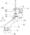
図3A乃至Dを参照して第2の実施形態によるドアグリップ300について説明する。図3Aは第2の実施形態によるドアグリップ300を示す。ここで、把持部21等の構造及び動きについては、第1の実施形態とほぼ同様であるため、相違点を中心に説明する。第2の実施形態によるドアグリップ300は、把持部21を固定するための固定手段30をさらに備えており、固定手段30はアクチュエータ31、並びにレバー32及びシャフト33(移動手段)を有する(図3B)。シャフト33はレバー32に結合されており、レバー32はアクチュエータ31に結合されている。アクチュエータはモータ等によって構成されており、レバー32を回動させることによりシャフト33を上下動させることができる。ドアグリップ300は、把持部21にアクチュエータ31を作動させる作動スイッチ(固定手段作動スイッチ)28を備える。
[Second Embodiment]
A door grip 300 according to a second embodiment will be described with reference to FIGS. 3A to 3D. FIG. 3A shows a door grip 300 according to a second embodiment. Here, since the structure and movement of the gripping portion 21 and the like are substantially the same as those in the first embodiment, the differences will be mainly described. The door grip 300 according to the second embodiment further includes a fixing means 30 for fixing the grip portion 21, and the fixing means 30 includes an actuator 31, a lever 32, and a shaft 33 (moving means) (FIG. 3B). ). The shaft 33 is coupled to the lever 32, and the lever 32 is coupled to the actuator 31. The actuator is constituted by a motor or the like, and the shaft 33 can be moved up and down by rotating the lever 32. The door grip 300 includes an operation switch (fixing means operation switch) 28 that operates the actuator 31 on the grip portion 21.

図3Cは、把持部21、ドアグリップ支持部24、シャフト33等の断面図である。把持部21の上部には開口211が形成され、ドアグリップ支持部24には開口241が形成されている。開口孔211、241はともに円形をなし、両者の径は略同一である。これらの開口211、241の上方にはシャフト33が位置し、シャフト33が開口211、241に挿入することにより、把持部21はドアグリップ支持部24に係止される。   FIG. 3C is a cross-sectional view of the grip portion 21, the door grip support portion 24, the shaft 33, and the like. An opening 211 is formed in the upper part of the grip part 21, and an opening 241 is formed in the door grip support part 24. The opening holes 211 and 241 are both circular and the diameters of both are substantially the same. The shaft 33 is positioned above the openings 211 and 241, and when the shaft 33 is inserted into the openings 211 and 241, the grip portion 21 is locked to the door grip support portion 24.

図4はアクチュエータ31、制御部34等のブロック図である。制御部34はコントローラ、駆動回路等を備える。制御部34には作動スイッチ28、アクチュエータ31、ドアラッチ機構35が接続され、制御部34は、作動スイッチ28及びドアを係止するためのドアラッチ機構35からの信号に基づいて動作するように構成されている。制御部34は、ドアラッチ機構35からドアラッチ(不図示)の係止を示す信号を受け取ると、アクチュエータ31を駆動し、レバー32を下方に移動させる。これにより、後述する固定手段30による固定動作が行われる。これに対し、作動スイッチ28が押されると、制御部34はアクチュエータ31を駆動し、レバー32を上方に移動させる。これにより、後述する固定手段30による解除動作が行われる。なお、アクチュエータ31を作動させる手段は上記手段に限られるものではない。例えば、ドアラッチの係止の解除を禁止するドアロック機構によるドアロック、又は作動スイッチ28あるいはドアトリム10に設けられた作動スイッチ(不図示)の押下に同期して、後述する固定手段30による固定動作を開始させることもできる。また、本実施形態においては、作動スイッチ28は1つのみ設けられているが、複数個設けられてもよい。例えば、後述する固定手段30の固定動作及び解除動作にそれぞれ関連付けられた2つのスイッチを設けてもよい。   FIG. 4 is a block diagram of the actuator 31, the control unit 34, and the like. The control unit 34 includes a controller, a drive circuit, and the like. An operation switch 28, an actuator 31, and a door latch mechanism 35 are connected to the control unit 34, and the control unit 34 is configured to operate based on signals from the operation switch 28 and the door latch mechanism 35 for locking the door. ing. When receiving a signal indicating locking of a door latch (not shown) from the door latch mechanism 35, the controller 34 drives the actuator 31 and moves the lever 32 downward. Thereby, the fixing operation by the fixing means 30 described later is performed. On the other hand, when the operation switch 28 is pressed, the controller 34 drives the actuator 31 and moves the lever 32 upward. Thereby, the releasing operation by the fixing means 30 described later is performed. The means for operating the actuator 31 is not limited to the above means. For example, a fixing operation by a fixing means 30 to be described later in synchronism with a door lock by a door lock mechanism that prohibits unlocking of the door latch, or an operation switch (not shown) provided on the door trim 10. Can also be started. In the present embodiment, only one operation switch 28 is provided, but a plurality of operation switches 28 may be provided. For example, two switches respectively associated with a fixing operation and a releasing operation of the fixing unit 30 to be described later may be provided.

次に、図3A、及びC乃至Fを用いて、固定手段30の動作について説明する。図3Aは把持部21が移動可能な状態(解除状態)にあるときのドアグリップ300を示し、図3Cは把持部21が解除状態にあるときのドアグリップ300の上部の概略断面図である。図3Dは動作中の固定手段30を示し、図3Eは把持部21が固定状態にあるときのドアグリップ300を示し、図3Fは把持部21が固定状態にあるときのドアグリップ300の上部の概略断面図である。なお、図3C及び図3Fでは、説明の簡略化のため、ドアトリム10及びガイド部25が省略されている。   Next, the operation of the fixing means 30 will be described with reference to FIGS. 3A and 3C to 3F. FIG. 3A shows the door grip 300 when the grip portion 21 is in a movable state (release state), and FIG. 3C is a schematic cross-sectional view of the upper portion of the door grip 300 when the grip portion 21 is in the release state. 3D shows the fixing means 30 in operation, FIG. 3E shows the door grip 300 when the grip portion 21 is in a fixed state, and FIG. 3F shows the upper part of the door grip 300 when the grip portion 21 is in a fixed state. It is a schematic sectional drawing. In FIGS. 3C and 3F, the door trim 10 and the guide portion 25 are omitted for simplification of description.

図3A及び図3Cに示す解除状態では、固定手段30のレバー32はアクチュエータ31によって上方に上げられており、レバー32に固定されたシャフト33がドアグリップ支持部24及び把持部21の開口241、211の上方に位置している。そのため、第1の実施形態と同様に、把持部21は車室内方向xに移動することができる。   3A and 3C, the lever 32 of the fixing means 30 is lifted upward by the actuator 31, and the shaft 33 fixed to the lever 32 has the door grip support 24 and the opening 241 of the grip 21. 211 is located above. Therefore, as in the first embodiment, the grip portion 21 can move in the vehicle interior direction x.

把持部21が解除状態にあるときにドアラッチ(不図示)が係止されると、制御部34はアクチュエータ31を駆動し、固定手段30は把持部21を固定する。図3Dはこのときの固定手段30の様子を示しており、把持部21が解除状態にあるときの固定手段30を二点鎖線で示し、把持部21が固定状態にあるときの固定手段30を実線で示している。アクチュエータ31が作動すると、レバー32がアクチュエータ31との結合部を中心として、矢印18で示す方向(下方)に回動する。当該レバー32の回動に伴い、レバー32に結合されているシャフト33が矢印19で示す方向(下方向)に移動し、シャフト33がドアグリップ支持部24に設けられた開口241に挿入される。開口241はドアグリップ支持部24を貫通しているため、開口241を通り抜けたシャフト33は、把持部21の上部に設けられた開口211内に挿入される。なお、この際のレバー32の回動に基づくシャフト33の水平方向の位置ずれを許容するように、開口211、241を当該水平方向においてシャフト33の直径よりも幾分広く構成することができる。   When the door latch (not shown) is locked while the gripping part 21 is in the released state, the control unit 34 drives the actuator 31 and the fixing means 30 fixes the gripping part 21. FIG. 3D shows the state of the fixing means 30 at this time. The fixing means 30 when the grip portion 21 is in the released state is indicated by a two-dot chain line, and the fixing means 30 when the grip portion 21 is in the fixed state is shown. It is shown with a solid line. When the actuator 31 is actuated, the lever 32 pivots in the direction (downward) indicated by the arrow 18 around the coupling portion with the actuator 31. As the lever 32 rotates, the shaft 33 coupled to the lever 32 moves in the direction indicated by the arrow 19 (downward), and the shaft 33 is inserted into the opening 241 provided in the door grip support portion 24. . Since the opening 241 passes through the door grip support portion 24, the shaft 33 passing through the opening 241 is inserted into the opening 211 provided in the upper portion of the grip portion 21. Note that the openings 211 and 241 can be configured to be somewhat wider than the diameter of the shaft 33 in the horizontal direction so as to allow the horizontal displacement of the shaft 33 due to the rotation of the lever 32 at this time.

図3Eは、シャフト33がドアグリップ支持部24及び把持部21に設けられた開口241、211に挿入された状態を示している。このとき、把持部21の開口211内において把持部21の内壁212が、図3Fに示すようにシャフト33によって係止される。そのため、ドアグリップ300は、把持部21が固定された状態(固定状態)となり、把持部21の車室内方向への移動が禁止される。   FIG. 3E shows a state where the shaft 33 is inserted into the openings 241 and 211 provided in the door grip support portion 24 and the grip portion 21. At this time, the inner wall 212 of the gripper 21 is locked by the shaft 33 in the opening 211 of the gripper 21 as shown in FIG. 3F. Therefore, the door grip 300 is in a state where the grip portion 21 is fixed (fixed state), and movement of the grip portion 21 in the vehicle interior direction is prohibited.

把持部21が固定状態にあるときに作動スイッチ28が押下されると、制御部34はアクチュエータ31を駆動し、固定手段30による把持部21の解除動作が開始される。固定手段30による解除動作では、上記固定動作とは逆に、レバー32がアクチュエータ31との結合部を中心として下方から上方へ回動し、レバー32が上方へ回動するのに伴い、シャフト33が各開口211、241から抜き出される。これにより、シャフト33に係止されていた把持部21の内壁212が解放され、把持部21が車室内方向xに移動可能になる。なお、上記のように、作動スイッチ28は把持部21に設けられている。そのため、ユーザは把持部21を手動で移動させる際に、ドアグリップ300から手を放したり持ち替えたりすることなく、ドアグリップ300の把持部21の固定状態を解除することができる。   When the operation switch 28 is pressed while the gripping part 21 is in a fixed state, the control unit 34 drives the actuator 31 and starts the releasing operation of the gripping part 21 by the fixing means 30. In the releasing operation by the fixing means 30, contrary to the above-described fixing operation, the lever 32 rotates from below to above about the coupling portion with the actuator 31, and the shaft 33 rotates as the lever 32 rotates upward. Are extracted from the openings 211 and 241. As a result, the inner wall 212 of the grip portion 21 that is locked to the shaft 33 is released, and the grip portion 21 can move in the vehicle interior direction x. As described above, the operation switch 28 is provided in the grip portion 21. Therefore, when the user manually moves the grip portion 21, the user can release the fixed state of the grip portion 21 of the door grip 300 without releasing the hand from the door grip 300 or changing the hand grip.

なお、本実施形態では、シャフト33の移動方向を上下方向としているが、シャフト33の移動は上下方向に限られず、把持部21及びドアグリップ支持部24の開口211、241の方向に合わせて水平方向(左右方向)等に移動させることもできる。   In the present embodiment, the movement direction of the shaft 33 is the vertical direction. However, the movement of the shaft 33 is not limited to the vertical direction, and the horizontal direction is aligned with the direction of the openings 211 and 241 of the grip portion 21 and door grip support portion 24. It can also be moved in the direction (left-right direction).

本実施形態にしたがったドアグリップ300は、アクチュエータ31、レバー32及びシャフト33を有する固定手段30を備えており、当該固定手段30を作動させることによって、把持部21の移動を禁止するように把持部21を固定することができる。そのため、車両の走行中はドアグリップ300が移動しないように把持部21を固定状態にしておくなどの、よりユーザの意思に沿った操作を可能とするドアグリップ300が提供される。なお、固定手段30に関しては、レバー32及びシャフト33を用いた構成に限られない。例えば、固定手段は回転運動するフック形状のなどの移動部材を備えた構成を有してもよい。また、電磁ブレーキなどの固定手段を用いることもできる。   The door grip 300 according to the present embodiment includes a fixing means 30 having an actuator 31, a lever 32, and a shaft 33. By operating the fixing means 30, gripping is performed so as to prohibit movement of the gripping portion 21. The part 21 can be fixed. For this reason, the door grip 300 is provided that enables an operation more in line with the user's intention, such as keeping the grip portion 21 in a fixed state so that the door grip 300 does not move while the vehicle is traveling. The fixing means 30 is not limited to the configuration using the lever 32 and the shaft 33. For example, the fixing means may have a configuration including a moving member such as a hook shape that rotates. Further, fixing means such as an electromagnetic brake can be used.

[第3の実施形態]
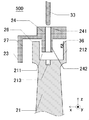
第3の実施形態によるドアグリップ500は、把持部21の移動に基づいて、ドアを係止するドアラッチ(不図示)の係止を解除するように構成されている。ここで、把持部21等の構造及び移動、並びに固定手段30の動作は第2の実施形態とほぼ同様であるため、相違点を中心に説明する。図5A及びBは第3の実施形態によるドアグリップ500の上部の概略断面図である。なお、図5A及びBでは、説明の簡略化のため、ドアトリム10及びガイド部25が省略されている。図5Aを参照すると、第3の実施形態によるドアグリップ500では、ドアグリップ支持部24の下部242が把持部21の開口211内に延在している。また、把持部21の開口211内にシャフト受け凹部213が設けられ、内壁212にラッチ解除スイッチ36がさらに設けられている。シャフト受け凹部213には固定手段30による固定動作が行われる際にシャフト33が挿入され、これにより、把持部21がシャフト33によって係止される。ラッチ解除スイッチ36は、押下されると、ドアを係止するドアラッチ機構35がドアラッチ(不図示)の係止を解除するように構成されている。
[Third Embodiment]
The door grip 500 according to the third embodiment is configured to release the locking of a door latch (not shown) that locks the door based on the movement of the grip portion 21. Here, since the structure and movement of the gripping part 21 and the like and the operation of the fixing means 30 are substantially the same as those in the second embodiment, the description will focus on the differences. 5A and 5B are schematic cross-sectional views of the upper portion of the door grip 500 according to the third embodiment. In FIGS. 5A and 5B, the door trim 10 and the guide portion 25 are omitted for simplification of description. Referring to FIG. 5A, in the door grip 500 according to the third embodiment, the lower portion 242 of the door grip support portion 24 extends into the opening 211 of the grip portion 21. Further, a shaft receiving recess 213 is provided in the opening 211 of the grip portion 21, and a latch release switch 36 is further provided on the inner wall 212. The shaft 33 is inserted into the shaft receiving recess 213 when the fixing operation is performed by the fixing means 30, whereby the grip portion 21 is locked by the shaft 33. When the latch release switch 36 is pressed, the door latch mechanism 35 that locks the door releases the lock of the door latch (not shown).

図6は、第3の実施形態によるドアグリップ500における、アクチュエータ31、制御部34等のブロック図である。第3の実施形態では、制御部34には作動スイッチ28、アクチュエータ31、ドアラッチ機構35及びドアラッチ解除スイッチ36が接続されており、制御部34はドアラッチ解除スイッチ36からの信号にも基づいて動作するように構成されている。ドアラッチ解除スイッチ36が押下されると、制御部34はドアラッチ機構35をドアラッチの係止を解除するように駆動する。このため、ドアラッチ機構35は、ドアラッチ解除スイッチ36の押下に応じてドアラッチの係止を解除する。   FIG. 6 is a block diagram of the actuator 31, the control unit 34, and the like in the door grip 500 according to the third embodiment. In the third embodiment, an operation switch 28, an actuator 31, a door latch mechanism 35, and a door latch release switch 36 are connected to the control unit 34, and the control unit 34 operates based on a signal from the door latch release switch 36. It is configured as follows. When the door latch release switch 36 is pressed, the control unit 34 drives the door latch mechanism 35 so as to release the door latch. Therefore, the door latch mechanism 35 unlocks the door latch in response to the depression of the door latch release switch 36.

第3の実施形態によるドアグリップ500では、ドアグリップ500の把持部21が移動されると、把持部21の開口211内において、延在するドアグリップ支持部の下部242が把持部21の内壁212に設けられたラッチ解除スイッチ36を押下する。この時の様子を図5Bに示す。ラッチ解除スイッチ36が押下されると、上述のようにラッチ機構35がドアラッチの係止を解除する。このため、ユーザは把持部21を移動させることにより、ドアのラッチを解除することができる。ここで、把持部21の開口211はドアグリップ支持部24の延在している下部242の挿入を許容するとともに、該延在している下部242によって把持部21の移動が妨げられない程度の内径を有するように構成されることができる。なお、ラッチの係止を解除する手段は上記手段に限られない。例えば、ドアグリップ500の把持部21にドアラッチ機構に結合されたワイヤ等を結合することなどによっても同様の機能を果たすことができることが理解される。   In the door grip 500 according to the third embodiment, when the grip portion 21 of the door grip 500 is moved, the extended lower portion 242 of the door grip support portion within the opening 211 of the grip portion 21 is the inner wall 212 of the grip portion 21. 1 is pressed. The state at this time is shown in FIG. 5B. When the latch release switch 36 is pressed, the latch mechanism 35 releases the lock of the door latch as described above. For this reason, the user can release the latch of the door by moving the grip portion 21. Here, the opening 211 of the grip portion 21 allows the insertion of the lower portion 242 where the door grip support portion 24 extends, and the movement of the grip portion 21 is not hindered by the extended lower portion 242. It can be configured to have an inner diameter. The means for releasing the latch is not limited to the above means. For example, it is understood that the same function can be achieved by coupling a wire or the like coupled to the door latch mechanism to the grip portion 21 of the door grip 500.

なお、把持部21の移動にドアラッチ解除機能を付加することに伴い、ドアを係止するラッチの係止の解除を禁止するロック機構(不図示)によってドアがロックされたときに、固定手段30による把持部21の固定が維持されるように構成することができる。例えば、ドアがロック状態にあるときに、作動スイッチ28の押下を禁止するために作動スイッチ28を固定するような、電磁ブレーキなどの機構を設けることができる。このような機構を設けることで、車両の走行中などにドアグリップ500の把持部21の移動、すなわちドアのラッチ解除がむやみに生じないようにすることができる。   When the door is unlocked by a lock mechanism (not shown) that prohibits the unlocking of the latch that latches the door in association with the addition of the door latch releasing function to the movement of the gripping portion 21, the fixing means 30 The holding part 21 can be configured to be fixed by the above. For example, a mechanism such as an electromagnetic brake can be provided to fix the operation switch 28 to prohibit the pressing of the operation switch 28 when the door is in a locked state. By providing such a mechanism, it is possible to prevent the movement of the grip portion 21 of the door grip 500, that is, the unlatching of the door from being unnecessarily performed while the vehicle is running.

本実施形態によるドアグリップ500は、把持部21の移動によって、ドアを係止するラッチの係止を解除するように構成される。これにより、従来のドアトリムに設けられていたドアハンドルを省略することができるため、ドアハンドルに使用されていたドアトリム内のスペースを有効に活用できるようになる。また、ドアグリップ500は、把持部21の移動によってドアのラッチを解除できるため、従来のドアのようにドアの開動作時にユーザが手をドアグリップ500から持ち替える必要がなくなるため、ドアの操作性を向上させることもできる。さらに、ドアグリップ500の把持部21の移動方向を車室内方向xとすることにより、従来のドア開動作と同様に車内方向への引く動作によってドアラッチを解除することができ、人の感性に沿った操作ができるようになる。   The door grip 500 according to the present embodiment is configured to unlock the latch that locks the door by the movement of the grip portion 21. Thereby, since the door handle provided in the conventional door trim can be omitted, the space in the door trim used for the door handle can be effectively utilized. Further, since the door grip 500 can release the latch of the door by the movement of the grip portion 21, it is not necessary for the user to change the hand from the door grip 500 when the door is opened unlike the conventional door. Can also be improved. Furthermore, by setting the moving direction of the grip portion 21 of the door grip 500 to the vehicle interior direction x, the door latch can be released by the pulling operation in the vehicle interior direction as in the conventional door opening operation, and in line with human sensitivity. Can be operated.

また、ドアグリップ500は把持部21を固定する固定手段30を備えているため、固定手段30によって把持部21を固定することで、ラッチの係止の解除がむやみに生じないようにすることができる。そのため、ドアグリップ500は、把持部21の移動によってラッチの係止の解除が行える一方で、車両の走行中は固定手段30によって把持部21を固定してラッチの係止の解除を防ぐことができる。さらに、ラッチの係止の解除を禁止するロック機構によってドアがロックされたときに、固定手段30による把持部21の固定を維持するように構成することができる。これにより、把持部の移動が禁止され、ドアラッチの係止の解除を防止することができる。また、把持部21を固定する機構(固定手段30)及び固定手段30による把持部21の固定を維持する機構の双方を採用することにより、車両走行中などドアのラッチが解除されるべきでない場合に二重の機構でドアラッチの係止の解除を防止することができる。   Further, since the door grip 500 includes the fixing means 30 for fixing the grip portion 21, the latch portion 21 is fixed by the fixing means 30 so that the latch is not unnecessarily released. it can. Therefore, the door grip 500 can release the latch by moving the grip 21, while fixing the grip 21 by the fixing means 30 while the vehicle is running to prevent the latch from being released. it can. Furthermore, when the door is locked by a lock mechanism that prohibits the release of the latch, the holding unit 21 can be fixed by the fixing unit 30. Thereby, the movement of the gripping portion is prohibited, and the unlocking of the door latch can be prevented. Further, when both the mechanism (fixing means 30) for fixing the gripping portion 21 and the mechanism for maintaining the fixing of the gripping portion 21 by the fixing means 30 are employed, the door latch should not be released during traveling of the vehicle. Further, it is possible to prevent the door latch from being released by the double mechanism.

[第4の実施形態]
第4の実施形態によるドアグリップは、ドアグリップの把持部21の移動に基づいて、オートドアの開動作を停止するように構成されている。ここで、把持部21等の構造及び移動、並びに固定手段30の動作は第3の実施形態と同様であるため、相違点を中心に説明する。第4の実施形態によるドアグリップでは、第2及び第3の実施形態における作動スイッチ28の代わりにオートドア開動作スイッチ(オートドア作動スイッチ)37を用いる。オートドア開動作スイッチ37は、固定手段30を作動させる機能とドアラッチの係止を解除する機能とを有し、さらに、スイッチ37が押されている間、ドアを自動で開くようにオートドア作動機構38を制御する機能も有している。また、第4の実施形態によるドアグリップでは、第3の実施形態におけるドアラッチ解除スイッチ36に代えて、開口211の内壁212にオートドアの開動作を停止する停止スイッチ39が設けられている。
[Fourth Embodiment]
The door grip according to the fourth embodiment is configured to stop the opening operation of the automatic door based on the movement of the grip portion 21 of the door grip. Here, since the structure and movement of the gripping part 21 and the like and the operation of the fixing means 30 are the same as those in the third embodiment, the description will focus on the differences. In the door grip according to the fourth embodiment, an automatic door opening operation switch (auto door operation switch) 37 is used instead of the operation switch 28 in the second and third embodiments. The automatic door opening operation switch 37 has a function of operating the fixing means 30 and a function of releasing the lock of the door latch, and further, an automatic door operating mechanism 38 so as to automatically open the door while the switch 37 is pressed. It also has a function to control. In the door grip according to the fourth embodiment, a stop switch 39 for stopping the opening operation of the automatic door is provided on the inner wall 212 of the opening 211 in place of the door latch release switch 36 in the third embodiment.

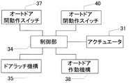
オートドア開動作スイッチ37はアクチュエータ31、並びにドアラッチ機構35及びドアを自動で動作させるオートドア作動機構38に関連付けられている。図7は、第4の実施形態によるドアグリップにおける、アクチュエータ31、制御部34等のブロック図である。第4の実施形態では、制御部34には、アクチュエータ31、ドアラッチ機構35、オートドア開動作スイッチ37、オートドア作動機構38及び停止スイッチ39が接続されている。制御部34は、オートドア開動作スイッチ37、ドアラッチ機構35、停止スイッチ39からの信号に基づいて動作するように構成されている。制御部34がオートドア開動作スイッチ37からの信号を受け取ると、アクチュエータ31、ドアラッチ機構35及びオートドア作動機構38をそれぞれ駆動する。   The automatic door opening operation switch 37 is associated with the actuator 31, the door latch mechanism 35, and the automatic door operation mechanism 38 that automatically operates the door. FIG. 7 is a block diagram of the actuator 31, the control unit 34, and the like in the door grip according to the fourth embodiment. In the fourth embodiment, an actuator 31, a door latch mechanism 35, an automatic door opening operation switch 37, an automatic door operation mechanism 38 and a stop switch 39 are connected to the control unit 34. The control unit 34 is configured to operate based on signals from the automatic door opening operation switch 37, the door latch mechanism 35, and the stop switch 39. When the control unit 34 receives a signal from the automatic door opening operation switch 37, it drives the actuator 31, the door latch mechanism 35, and the automatic door operating mechanism 38, respectively.

これにより、アクチュエータ31は固定手段30による解除動作を開始し、ドアラッチ機構35は、オートドア作動機構38がドアの開動作を開始できるように、ドアラッチの係止を解除する。さらに、ドア内に設けられたオートドア作動機構38は、制御部34がオートドア開動作スイッチ37から信号を受け付けている間、ドアの開動作を行う。これにより、ユーザがオートドア開動作スイッチ37を押下すると、ドアグリップの把持部21が可動となり、ドアラッチの係止が解除され、さらにオートドア開動作スイッチ37が押下されている間、自動でドアの開動作が行われる。ここで、オートドア作動機構38はモータ等によって構成される。オートドア作動機構38は、例えば、ドアと車体とのヒンジ付近に設けられ、スイッチ37が押下されている間モータを稼働させ、その結果生じたドアを操作するためのドア操作力をヒンジに伝えるように構成されることができる。   Thereby, the actuator 31 starts the releasing operation by the fixing means 30, and the door latch mechanism 35 releases the locking of the door latch so that the automatic door operating mechanism 38 can start the door opening operation. Further, the automatic door operation mechanism 38 provided in the door opens the door while the control unit 34 receives a signal from the automatic door opening operation switch 37. As a result, when the user depresses the automatic door opening operation switch 37, the grip portion 21 of the door grip becomes movable, the lock of the door latch is released, and while the automatic door opening operation switch 37 is depressed, the door is automatically opened. Operation is performed. Here, the automatic door operation mechanism 38 is configured by a motor or the like. The automatic door operation mechanism 38 is provided, for example, in the vicinity of the hinge between the door and the vehicle body, operates the motor while the switch 37 is pressed, and transmits the door operation force for operating the resulting door to the hinge. Can be configured.

また、オートドア開動作スイッチ37にドアラッチの係止の解除機能を設けることに伴い、ロック機構によってドアがロック状態にあるときには、オートドア開動作スイッチ37の押下を禁止するように構成することができる。例えば、電磁ブレーキなどの機構を設けることで、ドアがロック状態にあるときに、オートドア開動作スイッチ37の押下を禁止することができ、ドアのラッチ解除がむやみに生じないようにすることができる。   Further, by providing the automatic door opening operation switch 37 with a function of releasing the latching of the door latch, the automatic door opening operation switch 37 can be prohibited from being pressed when the door is locked by the lock mechanism. For example, by providing a mechanism such as an electromagnetic brake, it is possible to prohibit the automatic door opening operation switch 37 from being pressed when the door is in a locked state, and to prevent the door from being unlatched. .

次に、開口211の内壁212に設けられた停止スイッチ39について、再び図7を参照して説明する。停止スイッチ39が押下されると、制御部34はオートドア作動機構38を駆動し、オートドア作動機構38によるドアの開動作を停止させる。ここで、停止スイッチ39は、第3の実施形態においてドアラッチ解除スイッチ36が設けられていた箇所に設けられる。そのため、ユーザが把持部21を移動させると、該移動に伴い把持部21の開口211に延在しているドアグリップ支持部の下部242によって停止スイッチ39が押下され、オートドアの開動作が停止される。   Next, the stop switch 39 provided on the inner wall 212 of the opening 211 will be described again with reference to FIG. When the stop switch 39 is pressed, the control unit 34 drives the automatic door operating mechanism 38 and stops the door opening operation by the automatic door operating mechanism 38. Here, the stop switch 39 is provided at a place where the door latch release switch 36 is provided in the third embodiment. Therefore, when the user moves the gripping part 21, the stop switch 39 is pressed by the lower part 242 of the door grip support part extending to the opening 211 of the gripping part 21 with the movement, and the opening operation of the automatic door is stopped. The

本実施形態にしたがったドアグリップは、ドアを自動で開くためのオートドア作動機構38に関連付けられたオートドア開動作スイッチ37を備え、該スイッチ37はオートドア作動機構38にドアの開動作をさせる機能を有している。そのため、ユーザはオートドア開動作スイッチ37を押している間、オートドア作動機構38を稼働させ、ドアを自動で開かせることができる。また、オートドア開動作スイッチ37は、把持部21の固定状態を解除させる機能及びドアラッチの係止を解除する機能を備えることもできる。これにより、ユーザはドアを開く際に当該オートドア開動作スイッチ37を押下することにより、ドアグリップ500の把持部21を可動にし、ドアのラッチを解除することができる。そのため、ユーザはドアを開く際、従来のドアのようにドアグリップから手を放したり持ち替えたりする必要がないため、ドアの操作性を向上させることができる。また、ドアがロックされたときにオートドア開動作スイッチ37の押下を禁止するように構成することもできる。この場合、車両走行中などドアのラッチが解除されるべきでないときには、ドアをロックすることでオートドア開動作スイッチ37の押下が禁止され、ドアラッチの係止の解除を防止することができる。   The door grip according to the present embodiment includes an automatic door opening operation switch 37 associated with an automatic door operation mechanism 38 for automatically opening the door, and the switch 37 has a function of causing the automatic door operation mechanism 38 to open the door. Have. Therefore, the user can automatically open the door by operating the automatic door operating mechanism 38 while pressing the automatic door opening operation switch 37. Further, the automatic door opening operation switch 37 may have a function of releasing the fixed state of the grip portion 21 and a function of releasing the lock of the door latch. Thus, the user can move the grip portion 21 of the door grip 500 and release the latch of the door by pressing the automatic door opening operation switch 37 when opening the door. Therefore, when the user opens the door, it is not necessary to release the hand from the door grip or to change the position as in the case of a conventional door, so that the operability of the door can be improved. Alternatively, the automatic door opening operation switch 37 can be prohibited from being pressed when the door is locked. In this case, when the door latch should not be released such as when the vehicle is running, the automatic door opening operation switch 37 can be prevented from being pressed by locking the door, and the unlocking of the door latch can be prevented.

また、本実施形態では、第3の実施形態におけるラッチ解除スイッチ36に代えて、停止スイッチ39が把持部21の内壁212に設けられている。停止スイッチ39はオートドア作動機構38によるドアの開動作を停止する機能を有しており、停止スイッチ39が押下されると、オートドア開動作スイッチ37が押されている状態であってもオートドア機構38によるドアの開動作が停止される。そのため、ユーザはドアグリップの把持部21を移動させることにより、停止スイッチ39を押下し、オートドアの開動作を停止させることができる。したがって、ユーザは、ドアの外側に障害物が現れオートドアの開動作を止めようと考えた際などに、オートドア開動作スイッチ37を押したままであっても、把持部21を移動させることで、より直感的にオートドアの開動作を停止させることができる。なお、把持部21の移動方向を車室内方向にすることで、さらに人間の感性に沿った操作ができるようになる。   In the present embodiment, a stop switch 39 is provided on the inner wall 212 of the grip portion 21 instead of the latch release switch 36 in the third embodiment. The stop switch 39 has a function of stopping the opening operation of the door by the automatic door operation mechanism 38. When the stop switch 39 is pressed, the automatic door mechanism 38 is in a state where the automatic door opening operation switch 37 is pressed. The door opening operation by is stopped. Therefore, the user can depress the stop switch 39 by moving the grip portion 21 of the door grip to stop the opening operation of the automatic door. Therefore, when an obstacle appears outside the door and the user thinks that the opening operation of the automatic door is to be stopped, the user can move the grip portion 21 even if the automatic door opening operation switch 37 is held down. The opening operation of the automatic door can be stopped intuitively. It should be noted that the movement direction of the grip portion 21 is set to the vehicle interior direction, so that an operation in accordance with human sensitivity can be performed.

本実施形態では、固定手段30を作動させる機能、ドアラッチの係止を解除する機能及びオートドアを作動させる機能を1つのオートドア開動作スイッチ37に関連付けていたが、複数のスイッチに、例えばそれぞれ別々のスイッチに関連付けることもできる。また、オートドア作動機構は、オートドア開動作スイッチ37が押下されている間だけドアを開く構成に限られず、オートドア開動作スイッチ37が押下されると一度にドアを開ききる構成とすることもできる。さらに、オートドア作動機構38によるドア開動作を停止させる手段は、本実施形態における停止スイッチ37に限られない。例えば、ドアグリップの把持部21にオートドア作動機構に結合されたワイヤを結合することなどによっても同様の機能を果たすことができることが理解される。   In the present embodiment, the function of operating the fixing means 30, the function of releasing the lock of the door latch, and the function of operating the automatic door are associated with one automatic door opening operation switch 37. It can also be associated with a switch. Further, the automatic door operation mechanism is not limited to the configuration in which the door is opened only while the automatic door opening operation switch 37 is pressed, and may be configured to open the door all at once when the automatic door opening operation switch 37 is pressed. Furthermore, the means for stopping the door opening operation by the automatic door operation mechanism 38 is not limited to the stop switch 37 in the present embodiment. For example, it is understood that the same function can be achieved by coupling a wire coupled to the automatic door operation mechanism to the grip portion 21 of the door grip.

また、第4の実施形態の変形例として、停止スイッチ39に代えて、オートドア作動機構38にオートドア閉動作を行わせるオートドア閉動作機能を有するオートドア閉動作スイッチ40を設けることもできる。この場合において、オートドア閉動作スイッチ40も、ドアラッチ解除スイッチ36や停止スイッチ39と同様に、把持部21の内壁212に設けられている。図8は、当該変形例における、アクチュエータ31、制御部34等のブロック図である。当該変形例では、制御部34には停止スイッチ39の代わりに、オートドア閉動作スイッチ40が接続され、制御部34はオートドア閉動作スイッチ40からの信号に基づいて動作することができるように構成されている。オートドア閉動作スイッチ40が押下されると、制御部34はオートドア作動機構38を駆動し、制御部34がオートドア閉動作スイッチ40から信号を受け付けている間、オートドア作動機構38にドアの閉動作を行わせる。これにより、ユーザが把持部21を移動させている間、上述のようにオートドア閉動作スイッチ40が押下されるため、ユーザはドアを自動で閉じさせることができる。また、オートドア閉動作スイッチ40が押下されている間だけドアの閉動作を行う構成に限られず、スイッチ40が押下されるとオートドア作動機構38がドアを一度に閉めきる構成としてもよい。なお、オートドア作動機構38による閉動作を停止するためのスイッチをドアトリム10又はドアグリップに設けることができる。また、例えば、スイッチ40を用いずに、把持部21にオートドア作動機構38に結合されたワイヤを結合することなどによっても同様の機能を果たすことができることが理解される。   As a modification of the fourth embodiment, instead of the stop switch 39, an automatic door closing operation switch 40 having an automatic door closing operation function for causing the automatic door operating mechanism 38 to perform an automatic door closing operation may be provided. In this case, the automatic door closing operation switch 40 is also provided on the inner wall 212 of the grip portion 21, similarly to the door latch release switch 36 and the stop switch 39. FIG. 8 is a block diagram of the actuator 31, the control unit 34, and the like in the modified example. In the modified example, an automatic door closing operation switch 40 is connected to the control unit 34 instead of the stop switch 39, and the control unit 34 is configured to operate based on a signal from the automatic door closing operation switch 40. ing. When the automatic door closing operation switch 40 is pressed, the control unit 34 drives the automatic door operation mechanism 38, and while the control unit 34 receives a signal from the automatic door closing operation switch 40, the automatic door operation mechanism 38 closes the door. Let it be done. Thereby, since the automatic door closing operation switch 40 is pressed as described above while the user moves the grip portion 21, the user can automatically close the door. Further, the present invention is not limited to the configuration in which the door closing operation is performed only while the automatic door closing operation switch 40 is pressed, and the automatic door operating mechanism 38 may be configured to close the door at a time when the switch 40 is pressed. A switch for stopping the closing operation by the automatic door operation mechanism 38 can be provided on the door trim 10 or the door grip. Further, for example, it is understood that the same function can be achieved by coupling a wire coupled to the automatic door operation mechanism 38 to the grip portion 21 without using the switch 40.

以上、実施例を参照して本発明について説明したが、本発明は上記実施例に限定されるものではない。本発明の趣旨に反しない範囲で変更された発明、及び本発明と均等な発明も本発明に含まれる。また、上述の各実施形態及び変形形態は、本発明の趣旨に反しない範囲で適宜組み合わせることができる。   While the present invention has been described with reference to the embodiments, the present invention is not limited to the above embodiments. Inventions modified within the scope not departing from the spirit of the present invention and inventions equivalent to the present invention are also included in the present invention. Moreover, each above-mentioned embodiment and modification can be suitably combined in the range which is not contrary to the meaning of this invention.

10:ドアトリム、11:上面張出部、12:アームレスト、15:ピン、21:把持部、22:ヒンジ、23:ブラケット(係止手段)、24:ドアグリップ支持部(支持部)、25:ガイド部、26当接部、27当接部、28:作動スイッチ(固定手段作動スイッチ)、30:固定手段、31:アクチュエータ、32:レバー、33:シャフト、34:制御部、35:ドアラッチ機構、36:ラッチ解除スイッチ、37:オートドア開動作スイッチ(オートドア作動スイッチ)、38:オートドア作動機構、39:停止スイッチ、40:オートドア閉動作スイッチ、200:ドアグリップ、211:開口、212:内壁、213:シャフト受け凹部、241:開口、242:ドアグリップ支持部の下部、300:ドアグリップ、500:ドアグリップ、D:フロントドア、P:インナパネル 10: Door trim, 11: Overhang portion, 12: Armrest, 15: Pin, 21: Holding portion, 22: Hinge, 23: Bracket (locking means), 24: Door grip support portion (support portion), 25: Guide part, 26 contact part, 27 contact part, 28: operation switch (fixing means operation switch), 30: fixing means, 31: actuator, 32: lever, 33: shaft, 34: control part, 35: door latch mechanism , 36: latch release switch, 37: automatic door opening operation switch (auto door operation switch), 38: automatic door operation mechanism, 39: stop switch, 40: automatic door closing operation switch, 200: door grip, 211: opening, 212: inner wall, 213: Shaft receiving recess, 241: Open, 242: Lower part of door grip support, 300: Door grip, 500: AGRIP, D: front door, P: the inner panel

Claims (13)

把持部と、
前記把持部の一端をドアの車室内側に支持するヒンジと、
前記把持部の他端を移動方向に移動可能に支え、前記ドアの車室内側に支持される支持部と、
前記移動方向において前記把持部を係止する係止手段とを備える、車両用ドアグリップ。
A gripping part;
A hinge for supporting one end of the grip portion on the interior side of the door;
Supporting the other end of the grip part so as to be movable in the movement direction, and a support part supported on the vehicle interior side of the door;
A vehicle door grip comprising locking means for locking the grip portion in the moving direction.
前記把持部の移動を禁止するように、前記把持部を固定する固定手段をさらに備える、請求項1に記載の車両用ドアグリップ。   The vehicle door grip according to claim 1, further comprising a fixing unit that fixes the grip portion so as to prohibit movement of the grip portion. 前記把持部が前記移動方向に移動されると、前記ドアを自動で動作させるオートドア作動機構による前記ドアの開動作が停止される、請求項1又は2に記載の車両用ドアグリップ。   The vehicle door grip according to claim 1 or 2, wherein when the grip portion is moved in the moving direction, an opening operation of the door by an automatic door operation mechanism that automatically operates the door is stopped. 前記把持部が前記移動方向に移動されると、前記ドアを係止するラッチの係止が解除される、請求項1又は2に記載の車両用ドアグリップ。   The vehicle door grip according to claim 1 or 2, wherein when the grip portion is moved in the moving direction, the latch that locks the door is released. 前記把持部が前記移動方向に移動されると、前記ドアを自動で動作させるオートドア作動機構による前記ドアの閉動作が行われる、請求項1又は2に記載の車両用ドアグリップ。   The vehicle door grip according to claim 1 or 2, wherein when the grip portion is moved in the moving direction, the door is closed by an automatic door operation mechanism that automatically operates the door. 前記固定手段は、
アクチュエータと、
前記アクチュエータによって動作される移動部材とを備え、
前記アクチュエータにより動作される前記移動部材が前記支持部に設けられた開口を通して前記把持部に設けられた開口に挿入されることによって、前記把持部が固定される、請求項2乃至5のいずれか一項に記載された車両用ドアグリップ。
The fixing means includes
An actuator,
A moving member operated by the actuator,
The grip part is fixed by inserting the moving member operated by the actuator into the opening provided in the grip part through the opening provided in the support part. The vehicle door grip described in one item.
前記固定手段を制御する固定手段作動スイッチを備える、請求項2乃至6のいずれか一項に記載された車両用ドアグリップ。   The vehicle door grip according to any one of claims 2 to 6, further comprising a fixing means operation switch for controlling the fixing means. 前記ドアは、前記ドアを係止するラッチの係止の解除を禁止するロック機構を有し、
前記ロック機構により前記ドアがロックされたときに、前記固定手段による前記把持部の固定を維持する、請求項2乃至7のいずれか一項に記載された車両用ドアグリップ。
The door has a lock mechanism that prohibits release of a latch that locks the door,
The vehicle door grip according to any one of claims 2 to 7, wherein when the door is locked by the lock mechanism, the gripping portion is fixed by the fixing means.
前記オートドア作動機構に関連付けられたオートドア作動スイッチをさらに備える、請求項3又は5に記載された車両用ドアグリップ。   The vehicle door grip according to claim 3, further comprising an automatic door operation switch associated with the automatic door operation mechanism. 前記固定手段は前記オートドア開動作スイッチによって制御される、請求項9に記載された車両用ドアグリップ。   The vehicle door grip according to claim 9, wherein the fixing means is controlled by the automatic door opening operation switch. 前記ドアは、前記ドアを係止するラッチの係止の解除を禁止するロック機構を有し、
前記ロック機構により前記ドアがロックされたときに、前記オートドア作動スイッチの押下が禁止される、請求項9又は10に記載された車両用ドアグリップ。
The door has a lock mechanism that prohibits release of a latch that locks the door,
The vehicle door grip according to claim 9 or 10, wherein pressing of the automatic door operation switch is prohibited when the door is locked by the lock mechanism.
前記移動方向は車室内方向である、請求項1乃至11のいずれか一項に記載された車両用ドアグリップ。   The vehicle door grip according to any one of claims 1 to 11, wherein the moving direction is a vehicle interior direction. ドアグリップを備える車両用ドアであって、
該ドアグリップは、
把持部と、
前記把持部の一端を前記ドアの車室内側に支持するヒンジと、
前記把持部の他端を移動方向に移動可能に支え、前記ドアの車室内側に支持される支持部と、
前記移動方向において前記把持部を係止する係止手段とを備える、車両用ドア。
A vehicle door provided with a door grip,
The door grip is
A gripping part;
A hinge for supporting one end of the grip portion on the interior side of the door;
Supporting the other end of the grip part so as to be movable in the movement direction, and a support part supported on the vehicle interior side of the door;
A vehicular door comprising locking means for locking the grip portion in the moving direction.
JP2013079074A 2013-04-05 2013-04-05 Vehicle door grip and vehicle door Active JP6010499B2 (en)

Priority Applications (1)

Application Number Priority Date Filing Date Title
JP2013079074A JP6010499B2 (en) 2013-04-05 2013-04-05 Vehicle door grip and vehicle door

Applications Claiming Priority (1)

Application Number Priority Date Filing Date Title
JP2013079074A JP6010499B2 (en) 2013-04-05 2013-04-05 Vehicle door grip and vehicle door

Publications (2)

Publication Number Publication Date
JP2014201967A true JP2014201967A (en) 2014-10-27
JP6010499B2 JP6010499B2 (en) 2016-10-19

Family

ID=52352660

Family Applications (1)

Application Number Title Priority Date Filing Date
JP2013079074A Active JP6010499B2 (en) 2013-04-05 2013-04-05 Vehicle door grip and vehicle door

Country Status (1)

Country Link
JP (1) JP6010499B2 (en)

Cited By (1)

* Cited by examiner, † Cited by third party
Publication number Priority date Publication date Assignee Title
CN115075670A (en) * 2021-03-15 2022-09-20 株式会社有信 Door handle device

Citations (2)

* Cited by examiner, † Cited by third party
Publication number Priority date Publication date Assignee Title
JPH032829U (en) * 1989-06-01 1991-01-11
JPH0544635U (en) * 1991-11-18 1993-06-15 高島屋日発工業株式会社 Vehicle door device

Patent Citations (2)

* Cited by examiner, † Cited by third party
Publication number Priority date Publication date Assignee Title
JPH032829U (en) * 1989-06-01 1991-01-11
JPH0544635U (en) * 1991-11-18 1993-06-15 高島屋日発工業株式会社 Vehicle door device

Cited By (1)

* Cited by examiner, † Cited by third party
Publication number Priority date Publication date Assignee Title
CN115075670A (en) * 2021-03-15 2022-09-20 株式会社有信 Door handle device

Also Published As

Publication number Publication date
JP6010499B2 (en) 2016-10-19

Similar Documents

Publication Publication Date Title
JP6717912B2 (en) Outer door handle mechanism for automobile
JP7135802B2 (en) vehicle door device
EP2206859B1 (en) Vehicle door handle device
JP4019010B2 (en) Door equipment
JP4241532B2 (en) Storage box opening and closing mechanism
CN102575487A (en) Handle device
JP2018532912A (en) Car door handle
JP2019508611A (en) Device for opening a door or flap of a motor vehicle
JP2021021319A (en) Electrically-driven type door latch for vehicle
JP6344248B2 (en) Inside handle structure for vehicles
JP6010499B2 (en) Vehicle door grip and vehicle door
JP6845709B2 (en) A method of unlocking a door device for a railroad vehicle, a railroad vehicle equipped with a door device for a railroad vehicle, an emergency door unlocking device, and a door body locked by a lock mechanism.
JP6772624B2 (en) Vehicle opening / closing body operation device
JP2011099238A (en) Inside handle device for automobile door
JP5625178B2 (en) Vehicle equipped with a doorway opening / closing device
JP4910218B2 (en) Door latch device for automobile
KR100482685B1 (en) Device for unlocking the hood lactch lever of car
KR101603836B1 (en) Hood latch having dual unlocking function
JP2011179233A (en) Structure of door for vehicle
JP7099401B2 (en) Vehicle door structure
JP5734241B2 (en) Latch release operation device for vehicle door
EP1666685B1 (en) Vehicle body and a door latch apparatus
KR102045335B1 (en) Door inside handle assembly of vehicles
JP2018083478A (en) Vehicle door trim
KR20160041465A (en) Hood latch having dual unlocking function

Legal Events

Date Code Title Description
A621 Written request for application examination

Free format text: JAPANESE INTERMEDIATE CODE: A621

Effective date: 20150610

A977 Report on retrieval

Free format text: JAPANESE INTERMEDIATE CODE: A971007

Effective date: 20160121

A131 Notification of reasons for refusal

Free format text: JAPANESE INTERMEDIATE CODE: A131

Effective date: 20160202

A521 Written amendment

Free format text: JAPANESE INTERMEDIATE CODE: A523

Effective date: 20160314

TRDD Decision of grant or rejection written
A01 Written decision to grant a patent or to grant a registration (utility model)

Free format text: JAPANESE INTERMEDIATE CODE: A01

Effective date: 20160825

A61 First payment of annual fees (during grant procedure)

Free format text: JAPANESE INTERMEDIATE CODE: A61

Effective date: 20160916

R150 Certificate of patent or registration of utility model

Ref document number: 6010499

Country of ref document: JP

Free format text: JAPANESE INTERMEDIATE CODE: R150