JP2014509247A - Fast mixing reactor and its use - Google Patents
Fast mixing reactor and its use Download PDFInfo
- Publication number
- JP2014509247A JP2014509247A JP2013546549A JP2013546549A JP2014509247A JP 2014509247 A JP2014509247 A JP 2014509247A JP 2013546549 A JP2013546549 A JP 2013546549A JP 2013546549 A JP2013546549 A JP 2013546549A JP 2014509247 A JP2014509247 A JP 2014509247A
- Authority
- JP
- Japan
- Prior art keywords
- feed
- reactor
- distributor
- channel
- housing
- Prior art date
- Legal status (The legal status is an assumption and is not a legal conclusion. Google has not performed a legal analysis and makes no representation as to the accuracy of the status listed.)
- Granted
Links
Images


Classifications
-
- B—PERFORMING OPERATIONS; TRANSPORTING
- B01—PHYSICAL OR CHEMICAL PROCESSES OR APPARATUS IN GENERAL
- B01J—CHEMICAL OR PHYSICAL PROCESSES, e.g. CATALYSIS OR COLLOID CHEMISTRY; THEIR RELEVANT APPARATUS
- B01J19/00—Chemical, physical or physico-chemical processes in general; Their relevant apparatus
- B01J19/26—Nozzle-type reactors, i.e. the distribution of the initial reactants within the reactor is effected by their introduction or injection through nozzles
-
- B—PERFORMING OPERATIONS; TRANSPORTING
- B01—PHYSICAL OR CHEMICAL PROCESSES OR APPARATUS IN GENERAL
- B01J—CHEMICAL OR PHYSICAL PROCESSES, e.g. CATALYSIS OR COLLOID CHEMISTRY; THEIR RELEVANT APPARATUS
- B01J19/00—Chemical, physical or physico-chemical processes in general; Their relevant apparatus
- B01J19/18—Stationary reactors having moving elements inside
-
- B—PERFORMING OPERATIONS; TRANSPORTING
- B01—PHYSICAL OR CHEMICAL PROCESSES OR APPARATUS IN GENERAL
- B01F—MIXING, e.g. DISSOLVING, EMULSIFYING OR DISPERSING
- B01F25/00—Flow mixers; Mixers for falling materials, e.g. solid particles
- B01F25/20—Jet mixers, i.e. mixers using high-speed fluid streams
-
- B—PERFORMING OPERATIONS; TRANSPORTING
- B01—PHYSICAL OR CHEMICAL PROCESSES OR APPARATUS IN GENERAL
- B01F—MIXING, e.g. DISSOLVING, EMULSIFYING OR DISPERSING
- B01F27/00—Mixers with rotary stirring devices in fixed receptacles; Kneaders
- B01F27/27—Mixers with stator-rotor systems, e.g. with intermeshing teeth or cylinders or having orifices
- B01F27/272—Mixers with stator-rotor systems, e.g. with intermeshing teeth or cylinders or having orifices with means for moving the materials to be mixed axially between the surfaces of the rotor and the stator, e.g. the stator rotor system formed by conical or cylindrical surfaces
-
- B—PERFORMING OPERATIONS; TRANSPORTING
- B01—PHYSICAL OR CHEMICAL PROCESSES OR APPARATUS IN GENERAL
- B01F—MIXING, e.g. DISSOLVING, EMULSIFYING OR DISPERSING
- B01F27/00—Mixers with rotary stirring devices in fixed receptacles; Kneaders
- B01F27/60—Mixers with rotary stirring devices in fixed receptacles; Kneaders with stirrers rotating about a horizontal or inclined axis
- B01F27/62—Mixers with rotary stirring devices in fixed receptacles; Kneaders with stirrers rotating about a horizontal or inclined axis comprising liquid feeding, e.g. spraying means
- B01F27/621—Mixers with rotary stirring devices in fixed receptacles; Kneaders with stirrers rotating about a horizontal or inclined axis comprising liquid feeding, e.g. spraying means the liquid being fed through the shaft of the stirrer
-
- B—PERFORMING OPERATIONS; TRANSPORTING
- B01—PHYSICAL OR CHEMICAL PROCESSES OR APPARATUS IN GENERAL
- B01F—MIXING, e.g. DISSOLVING, EMULSIFYING OR DISPERSING
- B01F27/00—Mixers with rotary stirring devices in fixed receptacles; Kneaders
- B01F27/60—Mixers with rotary stirring devices in fixed receptacles; Kneaders with stirrers rotating about a horizontal or inclined axis
- B01F27/625—Mixers with rotary stirring devices in fixed receptacles; Kneaders with stirrers rotating about a horizontal or inclined axis the receptacle being divided into compartments, e.g. with porous divisions
-
- B—PERFORMING OPERATIONS; TRANSPORTING
- B01—PHYSICAL OR CHEMICAL PROCESSES OR APPARATUS IN GENERAL
- B01J—CHEMICAL OR PHYSICAL PROCESSES, e.g. CATALYSIS OR COLLOID CHEMISTRY; THEIR RELEVANT APPARATUS
- B01J19/00—Chemical, physical or physico-chemical processes in general; Their relevant apparatus
- B01J19/0006—Controlling or regulating processes
- B01J19/002—Avoiding undesirable reactions or side-effects, e.g. avoiding explosions, or improving the yield by suppressing side-reactions
-
- C—CHEMISTRY; METALLURGY
- C07—ORGANIC CHEMISTRY
- C07C—ACYCLIC OR CARBOCYCLIC COMPOUNDS
- C07C209/00—Preparation of compounds containing amino groups bound to a carbon skeleton
- C07C209/68—Preparation of compounds containing amino groups bound to a carbon skeleton from amines, by reactions not involving amino groups, e.g. reduction of unsaturated amines, aromatisation, or substitution of the carbon skeleton
- C07C209/78—Preparation of compounds containing amino groups bound to a carbon skeleton from amines, by reactions not involving amino groups, e.g. reduction of unsaturated amines, aromatisation, or substitution of the carbon skeleton from carbonyl compounds, e.g. from formaldehyde, and amines having amino groups bound to carbon atoms of six-membered aromatic rings, with formation of methylene-diarylamines
-
- C—CHEMISTRY; METALLURGY
- C07—ORGANIC CHEMISTRY
- C07C—ACYCLIC OR CARBOCYCLIC COMPOUNDS
- C07C263/00—Preparation of derivatives of isocyanic acid
- C07C263/10—Preparation of derivatives of isocyanic acid by reaction of amines with carbonyl halides, e.g. with phosgene
-
- C—CHEMISTRY; METALLURGY
- C08—ORGANIC MACROMOLECULAR COMPOUNDS; THEIR PREPARATION OR CHEMICAL WORKING-UP; COMPOSITIONS BASED THEREON
- C08G—MACROMOLECULAR COMPOUNDS OBTAINED OTHERWISE THAN BY REACTIONS ONLY INVOLVING UNSATURATED CARBON-TO-CARBON BONDS
- C08G12/00—Condensation polymers of aldehydes or ketones with only compounds containing hydrogen attached to nitrogen
- C08G12/02—Condensation polymers of aldehydes or ketones with only compounds containing hydrogen attached to nitrogen of aldehydes
- C08G12/04—Condensation polymers of aldehydes or ketones with only compounds containing hydrogen attached to nitrogen of aldehydes with acyclic or carbocyclic compounds
- C08G12/06—Amines
- C08G12/08—Amines aromatic
-
- B—PERFORMING OPERATIONS; TRANSPORTING
- B01—PHYSICAL OR CHEMICAL PROCESSES OR APPARATUS IN GENERAL
- B01J—CHEMICAL OR PHYSICAL PROCESSES, e.g. CATALYSIS OR COLLOID CHEMISTRY; THEIR RELEVANT APPARATUS
- B01J2219/00—Chemical, physical or physico-chemical processes in general; Their relevant apparatus
- B01J2219/00049—Controlling or regulating processes
- B01J2219/00189—Controlling or regulating processes controlling the stirring velocity
-
- B—PERFORMING OPERATIONS; TRANSPORTING
- B01—PHYSICAL OR CHEMICAL PROCESSES OR APPARATUS IN GENERAL
- B01J—CHEMICAL OR PHYSICAL PROCESSES, e.g. CATALYSIS OR COLLOID CHEMISTRY; THEIR RELEVANT APPARATUS
- B01J2219/00—Chemical, physical or physico-chemical processes in general; Their relevant apparatus
- B01J2219/00049—Controlling or regulating processes
- B01J2219/00245—Avoiding undesirable reactions or side-effects
- B01J2219/00247—Fouling of the reactor or the process equipment
-
- B—PERFORMING OPERATIONS; TRANSPORTING
- B01—PHYSICAL OR CHEMICAL PROCESSES OR APPARATUS IN GENERAL
- B01J—CHEMICAL OR PHYSICAL PROCESSES, e.g. CATALYSIS OR COLLOID CHEMISTRY; THEIR RELEVANT APPARATUS
- B01J2219/00—Chemical, physical or physico-chemical processes in general; Their relevant apparatus
- B01J2219/00761—Details of the reactor
- B01J2219/00763—Baffles
- B01J2219/00765—Baffles attached to the reactor wall
Landscapes
- Chemical & Material Sciences (AREA)
- Organic Chemistry (AREA)
- Chemical Kinetics & Catalysis (AREA)
- Health & Medical Sciences (AREA)
- Medicinal Chemistry (AREA)
- Polymers & Plastics (AREA)
- Organic Low-Molecular-Weight Compounds And Preparation Thereof (AREA)
- Physical Or Chemical Processes And Apparatus (AREA)
- Mixers Of The Rotary Stirring Type (AREA)
- Accessories For Mixers (AREA)
Abstract
第1のフィードイン流路筐体(1)、反応器筐体(4)、第2のフィードイン流路(17)、中空羽根車フィード分配器(6)、回転シャフト(10)、および第1のフィード分配器(3)を備える急速混合反応器であって、第1のフィードイン流路筐体(1)および反応器筐体(4)は、同軸に構築され、互いに連通しており;第2のフィードイン流路(17)、中空羽根車フィード分配器(6)、および回転シャフト(10)はそれぞれ、反応器の中心軸に沿って順番に互いに接続して固定されており;中空羽根車フィード分配器(6)は、反応器筐体(4)内に位置し、回転シャフト(10)の原動力下で軸方向に回転し;第2のフィードイン流路(17)は、中空羽根車フィード分配器(6)と接続されており;第1のフィードイン流路筐体(1)には、中に少なくとも1つの第1のフィードイン入口(2)が備わっており;反応器筐体(4)には、その遠位末端に少なくとも1つの反応液出口(8)が備わっており;第1のフィード分配器(3)および中空羽根車フィード分配器(6)にはそれぞれ、フィードイン噴出孔(13、5)が備わっている反応器が開示されている。この反応器は、大容量下で流体の2つのストリームの急速混合を瞬時に引き起こし、標的生成物の収率および品質を改善することができる。 A first feed-in channel housing (1), a reactor housing (4), a second feed-in channel (17), a hollow impeller feed distributor (6), a rotating shaft (10), and a first A rapid mixing reactor comprising one feed distributor (3), wherein the first feed-in channel housing (1) and the reactor housing (4) are constructed coaxially and communicate with each other The second feed-in channel (17), the hollow impeller feed distributor (6), and the rotating shaft (10) are each connected and fixed in turn along the central axis of the reactor; The hollow impeller feed distributor (6) is located in the reactor housing (4) and rotates axially under the driving force of the rotating shaft (10); the second feed-in channel (17) is Connected to the hollow impeller feed distributor (6); first feed-in The channel housing (1) is provided with at least one first feed-in inlet (2) therein; the reactor housing (4) has at least one reaction outlet (at its distal end) ( 8); a reactor is disclosed in which the first feed distributor (3) and the hollow impeller feed distributor (6) are each provided with feed-in orifices (13, 5). . This reactor can instantly cause rapid mixing of two streams of fluid under large volumes, improving the yield and quality of the target product.
Description
本発明は、高速混合反応器、特に、大容量の生産下で、流体の急速反応を生じさせるように流体を急速に混合することができるダイナミック反応器に関する。また、本発明は、本反応器を使用することによって、ホスゲン化によってイソシアネートを調製するためのプロセス、および本反応器を使用することによって、アニリンおよびホルムアルデヒドからポリメチレンポリフェニレンポリアミンを調製するプロセスを提供する。 The present invention relates to fast mixing reactors, and more particularly to dynamic reactors that can rapidly mix fluids to produce rapid reaction of fluids under large volume production. The present invention also provides a process for preparing isocyanates by phosgenation by using the present reactor, and a process for preparing polymethylene polyphenylene polyamines from aniline and formaldehyde by using the present reactor. To do.
化学物質生産の実施において、目的とする反応と並行して、急速に進行する競合する副反応または反応連鎖が存在することが多い。生成物、中間体、および原料の中で起こるこれらの反応は、反応系内の反応進行および成分の濃度分布によって直接影響される。したがって、材料の一次混合は、標的生成物の分布、収率および品質にとって非常に重要であり、全体的な生産プロセスの設計およびエネルギー効率に対して強いインパクトを有する。
例えば、イソシアネート(例えば、MDIまたはTDI)の合成を引用すると、このプロセスは、周囲温度および高温でのホスゲン化から主に構成される。液体ポリアミンおよび液体ホスゲンを不活性溶媒、例えば、クロロベンゼン、トルエン、ジクロロベンゼン、クロロ−ナフタレン、1,2,4−トリクロロベンゼンなどの中に溶解させた後、周囲温度での反応は、0〜90℃で起こり、アミドおよびポリアミン塩酸塩、ならびに少量の尿素を主に形成する。主反応は以下の通りである。
RNH2+COCl2→RNHCOCl+HCl (1)
RNH2+HCl→RNH2・HCl (2)
RNH2+RNHCOCl→RNCO+RNH2・HCl (3)
RNH2+RNCO→RNHCONHR (4)
周囲温度でのホスゲン化の段階において、ポリアミンは、ホスゲンと最初に反応することによって、塩化カルバモイルを生じ、すなわち、反応(1)であり、これは、瞬時に完了へと進む急速な発熱反応であり、同時に、反応(1)から生じるHClは、急速にポリアミンと反応することによって、すなわち、反応(2)によって、ポリアミン塩酸塩を生じる。塩化カルバモイルおよびポリアミン塩酸塩はともに、反応系において不溶性の固体である。ホスゲンとポリアミンの局所的な混合効果が相対的に芳しくない場合、この領域内の過剰なポリアミンは、それぞれ反応(3)および(4)において示したように塩化カルバモイルまたはイソシアネートと反応し、望まれない副生成物として尿素を生じ、これは、反応系において粘性で不溶性である。このプロセスは、複雑な連続競合反応を呈する。主反応は、数ミリ秒以内またはより速くさえ完了する瞬間的反応であり、その生成物は、急速に原料とさらに反応し、反応系において不溶性の副生成物を生じる。したがって、2つの原料の初期混合は、標的生成物の収率および選択性を直接決定する。2つの原料ストリームの初期混合を改善する高速液体混合反応器を設計することは、標的生成物の収率および選択性を増大させ、粘性副生成物を低減するのに非常に重要である。
In the practice of chemical production, there are often competing side reactions or reaction chains that proceed rapidly in parallel with the intended reaction. These reactions occurring in the products, intermediates, and raw materials are directly influenced by the reaction progress and the concentration distribution of the components in the reaction system. Thus, the primary mixing of the material is very important for target product distribution, yield and quality and has a strong impact on overall production process design and energy efficiency.
For example, citing the synthesis of isocyanates (eg, MDI or TDI), this process consists primarily of phosgenation at ambient and elevated temperatures. After dissolving the liquid polyamine and liquid phosgene in an inert solvent such as chlorobenzene, toluene, dichlorobenzene, chloro-naphthalene, 1,2,4-trichlorobenzene, etc., the reaction at ambient temperature is 0-90. Occurs at 0 ° C. and mainly forms amide and polyamine hydrochlorides and small amounts of urea. The main reaction is as follows.
RNH 2 + COCl 2 → RNHCOCl + HCl (1)
RNH 2 + HCl → RNH 2 .HCl (2)
RNH 2 + RNHCOCl → RNCO + RNH 2 .HCl (3)
RNH 2 + RNCO → RNHCONHR (4)
In the stage of phosgenation at ambient temperature, the polyamine reacts first with phosgene to give carbamoyl chloride, ie reaction (1), which is a rapid exothermic reaction that proceeds to completion instantaneously. Yes, at the same time, the HCl resulting from reaction (1) reacts rapidly with the polyamine, ie, by reaction (2) to yield polyamine hydrochloride. Both carbamoyl chloride and polyamine hydrochloride are insoluble solids in the reaction system. If the local mixing effect of phosgene and polyamine is relatively poor, excess polyamine in this region reacts with carbamoyl chloride or isocyanate as shown in reactions (3) and (4), respectively, and is desired. No urea is produced as a by-product, which is viscous and insoluble in the reaction system. This process exhibits a complex continuous competitive reaction. The main reaction is an instantaneous reaction that completes within a few milliseconds or even faster, and the product rapidly reacts further with the raw materials, producing insoluble by-products in the reaction system. Thus, the initial mixing of the two ingredients directly determines the yield and selectivity of the target product. Designing a high-speed liquid mixing reactor that improves the initial mixing of the two feed streams is very important in increasing the yield and selectivity of the target product and reducing viscous byproducts.
別の例について、ポリメチレンポリフェニレンポリアミンを生成するためのアニリンとホルムアルデヒドとの反応は、塩形成、前縮合(pre−condensation)、および転位を含む反応段階を主に含む。前縮合反応段階において、アニリン塩酸塩と循環液の液体混合物が、20〜90℃の範囲の温度でホルムアルデヒドと急速に接触させられることによって、前縮合反応が実施され、ホルムアルデヒドのより良好な微視的分散が反応の結果にとって有利である。局所領域における過剰なホルムアルデヒドは、巨大分子生成物およびより多くの不純物の形成をもたらす。ホルムアルデヒドが局所的に過剰である場合、蜘蛛の巣状のポリマーが生成され、これらは不溶性であり、装置を詰まらせる傾向があり、したがって運転に影響することとなる。したがって、2つの原料の初期混合は、標的生成物の収率および選択性を直接決定する。2つの原料ストリームの初期混合を改善する高速液体混合反応器を設計することは、標的生成物の収率および選択性を増大させ、粘性副生成物を低減するのに非常に重要である。
交差流混合は、流体の急速混合を実現するための重要な技法であり、これは、複数の開口部を介して一方の流体ストリームを別の流体ストリーム中に噴出させることによる一方法で実現することができる。噴出されたストリームは、開口部によって複数の微細なストリーム(steam)に分割される。他方の流体のメインストリーム中に噴出される際、各微細ストリームは、メインストリームによって急速に包まれ、それによって、流体の2つのストリームの急速混合を実現する。
For another example, the reaction of aniline with formaldehyde to produce a polymethylene polyphenylene polyamine primarily includes reaction steps including salt formation, pre-condensation, and rearrangement. In the precondensation reaction stage, the liquid mixture of aniline hydrochloride and circulating liquid is rapidly contacted with formaldehyde at a temperature in the range of 20-90 ° C., so that the precondensation reaction is carried out and a better microscopic formaldehyde is obtained. Dispersion is advantageous for the outcome of the reaction. Excess formaldehyde in the local region results in the formation of macromolecular products and more impurities. If formaldehyde is locally excessive, spider web-like polymers are formed, which are insoluble and tend to clog the equipment, thus affecting operation. Thus, the initial mixing of the two ingredients directly determines the yield and selectivity of the target product. Designing a high-speed liquid mixing reactor that improves the initial mixing of the two feed streams is very important in increasing the yield and selectivity of the target product and reducing viscous byproducts.
Cross-flow mixing is an important technique for achieving rapid mixing of fluids, which is accomplished in one way by ejecting one fluid stream into another fluid stream through multiple openings. be able to. The ejected stream is divided into a plurality of fine streams by the opening. As it is ejected into the other fluid main stream, each fine stream is rapidly wrapped by the main stream, thereby realizing rapid mixing of the two streams of fluid.
米国特許第5,117,048号では、孔噴出反応器(hole−jetting reactor)(図1に示したような)が開示され、これは、ネック部分にわたって均等に分布した開口部を介して、一方のストリーム(ポリアミン)をメインストリーム(ホスゲン)中に噴出させて、交差流によって流体の2つのストリームの急速混合を可能にした。この反応器は、主に、材料の初期混合を改善するようにネック部分を設計することによって材料のこれらの2つのストリーム中の乱流強度を増大させた。この反応器設計により、反応物を希釈するための溶媒の量を低減することが可能になった。
米国特許第5,931,579号では、互いに連動するようにローテーターおよびステーターを使用することによって混合を実現する反応器が開示された(図2を参照)。2つの流体ストリームがローテーターとステーターの間に供給され、混合がローテーターの回転によって推進された。ローテーターの回転により乱流が強まり、流体の2つのストリームの急速混合が実現され、これにより、希釈用溶媒の量が低減した。
In U.S. Pat. No. 5,117,048, a hole-jetting reactor (as shown in FIG. 1) is disclosed, through openings evenly distributed over the neck portion. One stream (polyamine) was jetted into the main stream (phosgene), allowing rapid mixing of the two streams of fluids by cross flow. This reactor increased the turbulence intensity in these two streams of material, primarily by designing the neck portion to improve the initial mixing of the material. This reactor design made it possible to reduce the amount of solvent for diluting the reactants.
US Pat. No. 5,931,579 disclosed a reactor that achieved mixing by using a rotator and a stator to work together (see FIG. 2). Two fluid streams were fed between the rotator and the stator, and mixing was driven by the rotation of the rotator. The rotation of the rotator increased the turbulence and realized rapid mixing of the two streams of fluid, which reduced the amount of diluent solvent.
上記例証は、十分に分布される方法でフィードの2つのストリームを初期混合することが非常に重要であることを示す。ストリームの急速混合は、1つの流体ストリームを高速で別のストリーム中に噴出させる孔噴出型反応器を使用することによって、またはローテーターの撹拌ゾーン中に2つの流体ストリームを供給する撹拌型反応器を使用することによってある程度実現することができる。流体は厚さを有するので、空間および乱流ゾーンは、十分な混合を実現するのに必須である。2つの流体の混合は、流体の流量がより低い場合、相対的により容易である。しかし、大規模生産活動では、より大きいフローチャネルを必要とし、短時間でのフィードの2つのストリームの分布および混合が芳しくなくなり得る。余分な距離が混合効果を実現するのに必要であるが、副反応の可能性が増大する場合がある。上記に論じた2つの型の反応器はともに、高作業負荷下で、能力が限られ、反応効果が低下し、したがって、大容量の生産下でフィードの急速混合反応を実現するのに、より良好な混合効果を有する高速混合装置を開発することが必要である。 The above example shows that it is very important to initially mix the two streams of feed in a well-distributed manner. Rapid mixing of a stream can be accomplished by using a hole-jet reactor that ejects one fluid stream into another stream at high speed, or by using a stirred reactor that supplies two fluid streams into the stirring zone of the rotator. It can be realized to some extent by using it. Since the fluid has a thickness, the space and turbulent zone are essential to achieve sufficient mixing. Mixing the two fluids is relatively easier when the fluid flow rate is lower. However, large-scale production activities require larger flow channels and can result in poor distribution and mixing of the two streams of feed in a short time. Although extra distance is necessary to achieve the mixing effect, the possibility of side reactions may increase. Both of the two types of reactors discussed above have limited capacity and reduced reaction effectiveness under high workloads, and are therefore more suitable for achieving rapid mixing reactions of feeds under large volume production. It is necessary to develop a high speed mixing device with a good mixing effect.
本発明の目的は、相対的に大容量の生産下でフィードの2つのストリームを瞬時に急速混合することを可能にし、主反応を高め、副反応を抑制し、その結果、標的生成物(複数可)の収率および品質を改善する新規高速混合反応器を提供することである。 The object of the present invention is to allow two streams of feed to be quickly and rapidly mixed under relatively large volume production, enhancing the main reaction and suppressing side reactions, so that the target product (s) A new fast mixing reactor that improves yield and quality.
本発明による反応器は、以下の概念、すなわち、流体の第1のストリームが流路を通じて導入され、一方、流体の第2のストリームが、回転羽根車(複数可)を伴った入口を介して流体の第1のストリーム中に均等に噴出されるという概念に基づいて設計されている。流体の第2のストリームは、回転羽根車(複数可)を介して流体の第1のストリーム中に導入されるので、したがって、これらの2つのストリームは、余分な混合空間を必要とすることなく、初期において均等に分散される。さらに、フィード入口を伴った回転羽根車(複数可)は撹拌機能をもたらし、これは、混合空間を必要とすることなく、フィードの2つのストリームの急速混合を可能にする。このような設計によりスケールアップ効果が回避され、その理由は、フィードの一方のストリームが、動的に導入され、入口を流体の他方のストリームに関して均等に分布させることができ、流路空間の影響を排除するためである。これは、大容量の生産下での流体の急速な混合および反応を可能にする。 The reactor according to the invention has the following concept: a first stream of fluid is introduced through a flow path, while a second stream of fluid is passed through an inlet with rotating impeller (s). Designed based on the concept of being ejected evenly into the first stream of fluid. Since the second stream of fluid is introduced into the first stream of fluid via the rotating impeller (s), therefore, these two streams do not require extra mixing space. , Evenly distributed in the initial stage. Furthermore, the rotating impeller (s) with the feed inlet provide a stirring function, which allows rapid mixing of the two streams of feed without the need for mixing space. Such a design avoids the scale-up effect because one stream of feed can be introduced dynamically and the inlets can be evenly distributed with respect to the other stream of fluid, and the effect of flow path space It is for eliminating. This allows for rapid mixing and reaction of fluids under large volume production.
本発明による急速混合反応器の基本構造を以下のように説明する。
急速混合反応器は、第1のフィードイン(feed−in)流路筐体、反応器筐体、第2のフィードイン流路、中空羽根車フィード分配器、回転シャフト、および第1のフィード分配器を備え、ここで、第1のフィードイン流路筐体および反応器筐体は、同軸に構築され、第1のフィードイン流路筐体の端部に構築された第1のフィード分配器を介して互いに接続されており、第2のフィードイン流路、中空羽根車フィード分配器、および回転シャフトはすべて、反応器の中心軸上に整列されており、中空羽根車フィード分配器は、反応器筐体内に配置され、回転シャフトの駆動によって回転し、第2のフィードイン流路は、中空羽根車フィード分配器内部の流路と接続されており、第1のフィードイン流路筐体には、中に少なくとも1つの第1のフィードイン入口が備わっており、反応器筐体には、遠位末端に反応液のための少なくとも1つの出口が備わっており、第1のフィード分配器および中空羽根車フィード分配器にはそれぞれ、第1のフィードイン噴出孔(複数可)および第2のフィードイン噴出孔(複数可)が備わっている。
本発明による急速混合反応器では、好ましくは、第2のフィードイン流路、中空羽根車フィード分配器、および回転シャフトは、急速混合反応器の中心軸に沿ってこの順序で固定されている。さらに好ましくは、互いに密接に隣接する動的シールリングおよび静的シールリングが、中空羽根車フィード分配器が第2のフィードイン流路と接続されている結合部に配置されている。動的シールリングは、中空羽根車フィード分配器上に配置され、静的シールリングは、第2のフィードイン流路の端部に配置されており、ここで、静的シールリングの一方の側は、中空羽根車フィード分配器上の動的シールリングと隣接し、他方の側は、内側から外側に、伸縮継ぎ手およびバネを介して第1のフィード分配器に固定されている。この配置で、中空羽根車フィード分配器が回転しながら、動的シールリングと静的シールリングが互いにしっかりと隣接することができる。
The basic structure of the rapid mixing reactor according to the present invention will be described as follows.
The rapid mixing reactor includes a first feed-in channel housing, a reactor housing, a second feed-in channel, a hollow impeller feed distributor, a rotating shaft, and a first feed distributor. Wherein the first feed-in channel housing and the reactor housing are constructed coaxially, and the first feed distributor constructed at the end of the first feed-in channel housing The second feed-in channel, the hollow impeller feed distributor, and the rotating shaft are all aligned on the central axis of the reactor, and the hollow impeller feed distributor is The second feed-in flow path is arranged in the reactor casing and rotated by driving of the rotary shaft, and the second feed-in flow path is connected to the flow path inside the hollow impeller feed distributor, and the first feed-in flow path casing At least one in One feed-in inlet, the reactor housing is provided with at least one outlet for the reaction liquid at the distal end, the first feed distributor and the hollow impeller feed distributor Each has a first feed-in jet hole (s) and a second feed-in jet hole (s).
In the rapid mixing reactor according to the invention, the second feed-in channel, the hollow impeller feed distributor, and the rotating shaft are preferably fixed in this order along the central axis of the rapid mixing reactor. More preferably, a dynamic seal ring and a static seal ring, which are in close proximity to each other, are arranged at the joint where the hollow impeller feed distributor is connected to the second feed-in channel. The dynamic seal ring is located on the hollow impeller feed distributor, and the static seal ring is located at the end of the second feed-in channel, where one side of the static seal ring Is adjacent to the dynamic seal ring on the hollow impeller feed distributor, the other side being fixed from the inside to the outside via a telescopic joint and a spring to the first feed distributor. In this arrangement, the dynamic and static seal rings can be firmly adjacent to each other while the hollow impeller feed distributor rotates.
本発明の別の好適な実施形態によれば、第2のフィードイン流路は、回転シャフト内部に構築され、中空羽根車フィード分配器と強固に接続および連通されており、その結果、中空羽根車フィード分配器は、回転シャフトによって、反応器筐体内部で回転させられる。 According to another preferred embodiment of the invention, the second feed-in channel is built inside the rotating shaft and is firmly connected and in communication with the hollow impeller feed distributor, so that the hollow vane The car feed distributor is rotated inside the reactor housing by a rotating shaft.
本発明による急速混合反応器では、好ましくは、第2のフィードイン噴出孔は、中空羽根車フィード分配器の側面(複数可)上に、または中空羽根車フィード分配器の最外側縁部(複数可)に、または羽根車プレートに垂直に中空羽根車フィード分配器から延在する流路(複数可)内に構築されている。本発明によれば、中空羽根車フィード分配器に備えられている第2のフィードイン噴出孔は、形状、サイズ、および数に関して特に限定されず、ただし、プロセス要求事項を満たすことができる。例えば、噴出孔の形状(すなわち、噴出孔内部の流路の断面形状)は、円形、三角形、菱形、台形、多角形、楕円、正方形、長方形、またはこれらの任意の組合せから選択することができ、好ましくは円形または長方形である。噴出孔の具体的なサイズおよび数は、具体的なプロセス要求事項に従って、かつ日常の計算を通じて当業者によって決定され得る。
本発明による急速混合反応器では、第1のフィード分配器には、第1のフィードイン噴出孔(複数可)が備わっている。好ましくは、第1のフィードイン噴出孔(複数可)は、環状であっても、均等に分布した複数の開口部であってもよい。第1のフィードイン噴出孔(複数可)が環状である場合、好ましくは、環状の第1のフィードイン噴出孔(複数可)は、第1のフィード分配器に対して同心円状に配置され、同じおよび/または異なる内径(複数可)を有する複数の弧状スリットを備え、特に、同じ内径を有する複数の弧状スリットは、互いにある特定の距離内にあり、第1のフィード分配器に対して同心である。同じ原理(principal)で、異なる内径を有する複数の弧状スリットは、第1のフィード分配器に対して同心円状に配置されていることが好ましい。第1のフィードイン噴出孔(複数可)が均等に分布した複数の開口部を備える場合、好ましくは、開口部の形状は、円形、三角形、菱形、台形、多角形、楕円、正方形、長方形、またはこれらの任意の組合せから選択することができ、好ましくは円形である。本発明によれば、第1のフィードイン噴出孔(複数可)は、サイズおよび数に関して特に限定されない。第1のフィードイン噴出孔の具体的なサイズおよび数は、具体的なプロセス要求事項に従って、かつ日常の計算を通じて当業者によって決定され得る。
In the rapid mixing reactor according to the invention, preferably the second feed-in orifice is on the side (s) of the hollow impeller feed distributor or on the outermost edge (s) of the hollow impeller feed distributor. Or in the flow path (s) extending from the hollow impeller feed distributor perpendicular to the impeller plate. According to the present invention, the second feed-in nozzle provided in the hollow impeller feed distributor is not particularly limited with respect to shape, size, and number, but can meet process requirements. For example, the shape of the ejection hole (ie, the cross-sectional shape of the flow path inside the ejection hole) can be selected from a circle, triangle, rhombus, trapezoid, polygon, ellipse, square, rectangle, or any combination thereof , Preferably round or rectangular. The specific size and number of jet holes can be determined by those skilled in the art according to specific process requirements and through routine calculations.
In the rapid mixing reactor according to the invention, the first feed distributor is provided with a first feed-in orifice (s). Preferably, the first feed-in jet hole (s) may be annular or may be a plurality of evenly distributed openings. Where the first feed-in orifice (s) are annular, preferably the annular first feed-in orifice (s) are arranged concentrically with respect to the first feed distributor; A plurality of arcuate slits having the same and / or different inner diameter (s), in particular the arcuate slits having the same inner diameter are within a certain distance from each other and concentric with the first feed distributor It is. On the same principle, a plurality of arcuate slits having different inner diameters are preferably arranged concentrically with respect to the first feed distributor. When the first feed-in orifice (s) are provided with a plurality of openings evenly distributed, preferably the shape of the openings is a circle, triangle, rhombus, trapezoid, polygon, ellipse, square, rectangle, Or any combination thereof, preferably circular. According to the present invention, the first feed-in orifice (s) is not particularly limited with respect to size and number. The specific size and number of first feed-in orifices can be determined by those skilled in the art according to specific process requirements and through routine calculations.
本発明による急速混合反応器では、中空羽根車フィード分配器の下流に、好ましくは、環状反応流路調節ブロックが反応器筐体の内壁上に据え付けられ、内側に突き出している。この設計は、反応物のための流路をある特定の程度に狭くする目的がある。反応液の流量は、反応流路調節ブロックと回転シャフトの間の距離を調整することによって、10m/秒〜500m/秒、好ましくは30m/秒〜300m/秒の範囲内に制御することができる。反応流路調節ブロックは、別個に構築し、次いで反応器筐体の内壁上に取り付ける、あるいは、反応器筐体と一体的に形成することができる。
本発明による急速混合反応器では、好ましくは、少なくとも2つの撹拌ブレードを備える撹拌パドルの少なくとも1つのステージが回転シャフト上に垂直に備えられていることによって、中空羽根車フィード分配器の下流にある反応物ストリームの瞬時急速混合が改善される。より好ましくは、回転シャフト上に垂直に備えられた撹拌パドルの第1〜第3のステージが存在し、撹拌パドルの各ステージは、2〜20の撹拌ブレードを備える。さらにより好ましくは、撹拌パドルの1つのステージは、回転シャフト上に垂直に備えられ、撹拌パドルおよび反応流路調節ブロックは、反応器の中心軸に垂直な同じ断面内に位置している。
In the rapid mixing reactor according to the invention, an annular reaction flow path control block is preferably installed on the inner wall of the reactor housing downstream of the hollow impeller feed distributor and protrudes inward. This design has the purpose of narrowing the flow path for the reactants to a certain degree. The flow rate of the reaction solution can be controlled within the range of 10 m / second to 500 m / second, preferably 30 m / second to 300 m / second, by adjusting the distance between the reaction flow path adjusting block and the rotating shaft. . The reaction flow path control block can be constructed separately and then mounted on the inner wall of the reactor housing, or formed integrally with the reactor housing.
In the rapid mixing reactor according to the invention, preferably, at least one stage of a stirring paddle with at least two stirring blades is provided vertically on the rotating shaft, thereby being downstream of the hollow impeller feed distributor. Instantaneous rapid mixing of the reactant streams is improved. More preferably, there are first to third stages of stirring paddles provided vertically on the rotating shaft, each stage of the stirring paddles comprising 2 to 20 stirring blades. Even more preferably, one stage of the agitation paddle is provided vertically on the rotating shaft, and the agitation paddle and the reaction flow path control block are located in the same cross section perpendicular to the central axis of the reactor.
本発明による急速混合反応器では、より好ましくは、本発明の反応器は、反応器の遠位末端に配置されたモーター用取り付け具をさらに備え、これは、反応器をモーターに固定するのに使用される。
本発明による急速混合反応器では、反応器用材料は、特に限定されず、当技術分野で一般に使用されるものとすることができ、それだけに限らないが、鋼、ガラス、セラミック、合金、炭化ケイ素、またはエナメル質化鋼(enamelized steel)が含まれる。
In the rapid mixing reactor according to the present invention, more preferably, the reactor of the present invention further comprises a motor attachment located at the distal end of the reactor, which is used to secure the reactor to the motor. used.
In the rapid mixing reactor according to the present invention, the material for the reactor is not particularly limited and may be generally used in the art, but is not limited to steel, glass, ceramic, alloy, silicon carbide, Or enamelized steel.
本発明によれば、上述した急速混合反応器を使用することによって、一般式(I)のアミン(複数可)から一般式(II)の脂肪族、脂環式、または芳香族イソシアネートを調製するためのプロセスも提供され、
R(NH2)n (I)
R(NCO)n (II)
式中、Rは、脂肪族、脂環式、または芳香族炭化水素基を表し、n=1、または≧2であり、
このプロセスは、
(a)ホスゲンの溶液を、第1のフィードイン入口を介して急速混合反応器の第1のフィードイン流路中に、次いで第1のフィード分配器によって反応器筐体中に導入する工程と;
(b)一般式(I)のアミンの有機溶液を、第2のフィードイン流路を通じ、かつ回転中空羽根車フィード分配器によって反応器筐体中に導入する工程と;
(c)工程(a)を介して導入されたホスゲンの溶液、および工程(b)を介して導入されたアミンの溶液を、反応器筐体内で互いに急速に混合し、反応させ、生成された反応液を、反応液出口を介して排出する工程と
を含む。
According to the present invention, aliphatic, cycloaliphatic, or aromatic isocyanates of general formula (II) are prepared from amine (s) of general formula (I) by using the rapid mixing reactor described above. Process is also provided,
R (NH 2 ) n (I)
R (NCO) n (II)
Wherein R represents an aliphatic, alicyclic or aromatic hydrocarbon group, n = 1, or ≧ 2.
This process
(A) introducing a solution of phosgene into the first feed-in flow path of the rapid mixing reactor via the first feed-in inlet and then into the reactor housing by the first feed distributor; ;
(B) introducing an organic solution of the amine of general formula (I) into the reactor housing through the second feed-in channel and by means of a rotating hollow impeller feed distributor;
(C) A solution of phosgene introduced via step (a) and a solution of amine introduced via step (b) were rapidly mixed and reacted with each other in the reactor housing. Discharging the reaction solution through the reaction solution outlet.
本発明によるイソシアネートを調製するためのプロセスでは、ホスゲンの溶液は、純粋なホスゲン、または30〜100重量%の濃度で不活性有機溶媒中に溶解したホスゲンの溶液であり、アミンの有機溶液は、10〜60重量%、好ましくは20〜50重量%の濃度での不活性有機溶媒中の一般式(I)のアミンの溶解物である。
本発明によるイソシアネートを調製するためのプロセスでは、式(I)および(II)中の基Rは、C2−C50炭化水素基、脂環式C2−C50炭化水素基、または芳香族C6−C50炭化水素基、好ましくは、脂肪族C4−C30炭化水素基、脂環式C4−C30炭化水素基、または芳香族C6−C30炭化水素基、より好ましくは、脂肪族C5−C18炭化水素基、脂環式C5−C18炭化水素基、または芳香族C6−C20炭化水素基であり、式(I)および(II)中のnは、2〜4を表す。
本発明によるイソシアネートを調製するためのプロセスでは、一般式(I)のアミンは、トルエンジアミン、ジフェニルメタン−4,4’−ジアミン、ポリメチレンポリフェニレンポリアミン、イソホロンジアミン、ヘキサンジアミン、シクロヘキサンジアミン、ナフタレンジアミン、p−フェニレンジアミン、ベンゼンジメチレンジアミン、シクロヘキサンジメチレンジアミン、トリメチル−1,6−ヘキサメチレンジアミン、テトラメチルm−フェニレンジメチレンジアミン、ジメチルビフェニルジアミン、およびメチルシクロヘキセンジアミンから選択することができ、好ましくは、トルエンジアミンである。
本発明によるイソシアネートを調製するためのプロセスでは、ホスゲンまたはアミンを溶解させるための不活性溶媒は、同じであっても、異なっていてもよい。不活性(insert)溶媒は、ベンゼン、トルエン、クロロベンゼン、o−ジクロロベンゼン、p−ジクロロベンゼン、塩化ビフェニル、テレフタル酸ジアルキル、フタル酸ジエチル、またはこれらの任意の組合せから独立して選択することができる。
In the process for preparing isocyanates according to the invention, the solution of phosgene is pure phosgene or a solution of phosgene dissolved in an inert organic solvent at a concentration of 30 to 100% by weight, and the organic solution of amine is A solution of the amine of the general formula (I) in an inert organic solvent in a concentration of 10 to 60% by weight, preferably 20 to 50% by weight.
In the process for preparing the isocyanate according to the invention, the group R in formulas (I) and (II) is a C 2 -C 50 hydrocarbon group, an alicyclic C 2 -C 50 hydrocarbon group, or an aromatic group. C 6 -C 50 hydrocarbon group, preferably an aliphatic C 4 -C 30 hydrocarbon group, an alicyclic C 4 -C 30 hydrocarbon group or an aromatic C 6 -C 30 hydrocarbon group, and more preferably aliphatic C 5 -C 18 hydrocarbon group, an alicyclic C 5 -C 18 hydrocarbon group or an aromatic C 6 -C 20 hydrocarbon group,, n in formula (I) and (II) 2 to 4 are represented.
In the process for preparing the isocyanate according to the invention, the amine of the general formula (I) is toluenediamine, diphenylmethane-4,4′-diamine, polymethylenepolyphenylenepolyamine, isophoronediamine, hexanediamine, cyclohexanediamine, naphthalenediamine, It can be selected from p-phenylenediamine, benzenedimethylenediamine, cyclohexanedimethylenediamine, trimethyl-1,6-hexamethylenediamine, tetramethyl m-phenylenedimethylenediamine, dimethylbiphenyldiamine, and methylcyclohexenediamine, preferably Is toluenediamine.
In the process for preparing isocyanates according to the present invention, the inert solvent for dissolving phosgene or amine may be the same or different. The inert solvent can be independently selected from benzene, toluene, chlorobenzene, o-dichlorobenzene, p-dichlorobenzene, biphenyl chloride, dialkyl terephthalate, diethyl phthalate, or any combination thereof. .
加えて、本発明は、上述した反応器を使用することによって、アニリンを用いてポリメチレンポリフェニレンポリアミン(単に「ポリアミン」と呼ばれる)を調製するためのプロセスであって、
(A)アニリン塩酸塩と循環液の液体混合物を、第1のフィードイン入口を介して急速混合反応器の第1のフィードイン流路中に、次いで第1のフィード分配器によって反応器筐体中に導入する工程と;
(B)ホルムアルデヒドの溶液を、第2のフィードイン流路を通じ、かつ回転中空羽根車フィード分配器によって反応器筐体中に導入する工程と;
(C)アニリン塩酸塩と循環液の液体混合物およびホルムアルデヒドの溶液を、反応器筐体内で急速な混合および前縮合にかけ、次いで撹拌機を有する反応容器内に反応混合物を移して、前縮合反応を継続することによって縮合液体を得、その後、加熱、分子転位、中和、水洗浄、精製などの工程を続けることによって、精製ポリアミンを得る工程と
を含むプロセスを提供する。
In addition, the present invention is a process for preparing polymethylene polyphenylene polyamine (simply referred to as “polyamine”) with aniline by using the reactor described above,
(A) A liquid mixture of aniline hydrochloride and circulating liquid is passed through the first feed-in inlet into the first feed-in channel of the rapid mixing reactor and then by the first feed distributor into the reactor housing Introducing into the process;
(B) introducing a solution of formaldehyde into the reactor housing through a second feed-in channel and by a rotating hollow impeller feed distributor;
(C) A liquid mixture of aniline hydrochloride and circulating liquid and a solution of formaldehyde are subjected to rapid mixing and precondensation in the reactor housing, and then the reaction mixture is transferred into a reaction vessel having a stirrer to carry out the precondensation reaction. To obtain a condensed polyamine by continuing the steps of heating, molecular rearrangement, neutralization, water washing, purification, and the like.
先行技術と比較して、急速混合反応器、および本発明で記載される反応器を使用することによってイソシアネートを調製するためのプロセスは、以下の利点を提供する:
(1)フィードの1つのストリームが回転分配流路によってフィードの別のストリーム中に均等に分布され、それによって2つのストリームの急速混合を実現し;
(2)反応器は、原理上はいずれの制限も伴うことなくスケールアップすることができ、大容量の生産下で、液体の2つのストリームの瞬時急速混合を可能にし、それによって、従来の反応器のスケールアップに関連した流路の拡大された空間のために、混合するための距離および時間の両方が延長されるという欠点を克服し;
(3)混合されたストリームの逆混合の程度は、混合反応ゾーン内で最小限にされ、本発明の反応器は、理想的な「ピストンフロー」反応器に類似し;
(4)本発明の反応器を使用して急速で均質な混合をもたらすことによって、副反応(複数可)は最大限に抑制され、ホスゲン化によってイソシアネートを調製するためのプロセスにおいて使用される溶媒の量および過剰のホスゲンを低減することができ、設備の能力を増大させることができ、生成物の品質を改善することができ、エネルギー消費を低下させることができる。本発明による反応器がアニリンおよびホルムアルデヒドからポリメチレンポリフェニレンポリアミンを調製するのに使用される場合では、前縮合の反応温度を上昇させることができ、生成物の品質を改善することができ、設備は、長期間にわたる安定稼動が可能になる。
Compared to the prior art, the process for preparing isocyanates by using a rapid mixing reactor and the reactor described in the present invention provides the following advantages:
(1) one stream of feed is evenly distributed in another stream of feed by a rotating distribution channel, thereby realizing rapid mixing of the two streams;
(2) The reactor can in principle be scaled up without any limitations, enabling instantaneous rapid mixing of two streams of liquid under large volume production, thereby allowing conventional reactions Overcoming the disadvantage that both the distance and time for mixing are extended due to the enlarged space of the flow path associated with the scale up of the vessel;
(3) The degree of backmixing of the mixed stream is minimized within the mixing reaction zone, and the reactor of the present invention is similar to an ideal “piston flow” reactor;
(4) Solvents used in the process for preparing isocyanates by phosgenation, wherein side reaction (s) is maximally suppressed by providing rapid and homogeneous mixing using the reactor of the present invention. The amount of phosgene and excess phosgene can be reduced, equipment capacity can be increased, product quality can be improved, and energy consumption can be reduced. When the reactor according to the present invention is used to prepare polymethylene polyphenylene polyamine from aniline and formaldehyde, the reaction temperature of the precondensation can be increased, the product quality can be improved, and the equipment , Stable operation over a long period of time becomes possible.
以下に高速混合反応器、および本発明による反応器を使用することによってイソシアネートを調製するためのプロセスを、図面を参照して詳細に説明するが、本発明は、これらに決して限定されないと理解されるものとする。 In the following, the process for preparing isocyanates by using a high-speed mixing reactor and a reactor according to the invention will be described in detail with reference to the drawings, but it is understood that the invention is in no way limited to these. Shall be.
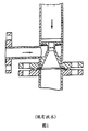
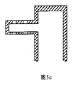
図3に示したように、本発明による高速混合反応器は、第1のフィードイン流路筐体1、反応器筐体4、第2のフィードイン流路17、中空羽根車フィード分配器6、回転シャフト10、および第1のフィード分配器3を主に備える。第1のフィードイン流路筐体1は、反応器筐体4に対して同軸に構築され、第1のフィードイン流路筐体1の端部に据え付けられた第1のフィード分配器3を介して、反応器筐体内部の反応空間と連通している。第2のフィードイン流路17、中空羽根車フィード分配器6、および回転シャフト10はそれぞれ、反応器の中心軸に沿って順番に互いに接続して固定されている。中空羽根車フィード分配器6は、反応器筐体4内に位置し、回転シャフト10の原動力下で軸方向に回転する。第2のフィードイン流路17は、中空羽根車フィード分配器6内部のフィード流路12と接続されている。第1のフィードイン流路筐体1には、少なくとも1つの第1のフィードイン入口2が備わっており、第1のフィードイン流路筐体1および第1のフィード分配器3は、第1のフィードイン流路18として画定される空間を囲繞する。反応器筐体4の遠位末端には、少なくとも1つの反応液出口8が備わっている。第1のフィード分配器3には、互いに釣り合った距離を有する複数の第1のフィードイン噴出孔13が備わっており、中空羽根車フィード分配器6には、その羽根車プレートに垂直な複数の流路が備わっている。羽根車プレートに垂直な流路にはすべて、複数の第2のフィードイン噴出孔5が備わっている。図5cは、羽根車プレートに垂直な流路の局所的な拡大であり、これは、図3に示したものと異なる程度に噴出孔のパターンを示す。あるいは、本発明による中空羽根車フィード分配器6は、図5a、5bに示したような、または本発明に適した任意の他のパターンで第2のフィードイン噴出孔とともに設計することができる。
As shown in FIG. 3, the high-speed mixing reactor according to the present invention includes a first feed-in
図3に示したように、中空羽根車フィード分配器6と第2のフィードイン流路17の間の接合部は、互いにしっかりと隣接する動的シールリング14および静的シールリング19で密閉されている。動的シールリング14は、中空羽根車フィード分配器6上に配置されており、静的シールリング19は、第2のフィードイン流路17の端部に配置されている。静的シールリング19の一方の側は、中空羽根車フィード分配器6上の動的シールリング14としっかりと隣接し、その他方の側は、伸縮継ぎ手16および伸縮継ぎ手16の外側に位置したバネ15を介して、第1のフィード分配器3に固定されている。この設計で、中空羽根車フィード分配器6上の動的シールリング14および第2のフィードイン流路17上の静的シールリング19が、互いにしっかりと隣接することによって結合部を密閉し、回転シャフト10が動作する際に第2のフィードが反応器筐体4の内部に漏れるのを防止する。
As shown in FIG. 3, the joint between the hollow
さらに、図3に示したように、中空羽根車フィード分配器6の下流に、環状反応流路調節ブロック7が反応器筐体4の内壁上に固定され、内側に突き出している。この設計は、反応混合物の流路をある特定の程度に狭くする目的がある。回転シャフト10には、これに垂直なステージ−I撹拌パドル11が備わっている。撹拌パドル11および反応流路調節ブロック7は、反応器の中心軸に垂直な同じ断面内に位置している。より好ましくは、本発明で記載される反応器は、反応器の遠位末端にモーター接続部9を備え、これは、モーターを反応器に固定するのに役立つ。
Further, as shown in FIG. 3, an annular reaction flow
図6a〜6cに示したように、第1のフィード分配器3内に配置された第1のフィードイン噴出孔13は、環状スリット、または均等に分布した複数の開口部とすることができ、ただし、噴出孔13を通じた下流の反応ゾーンへの第1のフィードの流入は均質である。
As shown in FIGS. 6 a to 6 c, the first feed-in ejection holes 13 arranged in the
図3に示した反応器を使用してイソシアネートの調製が実施される場合、最初に、ホスゲン溶液は、第1のフィードイン入口2を最初に通過し、第1のフィードイン流路18を満たす。次いで、ホスゲン溶液は、第1のフィード分配器3内で均等に分布した第1のフィードイン噴出孔13を通じて反応器筐体4に入る。同時に、一般式(I)に対応するポリアミンの有機溶液が第2のフィードイン流路17を通じて導入される。ポリアミン溶液は、回転中空羽根車フィード分配器6内部のフィード流路12を通じて流れ、複数の第2のフィードイン噴出孔5を介してホスゲン溶液のストリーム中に均等に噴出される。それによって、急速な混合および反応を実現することができる。得られた混合物は、送り圧力下で下流に進み、回転シャフト10に垂直な撹拌パドル11によって撹拌された後、反応液出口8を介して次段階の反応器に入る。目的とするイソシアネートは、次段階の反応器内での温度上昇によって形成される。
When the isocyanate preparation is carried out using the reactor shown in FIG. 3, first, the phosgene solution first passes through the first feed-in inlet 2 and fills the first feed-in
図4は、本発明の別の好適な実施形態による反応器の配列の概略図であり、これは、反応器が、第1のフィードイン流路筐体21、反応器筐体24、第2のフィードイン流路34、中空羽根車フィード分配器26、回転シャフト30、および第1のフィード分配器23を主に備えることを示す。第1のフィードイン流路筐体21は、反応器筐体24に対して同軸に構築され、第1のフィードイン流路筐体の端部に据え付けられた第1のフィード分配器23を介して、反応器筐体内部の反応空間と連通している。第2のフィードイン流路34は、回転シャフト30の内部に位置し、さらに、第2のフィードイン流路34、回転シャフト30、および中空羽根車フィード分配器26は、急速混合反応器の中心軸に沿って順番に互いに接続して固定されている。中空羽根車フィード分配器26は、回転シャフト30の一端部に固定され、その結果、中空羽根車フィード分配器26は、反応器筐体内部の回転シャフト30の原動力下で軸方向に回転することができる。第2のフィードイン流路は、中空羽根車フィード分配器26内部のフィード流路32と接続されている。第1のフィードイン流路筐体には、中に少なくとも1つの第1のフィードイン入口22が備わっており、第1のフィードイン流路筐体21および第1のフィード分配器23は、第1のフィードイン流路35として画定される空間を囲繞する。反応器筐体の遠位末端には、少なくとも1つの反応液出口28が備わっている。第1のフィード分配器23には、互いに釣り合った距離を有する複数の第1のフィードイン噴出孔33が備わっており、中空羽根車フィード分配器26には、その羽根車プレートに垂直な複数の流路が備わっている。羽根車プレートに垂直な流路にはすべて、複数の第2のフィードイン噴出孔25が備わっている。あるいは、本発明による中空羽根車フィード分配器は、図5a、5b、もしくは5cに示したように配列され、または本発明に適した任意の他のパターンで配列された第2のフィードイン噴出孔とともに設計することができる。
FIG. 4 is a schematic view of an arrangement of reactors according to another preferred embodiment of the present invention, in which the reactors are a first feed-in
さらに、図4に示したように、中空羽根車フィード分配器26の下流に、環状反応流路調節ブロック27が反応器筐体の内壁上に固定され、内側に突き出している。この設計は、反応混合物の流路をある特定の程度に狭くする目的がある。回転シャフト30には、ステージ−I撹拌パドル31が備わっており、撹拌パドル31および反応流路調節ブロック27は、反応器の中心軸に垂直な同じ断面内に位置している。より好ましくは、この好適な実施形態で記載される反応器は、反応器の遠位末端にモーター接続部29を備え、これは、反応器をモーターに固定するのに役立つ。
やはり、図4に示した反応器を使用してイソシアネートの調製が実施される場合、最初に、ホスゲン溶液は、第1のフィードイン入口22を通過し、第1のフィードイン流路35を満たす。次いで、ホスゲン溶液は、第1のフィード分配器23上で均等に分布した第1のフィードイン噴出孔33を通じて反応器筐体に入る。同時に、一般式(I)のポリアミンの有機溶液が回転シャフト内部の第2のフィードイン流路34を通じて導入される。ポリアミン溶液は、回転中空羽根車フィード分配器26内部のフィード流路32を通じて流れ、複数の第2のフィードイン噴出孔25を介してホスゲン溶液のストリーム中に均等に噴出される。それによって、急速な混合および反応を実現することができる。得られた混合物は、送り圧力下で下流に進み、回転シャフト30に垂直な撹拌パドル31によって撹拌された後、反応液用出口28を介して次段階の反応器に入る。目的とするイソシアネートは、次段階の反応器内での温度上昇によって形成される。
Further, as shown in FIG. 4, an annular reaction flow
Again, when the isocyanate preparation is carried out using the reactor shown in FIG. 4, first, the phosgene solution passes through the first feed-in
以下に、本発明による急速混合反応器およびその適用を、例としてさらに例示するが、本発明はこれらに決して限定されない。 In the following, the rapid mixing reactor according to the invention and its application are further illustrated by way of example, but the invention is in no way limited to these.
(例1)
図3に示した急速混合反応器を、MDI生産の実験に使用した。急速混合反応器の第1のフィード分配器を、図6cに示したように設計した。第1のフィード分配器において、20mmの直径を有する複数の円形流路を均等に分布させた。ホスゲン溶液は、6m/秒の出力レートで第1のフィード分配器の円形流路から出た。10mmの直径を有する第2のフィードイン噴出孔を、図5cに示したパターンで中空羽根車フィード分配器内に配置した。ポリアミン溶液は、16m/秒の出力レートで第2のフィードイン噴出孔から出た。回転シャフトは、1200rpmの回転速度で回転した。この反応器をMDIプラント内で使用して、1年あたり22万トンのMDI生成物の試験負荷下で試験した。クロロベンゼンを溶媒として使用し、33重量%の濃度のアミンのクロロベンゼン溶液を、1時間当たり24トンの割合で供給した。ホスゲン溶液の濃度は80%であった。アミンのクロロベンゼン溶液を回転中空羽根車フィード分配器によって反応器筐体内に噴出させ、第1のフィード分配器によって反応器筐体に入ったホスゲン溶液と急速に反応させた。2つの反応物の質量比は、ホスゲン:アミン=1.7:1であった。その後、反応器の出口で排出された反応混合物を、一連の4つの40m3のホスゲン化器(phosgenator)に移して、溶液が透明になるまで高温でホスゲン化させた。連続したこれらの4つのホスゲン化器の温度はそれぞれ、90℃、105℃、115℃、および120℃であった。粗生成物溶液をその後蒸留することによって重合したMDI生成物を得、これは、200cpの粘度、および31.62重量%のNCO含量を有していた。
(Example 1)
The rapid mixing reactor shown in FIG. 3 was used for experiments in MDI production. The first feed distributor of the rapid mixing reactor was designed as shown in Figure 6c. In the first feed distributor, a plurality of circular channels having a diameter of 20 mm were evenly distributed. The phosgene solution exited the circular flow path of the first feed distributor at an output rate of 6 m / sec. A second feed-in orifice having a diameter of 10 mm was placed in the hollow impeller feed distributor in the pattern shown in FIG. 5c. The polyamine solution exited from the second feed-in orifice at an output rate of 16 m / sec. The rotating shaft rotated at a rotation speed of 1200 rpm. The reactor was used in an MDI plant and tested under a test load of 220,000 tons of MDI product per year. Chlorobenzene was used as a solvent, and a 33 wt% concentration of amine in chlorobenzene was fed at a rate of 24 tons per hour. The concentration of the phosgene solution was 80%. The amine chlorobenzene solution was spouted into the reactor housing by a rotating hollow impeller feed distributor and rapidly reacted with the phosgene solution entering the reactor housing by a first feed distributor. The mass ratio of the two reactants was phosgene: amine = 1.7: 1. The reaction mixture discharged at the outlet of the reactor was then transferred to a series of four 40 m 3 phosgenators to phosgenate at elevated temperatures until the solution became clear. The temperatures of these four consecutive phosgenizers were 90 ° C, 105 ° C, 115 ° C, and 120 ° C, respectively. The crude product solution was then distilled to obtain a polymerized MDI product, which had a viscosity of 200 cp and an NCO content of 31.62% by weight.
(例2)
図3に示した急速混合反応器を、MDI生産の実験に使用した。急速混合反応器の第1のフィード分配器を、図6bに示したように設計した。第1のフィード分配器において、様々な内径および2mmの径方向幅を有する複数の弧状スリットを均等に分布させた。ホスゲン溶液は、10m/秒の出力レートで弧状スリットから出た。3mm×8mmの矩形孔サイズを有する第2のフィードイン噴出孔を、図5bに示したパターンで中空羽根車フィード分配器内に配置した。アミン溶液は、22m/秒の出力レートで第2のフィードイン噴出孔から出た。回転シャフトは、1400rpmの回転速度で回転した。この反応器をMDIプラント内で使用して、1年あたり30万トンのMDI生成物の試験負荷下で試験した。クロロベンゼンを溶媒として使用し、33重量%の濃度のアミンのクロロベンゼン溶液を、1時間当たり33トンの割合で供給した。ホスゲン溶液の濃度は75%であった。アミンのクロロベンゼン溶液を第2のフィード分配器によって反応器筐体内に噴出させ、第1のフィード分配器によって反応器筐体に入ったホスゲン溶液と急速に反応させた。2つの反応物の質量比は、ホスゲン:アミン=1.8:1であった。その後、反応器の出口で排出された反応混合物を、一連の4つの40m3のホスゲン化器に移して、溶液が透明になるまで高温でホスゲン化させた。これらの4つのホスゲン化器の温度はそれぞれ、90℃、105℃、115℃、および120℃であった。粗生成物溶液をその後蒸留することによって重合したMDI生成物を得、これは、200cpの粘度、および31.56重量%のNCO含量を有していた。
(Example 2)
The rapid mixing reactor shown in FIG. 3 was used for experiments in MDI production. The first feed distributor of the rapid mixing reactor was designed as shown in Figure 6b. In the first feed distributor, a plurality of arcuate slits having various inner diameters and a radial width of 2 mm were evenly distributed. The phosgene solution exited the arc slit at an output rate of 10 m / sec. A second feed-in jet hole having a 3 mm × 8 mm rectangular hole size was placed in the hollow impeller feed distributor in the pattern shown in FIG. 5b. The amine solution exited from the second feed-in orifice at an output rate of 22 m / sec. The rotating shaft rotated at a rotational speed of 1400 rpm. The reactor was used in an MDI plant and tested under a test load of 300,000 tons of MDI product per year. Chlorobenzene was used as a solvent and a 33% strength by weight amine chlorobenzene solution was fed at a rate of 33 tons per hour. The concentration of the phosgene solution was 75%. The amine chlorobenzene solution was spouted into the reactor housing by the second feed distributor and rapidly reacted with the phosgene solution entering the reactor housing by the first feed distributor. The mass ratio of the two reactants was phosgene: amine = 1.8: 1. The reaction mixture discharged at the outlet of the reactor was then transferred to a series of four 40 m 3 phosgenators and phosgenated at high temperature until the solution became clear. The temperatures of these four phosgenizers were 90 ° C, 105 ° C, 115 ° C, and 120 ° C, respectively. The crude product solution was then distilled to obtain a polymerized MDI product, which had a viscosity of 200 cp and an NCO content of 31.56% by weight.
上述した2つの実施例から、本発明による急速混合反応器は、33重量%もの高い濃度のアミン溶液、および1.7:1という低いホスゲンとアミンの質量比を用いてMDI生産に使用することができ、これは、広く使用されている従来の反応器(15〜22%の範囲のアミン溶液の濃度、および2.4〜4の範囲のホスゲンとアミンの質量比を用いる)に対してはるかに有利であることが分かる。溶媒およびホスゲンの体積の低減により、反応器の効率および全体的な能力が改善されるだけでなく、過剰なホスゲンの縮合および溶媒の蒸留除去(distil−out)のためのエネルギーも低減され、エネルギー消費量が、生成物1キログラム当たり40%低減される。 From the two examples described above, the rapid mixing reactor according to the present invention can be used for MDI production with amine solutions as high as 33% by weight and phosgene to amine mass ratios as low as 1.7: 1. This is much more than the widely used conventional reactors (using amine solution concentrations in the range of 15-22% and phosgene to amine mass ratios in the range of 2.4-4). It turns out that it is advantageous. Reducing the volume of solvent and phosgene not only improves the efficiency and overall capacity of the reactor, but also reduces the energy for condensation of excess phosgene and solvent distil-out. Consumption is reduced by 40% per kilogram of product.
(例3)
図4に示した急速混合反応器を、ポリメチレンポリフェニレンポリアミンの生産の実験に使用した。急速混合反応器の第1のフィード分配器を、図6bに示したように設計した。第1のフィード分配器において、様々な内径および6mmの径方向幅を有する複数の弧状スリットを均等に分布させた。アニリン塩酸塩と循環液の液体混合物は、5m/秒の出力レートで弧状スリットから出た。3mm×8mmの矩形孔サイズを有する第2のフィードイン噴出孔を、図5bに示したパターンで中空羽根車フィード分配器内に配置した。ホルムアルデヒド溶液は、20m/秒の出力レートで第2のフィードイン噴出孔から出た。回転シャフトは、2400rpmの回転速度で回転した。この反応器をポリメチレンポリフェニレンポリアミンのプラント内で使用して、1年あたり30万トンのポリアミンの試験負荷下で試験した。ホルムアルデヒド溶液(37重量%の濃度)を、1時間当たり16トンの割合で供給した。ホルムアルデヒド溶液を第2のフィード分配器によって反応器筐体内に噴出させ、第1のフィード分配器によって反応器筐体に入ったアニリン塩酸塩と循環液の液体混合物と急速に反応させた。塩酸(32重量%)と新鮮なアニリンのモル比は、0.36:1であり、ホルムアルデヒドと新鮮なアニリンのモル比は、0.52:1であり、アニリン塩酸塩と循環液の液体混合物の全流量は、220m3/時間であった。その後、反応器の出口で排出された反応混合物を、撹拌機を有する容器に移して、前縮合反応を65℃の反応温度で継続し、その後、加熱、分子転位、中和、水洗浄、ポリアミン精製などの工程を続けることによって、N−メチル含量が0.12%である精製ポリメチレンポリフェニレンポリアミン生成物を収集し、これは、製品品質の規格を満たした。
(Example 3)
The rapid mixing reactor shown in FIG. 4 was used for the production experiment of polymethylene polyphenylene polyamine. The first feed distributor of the rapid mixing reactor was designed as shown in Figure 6b. In the first feed distributor, a plurality of arcuate slits having various inner diameters and a radial width of 6 mm were evenly distributed. The liquid mixture of aniline hydrochloride and circulating fluid exited the arc slit at an output rate of 5 m / sec. A second feed-in jet hole having a 3 mm × 8 mm rectangular hole size was placed in the hollow impeller feed distributor in the pattern shown in FIG. 5b. The formaldehyde solution exited from the second feed-in orifice at an output rate of 20 m / sec. The rotating shaft rotated at a rotational speed of 2400 rpm. The reactor was used in a polymethylene polyphenylene polyamine plant and tested under a test load of 300,000 tons of polyamine per year. Formaldehyde solution (concentration of 37% by weight) was fed at a rate of 16 tons per hour. The formaldehyde solution was spouted into the reactor housing by the second feed distributor and rapidly reacted with the liquid mixture of aniline hydrochloride and circulating liquid that entered the reactor housing by the first feed distributor. The molar ratio of hydrochloric acid (32 wt%) to fresh aniline is 0.36: 1, the molar ratio of formaldehyde to fresh aniline is 0.52: 1, and the liquid mixture of aniline hydrochloride and circulating liquid The total flow rate of was 220 m 3 / hour. Thereafter, the reaction mixture discharged at the outlet of the reactor is transferred to a container having a stirrer, and the precondensation reaction is continued at a reaction temperature of 65 ° C., and then heating, molecular rearrangement, neutralization, water washing, polyamine By continuing with steps such as purification, a purified polymethylene polyphenylene polyamine product with an N-methyl content of 0.12% was collected, which met product quality specifications.
本発明による急速混合反応器は、前縮合反応温度を40℃から、孔噴出型の反応器が使用される場合、65℃まで上昇させることを可能にする。エネルギー消費量は35%低減し、混合が著しく改善されたので、目詰まりによる1カ月1回の反応器の掃除が排除された。したがって、生産設備全体の稼働率は、著しく増大した。 The rapid mixing reactor according to the invention makes it possible to raise the precondensation reaction temperature from 40 ° C. to 65 ° C. when a hole-jet reactor is used. Energy consumption has been reduced by 35% and mixing has been significantly improved, eliminating the need to clean the reactor once a month due to clogging. Therefore, the utilization rate of the entire production facility has increased significantly.
Claims (18)
前記第1のフィードイン流路筐体は、前記反応器筐体に対して同軸に構築され、前記第1のフィードイン流路筐体の端部に据え付けられた前記第1のフィード分配器を介して、前記反応器筐体内部の反応空間と連通しており;
前記第2のフィードイン流路、前記中空羽根車フィード分配器、および前記回転シャフトはそれぞれ、反応器の中心軸に沿って順番に互いに接続して固定されており、前記中空羽根車フィード分配器は、前記反応器筐体内に位置し、前記回転シャフトの原動力下で軸方向に回転し;
前記第2のフィードイン流路は、前記中空羽根車フィード分配器内部のフィード流路と接続されており;
前記第1のフィードイン流路筐体には、中に少なくとも1つの第1のフィードイン入口が備わっており、;
前記反応器筐体には、その遠位末端で少なくとも1つの反応液出口が備わっており;
前記第1のフィード分配器および前記中空羽根車フィード分配器にはそれぞれ、第1のフィードイン噴出孔(複数可)および第2のフィードイン噴出孔(複数可)が備わっている、反応器。 A rapid mixing reactor comprising a first feed-in channel housing, a reactor housing, a second feed-in channel, a hollow impeller feed distributor, a rotating shaft, and a first feed distributor,
The first feed-in flow channel housing is constructed coaxially with respect to the reactor housing, and the first feed-in flow channel housing is installed at an end of the first feed-in flow channel housing. Communicates with the reaction space inside the reactor housing via;
The second feed-in channel, the hollow impeller feed distributor, and the rotating shaft are each connected and fixed in order along the central axis of the reactor, and the hollow impeller feed distributor is fixed. Is located in the reactor housing and rotates axially under the driving force of the rotating shaft;
The second feed-in channel is connected to a feed channel inside the hollow impeller feed distributor;
Said first feed-in channel housing has at least one first feed-in inlet therein;
Said reactor housing is provided with at least one reaction outlet at its distal end;
A reactor in which the first feed distributor and the hollow impeller feed distributor are each provided with a first feed-in orifice (s) and a second feed-in orifice (s).
前記動的シールリングは、前記中空羽根車フィード分配器上に配置され、前記静的シールリングは、前記第2のフィードイン流路の前記端部に配置されており、前記静的シールリングの一方の側は、前記中空羽根車フィード分配器上の前記動的シールリングと隣接し、他方の側は、内側から外側に、伸縮継ぎ手およびバネを介して前記第1のフィード分配器に固定されていることを特徴とする、請求項2に記載の反応器。 A dynamic seal ring and a static seal ring, which may be tightly adjacent to each other, are disposed at a site where the hollow impeller feed distributor is connected to the second feed-in channel;
The dynamic seal ring is disposed on the hollow impeller feed distributor, and the static seal ring is disposed at the end of the second feed-in flow path, One side is adjacent to the dynamic seal ring on the hollow impeller feed distributor and the other side is fixed from the inside to the outside to the first feed distributor via a telescopic joint and a spring. The reactor according to claim 2, wherein
前記第1のフィードイン噴出孔が環状である場合、前記環状の第1のフィードイン噴出孔は、前記第1のフィード分配器に対して同心円状に配置された複数の弧状スリットを備え、同じおよび/または異なる内径(複数可)を有し、前記複数の弧状スリットは、互いに間隔を置いて離されており、
前記第1のフィードイン噴出孔が、均等に分布した複数の開口部を備える場合、前記開口部は、円形、三角形、菱形、台形、多角形、楕円、正方形、長方形、またはこれらの任意の組合せから選択される形状、好ましくは円形を有することを特徴とする、請求項1または6に記載の反応器。 A plurality of openings in which the first feed-in ejection holes are annular or evenly distributed;
When the first feed-in ejection hole is annular, the annular first feed-in ejection hole includes a plurality of arc-shaped slits arranged concentrically with respect to the first feed distributor, and the same And / or having different inner diameter (s), the plurality of arcuate slits being spaced apart from each other;
In the case where the first feed-in ejection holes include a plurality of openings that are evenly distributed, the openings are circular, triangular, rhombus, trapezoidal, polygonal, elliptical, square, rectangular, or any combination thereof. Reactor according to claim 1 or 6, characterized in that it has a shape selected from
R(NH2)n (I)
R(NCO)n (II)
式中、Rは、脂肪族、脂環式、または芳香族炭化水素基を表し、n=1、または≧2であり、
(a)ホスゲンの溶液を、前記第1のフィードイン入口を介して前記急速混合反応器の前記第1のフィードイン流路中に、次いで前記第1のフィード分配器によって前記反応器筐体中に導入する工程と;
(b)一般式(I)の前記アミン(複数可)の有機溶液を、第2のフィードイン流路を通じ、かつ回転中空羽根車フィード分配器を介して前記反応器筐体中に導入する工程と;
(c)工程(a)を介して導入されたホスゲンの溶液、および工程(b)を介して導入されたアミン(複数可)の溶液を、前記反応器筐体内で互いに急速に混合し、反応させ、生成された反応液を、反応液用出口を介して排出する工程と
を含む方法。 By using the reactor according to any one of claims 1 to 11, from the amine (s) of general formula (I) to the aliphatic, alicyclic or general formula (II), or A method for preparing an aromatic isocyanate comprising the steps of:
R (NH 2 ) n (I)
R (NCO) n (II)
Wherein R represents an aliphatic, alicyclic or aromatic hydrocarbon group, n = 1, or ≧ 2.
(A) A solution of phosgene is passed through the first feed-in inlet into the first feed-in channel of the rapid mixing reactor and then into the reactor housing by the first feed distributor. And introducing into the process;
(B) introducing an organic solution of the amine (s) of general formula (I) into the reactor housing through a second feed-in channel and through a rotating hollow impeller feed distributor. When;
(C) The solution of phosgene introduced via step (a) and the solution of amine (s) introduced via step (b) are rapidly mixed together in the reactor housing to react And a step of discharging the generated reaction solution through the reaction solution outlet.
式(I)および(II)中のnが、2〜4を表すことを特徴とする、請求項12に記載の方法。 The group R in formulas (I) and (II) is an aliphatic C2-C50 hydrocarbon group, alicyclic C2-C50 hydrocarbon group, or aromatic C6-C50 hydrocarbon group, preferably an aliphatic C4- C30 hydrocarbon group, alicyclic C4-C30 hydrocarbon group, or aromatic C6-C30 hydrocarbon group, more preferably aliphatic C5-C18 hydrocarbon group, alicyclic C5-C18 hydrocarbon group, or aromatic A group C6-C20 hydrocarbon group;
The process according to claim 12, characterized in that n in formulas (I) and (II) represents 2-4.
(A)アニリン塩酸塩と循環反応液のストリームとの液体混合物を、前記第1のフィードイン入口を介して前記急速混合反応器の前記第1のフィードイン流路中に、次いで前記第1のフィード分配器によって前記反応器筐体中に導入する工程と;
(B)ホルムアルデヒドの溶液を、前記第2のフィードイン流路を通じ、かつ前記回転中空羽根車フィード分配器を介して前記反応器筐体中に導入する工程と;
(C)アニリン塩酸塩と前記循環反応液の前記液体混合物、および前記ホルムアルデヒドの溶液を、前記反応器筐体内で急速な混合および前縮合にかけ、次いで撹拌しながら反応容器内に前記反応液を移して、前記前縮合を進めることによって縮合液体を得、その後、加熱、分子転位、中和、水洗浄、精製の工程を続けることによって、精製ポリメチレンポリフェニレンポリアミンを得る工程と
を含む方法。 A process for preparing a polymethylene polyphenylene polyamine from aniline by using the reactor according to any one of claims 1 to 11, comprising:
(A) A liquid mixture of aniline hydrochloride and a stream of circulating reaction liquid is passed through the first feed-in inlet into the first feed-in flow path of the rapid mixing reactor and then the first Introducing into the reactor housing by a feed distributor;
(B) introducing a solution of formaldehyde into the reactor housing through the second feed-in channel and through the rotating hollow impeller feed distributor;
(C) The liquid mixture of aniline hydrochloride and the circulating reaction liquid, and the formaldehyde solution are subjected to rapid mixing and precondensation in the reactor housing, and then the reaction liquid is transferred into a reaction vessel with stirring. And obtaining the condensed polymethylene polyphenylene polyamine by continuing the steps of heating, molecular rearrangement, neutralization, washing with water, and purification after proceeding with the precondensation.
Applications Claiming Priority (1)
| Application Number | Priority Date | Filing Date | Title |
|---|---|---|---|
| PCT/CN2010/080434 WO2012088671A1 (en) | 2010-12-29 | 2010-12-29 | Fast mixing reactor and use thereof |
Publications (3)
| Publication Number | Publication Date |
|---|---|
| JP2014509247A true JP2014509247A (en) | 2014-04-17 |
| JP2014509247A5 JP2014509247A5 (en) | 2015-01-22 |
| JP5850345B2 JP5850345B2 (en) | 2016-02-03 |
Family
ID=46382188
Family Applications (1)
| Application Number | Title | Priority Date | Filing Date |
|---|---|---|---|
| JP2013546549A Active JP5850345B2 (en) | 2010-12-29 | 2010-12-29 | Fast mixing reactor and its use |
Country Status (8)
| Country | Link |
|---|---|
| US (1) | US9138717B2 (en) |
| EP (1) | EP2486975B1 (en) |
| JP (1) | JP5850345B2 (en) |
| KR (1) | KR101499758B1 (en) |
| BR (1) | BR112012029403B1 (en) |
| HU (1) | HUE026867T2 (en) |
| SA (1) | SA111330016B1 (en) |
| WO (1) | WO2012088671A1 (en) |
Cited By (2)
| Publication number | Priority date | Publication date | Assignee | Title |
|---|---|---|---|---|
| JP2017520560A (en) * | 2014-06-24 | 2017-07-27 | コベストロ、ドイチュラント、アクチエンゲゼルシャフトCovestro Deutschland Ag | Method for producing diphenylmethane-based diamine and polyamine |
| JP2017520564A (en) * | 2014-06-24 | 2017-07-27 | コベストロ、ドイチュラント、アクチエンゲゼルシャフトCovestro Deutschland Ag | Method for producing diphenylmethane-based diamine and polyamine |
Families Citing this family (16)
| Publication number | Priority date | Publication date | Assignee | Title |
|---|---|---|---|---|
| KR101577760B1 (en) * | 2013-08-23 | 2015-12-15 | 금호석유화학 주식회사 | Mixing reactor for heterogeneous fluids using high-speed ejecting |
| KR101452423B1 (en) * | 2013-12-10 | 2014-10-22 | 금호석유화학 주식회사 | Mixing reactor for heterogeneous fluids using high-speed ejecting |
| JP5815087B2 (en) | 2013-12-10 | 2015-11-17 | コリア クムホ ペトロケミカル カンパニー., リミテッド | Mixing reactor of different fluids using high speed injection |
| KR101416760B1 (en) * | 2014-03-25 | 2014-07-09 | 금호석유화학 주식회사 | Mixing reactor for preparing isocyanates using high-speed ejecting |
| PT3160934T (en) | 2014-06-24 | 2022-04-20 | Covestro Intellectual Property Gmbh & Co Kg | Process for preparation of di- and polyamines of the diphenylmethane series |
| CN105198099A (en) * | 2015-10-23 | 2015-12-30 | 宜兴汉光高新石化有限公司 | Stirring device for producing high-efficiency hydrogenation scale inhibitor |
| CN107597028B (en) * | 2017-09-21 | 2020-05-08 | 万华化学(宁波)有限公司 | Reactor and method for preparing isocyanate |
| CN108905842B (en) * | 2018-06-25 | 2021-08-27 | 山东大学 | Rhodamine B fluorescent tracer full-automatic configuration and feeding control device and operation method |
| CN109126681B (en) * | 2018-10-16 | 2025-02-18 | 海南行者新材料科技有限公司 | A pipeline vibration type material reaction device |
| CN109663546B (en) * | 2019-02-21 | 2022-09-06 | 南京科技职业学院 | Special reactor for synthesizing acetanilide |
| KR102025042B1 (en) * | 2019-03-06 | 2019-09-24 | 곽동채 | High-speed instant-mixing liquid-phase polymer melting device |
| EA202100032A3 (en) * | 2020-02-21 | 2021-10-29 | Вингфлоу Аг | REACTOR FOR PRODUCING MICRONIZED SILICA GEL |
| CN115286535B (en) * | 2022-08-17 | 2023-10-17 | 万华化学集团股份有限公司 | Isocyanate preparation process and salifying and photochemical reaction coupling device |
| CN115634655B (en) * | 2022-11-04 | 2025-05-16 | 万华化学集团股份有限公司 | A high shear mixing reactor and a method for preparing diphenylmethane series amines |
| CN116271935B (en) * | 2023-03-16 | 2024-02-23 | 福建省德旭新材料有限公司 | Cooler for preparing sodium hexafluorophosphate |
| CN116492930B (en) * | 2023-06-05 | 2025-11-18 | 福建永荣锦江股份有限公司 | A mixing reaction apparatus and reaction method for preparing polyamide 66 salt. |
Citations (9)
| Publication number | Priority date | Publication date | Assignee | Title |
|---|---|---|---|---|
| US2392542A (en) * | 1942-10-05 | 1946-01-08 | Phillips Petroleum Co | Apparatus for mixing fluids |
| JPS4941029B1 (en) * | 1970-05-28 | 1974-11-06 | ||
| JPS54162269A (en) * | 1978-06-12 | 1979-12-22 | Ihara Chemical Ind Co | Liquid rapid mixer |
| JPS63296830A (en) * | 1987-05-21 | 1988-12-02 | バイエル・アクチエンゲゼルシヤフト | Mixer for mixing at least two flowable substances while reaction is generated or started during mixing |
| JPS63303961A (en) * | 1987-05-21 | 1988-12-12 | バイエル・アクチエンゲゼルシヤフト | Manufacture of isocyanate |
| JP2001000851A (en) * | 1999-05-27 | 2001-01-09 | Ekato Ruhr & Mischtechnik Gmbh | mixer |
| JP2002502838A (en) * | 1998-02-07 | 2002-01-29 | ビーエーエスエフ アクチェンゲゼルシャフト | Method for producing methylene dianiline and methylene bis (phenyl isocyanate) |
| JP2003313155A (en) * | 2002-03-13 | 2003-11-06 | Bayer Ag | Polyamine of diphenylmethane series and method for producing polyisocyanate |
| JP2008510607A (en) * | 2004-08-23 | 2008-04-10 | アイトゲネシッシェ テヒニッシェ ホーホシューレ チューリッヒ | Method for forming finely dispersed micronanoemulsion with narrow droplet size distribution while mechanically protecting and apparatus for carrying out this method |
Family Cites Families (29)
| Publication number | Priority date | Publication date | Assignee | Title |
|---|---|---|---|---|
| US1152769A (en) * | 1912-06-12 | 1915-09-07 | Lamartine C Trent | Apparatus for treating solid-bearing solutions. |
| US2402905A (en) * | 1943-09-14 | 1946-06-25 | Girdler Corp | Mixing apparatus |
| US2904407A (en) * | 1956-11-01 | 1959-09-15 | Klauder Weldon Giles Machine C | Chemical reactor |
| US3226205A (en) * | 1960-10-03 | 1965-12-28 | Phillips Petroleum Co | Reactor impeller with feed inlet along shaft |
| DE3116878C2 (en) | 1981-04-28 | 1985-07-18 | Institut Biochimii I Fiziologii Mikroorganizmov Akademii Nauk Sssr | Device for growing microorganisms |
| CA1284017C (en) * | 1987-05-21 | 1991-05-14 | Hugo I. De Lasa | Riser simulator |
| DE3744001C1 (en) | 1987-12-24 | 1989-06-08 | Bayer Ag | Process for the continuous production of mono- or polyisocyanates |
| US5620250A (en) * | 1996-03-05 | 1997-04-15 | Pro-Quip, Inc. | Jet mixer having a self-centering liquid bearing hub arrangement |
| DE19638567A1 (en) | 1996-09-20 | 1998-03-26 | Bayer Ag | Mixer reactor and process for carrying out reactions, in particular the phosgenation of primary amines |
| US5811259A (en) * | 1997-07-29 | 1998-09-22 | Ecomat, Inc. | Biochemical reactor |
| US6386751B1 (en) * | 1997-10-24 | 2002-05-14 | Diffusion Dynamics, Inc. | Diffuser/emulsifier |
| US20110075507A1 (en) * | 1997-10-24 | 2011-03-31 | Revalesio Corporation | Diffuser/emulsifier |
| US7654728B2 (en) * | 1997-10-24 | 2010-02-02 | Revalesio Corporation | System and method for therapeutic application of dissolved oxygen |
| JP2001239140A (en) * | 1999-12-22 | 2001-09-04 | Reika Kogyo Kk | Reaction stirrer, reaction fractionation filtration device and fractionation method, production method, filtration method |
| CN1194962C (en) | 2000-12-29 | 2005-03-30 | K·S·T·公司 | Method and apparatus for continuously preparing tolylene diisocyanate |
| DE10359627A1 (en) | 2003-12-18 | 2005-07-21 | Bayer Materialscience Ag | Process for the preparation of diisocyanates |
| JP3746288B2 (en) * | 2004-07-27 | 2006-02-15 | ファルクサー株式会社 | Method of combining powder raw material and liquid raw material and mixer |
| CN101153015B (en) * | 2006-09-28 | 2010-06-16 | 宁波万华聚氨酯有限公司 | Hole shooting flow type reactor and method for producing isocyanic ester by using the reactor |
| US7455776B2 (en) * | 2006-11-21 | 2008-11-25 | Praxair Technology, Inc. | Method for mixing high viscous liquids with gas |
| CN101209405B (en) * | 2006-12-27 | 2013-08-28 | 宁波万华聚氨酯有限公司 | Hole jet type injecting reactor |
| US7677791B2 (en) | 2007-01-23 | 2010-03-16 | Joseph Carl Firey | Rotary residual fuel slurrifier |
| WO2008122148A1 (en) | 2007-04-06 | 2008-10-16 | Ningbo Wanhua Polyurethanes Co., Ltd. | A process for preparation of polymethylene polyphenyl polyamine |
| US9205388B2 (en) * | 2007-06-27 | 2015-12-08 | H R D Corporation | High shear system and method for the production of acids |
| DE102007061688A1 (en) * | 2007-12-19 | 2009-06-25 | Bayer Materialscience Ag | Process and mixing unit for the production of isocyanates by phosgenation of primary amines |
| US8119084B2 (en) * | 2008-05-16 | 2012-02-21 | Exxonmobil Research & Engineering Company | Reactor for isoparaffin olefin alkylation |
| DE102008063728A1 (en) | 2008-12-18 | 2010-06-24 | Bayer Materialscience Ag | Process for the preparation of isocyanates in the gas phase |
| US20110028573A1 (en) * | 2009-07-28 | 2011-02-03 | Hrd Corp. | High Shear Production of Value-Added Product From Refinery-Related Gas |
| CN101811019B (en) | 2010-04-19 | 2012-01-18 | 烟台万华聚氨酯股份有限公司 | Dynamic hole jet reactor and method for preparing isocyanate by adopting dynamic hole jet reactor |
| CN101811017B (en) | 2010-04-23 | 2012-01-11 | 烟台万华聚氨酯股份有限公司 | Stirring and grinding reactor and method for preparing isocyanate with same |
-
2010
- 2010-12-29 EP EP10852321.8A patent/EP2486975B1/en active Active
- 2010-12-29 US US13/499,703 patent/US9138717B2/en active Active
- 2010-12-29 WO PCT/CN2010/080434 patent/WO2012088671A1/en not_active Ceased
- 2010-12-29 BR BR112012029403-2A patent/BR112012029403B1/en active IP Right Grant
- 2010-12-29 HU HUE10852321A patent/HUE026867T2/en unknown
- 2010-12-29 JP JP2013546549A patent/JP5850345B2/en active Active
- 2010-12-29 KR KR1020137018951A patent/KR101499758B1/en active Active
-
2011
- 2011-11-30 SA SA111330016A patent/SA111330016B1/en unknown
Patent Citations (9)
| Publication number | Priority date | Publication date | Assignee | Title |
|---|---|---|---|---|
| US2392542A (en) * | 1942-10-05 | 1946-01-08 | Phillips Petroleum Co | Apparatus for mixing fluids |
| JPS4941029B1 (en) * | 1970-05-28 | 1974-11-06 | ||
| JPS54162269A (en) * | 1978-06-12 | 1979-12-22 | Ihara Chemical Ind Co | Liquid rapid mixer |
| JPS63296830A (en) * | 1987-05-21 | 1988-12-02 | バイエル・アクチエンゲゼルシヤフト | Mixer for mixing at least two flowable substances while reaction is generated or started during mixing |
| JPS63303961A (en) * | 1987-05-21 | 1988-12-12 | バイエル・アクチエンゲゼルシヤフト | Manufacture of isocyanate |
| JP2002502838A (en) * | 1998-02-07 | 2002-01-29 | ビーエーエスエフ アクチェンゲゼルシャフト | Method for producing methylene dianiline and methylene bis (phenyl isocyanate) |
| JP2001000851A (en) * | 1999-05-27 | 2001-01-09 | Ekato Ruhr & Mischtechnik Gmbh | mixer |
| JP2003313155A (en) * | 2002-03-13 | 2003-11-06 | Bayer Ag | Polyamine of diphenylmethane series and method for producing polyisocyanate |
| JP2008510607A (en) * | 2004-08-23 | 2008-04-10 | アイトゲネシッシェ テヒニッシェ ホーホシューレ チューリッヒ | Method for forming finely dispersed micronanoemulsion with narrow droplet size distribution while mechanically protecting and apparatus for carrying out this method |
Cited By (2)
| Publication number | Priority date | Publication date | Assignee | Title |
|---|---|---|---|---|
| JP2017520560A (en) * | 2014-06-24 | 2017-07-27 | コベストロ、ドイチュラント、アクチエンゲゼルシャフトCovestro Deutschland Ag | Method for producing diphenylmethane-based diamine and polyamine |
| JP2017520564A (en) * | 2014-06-24 | 2017-07-27 | コベストロ、ドイチュラント、アクチエンゲゼルシャフトCovestro Deutschland Ag | Method for producing diphenylmethane-based diamine and polyamine |
Also Published As
| Publication number | Publication date |
|---|---|
| US20130178596A1 (en) | 2013-07-11 |
| EP2486975A4 (en) | 2012-09-12 |
| EP2486975B1 (en) | 2015-09-23 |
| KR20130099200A (en) | 2013-09-05 |
| BR112012029403B1 (en) | 2018-11-27 |
| EP2486975A1 (en) | 2012-08-15 |
| HUE026867T2 (en) | 2016-08-29 |
| KR101499758B1 (en) | 2015-03-06 |
| BR112012029403A2 (en) | 2016-12-06 |
| WO2012088671A1 (en) | 2012-07-05 |
| JP5850345B2 (en) | 2016-02-03 |
| US9138717B2 (en) | 2015-09-22 |
| SA111330016B1 (en) | 2015-01-27 |
Similar Documents
| Publication | Publication Date | Title |
|---|---|---|
| JP5850345B2 (en) | Fast mixing reactor and its use | |
| US9975094B2 (en) | Reactive flow static mixer with cross-flow obstructions | |
| JP2014509247A5 (en) | ||
| CN101811017B (en) | Stirring and grinding reactor and method for preparing isocyanate with same | |
| US8957245B2 (en) | Method for producing isocyanate | |
| JP5334558B2 (en) | Process and mixing unit for producing isocyanates by phosgenation of primary amines | |
| JP5595271B2 (en) | JET REACTION APPARATUS PROVIDED WITH FLOW DUCT AND METHOD FOR PRODUCING ISocyanates USING JET REACTION APPARATUS HAVING FLOW DUCT | |
| CN101104595B (en) | A kind of method for preparing isocyanate | |
| CN101735109B (en) | Process for the continuous production of organic isocyanates | |
| CN101848890B (en) | Method for producing isocyanates | |
| JP2005126437A (en) | Process for the preparation of isocyanates in the gas phase | |
| CN101747231B (en) | Process for preparing isocyanate in gas phase | |
| US9295972B2 (en) | Mixing reactor for heterogeneous fluids using high-speed ejecting | |
| CN211586574U (en) | High-efficiency film reactor | |
| CN102527312B (en) | Fast mixing reactor and application thereof | |
| CN104496852B (en) | A kind of continuous preparation of toluene diisocyanate Chuan-shaped high-gravity device and process | |
| WO2009068920A1 (en) | Mixing device for mixing two liquids and process for the continuous preparation of organic mono-, di- or polyisocyanates | |
| JP2023554659A (en) | Batch reactor | |
| KR20220088139A (en) | Batch reactor | |
| PL188027B1 (en) | Continuous method of obtaining toluenediisocyanate and system therefor |
Legal Events
| Date | Code | Title | Description |
|---|---|---|---|
| A977 | Report on retrieval |
Free format text: JAPANESE INTERMEDIATE CODE: A971007 Effective date: 20140718 |
|
| A131 | Notification of reasons for refusal |
Free format text: JAPANESE INTERMEDIATE CODE: A131 Effective date: 20140901 |
|
| A524 | Written submission of copy of amendment under article 19 pct |
Free format text: JAPANESE INTERMEDIATE CODE: A524 Effective date: 20141201 |
|
| A131 | Notification of reasons for refusal |
Free format text: JAPANESE INTERMEDIATE CODE: A131 Effective date: 20150629 |
|
| A521 | Request for written amendment filed |
Free format text: JAPANESE INTERMEDIATE CODE: A523 Effective date: 20150928 |
|
| TRDD | Decision of grant or rejection written | ||
| A01 | Written decision to grant a patent or to grant a registration (utility model) |
Free format text: JAPANESE INTERMEDIATE CODE: A01 Effective date: 20151105 |
|
| A61 | First payment of annual fees (during grant procedure) |
Free format text: JAPANESE INTERMEDIATE CODE: A61 Effective date: 20151119 |
|
| R150 | Certificate of patent or registration of utility model |
Ref document number: 5850345 Country of ref document: JP Free format text: JAPANESE INTERMEDIATE CODE: R150 |
|
| R250 | Receipt of annual fees |
Free format text: JAPANESE INTERMEDIATE CODE: R250 |
|
| R250 | Receipt of annual fees |
Free format text: JAPANESE INTERMEDIATE CODE: R250 |
|
| R250 | Receipt of annual fees |
Free format text: JAPANESE INTERMEDIATE CODE: R250 |
|
| R250 | Receipt of annual fees |
Free format text: JAPANESE INTERMEDIATE CODE: R250 |
|
| R250 | Receipt of annual fees |
Free format text: JAPANESE INTERMEDIATE CODE: R250 |
|
| R250 | Receipt of annual fees |
Free format text: JAPANESE INTERMEDIATE CODE: R250 |
|
| R250 | Receipt of annual fees |
Free format text: JAPANESE INTERMEDIATE CODE: R250 |
|
| R250 | Receipt of annual fees |
Free format text: JAPANESE INTERMEDIATE CODE: R250 |