JP2017006292A - Suspension tool and kite - Google Patents
Suspension tool and kite Download PDFInfo
- Publication number
- JP2017006292A JP2017006292A JP2015123599A JP2015123599A JP2017006292A JP 2017006292 A JP2017006292 A JP 2017006292A JP 2015123599 A JP2015123599 A JP 2015123599A JP 2015123599 A JP2015123599 A JP 2015123599A JP 2017006292 A JP2017006292 A JP 2017006292A
- Authority
- JP
- Japan
- Prior art keywords
- connecting member
- hook body
- bag
- load
- mounting member
- Prior art date
- Legal status (The legal status is an assumption and is not a legal conclusion. Google has not performed a legal analysis and makes no representation as to the accuracy of the status listed.)
- Granted
Links
Images


Landscapes
- Purses, Travelling Bags, Baskets, Or Suitcases (AREA)
Abstract
Description
本発明は、吊下対象物を吊り下げるための吊下具及び当該吊下具を具備する鞄に関するものである。 The present invention relates to a suspending tool for suspending a suspending object and a saddle equipped with the suspending tool.
従来、内容物を内部に収容するための鞄を利用するとき、収容部を有する鞄本体内に収容する荷物とは別に、鞄本体の外面に一部の荷物を吊り下げる、所謂吊下対象物として取り扱うことができるようにするための吊下具が提案されている。とくに鞄本体が、就学児童が背中に背負うことを目的とする所謂ランドセルである場合では、殆どのものが前記吊下具を設けることにより、鞄として取り扱われている(例えば、特許文献1及び特許文献2参照)。
Conventionally, when using a bag for storing contents inside, a so-called suspended object that hangs part of the baggage on the outer surface of the bag main body separately from the bag stored in the bag main body having the storage portion Suspension devices have been proposed to enable handling of the device. In particular, in the case where the main body of the bag is a so-called school bag intended for a schoolchild to carry on his / her back, most of the bag is handled as a bag by providing the hanging device (for example,
そして上述したような吊下具を使用する場合には従前より、吊下具に吊り下げられた吊下対象物が例えば使用者の移動中などにおいて不意に他の物に引っ掛かってしまい、このときに鞄本体に加わる大きな外力のために使用者の姿勢が大きく崩れてしまうといった現象が懸念されている。そこで上記各特許文献では、斯かる現象を回避すべく、上述のような大きな外力が生じたとき、吊下具の一部又は全部が鞄本体から吊下対象物ごと離脱し得る構成を適用している。 And when using the hanging tool as described above, the hanging object suspended from the hanging tool is unexpectedly caught by another object during the movement of the user, for example. In addition, there is a concern that the posture of the user may be greatly collapsed due to a large external force applied to the bag body. Therefore, in each of the above patent documents, in order to avoid such a phenomenon, when a large external force as described above is generated, a configuration in which a part or all of the hanging tool can be detached from the bag main body together with the suspended object is applied. ing.
しかしながら特許文献1に記載のものは、上記外力が生じたときには、鞄本体に固定した取付部材を変形させることにより当該取付部材に掛けられたフック体を取付部材から離脱させる態様を適用しているため、繰り返しフック体が離脱するような場合は取付部材の強度が疲労により低下してしまう。そして当該取付部材は鞄本体を構成する素材の外面にリベット等により強固に固定されているため、取付部材の交換するときには特別な工具や手順を要するために鞄本体ごと修理の対象となり、使用者が使用出来ない期間を招来してしまう。また同文献に記載のものでは、外力が作用する方向によって取付部材に対するフック体の相対位置が異なるため、取付部材を変形させてフック体を離脱させるに足る荷重の大きさは、上記外力が作用する方向によって大きくばらつきがあるのが現状である。
However, the thing of
また特許文献2に記載のものは、鞄本体側の取付部材とフック体とを、弾性変形課の連結杆(9)により接続しており、この連結杆が適宜フック体を離脱させることにより上記外力が生じても取付部材を損傷する不具合は起こり難い。しかしながら当該連結杆は取付部材及びフック体を所定の相対位置で固定する態様を適用しているため、上記外力が作用する方向によって、フック体を離脱させるのに要する荷重の大きさに大きくばらつきがあるのが現状である。
Moreover, the thing of the
本発明は、このような不具合に着目したものであり、フック体に何れの方向から外力が加わっても同じ荷重で鞄本体からフック体が外れるようにすることができる吊下具及び鞄を提供することを目的としている。 The present invention pays attention to such a problem, and provides a hanging tool and a heel that can cause the hook body to be detached from the heel body with the same load even if an external force is applied to the hook body from any direction. The purpose is to do.
本発明は、このような目的を達成するために、次のような手段を講じたものである。 In order to achieve such an object, the present invention takes the following measures.
すなわち本発明に係る吊下具は、鞄本体に設けられた取付部材に掛止めされる連結部材と、この連結部材を介して前記取付部材に取付けられるフック体とを具備してなり、前記連結部材が、前記フック体に作用する荷重の方向に応じて首振り動作を行うように構成されるとともに前記フック体に一定以上の引張り荷重が作用した場合に変形し又は破壊されて前記フック体を前記取付部材に対して離脱させるように強度設定されたものであることを特徴とする。 That is, the hanging tool according to the present invention includes a connecting member that is hooked to an attaching member provided on the heel body, and a hook body that is attached to the attaching member via the connecting member. The member is configured to swing in accordance with the direction of the load acting on the hook body, and is deformed or destroyed when a tensile load of a certain level or more is applied to the hook body. The strength is set so as to be separated from the mounting member.
また本発明に係る鞄は、取付部材を備えた鞄本体と、当該吊下具とを具備してなることを特徴とする。 Moreover, the scissors according to the present invention are characterized by comprising a scissors main body provided with a mounting member and the hanging tool.
このようなものであれば、連結部材が荷重の方向に応じて首振動作可能に構成されているため、荷重を受ける連結部材の姿勢が荷重の方向によって変化してしまうことが抑制される。これにより、荷重の方向が変わっても連結部材に対し予め設定された強度に応じた荷重でフック体を離脱させることができる。すなわち本発明によれば、フック体に何れの方向から外力が加わっても同じ荷重で鞄本体からフック体が外れるようにすることができる吊下具及び鞄を提供することができる。加えて本発明によれば、連結部材を取り替えることでフック体が外れた後でも再度外れる前と同じ状態に容易に復元させることができる。すなわち大掛かりな修理等を強いられる取付部材の交換を行うことなく継続して使用することができる。 If it is such, since the connection member is comprised so that a swing operation | movement is possible according to the direction of a load, it will be suppressed that the attitude | position of the connection member which receives a load changes with the directions of a load. Thereby, even if the direction of a load changes, a hook body can be made to detach | leave with the load according to the intensity | strength preset with respect to the connection member. That is, according to the present invention, it is possible to provide a suspending tool and a heel that can cause the hook body to be detached from the heel body with the same load even if an external force is applied to the hook body from any direction. In addition, according to the present invention, it is possible to easily restore the same state as before the hook body is removed again by replacing the connecting member. That is, it can be used continuously without exchanging the mounting members that are forced to undergo major repairs.
連結部材の強度設定を容易且つ正確に行い得るようにするためには、連結部材を、変形可能な樹脂製のものとすることが望ましい。 In order to be able to easily and accurately set the strength of the connecting member, the connecting member is preferably made of a deformable resin.
そしてフック体の着脱を容易なものとしつつ当該フック体の着脱を繰り返しても荷重によりフック体を離脱させるときの荷重の値に影響を及ぼさないようにし得る態様として、連結部材が、取付部材に掛けられる上端部及びフック体に係わり合う下端部を備えた一部に開口を有した輪状の連結部材本体と、この連結部材の開口に臨設され当該開口を取付部材又はフック体が通過するときに他の部位よりも優先して変形可能に設けられた先端が開放端である片持ち薄肉部とを備えたものである態様を挙げることができる。 And as a mode that makes it easy to attach and detach the hook body, and the repeated attachment and detachment of the hook body does not affect the load value when the hook body is detached by the load, the connecting member is attached to the mounting member. A ring-shaped connecting member main body having an opening in a part thereof having an upper end portion to be hung and a lower end portion engaged with the hook body, and when the mounting member or the hook body passes through the opening of the connecting member. A mode in which the tip provided in a deformable manner with priority over the other parts is provided with a cantilevered thin portion having an open end can be mentioned.
ここで、本発明の「フック体」とは、吊下対象物を吊り下げ得る形状をなすものであれば、いわゆるS字フックと称されるような概略S字状をなす線材や線材を一周或いは二周以上円周状に成形した掛け止め用のリングやクリップといったものも勿論含まれる。なかでも特に、吊下対象物の取り扱いを容易にして使用し易い吊下具を構成するためには、フック体を、輪の一部が開閉し、吊下対象物を押し込むことにより連結可能に構成されたナス環とすることが好ましい。 Here, as long as the “hook body” of the present invention has a shape capable of suspending a suspended object, a wire or wire having a substantially S shape as a so-called S-shaped hook is made around the circuit. Or the thing of the ring and clip for latching shape | molded by the circumference shape more than two times is also included. In particular, in order to construct a hanging tool that facilitates handling and handling of a suspended object, the hook body can be connected by opening and closing a part of the ring and pushing the suspended object. The constituted eggplant ring is preferable.
ここで、ナス環とは、引っ掛けてつなぐのに使う、卵形の金属製の輪のことを指す。そして勿論当該ナス環には、カラビナといった岩登りにも用いられ得るような、ハーケンとザイルとを連絡するために強度を設定された、一部がばね式で開閉できる金属製の輪も含まれる。 Here, the eggplant ring refers to an egg-shaped metal ring used for hooking and connecting. And of course, the eggplant ring also includes a metal ring that can be used to climb rocks, such as carabiner, and is partly spring-operated, with strength set to connect Harken and Zile. .
特に、フック体に掛かる外力により鞄の使用者の姿勢を崩してしまうといった現象を有効に回避することができる態様として鞄本体を、外側面に取付部材を備えたランドセルとした態様を挙げることができる。 In particular, as an aspect that can effectively avoid the phenomenon that the posture of the user of the bag is destroyed due to an external force applied to the hook body, an embodiment in which the bag body is a school bag having an attachment member on the outer side surface can be given. it can.
また、フック体に加わる外力を安定して連結部材に伝達させ得る態様として、取付部材が、外面にリベットを用いて止着された態様を挙げることができる。 Further, as an aspect in which an external force applied to the hook body can be stably transmitted to the connecting member, an aspect in which the attachment member is fixed to the outer surface using a rivet can be exemplified.
また取付部材及び鞄本体の強度の維持と、連結部材の安定した首振動作とを両立させるためには、取付部材を、線材を環状に成形し基端部側をプレスにより平らに成形した外面に密着するプレス領域と、線材自体の断面形状を維持しながら外面から離間するように成形した線状領域とを有するものとすることが望ましい。 Also, in order to maintain both the strength of the mounting member and the collar body and the stable swinging motion of the connecting member, the mounting member has an outer surface in which the wire is formed in an annular shape and the base end side is formed flat by pressing. It is desirable to have a press region that is in close contact with the wire and a linear region that is shaped so as to be separated from the outer surface while maintaining the cross-sectional shape of the wire itself.
そして連結部材の首振動作を円滑に行わせ得る取付部材の具体的な態様として、記線状領域の先端で連結部材を支持するとともに連結部材が線状領域と外面との間のスペースを利用して首振動作する態様を挙げることができる。 As a specific aspect of the mounting member that can smoothly perform the swinging operation of the connecting member, the connecting member is supported at the tip of the linear region and the connecting member uses a space between the linear region and the outer surface. Then, a mode of swinging can be mentioned.
本発明によれば、フック体に何れの方向から外力が加わっても同じ荷重で鞄本体からフック体が外れるようにすることができる吊下具及び鞄を提供することができる。 ADVANTAGE OF THE INVENTION According to this invention, even if an external force is applied to a hook body from which direction, the hanging tool and heel which can make a hook body remove | deviate from a heel main body with the same load can be provided.
以下、本発明の一実施の形態について図面を参照して説明する。 Hereinafter, an embodiment of the present invention will be described with reference to the drawings.
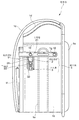
本実施形態に係る鞄は、図1に示すように、例えば就学児童が通学時に背負って使用するランドセルとして取り扱われる鞄本体1と、この鞄本体1に取り付けられた吊下具5とを有するものである。ここで、本実施形態では鞄本体1自体を「ランドセル」と称するものとして以下記載するが勿論、当該鞄本体1と吊下具5とを有する鞄そのものを「ランドセル」と称する態様を否定するものではない。
As shown in FIG. 1, the kite according to the present embodiment includes, for example, a
鞄本体1は、皮革或いは人工皮革素材を適宜縫製或いはリベット10等によりカシメることにより成形されたもので、例えば前面側で使用者の背中に密着する背当て1aと、この背当て1a後方に箱状に成形された収容部1bと、背当て1aの上端を基端とし、収容部1bの上方及び後方から覆う被せ蓋1cと、背当て1aの上下端を環状につなぐように対をなして設けられ使用者の肩を周回する図示しない肩ベルトとを有する通常のランドセルとして好適に利用され得るものである。そして収容部1bは、上方に向いた取出口1dと、両側面を若干の撓み変形を可能に設けたマチ1eと、後ろ側に別途ポケット等を設けた後面板1fと、この後面板1fからマチ1eに亘って補強する目的で強固に縫いつけ及びカシメにより取り付けられた帯状体1gとを有している。この帯状体1gには2箇所のリベット10が止着されており、帯状体1g前端に設けられたリベット10は、マチ1eに対し直接固定するために設けられ、図示後ろ側に設けられたリベット10はマチ1eには固定されておらず、専らマチ1eの外側面に取付部材11を強固に固定するためのものである。
The
ここで、本実施形態に係る吊下具5は、鞄本体1に設けられた取付部材11に掛止めされる連結部材2と、この連結部材2を介して取付部材11に取付けられるナス環3たるナス環3とを具備してなり、連結部材2が、ナス環3に作用する荷重の方向に応じて首振り動作を行うように構成されるとともにナス環3に一定以上の引張り荷重が作用した場合に変形し又は破壊されてナス環3を取付部材11に対して離脱させるように強度設定されたものであることを特徴とする。また上述の通り、本実施形態に係る鞄は当該吊下具5と、取付部材11を有する鞄本体1とを具備する。
Here, the suspending
以下、鞄本体1が具備する取付部材11、及び吊下具5の構成について図1〜図6を参照しつつ説明する。
Hereinafter, the structure of the
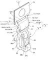
取付部材11は、図1〜図6に示すように、例えば鋼製の線材に曲げ加工及びプレス加工を施すことによって形成されたもので、プレス加工が施されたプレス領域11aが、収容部1bのマチ1e及び帯状体1gの間にマチ1eの外面に密着しながら位置付けられることで、帯状体1gが外方に不要に膨らむことを回避している。当該プレス領域11aには、鞄本体1を構成する素材の外面にリベット10を用いて止着されるための固定穴14を形成すべく環状に形成された環状プレート12と、当該環状プレート12の下端から左右斜め下方へ向けて拡開しながら延出する延出プレート13とが位置付けられている。また延出プレート13の下方の領域は、プレス加工がなされておらず線材自体の断面形状を維持しながら外面から離間するように成形された線状領域11bとなっている。この線状領域11bには、マチ1eとの間にスペース11cを設けるべく延出プレート13から屈曲して伸びる持出杆16と、この持出杆16の下端同士を直線状に接続する、表面を円筒面15aとした断面視真円形状をなす取付軸15とを有している。また本実施形態では、当該持出杆16の内面を、連結部材2が横方向へずれるのを禁止するための規制縁17としている。そして本実施形態では、マチ1eの外面と取付軸15との間の離間寸法であるスペース11cの寸法を、連結部材2の上端部21の樹脂素材の厚み寸法以上に設定している。
As shown in FIGS. 1 to 6, the
連結部材2は、図1〜図6に示すように、上述の通りナス環3とともに吊下具5を構成するものであり、例えばナイロンといった変形可能な樹脂製のもので、取付部材11に首振動作可能に支持される上端部21と、ナス環3を支持する下端部22と、これら上端部21及び下端部22を連結する垂下壁24と、この垂下壁24に対向する側において下端部22から上方に肉厚を薄くしながら延出し且つ上端部21との間に隙間2sを形成するように設けた片持ち薄肉部たる薄肉変形部23とを有している。そして当該連結部材2における上端部21、下端部22及び垂下壁24が一体的に連続し断面視C字状すなわち一部に開口(隙間2s)を有した輪状の連結部材本体に相当する。すなわち当該連結部材2は、斯かる連結部材本体と、この連結部材2の開口たる隙間2sに臨設され当該隙間2sを取付部材11又はナス環3が通過するときに他の部位よりも優先して変形可能に設けられた片持ち薄肉部たる薄肉変形部23とを備えている。なお同図では連結部材2は薄肉変形部23が鞄本体1側に面するように取り付けられているが、これは薄肉変形部23が外方に露出し他のものに干渉されてしまうことを回避するためであるが勿論、鞄本体1に対して連結部材2を取り付ける表裏の向きを限定するものではない。
As shown in FIGS. 1 to 6, the connecting
また当該連結部材2は、上端部21の幅寸法を下端部22の幅寸法よりも大きく設定している。具体的に説明すると、連結部材2は、上端部21から垂下壁24の一部に亘って樹脂素材を幅広く成形した幅広領域2aと、垂下壁24の下側の一部、下端部22及び薄肉変形部23に亘って幅広領域2aよりも巾寸法を狭く形成した幅狭領域2bと、これら幅広領域2a及び幅狭領域2bに対しテーパ形状を形成しながら介在する禁止面2cとを有している。
Further, the connecting
つまりこの連結部材2を取付部材11へ取り付けるときは取付軸15を隙間2sから通して幅狭領域2b、禁止面2cを通過させながら上端部21まで移動させる。一方この連結部材2にナス環3を取り付けるときには隙間2sから下端部22まではナス環3を移動できるものの、上端部21側へ移動させようとしても禁止面2cの箇所で巾寸法がナス環3の巾寸法よりも大きくなるので、ナス環3が上端部21側へ移動し得ない。
That is, when attaching the connecting
ナス環3は、本実施形態では輪の一部が開閉し、吊下対象物を押し込むことにより連結可能に構成された通常のものである。このナス環3は、連結部材2に掛けられる引掛穴31と、この引掛穴31の下方に設けられ吊下対象物を吊り下げるための吊下体32とを有している。引掛穴31は、連結部材2の下端部22の掛止面に対応する引掛端33と、下端部22を両側から挟み込む側縁34とを有している。吊下体32は、マチ1eの外側面に接し得る本体35と、この本体35から突出し輪の一部を開閉させ得るように動作可能に設けられた開閉部36と、本体35の下縁から屈曲形状をなして突出して吊下対象物を掛けるためのフック部37とを有している。開閉部36は、本実施形態では金属或いは樹脂製の線材からなる開閉体36bと、この開閉体36bを回転可能に支持する軸受け36aとを有している。本実施形態ではこの開閉体36bの両端が軸受け36aに軸支される位置を上下にずらしながらフック部37に当接させることにより、外力による開閉体36bの開き動作時に素材が捻られようにし、上記外力が解除されれば当該捻れに対する反発力により再びフック部37に当接するようにしている。フック部37は吊下対象物を掛け止める吊下面37aと、開閉体36bの先端に当接して輪を閉じる役割を担う閉止面37bとを有している。そして開閉体36bはフック部37に対し当接する方向に上記反発力に起因する弾性付勢されているが、吊下対象物を掛ける際には反発力に抗して開閉体36bを押圧すれば開閉体36bと閉止面37bとの間から吊下対象物の上端を挿入することができる。また当該吊下対象物の上端を挿入後は、上記反発力に起因する弾性付勢により再び開閉体36bが閉止面37bに再び当接する。
In this embodiment, the
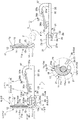
しかして本実施形態では図7〜図9に示すように、ナス環3に対して下方向、横方向並びに上方向の何れの方向に荷重が加わった場合でも連結部材2に予め設定された強度に対応した荷重を超えると外れるようになっている。同図では、ナス環3に掛かる荷重がそれぞれ下方向、横方向並びに上方向に掛かった場合の動作を模式的に示している。なお本実施形態では連結部材2の上端部21は両側が取付部材11の規制縁17に拘束されて取付部材11は連結部材2に対し取付軸15の軸芯の延出方向にずれることはない。また取付部材11の下端部22の両側はナス環3の側縁34近傍に設定されるため、ナス環3は、連結部材2に対して上記の延出方向にずれることはない。それ故本実施形態ではナス環3に加わる荷重がいずれの方向であっても以下に記す首振り方向すなわち図示上下方向の回転動作へと変換される。
Therefore, in this embodiment, as shown in FIGS. 7 to 9, the strength set in advance in the connecting
具体的に説明すると、図7に矢印に示すようにナス環3に対し上から下方向の荷重が掛かったとき、同図並びに図1、図2及び図3に示す状態から連結部材2はなんら動作を行うことなく荷重を受ける。このときの荷重は、上端部21、下端部22及び垂下壁24すなわち連結部材本体が専ら受けることになる。一方薄肉変形部23は下端部22に片持ち支持されており先端は上端部21に対し隙間2sを隔てて形成された自由端となっているので、当該荷重になんら関係が無い。
More specifically, when a downward load is applied to the
そして、図7右側にて示すように、矢印で示した荷重が一定の値を超えると本実施形態では上端部21が変形することにより、取付部材11と連結部材2との接続が解除され、ナス環3が鞄本体1から離脱する。上記一定の値とは、連結部材2を構成する素材や厚み寸法やその他具体的形状を適宜設定される。本実施形態では例えば鞄本体1を背負っている就学児童の姿勢が崩されてしまうような荷重が掛かると同図のようにナス環3が鞄本体1から離脱する。
Then, as shown on the right side of FIG. 7, when the load indicated by the arrow exceeds a certain value, the
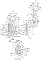
そして図8では、矢印に示すようにナス環3に対し横方向の荷重が掛かった状態を示している。同図に示すように、連結部材2は、ナス環3に掛かる荷重方向に応じて、取付部材11に対し首振動作を行う。換言すれば、取付部材11の取付軸15を中心とした回転動作を行なうことにより、連結部材2が荷重方向に沿った向きへと姿勢変更を行う。当該首振動作により、ナス環3と連結部材2との相対位置は図7に示す状態と殆ど変化が無い。そして本実施形態では、取付部材11の取付軸15を断面略真円形状に形成するとともに上端部21の摺接面を略真円形状に設定し、上端部21を構成する樹脂素材の厚み寸法を上端部21の略全域に亘って同じとなるように設定している。これにより、首振動作によって図7に示す状態とは、取付部材11及び連結部材2の相対位置は異なるものの、互いに接している箇所及びその周辺の形状が図7に示す態様、特に図7のA部拡大断面図及び図8のB部拡大断面図に示すように、略同じとなっている。これにより、図8に示すような荷重が掛かっても、図7に示すときと略同じ荷重により連結部材2が変形し、ナス環3が鞄本体1から離脱する。
FIG. 8 shows a state in which a lateral load is applied to the
さらに図9では、矢印に示すようにナス環3に対し下から上方向の荷重が掛かった状態をしめしている。同図に示すように、連結部材2は図8同様、取付部材11の取付軸15を中心とした回転動作を行なうことにより、連結部材2が荷重方向に沿った向きへと姿勢変更を行う。当該首振動作により、ナス環3と連結部材2との相対位置は図7及び図8に示す状態と殆ど変化が無い。そして本実施形態では上述同様に、取付軸15の形状並びに上端部21の形状により、首振動作によって図7及び図8に示す状態とは、取付部材11及び連結部材2の相対位置は異なるものの、互いに接している箇所及びその周辺の形状が図7並びに図8示す態様、特に図7のA部拡大断面図及び図8のB部拡大断面図に示すように、図9のC部拡大断面図においても略同じとなっている。これにより、図9に示すような荷重が掛かっても、図7及び図8に示すときと略同じ荷重により連結部材2が変形し、ナス環3が鞄本体1から離脱する。
Further, FIG. 9 shows a state in which an upward load is applied to the
すなわち本実施形態の吊下具5によれば、ナス環3への荷重が、下方向、垂直方向、上方向の何れの方向に加わった場合でも同じ荷重で外れる。また、この連結部材2は鞄本体1に固定されていないため、樹脂素材の強度が低下した場合でも、容易に交換が可能である。
That is, according to the
以上のような構成とすることにより、本実施形態に係る吊下具5は、鞄本体1に設けられた取付部材11に支持されるフック体たるナス環3と、このナス環3と取付部材11との間に介設されナス環3に作用する荷重に応じて首振り動作を行う連結部材2とを具備してなり、連結部材2が、ナス環3に一定以上の引張り荷重が作用した場合に変形し又は破壊されてナス環3を取付部材11に対して離脱させるように強度が設定されている。これにより、連結部材2が荷重の方向に応じて首振動作可能に構成されているため、荷重を受ける連結部材2の姿勢が荷重の方向によって変化してしまうことが抑制される。これにより、荷重の方向が変わっても連結部材2に対し予め設定された強度に応じた荷重でナス環3を離脱させることができる。加えて本実施形態によれば、一度ナス環3を離脱させて連結部材2が変形してしまっても、連結部材2のみを交換すればよい。これにより、当該連結部材2を取り替えることでフック体たるナス環3が外れた後でも再度外れる前と同じ状態に容易に復元させ得るものとなっている。すなわち、リベット10による固定を解除するような専用の工具を用いる大掛かりな修理を強いられる取付部材11の交換を行うことなく継続して使用できる。
With the above-described configuration, the hanging
連結部材2の強度設定を容易且つ正確に行い得るようにするために本実施形態では、連結部材2を、変形可能な樹脂製の、具体的にはナイロン製の一体成形されたものとしている。
In this embodiment, the connecting
そしてナス環3の着脱を容易なものとしつつ当該ナス環3の着脱を繰り返しても荷重によりナス環3を離脱させるときの荷重の値に影響を及ぼさないようにし得る態様として本実施形態では、連結部材2が、取付部材11に掛けられる上端部21及びナス環3に係わり合う下端部22を備えた一部に開口を有した輪状の連結部材本体21、22、24と、この連結部材2の開口たる隙間2sに臨設され当該開口を取付部材11又はナス環3が通過するときに他の部位よりも優先して変形可能に設けられた先端が開放端である片持ち薄肉部たる薄肉辺形部とを備えたものである態様としている。特に薄肉変形部23の先端を開放端としているので、繰り返しナス環3を着脱して当該薄肉変形部23のみの強度に変化を来したとしても、荷重に対応する上端部21、下端部22を離間させる外力には当該薄肉変形部23の箇所の強度は何ら関係が無いので、薄肉変形部23によるナス環3の着脱及び取付部材11に対する着脱の容易さと設定された強度の安定した維持とを両立せしめている。
In the present embodiment, as an aspect that makes it easy to attach and detach the
加えて本実施形態では、連結部材2を、上端部21の幅寸法を下端部22の幅寸法よりも大きく設定し、下端部22に掛けられるナス環3が上端部21側に移動し得ないようにすることで、常に取付部材11とナス環3とが常に両端に位置することで変形し易い姿勢となることを有効に回避している。
In addition, in this embodiment, the connecting
特に本実施形態では、連結部材2の形状を、取付部材11並びにナス環3の幅寸法に応じつつ、可能な限りできるだけ幅広に設定している。これにより、樹脂素材の厚み寸法の設定が、変形を起こす離脱荷重値に比例し易く且つ個体間のばらつきを低減し、当該離脱荷重値の正確さを有効に向上せしめている。併せて連結部材2の形状を幅広に設定することにより、取付部材11と連結部材2との間のがたつきも、連結部材2とナス環3との間のがたつきも無くしている。
In particular, in this embodiment, the shape of the connecting
加えて本実施形態では、吊下対象物の取付を就学児童でも容易に行い得るように構成するため、数あるフック体の中の一例として、輪の一部が開閉し、吊下対象物を押し込むことにより連結可能に構成されたナス環3を採用している。
In addition, in this embodiment, since it is configured so that the suspended object can be easily attached even to school children, as an example of a number of hook bodies, a part of the ring is opened and closed, and the suspended object is An
また本実施形態では、鞄本体1を、外側面に取付部材11を備えたランドセルとした態様としているが、上述の通りナス環3たるナス環3に掛かる下方向、横方向、上方向の何れの方向に加わった場合でも同じ荷重で外れるようにして、ナス環3への外力によって就学児童が姿勢を崩してしまうといった現象が生ずる可能性を有効に排除している。
Moreover, in this embodiment, although the bag
また、ナス環3に加わる荷重を安定して連結部材2に伝達させるべく本実施形態では、取付部材11が、外面にリベット10を用いて強固に止着された態様としている。
Further, in the present embodiment, the mounting
また取付部材11及び鞄本体1の強度の維持と、連結部材2の安定した首振動作とを両立させるために本実施形態では、取付部材11を、線材を環状に成形し基端部側をプレスにより扁平に成形した外面に密着するプレス領域11aと、線材自体の断面形状を維持しながら外面から離間するように成形した線状領域11bとを有するものとしている。
Moreover, in order to make the maintenance of the intensity | strength of the
そして連結部材2の首振動作を円滑に行わせ得る取付部材11の具体的な態様として本実施形態では、記線状領域11bの先端で連結部材2を支持するとともに連結部材2が線状領域11bと外面との間のスペース11cを利用して首振動作する態様を適用している。
In the present embodiment, as a specific aspect of the
特に本実施形態では上記スペース11cの寸法を連結部材2の上端部21の厚み寸法よりも大きく設定しているので、連結部材2の首振動作が鞄本体1側の構成になんら干渉されることはなく、荷重の方向に応じたスムーズな首振動作を実現している。
In particular, in the present embodiment, the dimension of the
以上、本発明の実施形態について説明したが、各部の具体的な構成は、上述した実施形態のみに限定されるものではなく、本発明の趣旨を逸脱しない範囲で種々変形が可能である。 Although the embodiment of the present invention has been described above, the specific configuration of each unit is not limited to the above-described embodiment, and various modifications can be made without departing from the spirit of the present invention.
例えば、上記実施形態では取付部材がリベットに対して強固に固定されている態様を開示したが、勿論、取付部材がリベットを軸としてマチの面方向に沿って回動可能としたものであってもよい。また上記実施形態では連結部材の上端部が下端部に優先して変形することによりフック体を離脱させる態様を開示したが勿論、下端部を上端部に優先して変形する態様であっても良い。この場合、片持ち薄肉部は上端部側に片持ち支持させ、下端部との間に隙間たる開口を形成することが好ましい。さらに、フック体や鞄本体の具体的な態様は上記実施形態のものに限定されることはなく、既存のものを含め、種々の態様のものを適用することができる。 For example, in the above-described embodiment, a mode in which the mounting member is firmly fixed to the rivet has been disclosed. Of course, the mounting member can be rotated along the gusset surface direction with the rivet as an axis. Also good. Moreover, although the aspect which makes a hook body detach | leave by disclosing the upper end part of a connection member preferentially to a lower end part was disclosed in the said embodiment, of course, the aspect which preferentially deforms a lower end part to an upper end part may be sufficient. . In this case, it is preferable that the cantilevered thin portion is cantilevered on the upper end side to form an opening between the lower end portion. Furthermore, specific modes of the hook body and the bag main body are not limited to those of the above-described embodiment, and various modes including existing ones can be applied.
その他、各部の具体的構成についても上記実施形態に限られるものではなく、本発明の趣旨を逸脱しない範囲で種々変形が可能である。 In addition, the specific configuration of each part is not limited to the above embodiment, and various modifications can be made without departing from the spirit of the present invention.
本発明は吊下対象物を吊り下げるための吊下具及び当該吊下具を具備する鞄として利用することができる。 INDUSTRIAL APPLICABILITY The present invention can be used as a suspending tool for suspending a suspended object and a ridge provided with the suspending tool.
1…鞄本体
10…リベット
11…取付部材
11a…プレス領域
11b…線状領域
11c…スペース
15…取付軸
16…持出杆
2…連結部材
2a…巾広領域
2b…巾狭領域
2c…禁止面
21…上端部
22…下端部
23…片持ち薄肉部(薄肉変形部)
3…フック体(ナス環)
5…吊下具
DESCRIPTION OF
3. Hook body (eggplant ring)
5 ... Hanging tool
Claims (9)
前記連結部材が、前記フック体に作用する荷重の方向に応じて首振り動作を行うように構成されるとともに前記フック体に一定以上の引張り荷重が作用した場合に変形し又は破壊されて前記フック体を前記取付部材に対して離脱させるように強度設定されたものである吊下具。 A connecting member that is hooked to an attaching member provided on the main body, and a hook body that is attached to the attaching member via the connecting member;
The connecting member is configured to swing in accordance with the direction of the load acting on the hook body, and is deformed or broken when a certain tensile load is applied to the hook body. A hanging tool whose strength is set so that the body is detached from the mounting member.
Priority Applications (1)
| Application Number | Priority Date | Filing Date | Title |
|---|---|---|---|
| JP2015123599A JP6816349B2 (en) | 2015-06-19 | 2015-06-19 | Hanging tools and bags |
Applications Claiming Priority (1)
| Application Number | Priority Date | Filing Date | Title |
|---|---|---|---|
| JP2015123599A JP6816349B2 (en) | 2015-06-19 | 2015-06-19 | Hanging tools and bags |
Publications (2)
| Publication Number | Publication Date |
|---|---|
| JP2017006292A true JP2017006292A (en) | 2017-01-12 |
| JP6816349B2 JP6816349B2 (en) | 2021-01-20 |
Family
ID=57762095
Family Applications (1)
| Application Number | Title | Priority Date | Filing Date |
|---|---|---|---|
| JP2015123599A Active JP6816349B2 (en) | 2015-06-19 | 2015-06-19 | Hanging tools and bags |
Country Status (1)
| Country | Link |
|---|---|
| JP (1) | JP6816349B2 (en) |
Citations (10)
| Publication number | Priority date | Publication date | Assignee | Title |
|---|---|---|---|---|
| JPS5168705U (en) * | 1974-11-26 | 1976-05-31 | ||
| JPS52159804U (en) * | 1976-05-27 | 1977-12-05 | ||
| JPS5679188U (en) * | 1979-11-20 | 1981-06-26 | ||
| US4700761A (en) * | 1986-07-24 | 1987-10-20 | Samuel Gladding | Swag bag |
| US5429288A (en) * | 1991-12-12 | 1995-07-04 | Sattler; Warren A. | Supplemental carry strap |
| JPH0951845A (en) * | 1995-08-17 | 1997-02-25 | Ikedaya Kabanten:Kk | Bag hook for satchel or the like |
| JPH09220112A (en) * | 1996-02-19 | 1997-08-26 | Hashimoto:Kk | Eggplant ring for bag |
| JP2006006713A (en) * | 2004-06-28 | 2006-01-12 | Seiban:Kk | school bag |
| US20070294863A1 (en) * | 2006-06-27 | 2007-12-27 | Rivet International, Inc. | Apparatus for Fastening |
| JP3166249U (en) * | 2010-12-14 | 2011-02-24 | ナース鞄工株式会社 | School bag suspension |
-
2015
- 2015-06-19 JP JP2015123599A patent/JP6816349B2/en active Active
Patent Citations (10)
| Publication number | Priority date | Publication date | Assignee | Title |
|---|---|---|---|---|
| JPS5168705U (en) * | 1974-11-26 | 1976-05-31 | ||
| JPS52159804U (en) * | 1976-05-27 | 1977-12-05 | ||
| JPS5679188U (en) * | 1979-11-20 | 1981-06-26 | ||
| US4700761A (en) * | 1986-07-24 | 1987-10-20 | Samuel Gladding | Swag bag |
| US5429288A (en) * | 1991-12-12 | 1995-07-04 | Sattler; Warren A. | Supplemental carry strap |
| JPH0951845A (en) * | 1995-08-17 | 1997-02-25 | Ikedaya Kabanten:Kk | Bag hook for satchel or the like |
| JPH09220112A (en) * | 1996-02-19 | 1997-08-26 | Hashimoto:Kk | Eggplant ring for bag |
| JP2006006713A (en) * | 2004-06-28 | 2006-01-12 | Seiban:Kk | school bag |
| US20070294863A1 (en) * | 2006-06-27 | 2007-12-27 | Rivet International, Inc. | Apparatus for Fastening |
| JP3166249U (en) * | 2010-12-14 | 2011-02-24 | ナース鞄工株式会社 | School bag suspension |
Also Published As
| Publication number | Publication date |
|---|---|
| JP6816349B2 (en) | 2021-01-20 |
Similar Documents
| Publication | Publication Date | Title |
|---|---|---|
| JP3116255U (en) | Eggplant ring and key holder using the same | |
| JP2017006292A (en) | Suspension tool and kite | |
| US7140585B2 (en) | One-hand clip capable of preventing hanging object from dropping | |
| JP3172052U (en) | School bag suspension | |
| JP2012153419A (en) | Container holder | |
| JP3203790U (en) | Hanging member and school bag | |
| JP5820949B1 (en) | school bag | |
| JP4025131B2 (en) | strap | |
| JP2016112170A (en) | Satchel | |
| JP3062285U (en) | Hanger for bottle container | |
| JP3113296U (en) | Suspension belt strap for backpack | |
| JP2001008722A (en) | Hanger | |
| JP3143578U (en) | Drink holder | |
| JP4968725B2 (en) | Strap aid | |
| JP7483258B2 (en) | Hanging device for small items in bags | |
| JP3212535U (en) | Eggplant | |
| JP2006103727A (en) | Portable bottle holder | |
| JP6441752B2 (en) | Ring, hanger, and hanger | |
| JP5916926B1 (en) | bag | |
| JP4746937B2 (en) | Suspension fixing member for long body | |
| JP3108502U (en) | strap | |
| JP3163440U (en) | Portable umbrella hanging | |
| US806476A (en) | Attachable receptacle for vehicle-bodies. | |
| JP3206639U (en) | Container holder | |
| JP3105377U (en) | Supplies for portable supplies |
Legal Events
| Date | Code | Title | Description |
|---|---|---|---|
| A621 | Written request for application examination |
Free format text: JAPANESE INTERMEDIATE CODE: A621 Effective date: 20180518 |
|
| A977 | Report on retrieval |
Free format text: JAPANESE INTERMEDIATE CODE: A971007 Effective date: 20190404 |
|
| A131 | Notification of reasons for refusal |
Free format text: JAPANESE INTERMEDIATE CODE: A131 Effective date: 20190423 |
|
| A521 | Request for written amendment filed |
Free format text: JAPANESE INTERMEDIATE CODE: A523 Effective date: 20190605 |
|
| A131 | Notification of reasons for refusal |
Free format text: JAPANESE INTERMEDIATE CODE: A131 Effective date: 20191203 |
|
| A521 | Request for written amendment filed |
Free format text: JAPANESE INTERMEDIATE CODE: A523 Effective date: 20191218 |
|
| A131 | Notification of reasons for refusal |
Free format text: JAPANESE INTERMEDIATE CODE: A131 Effective date: 20200526 |
|
| A521 | Request for written amendment filed |
Free format text: JAPANESE INTERMEDIATE CODE: A523 Effective date: 20200617 |
|
| TRDD | Decision of grant or rejection written | ||
| A01 | Written decision to grant a patent or to grant a registration (utility model) |
Free format text: JAPANESE INTERMEDIATE CODE: A01 Effective date: 20201124 |
|
| A61 | First payment of annual fees (during grant procedure) |
Free format text: JAPANESE INTERMEDIATE CODE: A61 Effective date: 20201207 |
|
| R150 | Certificate of patent or registration of utility model |
Ref document number: 6816349 Country of ref document: JP Free format text: JAPANESE INTERMEDIATE CODE: R150 |
|
| R250 | Receipt of annual fees |
Free format text: JAPANESE INTERMEDIATE CODE: R250 |
|
| R250 | Receipt of annual fees |
Free format text: JAPANESE INTERMEDIATE CODE: R250 |
|
| R250 | Receipt of annual fees |
Free format text: JAPANESE INTERMEDIATE CODE: R250 |