JP2017156558A - Manufacturing method for optical fiber cable, and manufacturing method for optical fiber tape ribbon - Google Patents
Manufacturing method for optical fiber cable, and manufacturing method for optical fiber tape ribbon Download PDFInfo
- Publication number
- JP2017156558A JP2017156558A JP2016039860A JP2016039860A JP2017156558A JP 2017156558 A JP2017156558 A JP 2017156558A JP 2016039860 A JP2016039860 A JP 2016039860A JP 2016039860 A JP2016039860 A JP 2016039860A JP 2017156558 A JP2017156558 A JP 2017156558A
- Authority
- JP
- Japan
- Prior art keywords
- optical fiber
- wide
- ribbon
- strands
- adhesive
- Prior art date
- Legal status (The legal status is an assumption and is not a legal conclusion. Google has not performed a legal analysis and makes no representation as to the accuracy of the status listed.)
- Pending
Links
Images


Abstract
【課題】 製造性に優れた光ファイバケーブルの製造方法等を提供する。【解決手段】 分割部16において切断部材25が用いられる。切断部材25は、例えばカッタなどの刃物であってもよく、板状部材、棒状部材などいずれでもよい。幅広光ファイバテープ心線13の特定の光ファイバ素線23同士の間(光ファイバ素線23の4本毎の間であって、接着部15bが形成される部位)に、切断部材25が挿入され、切断部材25で、当該光ファイバ素線23同士の間の接着剤を切断することで、幅広光ファイバテープ心線13が、複数の光ファイバテープ心線3に分割される。【選択図】図5PROBLEM TO BE SOLVED: To provide a method for manufacturing an optical fiber cable having excellent manufacturability. A cutting member 25 is used in a dividing portion 16. The cutting member 25 may be, for example, a blade such as a cutter, or may be a plate-shaped member, a rod-shaped member, or the like. The cutting member 25 is inserted between the specific optical fiber strands 23 of the wide optical fiber tape core wire 13 (between every four optical fiber strands 23 and the portion where the adhesive portion 15b is formed). By cutting the adhesive between the optical fiber strands 23 with the cutting member 25, the wide optical fiber tape core wire 13 is divided into a plurality of optical fiber tape core wires 3. [Selection diagram] FIG. 5
Description
本発明は、効率よく光ファイバケーブルおよび光ファイバテープ心線を製造することが可能な光ファイバケーブルおよび光ファイバテープ心線の製造方法に関するものである。 The present invention relates to an optical fiber cable and an optical fiber tape core manufacturing method capable of efficiently manufacturing an optical fiber cable and an optical fiber tape core.
多量のデータを高速で伝送するための光ファイバケーブルには、ケーブルへの収納や作業の簡易化のため、複数本の光ファイバ素線が並列に配置されて接着された光ファイバテープ心線が用いられている。光ファイバテープ心線としては、例えば、並列した光ファイバ素線同士が長手方向に対して、間欠的に樹脂で接着されたものが用いられている。このような光ファイバ素線同士の間欠的な接着は、集線密度の向上や曲げによる伝送ロスの低減、単心化をしやすくするなどの特徴を持つ。 An optical fiber cable for transmitting a large amount of data at high speed has an optical fiber tape core in which a plurality of optical fiber strands are arranged and bonded in parallel for easy storage and operation in the cable. It is used. As the optical fiber ribbon, for example, a fiber in which optical fiber strands arranged in parallel are intermittently bonded with a resin in the longitudinal direction is used. Such intermittent bonding of the optical fiber strands has characteristics such as an increase in the concentration density, a reduction in transmission loss due to bending, and a single core.
このような光ファイバテープ心線が複数収容された光ファイバケーブルとしては、例えば、光ファイバテープ心線を具備した光ファイバケーブルであって、光ファイバテープ心線の幅方向に隣接する樹脂部同士は光ファイバテープ心線の長手方向に互いに離れて配置され、光ファイバテープ心線を構成する単心被覆光ファイバを複数本集合したユニットを複数本撚り合わせたものを収容するケーブルコア部と、ケーブルコア部の外周に外被を具備することを特徴とする光ファイバケーブルがある(特許文献1)。 Examples of the optical fiber cable in which a plurality of such optical fiber ribbons are accommodated include, for example, an optical fiber cable having an optical fiber ribbon, and resin portions adjacent to each other in the width direction of the optical fiber ribbon. Is a cable core portion that is disposed apart from each other in the longitudinal direction of the optical fiber ribbon, and that accommodates a plurality of units in which a plurality of single-core coated optical fibers that constitute the optical fiber ribbon are gathered together; There is an optical fiber cable characterized in that a jacket is provided on the outer periphery of the cable core (Patent Document 1).
しかし、このような光ファイバケーブルを製造する際には、収容される光ファイバテープ心線が巻き付けられたボビンを設置する必要がある。特に、多数の光ファイバテープ心線を用いて光ファイバケーブルを製造する場合には、必要ボビン数が多くなり、広い製造スペースが必要となるとともに、製造準備に時間を要するという問題がある。 However, when manufacturing such an optical fiber cable, it is necessary to install a bobbin around which the optical fiber ribbon to be accommodated is wound. In particular, when an optical fiber cable is manufactured using a large number of optical fiber ribbons, there is a problem that the number of required bobbins increases, a large manufacturing space is required, and time is required for manufacturing preparation.
本発明は、このような問題に鑑みてなされたもので、製造性に優れた光ファイバケーブルの製造方法等を提供することを目的とする。 The present invention has been made in view of such problems, and an object thereof is to provide a method of manufacturing an optical fiber cable excellent in manufacturability.
前述した目的を達するために第1の発明は、光ファイバケーブルの製造方法であって、複数の光ファイバ素線が整列して形成され、隣り合う光ファイバ素線同士が接着部で接着された、幅広光ファイバテープ心線を用い、前記幅広光ファイバテープ心線を複数の光ファイバテープ心線に分割する分割工程と、分割された複数の前記光ファイバテープ心線を集合させる集合工程と、集合された前記光ファイバテープ心線の外周に外被を被覆する被覆工程と、を具備することを特徴とする光ファイバケーブルの製造方法である。 In order to achieve the above-mentioned object, the first invention is a method for manufacturing an optical fiber cable, in which a plurality of optical fiber strands are formed in alignment, and adjacent optical fiber strands are bonded to each other at a bonding portion. , Using a wide optical fiber ribbon, a dividing step of dividing the wide optical fiber ribbon into a plurality of optical fiber ribbons, an assembly step of assembling a plurality of the divided optical fiber ribbons, And a covering step of covering the outer periphery of the aggregated optical fiber ribbons with a jacket.
前記分割工程において、前記幅広光ファイバテープ心線の特定の光ファイバ素線同士の間に、切断部材を挿入し、前記切断部材で、当該光ファイバ素線同士の間の前記接着部を切断してもよい。 In the dividing step, a cutting member is inserted between specific optical fiber strands of the wide optical fiber ribbon, and the adhesive portion between the optical fiber strands is cut with the cutting member. May be.
前記幅広光ファイバテープ心線の特定の光ファイバ素線同士の間の前記接着部の接着力が他の光ファイバ素線同士の間の前記接着部の接着力よりも弱く、前記分割工程において、前記幅広光ファイバテープ心線を幅方向に広げることで、接着力の弱い特定の光ファイバ素線同士の間の前記接着部を破断してもよい。 In the dividing step, the adhesive force of the adhesive portion between specific optical fiber strands of the wide optical fiber ribbon is weaker than the adhesive force of the adhesive portion between other optical fiber strands, You may fracture | rupture the said adhesion part between specific optical fiber strands with weak adhesive force by extending the said wide optical fiber tape core wire to the width direction.
前記分割工程において、前記幅広光ファイバテープ心線の特定の光ファイバ素線同士を折り曲げ、当該光ファイバ素線同士の間の前記接着部を破断してもよい。 In the dividing step, specific optical fiber strands of the wide optical fiber ribbon may be bent, and the adhesive portion between the optical fiber strands may be broken.
前記分割工程において、前記幅広光ファイバテープ心線の特定の光ファイバ素線同士の間を境界として、前記境界で区分されるそれぞれ部位を、異なる高さの段差に接触させて、当該光ファイバ素線同士の間の前記接着部を破断してもよい。 In the dividing step, each of the portions separated by the boundary with the specific optical fiber strands of the wide optical fiber ribbon as a boundary is brought into contact with a step having a different height, and the optical fiber element is separated. You may fracture | rupture the said adhesion part between lines.
前記幅広光ファイバテープ心線の、分割される光ファイバ素線同士の間の前記接着部の接着力が、分割後の前記光ファイバテープ心線を構成する光ファイバ素線同士の間の前記接着部の接着力よりも小さいことが望ましい。 The adhesion between the optical fiber strands constituting the optical fiber tape core wire after splitting is such that the adhesive force of the adhesive portion between the optical fiber strands of the wide optical fiber ribbon is divided. It is desirable that it is smaller than the adhesive strength of the part.
前記光ファイバケーブルはスロット型光ファイバケーブルであり、前記集合工程において、中央にテンションメンバを有するスロットロッドの外周に形成された複数の溝に、前記光ファイバテープ心線を収容してもよい。 The optical fiber cable may be a slot-type optical fiber cable, and the optical fiber ribbon may be accommodated in a plurality of grooves formed on the outer periphery of a slot rod having a tension member at the center in the assembly step.
前記光ファイバケーブルはスロットレス型光ファイバケーブルであり、前記被覆工程において、前記光ファイバテープ心線の外周に、テンションメンバが埋設されるように外被を被覆してもよい。 The optical fiber cable is a slotless optical fiber cable, and in the covering step, a jacket may be covered so that a tension member is embedded on the outer periphery of the optical fiber ribbon.
前記接着部は、光ファイバ素線の長手方向に対して間欠的に配置されることが望ましい。 It is desirable that the adhesive portion is intermittently disposed with respect to the longitudinal direction of the optical fiber.
第1の発明によれば、幅広光ファイバテープ心線を用いて、これを幅方向に複数に分割して、複数の光ファイバテープ心線を得るため、製造時に光ファイバテープ心線を供給するボビン数を減らすことができる。このため、ボビンの設置スペースを削減することができるとともに、ボビンの設置作業の作業工数を削減することができるため、作業性にも優れる。 According to the first aspect of the present invention, a wide optical fiber ribbon is used and divided into a plurality of widths in the width direction to obtain a plurality of optical fiber ribbons. The number of bobbins can be reduced. For this reason, the installation space for the bobbin can be reduced, and the work man-hours for installing the bobbin can be reduced, so that the workability is excellent.
なお、切断部材を用いて、幅広光ファイバテープ心線の特定の光ファイバ素線間の接着部を切断部材で切断することで、確実に幅広光ファイバテープ心線を複数に分割することができる。 In addition, the wide optical fiber tape core can be reliably divided into a plurality of parts by cutting the bonding portion between specific optical fiber strands of the wide optical fiber ribbon using the cutting member. .
また、幅広光ファイバテープ心線の特定の光ファイバ素線同士の間の接着部の接着力を弱くしておき、幅広光ファイバテープ心線を幅方向に広げ、接着力の弱い特定の光ファイバ素線同士の間の接着部を破断することで、確実に幅広光ファイバテープ心線を複数に分割することができる。 In addition, the adhesive strength of the adhesive portion between the specific optical fiber strands of the wide optical fiber ribbon is weakened, the wide optical fiber ribbon is spread in the width direction, and the specific optical fiber having a weak adhesive strength is used. By breaking the bonding portion between the strands, the wide optical fiber ribbon can be surely divided into a plurality of pieces.
また、幅広光ファイバテープ心線の特定の光ファイバ素線同士を折り曲げ、当該光ファイバ素線同士の間の接着部を破断することで、確実に幅広光ファイバテープ心線を複数に分割することができる。 In addition, by bending the specific optical fiber strands of the wide optical fiber ribbon and breaking the adhesive portion between the optical fiber strands, the wide optical fiber ribbon is reliably divided into a plurality of pieces. Can do.
また、幅広光ファイバテープ心線の特定の光ファイバ素線同士の間を境界として、境界で区分されるそれぞれ部位を、異なる高さの段差に接触させて、当該光ファイバ素線同士の間の接着部を破断することで、確実に幅広光ファイバテープ心線を複数に分割することができる。 In addition, with specific optical fiber strands of the wide optical fiber ribbon as a boundary, each portion divided by the boundary is brought into contact with a step having a different height, so that the gap between the optical fiber strands By breaking the bonding portion, the wide optical fiber ribbon can be reliably divided into a plurality of pieces.
また、幅広光ファイバテープ心線の、分割される光ファイバ素線同士の間の接着剤の接着力を、他の光ファイバ素線同士の間の接着剤の接着力よりも小さくすることで、より確実に幅広光ファイバテープ心線を複数に分割することができる。 Also, by making the adhesive force of the adhesive between the optical fiber strands of the wide optical fiber ribbon smaller than the adhesive force of the adhesive between the other optical fiber strands, The wide optical fiber ribbon can be more reliably divided into a plurality of pieces.
また、中央にテンションメンバを有するスロットの外周に形成された複数の溝に、光ファイバテープ心線を収容することで、スロット型光ファイバケーブルを製造することができる。 Moreover, a slot-type optical fiber cable can be manufactured by accommodating an optical fiber ribbon in a plurality of grooves formed on the outer periphery of a slot having a tension member in the center.
また、光ファイバテープ心線の外周に、テンションメンバが埋設されるように外被を被覆することで、スロットレス型光ファイバケーブルを製造することができる。 Moreover, a slotless optical fiber cable can be manufactured by covering the outer periphery of the optical fiber ribbon so that the tension member is embedded.
また、接着部が、光ファイバ素線の長手方向に対して間欠的に配置されれば、光ファイバテープ心線を柔軟に変形(丸める、折りたたむ)することができ、光ファイバケーブルの細径・高密度化に有効である。 Moreover, if the bonding portion is intermittently arranged in the longitudinal direction of the optical fiber, the optical fiber ribbon can be flexibly deformed (rounded or folded), and the optical fiber cable has a small diameter / Effective for higher density.
第2の発明は、光ファイバテープ心線の製造方法であって、複数の光ファイバ素線を整列し、隣り合う光ファイバ素線同士を接着部で接着し、幅広光ファイバテープ心線を形成する接着工程と、前記幅広光ファイバテープ心線の特定の前記接着部を破断させて、複数の光ファイバテープ心線に分割する分割工程と、分割された複数の前記光ファイバテープ心線を、それぞれ巻き取る巻き取り工程と、を具備することを特徴とする光ファイバテープ心線の製造方法である。 The second invention is a method for manufacturing an optical fiber ribbon, wherein a plurality of optical fibers are aligned, and adjacent optical fibers are bonded together at an adhesive portion to form a wide optical fiber ribbon. Bonding step, splitting the specific bonding portion of the wide optical fiber ribbon, and dividing into a plurality of optical fiber ribbons, and dividing the plurality of divided optical fiber ribbons, A method of manufacturing an optical fiber ribbon, comprising: a winding step for winding each of the windings.
第2の発明によれば、複数の光ファイバテープ心線を同一の装置で一度に製造することができる。 According to the second invention, a plurality of optical fiber ribbons can be manufactured at the same time with the same apparatus.
本発明によれば、製造性に優れた光ファイバケーブルの製造方法等を提供することができる。 ADVANTAGE OF THE INVENTION According to this invention, the manufacturing method etc. of the optical fiber cable excellent in manufacturability can be provided.
以下、図面を参照しながら、本発明の実施形態について説明する。図1は、光ファイバケーブル1を示す断面図である。光ファイバケーブル1は、スロットを用いないスロットレス型光ファイバケーブルであり、複数の光ファイバテープ心線3、押さえ巻き部材7、テンションメンバ9、引き裂き紐11、外被5等から構成される。 Hereinafter, embodiments of the present invention will be described with reference to the drawings. FIG. 1 is a cross-sectional view showing an optical fiber cable 1. The optical fiber cable 1 is a slotless optical fiber cable that does not use a slot, and includes a plurality of optical fiber tape core wires 3, a presser winding member 7, a tension member 9, a tear string 11, an outer jacket 5, and the like.
光ファイバテープ心線3は、複数の光ファイバ素線が整列して形成され、隣り合う光ファイバ素線同士が接着剤で接着されたものである。なお、光ファイバテープ心線3の構成については、詳細を後述する。 The optical fiber ribbon 3 is formed by aligning a plurality of optical fiber strands and adhering adjacent optical fiber strands with an adhesive. Details of the configuration of the optical fiber ribbon 3 will be described later.
複数の光ファイバテープ心線3の外周には、押さえ巻き部材7が設けられる。押さえ巻き部材7は、縦添え巻きによって複数の光ファイバテープ心線3を一括して覆うように配置される。すなわち、押さえ巻き部材7の長手方向が光ファイバケーブル1の軸方向と略一致し、押さえ巻き部材7の幅方向が光ファイバケーブル1の周方向となるように複数の光ファイバテープ心線3の外周に縦添え巻きされる。なお、押さえ巻き部材7の外周には、図示を省略した粗巻き糸を螺旋状に巻き付けてもよい。 A presser winding member 7 is provided on the outer periphery of the plurality of optical fiber ribbons 3. The presser winding member 7 is disposed so as to collectively cover the plurality of optical fiber ribbons 3 by vertical additional winding. That is, the plurality of optical fiber ribbons 3 are arranged such that the longitudinal direction of the presser winding member 7 is substantially coincident with the axial direction of the optical fiber cable 1 and the width direction of the presser winding member 7 is the circumferential direction of the optical fiber cable 1. Wound vertically around the outer periphery. In addition, you may wind the rough winding thread | yarn which abbreviate | omitted illustration helically around the outer periphery of the pressing member 7.
押さえ巻き部材7の外周には、外被5が設けられる。外被5は、光ファイバケーブル1を被覆して保護するための層である。光ファイバケーブル1の長手方向に垂直な断面において、外被5の内部には、複数の光ファイバテープ心線3を挟んで対向する位置に一対のテンションメンバ9が設けられる。テンションメンバ9は、光ファイバケーブル1の張力を負担する。テンションメンバ9は、例えば鋼線や繊維強化プラスチックなどで構成される。 A jacket 5 is provided on the outer periphery of the presser winding member 7. The jacket 5 is a layer for covering and protecting the optical fiber cable 1. In a cross section perpendicular to the longitudinal direction of the optical fiber cable 1, a pair of tension members 9 are provided inside the jacket 5 at positions facing each other with the plurality of optical fiber ribbons 3 interposed therebetween. The tension member 9 bears the tension of the optical fiber cable 1. The tension member 9 is made of, for example, a steel wire or fiber reinforced plastic.
また、必要に応じて、テンションメンバ9の対向方向と略直交する方向に、押さえ巻き部材7を挟んで対向するように引き裂き紐11が設けられる。テンションメンバ9および引き裂き紐11は、外被5に埋設される。 Moreover, the tear string 11 is provided so that it may oppose on both sides of the press winding member 7 in the direction substantially orthogonal to the opposing direction of the tension member 9 as needed. The tension member 9 and the tear string 11 are embedded in the outer jacket 5.
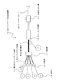
次に、光ファイバケーブル1の製造方法について説明する。図2は、光ファイバケーブル製造装置10を示す概略図である。本発明では、幅広光ファイバテープ心線13が用いられる。 Next, a method for manufacturing the optical fiber cable 1 will be described. FIG. 2 is a schematic view showing the optical fiber cable manufacturing apparatus 10. In the present invention, a wide optical fiber ribbon 13 is used.
図3は、幅広光ファイバテープ心線13を示す斜視図である。幅広光ファイバテープ心線13は、複数の光ファイバ素線23が並列に整列して形成され、隣り合う光ファイバ素線23同士が接着部で接着されて構成される。なお、光ファイバ素線23の本数は、図示した例には限られないが、使用される光ファイバテープ心線3の心数の整数倍の光ファイバ素線23から形成されることが望ましい。 FIG. 3 is a perspective view showing the wide optical fiber ribbon 13. The wide optical fiber ribbon 13 is formed by aligning a plurality of optical fiber strands 23 in parallel, and adhering adjacent optical fiber strands 23 at an adhesive portion. The number of optical fiber strands 23 is not limited to the illustrated example, but is desirably formed from optical fiber strands 23 that are an integral multiple of the number of optical fiber tape cores 3 used.
隣り合う光ファイバ素線23同士は、光ファイバ素線23の長手方向に所定の間隔をあけて間欠的に接着剤が配置される。接着剤で接着された部位を接着部15a、15bとする。すなわち、接着部15a、15bは、光ファイバ素線23の外周に設けられ、隣り合う光ファイバ素線23同士を併設して連結する。 Adjacent optical fibers 23 are adjacently disposed with a predetermined interval in the longitudinal direction of the optical fibers 23 with an adhesive disposed therebetween. The parts bonded with the adhesive are referred to as bonding parts 15a and 15b. That is, the bonding portions 15a and 15b are provided on the outer periphery of the optical fiber strand 23, and connect adjacent optical fiber strands 23 together.
隣り合う光ファイバ素線23同士の接着部15a、15bは、幅広光ファイバテープ心線13の長手方向に対して千鳥状に配置される。すなわち、図3に示すように、幅方向に隣り合う接着部15a、15bの位置が、幅広光ファイバテープ心線13の長手方向に対して互いに略半ピッチずれて、同一ピッチで形成される。 Adhering portions 15 a and 15 b between adjacent optical fiber strands 23 are arranged in a staggered manner with respect to the longitudinal direction of the wide optical fiber ribbon 13. That is, as shown in FIG. 3, the positions of the adhering portions 15 a and 15 b adjacent in the width direction are shifted from each other by about a half pitch with respect to the longitudinal direction of the wide optical fiber ribbon 13 and formed at the same pitch.
したがって、端から1本目と2本目の光ファイバ素線23同士の接着部15aは、端から3本目と4本目の光ファイバ素線23同士の接着部15aと、幅広光ファイバテープ心線13の長手方向の位置が一致し、端から1本目と2本目の光ファイバ素線23同士の接着部15aは、端から2本目と3本目の光ファイバ素線23同士の接着部15aと、幅広光ファイバテープ心線13の長手方向の位置が異なる。 Therefore, the bonding portion 15a between the first and second optical fiber strands 23 from the end is the same as the bonding portion 15a between the third and fourth optical fiber strands 23 from the end and the wide optical fiber ribbon 13. The positions 15a of the first and second optical fiber strands 23 from the end coincide with each other, and the bonded portion 15a between the second and third optical fiber strands 23 from the end is connected to the bonded portion 15a between the second and third optical fiber strands 23. The position of the fiber tape core wire 13 in the longitudinal direction is different.
なお、幅広光ファイバテープ心線13は、公知の方法(例えば、特開2013−3516号公報記載の方法)によって、製造される。 The wide optical fiber ribbon 13 is manufactured by a known method (for example, a method described in JP2013-3516A).
ここで、本実施形態では、接着部15a、15bが幅広光ファイバテープ心線13(光ファイバ素線23)の長手方向に対して間欠的に配置される例を示すが、本発明はこれに限られない。例えば、光ファイバ素線23同士を、幅広光ファイバテープ心線13の長手方向の全長にわたって形成してもよい。以下の説明では、接着部15a、15bが幅広光ファイバテープ心線13の長手方向に対して間欠的に配置される例について説明する。 Here, in this embodiment, although the adhesion parts 15a and 15b show the example arrange | positioned intermittently with respect to the longitudinal direction of the wide optical fiber tape core wire 13 (optical fiber strand 23), this invention shows this Not limited. For example, the optical fiber strands 23 may be formed over the entire length in the longitudinal direction of the wide optical fiber ribbon 13. In the following description, an example in which the bonding portions 15a and 15b are intermittently arranged in the longitudinal direction of the wide optical fiber ribbon 13 will be described.
ここで、幅広光ファイバテープ心線13の特定の光ファイバ素線23同士の間には、接着部15bが形成され、その他の光ファイバ素線23同士の間には、接着部15aが形成される。例えば、図示した例では、幅広光ファイバテープ心線13の幅方向に対して、端から1〜4本目の隣り合う光ファイバ素線23同士は、接着部15aで接着され、端から4本目と5本目の隣り合う光ファイバ素線23同士は、接着部15bで接着される。同様に、端から5〜8本目の隣り合う光ファイバ素線23同士は、接着部15aで接着され、端から8本目と9本目の隣り合う光ファイバ素線23同士は、接着部15bで接着され、端から9〜12本目の隣り合う光ファイバ素線23同士は、接着部15aで接着される。 Here, an adhesive portion 15 b is formed between specific optical fiber strands 23 of the wide optical fiber ribbon 13, and an adhesive portion 15 a is formed between other optical fiber strands 23. The For example, in the illustrated example, the adjacent optical fiber strands 1 to 4 from the end with respect to the width direction of the wide optical fiber ribbon 13 are bonded by the bonding portion 15a, and the fourth from the end. The fifth adjacent optical fiber strands 23 are bonded together by an adhesive portion 15b. Similarly, the fifth to eighth adjacent optical fiber strands 23 from the end are bonded together by the bonding portion 15a, and the eighth and ninth adjacent optical fiber strands 23 from the end are bonded by the bonding portion 15b. The 9th to 12th adjacent optical fiber strands 23 from the end are bonded together by the bonding portion 15a.
すなわち、接着部15bは、幅広光ファイバテープ心線13の幅方向に対して、所定の間隔で形成される。なお、接着部15bの形成間隔は図示した例には限られない。例えば、接着部15bは、幅広光ファイバテープ心線13の幅方向に1カ所であってもよく、2カ所以上の複数個所であってもよい。接着部15bの位置が、後述する光ファイバテープ心線への分割される部位となる。 That is, the adhesive portions 15 b are formed at a predetermined interval with respect to the width direction of the wide optical fiber ribbon 13. In addition, the formation interval of the adhesion part 15b is not restricted to the illustrated example. For example, the bonding portion 15b may be provided in one place in the width direction of the wide optical fiber ribbon 13 or may be provided in a plurality of two or more places. The position of the adhesion part 15b becomes a part to be divided into optical fiber tape cores to be described later.
接着部15bは、接着部15aよりも接着力が弱い。接着部15bの接着力を、接着部15aよりも弱くするためには、例えば、接着部15bの接着長さを、接着部15aの接着長さよりも短くするか、断面における光ファイバ素線と接着部15bとの接着面積を、接着部15aとの接着面積よりも小さくすればよい。すなわち、接着部15bの接着剤の量を、接着部15aの接着剤の量よりも少なくしておけばよい。また、接着部15bの接着剤として、接着部15aの接着剤よりも接着強度の弱いものを用いてもよい。 The adhesion part 15b has weaker adhesive force than the adhesion part 15a. In order to make the adhesive strength of the adhesive portion 15b weaker than that of the adhesive portion 15a, for example, the adhesive length of the adhesive portion 15b is made shorter than the adhesive length of the adhesive portion 15a or is bonded to the optical fiber strand in the cross section. What is necessary is just to make the adhesion area with the part 15b smaller than the adhesion area with the adhesion part 15a. That is, the amount of adhesive in the adhesive portion 15b may be set smaller than the amount of adhesive in the adhesive portion 15a. Moreover, you may use the thing whose adhesive strength is weaker than the adhesive agent of the adhesion part 15a as an adhesive agent of the adhesion part 15b.
ここで、接着強度とは、単位面積当たりの、接着剤の剥離強度を言う。すなわち、接着強度は、接着剤の種類や、光ファイバ素線23の表面性状などによって変化する。また、接着力とは、光ファイバ素線23同士を分割する際に必要な力をいう。すなわち、接着力は、接着強度×接着面積であるとする。 Here, the adhesive strength refers to the peel strength of the adhesive per unit area. That is, the adhesive strength varies depending on the type of adhesive, the surface properties of the optical fiber 23, and the like. Further, the adhesion force refers to a force required when the optical fiber strands 23 are divided. That is, the adhesive force is assumed to be adhesive strength × adhesive area.
なお、接着部15bは必ずしも必要ではなく、全てを接着部15aとしてもよい。接着部15bを用いずに、全てを接着部15aとした場合には、全ての光ファイバ素線23同士の接着力は同一となる。また、幅広光ファイバテープ心線13の長手方向の全長にわたって接着部15aを形成し、接着部15bのみ幅広光ファイバテープ心線13の長手方向に間欠的に設けてもよい。 Note that the bonding portion 15b is not necessarily required, and all may be the bonding portion 15a. When all are made into the adhesion part 15a, without using the adhesion part 15b, the adhesive force of all the optical fiber strands 23 becomes the same. Alternatively, the adhesive portion 15 a may be formed over the entire length of the wide optical fiber ribbon 13 in the longitudinal direction, and only the adhesive portion 15 b may be provided intermittently in the longitudinal direction of the wide optical fiber ribbon 13.
接着部15bの接着強度としては、0.1N以下であることが望ましい。接着部15bの接着強度が0.1N以下とすることで、後述する分割がより容易となり、分割方法の選択の幅が広がる。また、接着部15bの接着強度は、0.04N以上であることが望ましい。接着部15bの接着強度が0.04N未満であると、規定の位置での分割前に分離してしまい、分離部が工程内のガイド等に引っかかる恐れがあるためである。 The adhesive strength of the adhesive portion 15b is desirably 0.1 N or less. By setting the adhesive strength of the bonding portion 15b to 0.1 N or less, division described later becomes easier and the range of selection of the division method is expanded. Further, the adhesive strength of the adhesive portion 15b is desirably 0.04N or more. This is because if the bonding strength of the bonding portion 15b is less than 0.04N, the bonding portion 15b is separated before being divided at a specified position, and the separation portion may be caught by a guide or the like in the process.
なお、接着部15bの接着強度は、例えば以下のようにして評価することができる。図4は、接着強度測定装置40を示す図である。接着強度測定装置40は、固定部55、57、ロードセル59等から構成される。 In addition, the adhesive strength of the adhesion part 15b can be evaluated as follows, for example. FIG. 4 is a view showing the adhesive strength measuring device 40. The adhesive strength measuring device 40 includes fixed portions 55 and 57, a load cell 59, and the like.
固定部55には、環状に曲げられた針金53が固定される。針金53は例えばΦ0.5mmの鋼線である。固定部57には、あらかじめ光ファイバテープ心線から切り出された光ファイバ素線23、23の端部が固定される。光ファイバ素線23、23は、一か所の接着部15bで接着される。すなわち、一か所の接着部15bを残して光ファイバ素線23、23が所定長さに切断される。また、固定部57にはロードセル59が連結される。 A wire 53 bent in an annular shape is fixed to the fixing portion 55. The wire 53 is, for example, a steel wire having a diameter of 0.5 mm. End portions of the optical fiber strands 23 and 23 cut in advance from the optical fiber ribbon are fixed to the fixing portion 57. The optical fiber wires 23 and 23 are bonded together at one bonding portion 15b. In other words, the optical fiber strands 23 and 23 are cut to a predetermined length while leaving one adhesive portion 15b. A load cell 59 is connected to the fixed portion 57.
光ファイバ素線23、23の接着部と針金53とを引っかけた状態で、固定部55を引っ張ると、所定の荷重を付与した際に、接着部が破断する。この接着部が破断するまでの最大荷重をロードセル59で測定することで、接着部の接着強度が測定される。 If the fixing portion 55 is pulled in a state where the bonding portion of the optical fiber wires 23 and 23 and the wire 53 are hooked, the bonding portion is broken when a predetermined load is applied. By measuring the maximum load until the bonded portion breaks with the load cell 59, the bonding strength of the bonded portion is measured.
幅広光ファイバテープ心線13はボビン14に巻き付けられる。図2に示すように、光ファイバケーブル製造装置10には、複数のボビン14が配置され、それぞれのボビン14から幅広光ファイバテープ心線13が供給される(図中矢印A)。なお、ボビン14の個数は図示した例には限られない。 The wide optical fiber ribbon 13 is wound around the bobbin 14. As shown in FIG. 2, a plurality of bobbins 14 are arranged in the optical fiber cable manufacturing apparatus 10, and a wide optical fiber ribbon 13 is supplied from each bobbin 14 (arrow A in the figure). The number of bobbins 14 is not limited to the illustrated example.
ボビン14から供給された幅広光ファイバテープ心線13は、分割部16に送られる。図5は、分割部16における、幅広光ファイバテープ心線13の分割方法を示す図である。分割部16において、幅広光ファイバテープ心線13は、複数の光ファイバテープ心線3に分割される(分割工程)。例えば、12心の幅広光ファイバテープ心線13が、3本の4心の光ファイバテープ心線3に分割される。 The wide optical fiber ribbon 13 supplied from the bobbin 14 is sent to the dividing unit 16. FIG. 5 is a diagram illustrating a method of dividing the wide optical fiber ribbon 13 in the dividing unit 16. In the dividing unit 16, the wide optical fiber ribbon 13 is divided into a plurality of optical fiber ribbons 3 (dividing step). For example, a 12-core wide optical fiber ribbon 13 is divided into three 4-fiber ribbons 3.
本実施形態では、分割部16において切断部材25が用いられる。切断部材25は、例えばカッタなどの刃物であってもよく、板状部材、棒状部材などいずれでもよい。幅広光ファイバテープ心線13の特定の光ファイバ素線23同士の間(4本の光ファイバ素線23毎の間であって、接着部15bが形成される部位)に、切断部材25が挿入され、切断部材25で、当該光ファイバ素線23同士の間の接着剤を切断することで、幅広光ファイバテープ心線13が、複数の光ファイバテープ心線3に分割される(図中矢印B)。 In this embodiment, the cutting member 25 is used in the division part 16. The cutting member 25 may be a cutter such as a cutter, for example, and may be any of a plate-like member and a rod-like member. The cutting member 25 is inserted between the specific optical fiber strands 23 of the wide optical fiber ribbon 13 (the portion between the four optical fiber strands 23 and where the bonding portion 15b is formed). Then, by cutting the adhesive between the optical fiber strands 23 with the cutting member 25, the wide optical fiber ribbon 13 is divided into a plurality of optical fiber ribbons 3 (arrows in the figure). B).
なお、切断された光ファイバテープ心線3は、隣り合う光ファイバ素線23同士が、光ファイバ素線23の長手方向に所定の間隔をあけて間欠的に接着部15aで連結される。この際、隣り合う光ファイバ素線23同士の接着部15aは、光ファイバテープ心線3の長手方向に対して千鳥状に配置される。すなわち、図5に示すように、光ファイバテープ心線3の長手方向に対して、隣り合う接着部15aの位置が互いに略半ピッチずれて、同一ピッチで形成される。 In the cut optical fiber ribbon 3, adjacent optical fiber strands 23 are intermittently connected to each other at a predetermined interval in the longitudinal direction of the optical fiber strand 23 by an adhesive portion 15 a. Under the present circumstances, the adhesion part 15a of adjacent optical fiber strands 23 is arrange | positioned with respect to the longitudinal direction of the optical fiber tape core wire 3 in zigzag form. That is, as shown in FIG. 5, the positions of the adjacent adhesive portions 15 a are shifted from each other by a substantially half pitch with respect to the longitudinal direction of the optical fiber ribbon 3 and are formed at the same pitch.
図2に示すように、分割された複数の光ファイバテープ心線3は、集合部17で集合される(集合工程)。さらに、押さえ巻き部材7とともに、フォーミング装置19に送られ、集合された光ファイバテープ心線3の外周に押さえ巻き部材7が縦添え巻される。 As shown in FIG. 2, the plurality of divided optical fiber ribbons 3 are gathered at the gathering portion 17 (a gathering step). Further, the press winding member 7 is sent to the forming device 19 together with the press winding member 7, and the press winding member 7 is vertically wound around the outer periphery of the assembled optical fiber ribbon 3.
さらに、集合された光ファイバテープ心線3は、図示を省略したテンションメンバ9および引き裂き紐11とともに、外被押し出し機21に送られ、集合された光ファイバテープ心線3の外周に外被5が被覆される(被覆工程)。この際、テンションメンバ9および引き裂き紐11は外被5に埋設される。以上により、光ファイバケーブル1が製造される。なお、光ファイバケーブル1は、図示を省略したボビン等に巻き取られる。 Further, the assembled optical fiber ribbon 3 is sent to the jacket extruder 21 together with the tension member 9 and the tear string 11 (not shown), and the jacket 5 is placed on the outer periphery of the assembled optical fiber ribbon 3. Is coated (coating process). At this time, the tension member 9 and the tear string 11 are embedded in the jacket 5. Thus, the optical fiber cable 1 is manufactured. The optical fiber cable 1 is wound around a bobbin or the like (not shown).
以上、本実施の形態によれば、光ファイバケーブル製造装置10において、幅広光ファイバテープ心線13を分割して光ファイバテープ心線3とするため、必要な光ファイバテープ心線3の数だけのボビンが不要である。 As mentioned above, according to this Embodiment, in the optical fiber cable manufacturing apparatus 10, in order to divide | segment the wide optical fiber ribbon 13 into the optical fiber ribbon 3, it is only the number of required optical fiber ribbons 3. Bobbins are not required.
例えば、200心の光ファイバケーブルの場合、4心の光ファイバテープ心線が50本必要となる。したがって、従来の方法では、50本の光ファイバテープ心線を供給するための50個のボビンを設置する必要がある。これに対し、本発明では、例えば、幅広光ファイバテープ心線を3分割する場合には、その1/3の17個のボビン数で足りることとなる。このため、ボビン設置スペースを削減することができ、設置準備工数も削減することができる。 For example, in the case of a 200-fiber optical fiber cable, 50 4-fiber ribbon cables are required. Therefore, in the conventional method, it is necessary to install 50 bobbins for supplying 50 optical fiber ribbons. On the other hand, in the present invention, for example, when the wide optical fiber ribbon is divided into three, the number of 17 bobbins, which is 1/3, is sufficient. For this reason, a bobbin installation space can be reduced and an installation preparation man-hour can also be reduced.
また、分割部16では、特定の光ファイバ素線23同士の間に切断部材25を挿入し、接着部15bを切断するため、装置が簡易である。 Moreover, in the division part 16, since the cutting member 25 is inserted between specific optical fiber strands 23 and the adhesion part 15b is cut | disconnected, an apparatus is simple.
また、幅広光ファイバテープ心線13の接着部15a、15bが、幅広光ファイバテープ心線13の長手方向に間欠的に形成されるため、分断後の光ファイバテープ心線3も接着部15aが間欠的に形成される。このため、曲げや変形が容易である。 In addition, since the adhesive portions 15a and 15b of the wide optical fiber ribbon 13 are intermittently formed in the longitudinal direction of the wide optical fiber ribbon 13, the optical fiber tape core 3 after being divided also has an adhesive portion 15a. It is formed intermittently. For this reason, bending and deformation are easy.
また、接着部15bの接着強度が、接着部15aの接着強度よりも弱い。すなわち、幅広光ファイバテープ心線13の、分割される光ファイバ素線23同士の間の接着部15bの接着力が、分割後の光ファイバテープ心線3を構成する光ファイバ素線23同士の間の接着剤の接着力よりも小さい。このため、分割が容易である。特に、接着部15bの接着剤量を、接着部15aよりも少なくしておくことで、切断時に生じる接着剤のカスの発生を抑制することができる。 Further, the adhesive strength of the adhesive portion 15b is weaker than the adhesive strength of the adhesive portion 15a. That is, the adhesive force of the adhesive portion 15b between the divided optical fiber strands 23 of the wide optical fiber ribbon 13 is the same between the optical fiber strands 23 constituting the divided optical fiber ribbon 3. Less than the adhesive strength of the adhesive in between. For this reason, division is easy. In particular, by reducing the amount of adhesive in the adhesive portion 15b to be smaller than that in the adhesive portion 15a, it is possible to suppress the generation of adhesive residue generated during cutting.
次に、第2の実施形態について説明する。図6(a)は、第2の実施形態にかかる分割部16における幅広光ファイバテープ心線13の分割方法を示す図である。なお、以下の説明において、第1の実施形態と同様の機能を奏する構成については、図1〜図5と同一の符号を付し、重複する説明を省略する。 Next, a second embodiment will be described. FIG. 6A is a diagram illustrating a method of dividing the wide optical fiber ribbon 13 in the dividing unit 16 according to the second embodiment. In the following description, components having the same functions as those of the first embodiment are denoted by the same reference numerals as those in FIGS. 1 to 5, and redundant descriptions are omitted.
第2の実施形態では、分割部16において、切断部材25が用いられず、幅広光ファイバテープ心線13が幅方向に広げられる(図中矢印C)。図6(b)は、図6(a)のE部を拡大した概念図である。 In 2nd Embodiment, the cutting member 25 is not used in the division part 16, but the wide optical fiber tape core wire 13 is expanded in the width direction (arrow C in the figure). FIG. 6B is a conceptual diagram in which the E portion of FIG.
前述した様に、幅広光ファイバテープ心線13は、接着部15a、15bが、幅広光ファイバテープ心線13の長手方向に間欠に配置される。したがって、図6(b)に示すように、幅広光ファイバテープ心線13を幅方向に広げると、光ファイバ素線23同士の間隔が広くなる。 As described above, in the wide optical fiber ribbon 13, the adhesive portions 15 a and 15 b are intermittently arranged in the longitudinal direction of the wide optical fiber ribbon 13. Therefore, as shown in FIG. 6B, when the wide optical fiber ribbon 13 is expanded in the width direction, the distance between the optical fiber strands 23 is widened.
ここで、隣り合う光ファイバ素線23同士は、接着部15a、15bで接着される。この際、接着部15bは、接着部15aよりも光ファイバ素線23同士の接着力が小さい。このため、接着部15bが優先的に破断する。 Here, the adjacent optical fiber strands 23 are bonded together by bonding portions 15a and 15b. At this time, the bonding portion 15b has a smaller bonding force between the optical fiber strands 23 than the bonding portion 15a. For this reason, the adhesion part 15b breaks preferentially.
例えば、図示したように、4本の光ファイバ素線23毎に接着部15bが形成されれば、幅広光ファイバテープ心線13が4本毎に分割される。すなわち、幅広光ファイバテープ心線13から3本の4心の光ファイバテープ心線3に分割される(図6(a)の矢印D)。この際、接着部15aは破断しないため、接着部15aで間欠に接着された光ファイバテープ心線3を得ることができる。 For example, as shown in the drawing, if the bonding portion 15b is formed for each of the four optical fiber strands 23, the wide optical fiber ribbon 13 is divided into four. That is, the wide optical fiber ribbon 13 is divided into three four-fiber ribbons 3 (arrow D in FIG. 6A). At this time, since the bonded portion 15a is not broken, the optical fiber tape core wire 3 bonded intermittently by the bonded portion 15a can be obtained.
第2の実施形態によれば、第1の実施形態と同様の効果を得ることができる。また、切断部材を用いずに、容易に幅広光ファイバテープ心線13を光ファイバテープ心線3に分割することができる。 According to the second embodiment, an effect similar to that of the first embodiment can be obtained. Further, the wide optical fiber ribbon 13 can be easily divided into the optical fiber ribbon 3 without using a cutting member.
次に、第3の実施形態について説明する。図7(a)、図7(b)は、第3の実施形態にかかる分割部16における幅広光ファイバテープ心線13の分割方法を示す図である。第3の実施形態では、分割部16において、切断部材25が用いられず、幅広光ファイバテープ心線13を折り曲げることで光ファイバテープ心線3に分割する。 Next, a third embodiment will be described. FIGS. 7A and 7B are diagrams illustrating a method of dividing the wide optical fiber ribbon 13 in the dividing unit 16 according to the third embodiment. In 3rd Embodiment, in the division part 16, the cutting member 25 is not used, but it divides | segments into the optical fiber tape core wire 3 by bending the wide optical fiber tape core wire 13. FIG.
図7(b)に示すように、整列した光ファイバ素線23の端から4本目と5本目の間と、8本目と9本目の間で、光ファイバ素線23の整列方向(略直線状)に対して例えば略垂直に折り曲げることで、接着部15bを破断させることができる。以上により、幅広光ファイバテープ心線13から3本の4心の光ファイバテープ心線3に分割することができる。 As shown in FIG. 7 (b), the alignment direction (substantially linear) of the optical fiber strands 23 between the fourth and fifth ends and the eighth and ninth ends from the end of the aligned optical fiber strands 23. For example, the bonding portion 15b can be broken by bending it substantially vertically. As described above, the wide optical fiber ribbon 13 can be divided into three four-fiber ribbons 3.
なお、接着部15bの接着力が接着部15aよりも弱ければ、幅広光ファイバテープ心線13を折り曲げると、接着部15bが優先的に破断する。例えば、接着部15bの接着剤量が接着部15aの接着剤量よりも少なければ、接着部15bの折り曲げ強度が接着部15aの折り曲げ強度よりも弱くなるため、接着部15bを優先的に破断させることができる。 If the adhesive force of the adhesive portion 15b is weaker than that of the adhesive portion 15a, the adhesive portion 15b is preferentially broken when the wide optical fiber ribbon 13 is bent. For example, if the adhesive amount of the adhesive portion 15b is less than the adhesive amount of the adhesive portion 15a, the bending strength of the adhesive portion 15b becomes weaker than the bending strength of the adhesive portion 15a, so that the adhesive portion 15b is preferentially broken. be able to.
また、図示を省略した治具を用いて、接着部15aが破断せず、接着部15bの位置のみが折れ曲がるように、治具に沿って幅広光ファイバテープ心線13を折り曲げてもよい。この場合には、全ての接着部が接着部15a(同一の接着力)であってもよい。 Further, the wide optical fiber ribbon 13 may be bent along the jig so that the bonding portion 15a is not broken and only the position of the bonding portion 15b is bent using a jig not shown. In this case, all the bonded portions may be bonded portions 15a (the same bonding force).
第3の実施形態によれば、第1の実施形態と同様の効果を得ることができる。また、切断部材を用いずに、容易に幅広光ファイバテープ心線13を光ファイバテープ心線3に分割することができる。 According to the third embodiment, the same effect as that of the first embodiment can be obtained. Further, the wide optical fiber ribbon 13 can be easily divided into the optical fiber ribbon 3 without using a cutting member.
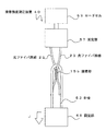
次に、第4の実施形態について説明する。図8(a)、図8(b)は、第4の実施形態にかかる分割部16における幅広光ファイバテープ心線13の分割方法を示す図である。第4の実施形態では、分割部16において、切断部材25が用いられず、ローラ27を用いて光ファイバテープ心線3に分割する。 Next, a fourth embodiment will be described. FIGS. 8A and 8B are diagrams illustrating a method of dividing the wide optical fiber ribbon 13 in the dividing unit 16 according to the fourth embodiment. In 4th Embodiment, in the division part 16, the cutting member 25 is not used, but it divides | segments into the optical fiber tape core wire 3 using the roller 27. FIG.
ローラ27には、段差29が設けられる。例えば、ローラ27の幅方向の中央部の外径(大径部27a)に対して、ローラ27の両側の外径(小径部27b)が小さい。ローラ27の中央部の大径部27aの幅は、光ファイバテープ心線3の幅とほぼ一致する。 The roller 27 is provided with a step 29. For example, the outer diameter (small diameter portion 27b) on both sides of the roller 27 is smaller than the outer diameter (large diameter portion 27a) of the central portion in the width direction of the roller 27. The width of the large-diameter portion 27 a at the center of the roller 27 substantially matches the width of the optical fiber ribbon 3.
図8(a)に示すように、幅広光ファイバテープ心線13をローラ27に対して押し付けると(図中矢印G)、幅広光ファイバテープ心線13の中央の4本の光ファイバ素線23が大径部27aと接触し、両側のそれぞれの4本の光ファイバ素線23が小径部27b上に位置する。すなわち、段差29上に接着部15bが位置する。 As shown in FIG. 8A, when the wide optical fiber ribbon 13 is pressed against the roller 27 (arrow G in the figure), the four optical fiber strands 23 at the center of the wide optical fiber ribbon 13 are formed. Is in contact with the large-diameter portion 27a, and the four optical fiber strands 23 on both sides are located on the small-diameter portion 27b. That is, the bonding portion 15 b is located on the step 29.
このため、幅広光ファイバテープ心線13をローラ27に対して押し付けると、図8(b)に示すように、段差29によって、接着部15bが破断し、光ファイバテープ心線3に分割することができる。例えば、幅広光ファイバテープ心線13から3本の4心の光ファイバテープ心線3に分割することができる。すなわち、幅広光ファイバテープ心線13の特定の光ファイバ素線23同士の間(接着部15b)を境界として、境界で区分されるそれぞれ部位を、異なる高さの段差29に接触するように押し付けることで、当該光ファイバ素線23同士の間の接着部15bを破断することができる。 For this reason, when the wide optical fiber ribbon 13 is pressed against the roller 27, the adhesive portion 15b is broken by the step 29 and is divided into the optical fiber ribbon 3 as shown in FIG. Can do. For example, the wide optical fiber ribbon 13 can be divided into three four-fiber ribbons 3. That is, with the specific optical fiber strands 23 of the wide optical fiber ribbon 13 (adhesive portion 15b) as a boundary, the respective parts divided by the boundary are pressed so as to contact the step 29 having a different height. Thereby, the adhesion part 15b between the said optical fiber strands 23 can be fractured | ruptured.
なお、段差29の位置によって、接着部15bを破断させるため、全ての接着部が接着部15a(同一の接着力)であってもよい。また、ローラ27に対する幅広光ファイバテープ心線13の位置決めを行う、ガイド等を用いてもよい。 Note that, depending on the position of the step 29, the bonding portion 15b may be broken, so that all the bonding portions may be the bonding portion 15a (the same bonding force). Further, a guide or the like for positioning the wide optical fiber ribbon 13 with respect to the roller 27 may be used.
第4の実施形態によれば、第1の実施形態と同様の効果を得ることができる。また、切断部材を用いずに、容易に幅広光ファイバテープ心線13を光ファイバテープ心線3に分割することができる。 According to the fourth embodiment, the same effect as that of the first embodiment can be obtained. Further, the wide optical fiber ribbon 13 can be easily divided into the optical fiber ribbon 3 without using a cutting member.
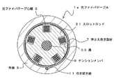
次に、スロット型の光ファイバケーブル1aについて説明する。図9は、光ファイバケーブル1aを示す断面図である。光ファイバケーブル1aは、スロットロッド31を用いたスロット型光ファイバケーブルであり、複数の光ファイバテープ心線3、押さえ巻き部材7、テンションメンバ9、引き裂き紐11、スロットロッド31、外被5等から構成される。 Next, the slot type optical fiber cable 1a will be described. FIG. 9 is a cross-sectional view showing the optical fiber cable 1a. The optical fiber cable 1a is a slot-type optical fiber cable using a slot rod 31, and includes a plurality of optical fiber ribbons 3, a presser winding member 7, a tension member 9, a tear string 11, a slot rod 31, a jacket 5, and the like. Consists of
スロットロッド31の外周部には、複数の溝33が形成される。溝33は、スロットロッド31の長手方向に連続する。なお、溝33の形状、配置数や深さは図示した例には限られない。 A plurality of grooves 33 are formed on the outer periphery of the slot rod 31. The groove 33 continues in the longitudinal direction of the slot rod 31. The shape, number of arrangements, and depth of the grooves 33 are not limited to the illustrated example.
溝33は、スロットロッド31の長手方向に対して一方向または両方向に螺旋状に形成される。したがって、スロットロッド31の長手方向に対して、各溝33の周方向位置が変化する。 The groove 33 is formed in a spiral shape in one or both directions with respect to the longitudinal direction of the slot rod 31. Therefore, the circumferential position of each groove 33 changes with respect to the longitudinal direction of the slot rod 31.
スロットロッド31の中央には、テンションメンバ9が設けられる。また、溝33内には、複数の光ファイバテープ心線3が収容される。溝33に光ファイバテープ心線3が収容された状態で、押さえ巻き部材7が巻き付けられて、引き裂き紐11とともに、外被5で被覆される。 A tension member 9 is provided at the center of the slot rod 31. A plurality of optical fiber ribbons 3 are accommodated in the groove 33. In a state where the optical fiber ribbon 3 is accommodated in the groove 33, the presser winding member 7 is wound and covered with the outer jacket 5 together with the tear string 11.
次に、光ファイバケーブル1aの製造方法について説明する。図10は、光ファイバケーブル製造装置10aを示す概略図である。なお、光ファイバケーブル製造装置10と同一の構成については、同一の符号を付し重複する説明を省略する。 Next, a method for manufacturing the optical fiber cable 1a will be described. FIG. 10 is a schematic view showing an optical fiber cable manufacturing apparatus 10a. In addition, about the structure same as the optical fiber cable manufacturing apparatus 10, the same code | symbol is attached | subjected and the overlapping description is abbreviate | omitted.
光ファイバケーブル製造装置10aには、幅広光ファイバテープ心線13が巻き付けられた複数のボビン14が配置され、それぞれのボビン14から幅広光ファイバテープ心線13が供給される(図中矢印H)。なお、ボビン14の個数は図示した例には限られない。 A plurality of bobbins 14 around which a wide optical fiber ribbon 13 is wound are disposed in the optical fiber cable manufacturing apparatus 10a, and the wide optical fiber ribbon 13 is supplied from each bobbin 14 (arrow H in the figure). . The number of bobbins 14 is not limited to the illustrated example.
ボビン14から供給された幅広光ファイバテープ心線13は、分割部16に送られる。前述したように、分割部16において、幅広光ファイバテープ心線13は、複数の光ファイバテープ心線3に分割される(分割工程)。 The wide optical fiber ribbon 13 supplied from the bobbin 14 is sent to the dividing unit 16. As described above, in the dividing unit 16, the wide optical fiber ribbon 13 is divided into a plurality of optical fiber ribbons 3 (dividing step).
次に、分割された複数の光ファイバテープ心線3は、別途供給されるテンションメンバ9が内蔵されたスロットロッド31とともに集合部17で集合される(集合工程)。集合部17では、スロットロッド31の溝33に光ファイバテープ心線3が収容される。さらに、押さえ巻き部材7とともに、フォーミング装置19に送られ、スロットロッド31の外周に押さえ巻き部材7が縦添え巻される。 Next, the plurality of divided optical fiber ribbons 3 are gathered at the gathering portion 17 together with the slot rod 31 in which the separately supplied tension member 9 is built (aggregation process). In the collecting portion 17, the optical fiber ribbon 3 is accommodated in the groove 33 of the slot rod 31. Further, it is sent to the forming device 19 together with the presser winding member 7, and the presser winding member 7 is vertically wound around the outer periphery of the slot rod 31.
さらに、集合された光ファイバテープ心線3は、図示を省略した引き裂き紐11とともに、外被押し出し機21に送られ、集合された光ファイバテープ心線3の外周に外被5が被覆される(被覆工程)。この際、引き裂き紐11は外被5に埋設される。以上により、光ファイバケーブル1aが製造される。なお、光ファイバケーブル1aは、図示を省略したボビン等に巻き取られる。 Further, the assembled optical fiber ribbon 3 is sent to the jacket extruder 21 together with the tear string 11 (not shown), and the outer circumference 5 of the assembled optical fiber ribbon 3 is covered with the jacket 5. (Coating process). At this time, the tear string 11 is embedded in the jacket 5. Thus, the optical fiber cable 1a is manufactured. The optical fiber cable 1a is wound around a bobbin or the like (not shown).
以上のように、本発明は、スロット型の光ファイバケーブル1aに対しても適用することができ、同様の効果を得ることができる。 As described above, the present invention can be applied to the slot-type optical fiber cable 1a, and the same effect can be obtained.
また、本発明は、光ファイバテープ心線の製造方法にも適用可能である。図11は、光ファイバテープ心線製造装置30を示すが略図である。光ファイバテープ心線製造装置30には、光ファイバ素線23が巻き付けられた複数のボビン34が配置される。なお、ボビン34の個数は図示した例には限られない。 The present invention is also applicable to a method for manufacturing an optical fiber ribbon. FIG. 11 is a schematic diagram showing an optical fiber ribbon manufacturing apparatus 30. In the optical fiber ribbon manufacturing apparatus 30, a plurality of bobbins 34 around which the optical fiber 23 is wound are arranged. The number of bobbins 34 is not limited to the illustrated example.
それぞれのボビン34から供給された複数の光ファイバ素線23は、集合部35で集合される(図中矢印I方向)。集合部35では、光ファイバ素線23が、一列に整列される。 The plurality of optical fiber strands 23 supplied from the respective bobbins 34 are gathered at the gathering portion 35 (in the direction of arrow I in the figure). In the assembly portion 35, the optical fiber strands 23 are aligned in a line.
集合された光ファイバ素線23は、接着部41に送られる。接着部41は、接着剤塗布部37と硬化部39とからなる。接着剤塗布部37では、整列された光ファイバ素線23の、隣り合う光ファイバ素線23同士の間に接着剤が塗布される。例えば、接着剤が光ファイバ素線23の長手方向に間欠に塗布される。接着剤は、たとえばUV樹脂である。 The assembled optical fiber strands 23 are sent to the bonding portion 41. The adhesive part 41 includes an adhesive application part 37 and a curing part 39. In the adhesive application unit 37, an adhesive is applied between the adjacent optical fiber strands 23 of the aligned optical fiber strands 23. For example, the adhesive is intermittently applied in the longitudinal direction of the optical fiber 23. The adhesive is, for example, a UV resin.
なお、接着剤塗布部37では、幅方向の特定の位置の接着剤の塗布量を、他の部位の接着剤の塗布量よりも少なくすることで、前述した接着部15bを形成することができる。 In addition, in the adhesive application part 37, the adhesive part 15b mentioned above can be formed by making the application quantity of the adhesive of the specific position of the width direction smaller than the application quantity of the adhesive of another site | part. .
硬化部39では、接着剤が硬化される。例えば、UVが照射されて、接着剤を硬化させる。以上により、隣り合う光ファイバ素線23同士が接着部で接着されて幅広光ファイバテープ心線13を形成することができる(接着工程)。 In the curing part 39, the adhesive is cured. For example, UV is irradiated to cure the adhesive. By the above, the adjacent optical fiber strands 23 can be adhere | attached by an adhesion part, and the wide optical fiber tape core wire 13 can be formed (adhesion process).
次に、幅広光ファイバテープ心線13は、分割部16に送られる。分割部16では、特定の接着部が破断されて、幅広光ファイバテープ心線13が複数の光ファイバテープ心線3に分割される(分割工程)。 Next, the wide optical fiber ribbon 13 is sent to the dividing unit 16. In the dividing portion 16, a specific adhesive portion is broken, and the wide optical fiber ribbon 13 is divided into a plurality of optical fiber ribbons 3 (dividing step).
分割された複数の光ファイバテープ心線3は、それぞれ巻き取り部43に送られて、それぞれボビンに巻き取られる(巻き取り工程)。以上により、複数の光ファイバテープ心線3を一度に製造することができる。 The plurality of divided optical fiber ribbons 3 are respectively sent to the winding unit 43 and wound around bobbins (winding step). By the above, the some optical fiber tape core wire 3 can be manufactured at once.
以上、添付図を参照しながら、本発明の実施の形態を説明したが、本発明の技術的範囲は、前述した実施の形態に左右されない。当業者であれば、特許請求の範囲に記載された技術的思想の範疇内において各種の変更例または修正例に想到し得ることは明らかであり、それらについても当然に本発明の技術的範囲に属するものと了解される。 As mentioned above, although embodiment of this invention was described referring an accompanying drawing, the technical scope of this invention is not influenced by embodiment mentioned above. It is obvious for those skilled in the art that various modifications or modifications can be conceived within the scope of the technical idea described in the claims, and these are naturally within the technical scope of the present invention. It is understood that it belongs.
1、1a………光ファイバケーブル
3………光ファイバテープ心線
5………外被
7………押さえ巻き部材
9………テンションメンバ
10、10a………光ファイバテープ心線製造装置
11………引き裂き紐
13………幅広光ファイバテープ心線
14………ボビン
15a、15b………接着部
16………分割部
17………集合部
19………フォーミング装置
21………外被押し出し機
23………光ファイバ素線
25………切断部材
27………ローラ
27a………大径部
27b………小径部
29………段差
30………光ファイバテープ心線製造装置
31………スロットロッド
33………溝
34………ボビン
35………集合部
37………接着剤塗布部
39………硬化部
40………接着強度測定装置
41………接着部
43………巻き取り部
53………針金
55、57………固定部
59………ロードセル
DESCRIPTION OF SYMBOLS 1, 1a ... Optical fiber cable 3 ... Optical fiber tape core 5 ... Outer sheath 7 ... Pressing roll member 9 ... Tension member 10, 10a ... Optical fiber tape core manufacturing apparatus 11... Tear string 13... Wide optical fiber ribbon 14... Bobbins 15 a and 15 b. ... Outer extruder 23 ......... Optical fiber 25 ......... Cutting member 27 ......... Roller 27a ......... Large diameter part 27b ......... Small diameter part 29 ......... Step 30 ......... Optical fiber tape core Wire production apparatus 31 ......... Slot rod 33 ......... Groove 34 ......... Bobbin 35 ......... Assembly part 37 ......... Adhesive application part 39 ......... Hardening part 40 ..... ... Adhesive part 43 .... Winding part 53 ... Gold 55 and 57 ......... fixed portion 59 ......... load cell
Claims (10)
複数の光ファイバ素線が整列して形成され、隣り合う光ファイバ素線同士が接着部で接着された、幅広光ファイバテープ心線を用い、
前記幅広光ファイバテープ心線を複数の光ファイバテープ心線に分割する分割工程と、
分割された複数の前記光ファイバテープ心線を集合させる集合工程と、
集合された前記光ファイバテープ心線の外周に外被を被覆する被覆工程と、
を具備することを特徴とする光ファイバケーブルの製造方法。 A method of manufacturing an optical fiber cable,
Using a wide optical fiber ribbon in which a plurality of optical fiber strands are aligned and adjacent optical fiber strands are bonded together at an adhesive portion,
A dividing step of dividing the wide optical fiber ribbon into a plurality of optical fiber ribbons;
An assembly step of assembling a plurality of the divided optical fiber ribbons;
A coating step of coating the outer periphery of the collected optical fiber ribbons;
An optical fiber cable manufacturing method comprising:
前記分割工程において、前記幅広光ファイバテープ心線を幅方向に広げることで、接着力の弱い特定の光ファイバ素線同士の間の前記接着部を破断することを特徴とする請求項1記載の光ファイバケーブルの製造方法。 The adhesive force of the adhesive portion between specific optical fiber strands of the wide optical fiber ribbon is weaker than the adhesive force of the adhesive portion between other optical fiber strands,
The said division | segmentation process WHEREIN: The said adhesion part between specific optical fiber strands with weak adhesive force is fractured | ruptured by extending the said wide optical fiber tape core wire to the width direction. Manufacturing method of optical fiber cable.
前記集合工程において、中央にテンションメンバを有するスロットロッドの外周に形成された複数の溝に、前記光ファイバテープ心線を収容することを特徴とする請求項1から請求項6のいずれかに記載の光ファイバケーブルの製造方法。 The optical fiber cable is a slot type optical fiber cable,
7. The optical fiber tape core wire is housed in a plurality of grooves formed on an outer periphery of a slot rod having a tension member at the center in the assembly step. 8. Optical fiber cable manufacturing method.
前記被覆工程において、前記光ファイバテープ心線の外周に、テンションメンバが埋設されるように外被を被覆することを特徴とする請求項1から請求項6のいずれかに記載の光ファイバケーブルの製造方法。 The optical fiber cable is a slotless optical fiber cable,
7. The optical fiber cable according to claim 1, wherein in the covering step, a jacket is covered so that a tension member is embedded in an outer periphery of the optical fiber ribbon. Production method.
複数の光ファイバ素線を整列し、隣り合う光ファイバ素線同士を接着部で接着し、幅広光ファイバテープ心線を形成する接着工程と、
前記幅広光ファイバテープ心線の特定の前記接着部を破断させて、複数の光ファイバテープ心線に分割する分割工程と、
分割された複数の前記光ファイバテープ心線を、それぞれ巻き取る巻き取り工程と、
を具備することを特徴とする光ファイバテープ心線の製造方法。 A method of manufacturing an optical fiber ribbon,
Adhering step of aligning a plurality of optical fiber strands, adhering adjacent optical fiber strands with an adhesive portion, and forming a wide optical fiber ribbon;
A splitting step of breaking the specific adhesive portion of the wide optical fiber ribbon and dividing it into a plurality of optical fiber ribbons;
A winding step of winding each of the plurality of the divided optical fiber ribbons;
The manufacturing method of the optical fiber ribbon characterized by comprising.
Priority Applications (1)
| Application Number | Priority Date | Filing Date | Title |
|---|---|---|---|
| JP2016039860A JP2017156558A (en) | 2016-03-02 | 2016-03-02 | Manufacturing method for optical fiber cable, and manufacturing method for optical fiber tape ribbon |
Applications Claiming Priority (1)
| Application Number | Priority Date | Filing Date | Title |
|---|---|---|---|
| JP2016039860A JP2017156558A (en) | 2016-03-02 | 2016-03-02 | Manufacturing method for optical fiber cable, and manufacturing method for optical fiber tape ribbon |
Publications (1)
| Publication Number | Publication Date |
|---|---|
| JP2017156558A true JP2017156558A (en) | 2017-09-07 |
Family
ID=59808766
Family Applications (1)
| Application Number | Title | Priority Date | Filing Date |
|---|---|---|---|
| JP2016039860A Pending JP2017156558A (en) | 2016-03-02 | 2016-03-02 | Manufacturing method for optical fiber cable, and manufacturing method for optical fiber tape ribbon |
Country Status (1)
| Country | Link |
|---|---|
| JP (1) | JP2017156558A (en) |
Cited By (4)
| Publication number | Priority date | Publication date | Assignee | Title |
|---|---|---|---|---|
| WO2019172444A1 (en) * | 2018-03-08 | 2019-09-12 | 古河電気工業株式会社 | Optical fiber ribbon and optical fiber cable |
| WO2019172443A1 (en) * | 2018-03-08 | 2019-09-12 | 古河電気工業株式会社 | Optical fiber ribbon and optical fiber cable |
| WO2020009116A1 (en) * | 2018-07-03 | 2020-01-09 | 日本電信電話株式会社 | Optical fiber cable, and device and method for manufacturing optical fiber cable |
| JP2020030407A (en) * | 2018-08-24 | 2020-02-27 | プリズミアン ソチエタ ペル アツィオーニ | Flexible optical fiber ribbon and manufacturing method therefor |
Citations (6)
| Publication number | Priority date | Publication date | Assignee | Title |
|---|---|---|---|---|
| US20030118301A1 (en) * | 2000-12-27 | 2003-06-26 | Hurley William C. | Fiber optic assembly and method of making same |
| JP2004061807A (en) * | 2002-07-29 | 2004-02-26 | Sumitomo Electric Ind Ltd | Single-core separating method and single-core separating jig for tape core |
| JP2005352510A (en) * | 2005-07-29 | 2005-12-22 | Sumitomo Electric Ind Ltd | Optical fiber tape unit and optical fiber cable |
| JP2014211526A (en) * | 2013-04-18 | 2014-11-13 | 日本電信電話株式会社 | Intermittent adhesion type optical fiber tape and optical cable using the same |
| JP2015004778A (en) * | 2013-06-20 | 2015-01-08 | 株式会社フジクラ | Apparatus and method for manufacturing optical fiber cable |
| CN103376521B (en) * | 2012-04-24 | 2015-06-03 | 上海裕荣光电科技股份有限公司 | Device optical fiber band and manufacturing method thereof |
-
2016
- 2016-03-02 JP JP2016039860A patent/JP2017156558A/en active Pending
Patent Citations (6)
| Publication number | Priority date | Publication date | Assignee | Title |
|---|---|---|---|---|
| US20030118301A1 (en) * | 2000-12-27 | 2003-06-26 | Hurley William C. | Fiber optic assembly and method of making same |
| JP2004061807A (en) * | 2002-07-29 | 2004-02-26 | Sumitomo Electric Ind Ltd | Single-core separating method and single-core separating jig for tape core |
| JP2005352510A (en) * | 2005-07-29 | 2005-12-22 | Sumitomo Electric Ind Ltd | Optical fiber tape unit and optical fiber cable |
| CN103376521B (en) * | 2012-04-24 | 2015-06-03 | 上海裕荣光电科技股份有限公司 | Device optical fiber band and manufacturing method thereof |
| JP2014211526A (en) * | 2013-04-18 | 2014-11-13 | 日本電信電話株式会社 | Intermittent adhesion type optical fiber tape and optical cable using the same |
| JP2015004778A (en) * | 2013-06-20 | 2015-01-08 | 株式会社フジクラ | Apparatus and method for manufacturing optical fiber cable |
Cited By (14)
| Publication number | Priority date | Publication date | Assignee | Title |
|---|---|---|---|---|
| US11105992B2 (en) | 2018-03-08 | 2021-08-31 | Furukawa Electric Co., Ltd. | Optical fiber ribbon and optical fiber cable |
| WO2019172443A1 (en) * | 2018-03-08 | 2019-09-12 | 古河電気工業株式会社 | Optical fiber ribbon and optical fiber cable |
| JPWO2019172443A1 (en) * | 2018-03-08 | 2021-02-18 | 古河電気工業株式会社 | Optical fiber tape core wire and optical fiber cable |
| CN111868592A (en) * | 2018-03-08 | 2020-10-30 | 古河电气工业株式会社 | Fiber optic ribbon and fiber optic cable |
| WO2019172444A1 (en) * | 2018-03-08 | 2019-09-12 | 古河電気工業株式会社 | Optical fiber ribbon and optical fiber cable |
| CN111837064A (en) * | 2018-03-08 | 2020-10-27 | 古河电气工业株式会社 | Fiber optic ribbon and fiber optic cable |
| JPWO2019172444A1 (en) * | 2018-03-08 | 2021-03-11 | 古河電気工業株式会社 | Optical fiber tape core wire and optical fiber cable |
| JP7288429B2 (en) | 2018-03-08 | 2023-06-07 | 古河電気工業株式会社 | Optical fiber ribbon and optical fiber cable |
| JP7025099B2 (en) | 2018-07-03 | 2022-02-24 | 日本電信電話株式会社 | Optical fiber cable and optical fiber cable manufacturing equipment and manufacturing method |
| JP2020008612A (en) * | 2018-07-03 | 2020-01-16 | 日本電信電話株式会社 | Optical fiber cable, and apparatus and method for manufacturing optical fiber cable |
| US11360281B2 (en) | 2018-07-03 | 2022-06-14 | Nippon Telegraph And Telephone Corporation | Optical fiber cable, and device and method for manufacturing optical fiber cable |
| WO2020009116A1 (en) * | 2018-07-03 | 2020-01-09 | 日本電信電話株式会社 | Optical fiber cable, and device and method for manufacturing optical fiber cable |
| JP2020030407A (en) * | 2018-08-24 | 2020-02-27 | プリズミアン ソチエタ ペル アツィオーニ | Flexible optical fiber ribbon and manufacturing method therefor |
| JP7474034B2 (en) | 2018-08-24 | 2024-04-24 | プリズミアン ソチエタ ペル アツィオーニ | Optical fiber cable and method for manufacturing an optical fiber cable |
Similar Documents
| Publication | Publication Date | Title |
|---|---|---|
| EP3553578B1 (en) | Intermittent connection type optical fiber tape core, method for manufacturing same, optical fiber cable, and optical fiber cord | |
| JP4055000B2 (en) | Optical fiber cable, optical fiber cable manufacturing method, and optical fiber cable manufacturing apparatus | |
| JP5224403B2 (en) | Optical fiber unit and optical fiber cable | |
| JP6639773B2 (en) | Loose tube optical fiber unit | |
| JP5697011B2 (en) | Optical fiber cable and method of forming optical fiber cable | |
| JP2011232733A (en) | Coated optical fiber ribbon, optical fiber cable and manufacturing method for coated optical fiber ribbon | |
| JP2017156558A (en) | Manufacturing method for optical fiber cable, and manufacturing method for optical fiber tape ribbon | |
| EP3705924A1 (en) | Optical fiber unit and optical fiber cable | |
| JP2020024257A (en) | Optical fiber ribbon, optical fiber cable, and fusion connection method of optical fiber ribbon | |
| EP3660566B1 (en) | Optical fiber ribbon and optical fiber cable | |
| JP6373196B2 (en) | Fiber optic cable | |
| JP2014137480A (en) | Optical fiber cable | |
| CN114641717A (en) | Optical cable and method for manufacturing optical cable | |
| JP6391508B2 (en) | Optical fiber ribbon | |
| JP5823247B2 (en) | Optical fiber unit, optical fiber unit manufacturing method, optical fiber cable | |
| JP6462507B2 (en) | Optical fiber cable and optical fiber cable manufacturing method | |
| KR20200106570A (en) | Optical fiber unit and optical fiber cable | |
| JP6329912B2 (en) | Optical fiber ribbon, optical fiber cable | |
| JP7479225B2 (en) | Optical fiber ribbon, optical fiber cable | |
| US11435543B2 (en) | Optical fiber unit and optical fiber cable | |
| JP2001318286A (en) | Optical fiber cable and combined power / optical cable | |
| JP7732801B2 (en) | Intermittently adhesive optical fiber ribbon, optical fiber cable | |
| JP6534953B2 (en) | Optical fiber ribbon, method of separating optical fiber ribbon | |
| JP2005128423A (en) | Optical fiber cable and manufacturing method thereof | |
| JP2021189231A (en) | Coated optical fiber, optical fiber ribbon, and optical fiber cable |
Legal Events
| Date | Code | Title | Description |
|---|---|---|---|
| A621 | Written request for application examination |
Free format text: JAPANESE INTERMEDIATE CODE: A621 Effective date: 20190110 |
|
| A131 | Notification of reasons for refusal |
Free format text: JAPANESE INTERMEDIATE CODE: A131 Effective date: 20191119 |
|
| A977 | Report on retrieval |
Free format text: JAPANESE INTERMEDIATE CODE: A971007 Effective date: 20191120 |
|
| A02 | Decision of refusal |
Free format text: JAPANESE INTERMEDIATE CODE: A02 Effective date: 20200602 |