JP2017193991A - Engine state parameter calculating device, engine control system, and engine state parameter calculating method - Google Patents
Engine state parameter calculating device, engine control system, and engine state parameter calculating method Download PDFInfo
- Publication number
- JP2017193991A JP2017193991A JP2016083899A JP2016083899A JP2017193991A JP 2017193991 A JP2017193991 A JP 2017193991A JP 2016083899 A JP2016083899 A JP 2016083899A JP 2016083899 A JP2016083899 A JP 2016083899A JP 2017193991 A JP2017193991 A JP 2017193991A
- Authority
- JP
- Japan
- Prior art keywords
- time point
- engine
- sensor output
- calculation unit
- time
- Prior art date
- Legal status (The legal status is an assumption and is not a legal conclusion. Google has not performed a legal analysis and makes no representation as to the accuracy of the status listed.)
- Pending
Links
Images


Landscapes
- Testing Of Engines (AREA)
- Combined Controls Of Internal Combustion Engines (AREA)
Abstract
【課題】 クランク角度センサのセンサ出力に基づくエンジン状態パラメータの算出精度を高めること。【解決手段】 エンジン状態パラメータ算出装置は、エンジンのクランクシャフトに対して設けられるクランク角度センサのセンサ出力の複数時点でのサンプリング値を取得する取得部と、センサ出力が上昇又は下降する区間内の2時点でのサンプリング値に基づいて、センサ出力が所定基準値となる時点である基準時点を算出する基準時点算出部と、基準時点算出部により算出される基準時点に基づいて、エンジンの状態を表すパラメータを算出するパラメータ算出部とを含む。【選択図】図7PROBLEM TO BE SOLVED: To improve calculation accuracy of an engine state parameter based on a sensor output of a crank angle sensor. An engine state parameter calculation device includes an acquisition unit that acquires sampling values of a sensor output of a crank angle sensor provided for a crankshaft of an engine at a plurality of time points, and a section within a section where the sensor output rises or falls. Based on the sampling values at the two time points, a reference time point calculation unit that calculates a reference time point when the sensor output becomes a predetermined reference value, and a state of the engine based on the reference time point calculated by the reference time point calculation unit. And a parameter calculation unit that calculates a parameter to be expressed. [Selection diagram] Fig. 7
Description
本開示は、エンジン状態パラメータ算出装置、エンジン制御システム及びエンジン状態パラメータ算出方法に関する。 The present disclosure relates to an engine condition parameter calculation device, an engine control system, and an engine condition parameter calculation method.
クランク角度センサのクランク角信号の立ち上がりエッジの時間間隔を計測することでエンジン回転数(クランク角速度と等価のエンジン状態パラメータ)を算出する技術が知られている。 A technique for calculating an engine speed (an engine state parameter equivalent to a crank angular speed) by measuring a time interval between rising edges of a crank angle signal of a crank angle sensor is known.
しかしながら、クランク角度センサのセンサ出力をサンプリングする際のサンプリングレートの限界等に起因して、クランク角信号の立ち上がりエッジを精度良く生成することは難しい。従って、従来技術では、クランク角速度のような、エンジンの状態を表すパラメータの算出精度を高めることが難しい。 However, it is difficult to accurately generate the rising edge of the crank angle signal due to the limit of the sampling rate when sampling the sensor output of the crank angle sensor. Therefore, it is difficult for the prior art to increase the calculation accuracy of a parameter representing the state of the engine, such as the crank angular speed.
そこで、1つの側面では、本発明は、クランク角度センサのセンサ出力に基づくエンジン状態パラメータの算出精度を高めることを目的とする。 Accordingly, in one aspect, an object of the present invention is to improve calculation accuracy of an engine state parameter based on a sensor output of a crank angle sensor.
一局面によれば、エンジンのクランクシャフトに対して設けられるクランク角度センサのセンサ出力の複数時点でのサンプリング値を取得する取得部と、
前記センサ出力が上昇又は下降する区間内の2時点での前記サンプリング値に基づいて、前記センサ出力が所定基準値となる時点である基準時点を算出する基準時点算出部と、
前記基準時点算出部により算出される基準時点に基づいて、エンジンの状態を表すパラメータを算出するパラメータ算出部とを含む、エンジン状態パラメータ算出装置が提供される。
According to one aspect, an acquisition unit that acquires sampling values at a plurality of time points of a sensor output of a crank angle sensor provided for a crankshaft of an engine;
A reference time point calculation unit that calculates a reference time point that is a time point at which the sensor output becomes a predetermined reference value based on the sampling values at two time points within a section in which the sensor output increases or decreases;
There is provided an engine condition parameter calculation device including a parameter calculation unit that calculates a parameter representing the state of the engine based on the reference time point calculated by the reference time point calculation unit.
クランク角度センサのセンサ出力に基づくエンジン状態パラメータの算出精度を高めることが可能となる。 It becomes possible to improve the calculation accuracy of the engine condition parameter based on the sensor output of the crank angle sensor.
以下、添付図面を参照しながら各実施例について詳細に説明する。 Hereinafter, embodiments will be described in detail with reference to the accompanying drawings.
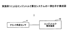
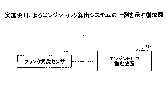
図1は、実施例1によるエンジントルク算出システム1の一例を示す構成図である。
FIG. 1 is a configuration diagram illustrating an example of an engine
エンジントルク算出システム1は、エンジン(図示せず)を備える車両に搭載される。車両は、エンジンのみを駆動源とする車両であってもよいし、電気モータとエンジンの双方を駆動源とするハイブリッド車であってもよい。エンジンの種類は任意であり、例えば、ガソリンエンジンであってもよいし、ディーゼルエンジンであってもよい。
The engine
エンジントルク算出システム1は、クランク角度センサ4と、エンジントルク算出装置10を含む。
The engine
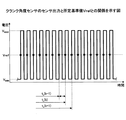
クランク角度センサ4は、エンジンに取り付けられる。クランク角度センサ4は、エンジンのクランクシャフト6(図2参照)の回転角度であるクランク角度を表すセンサ出力を生成する。例えば、クランク角度センサ4は、クランクシャフトに固定されるクランクロータ(シグナルロータ)5と協動して、センサ出力を生成する。クランクロータ5は、図2及び図3に示すように、外周に、所定クランク角ピッチ角Δθ(例えば6CAピッチ)(以下、「ピッチ角Δθ」と称する)に対応したピッチで突起(歯)5bを有しつつ、上死点検出用に欠歯部5aを有してもよい。尚、"CA"とはクランク角を表す。
実施例1では、一例として、クランク角度センサ4は、磁気抵抗素子を含むMRE(magneto resistive effect)センサである。図4は、クランクロータ5の外周の形状特徴とクランク角度センサ4のセンサ出力との関係の説明図である。図4には、上側には、クランクロータ5の外周を直線状に展開した状態が示され、下側には、上側に図示するクランクロータ5の外周の形状特徴に対応したクランク角度センサ4のセンサ出力が示されている。図5は、クランク角度センサ4のセンサ出力と所定基準値(判定基準電圧)との関係を示す図である。
The
In the first embodiment, as an example, the
クランクロータ5が回転すると、クランクロータ5の歯5bがクランク角度センサ4に近づいたり離れたりすることを繰り返す。クランク角度センサ4は、クランクロータ5の歯5bによる磁界変化を検知することで、クランクロータ5の歯5bの有無に応じて、パルス状の信号を出力する。このとき、パルス状の信号のピッチθ2がクランクロータ5のピッチ角Δθに相当する。
When the
クランク角度センサ4がクランクロータ5の欠歯部5aに対向する区間では、磁界変化が起こらないため、センサ出力も変化しない。即ち、クランク角度センサ4は、クランクロータ5の欠歯部5aに対向する間は、クランクロータ5が角度θ1だけ回転する時間分、新たな立ち上がりパルスを出力しない。角度θ1は、(欠歯本数+1)×Δθに相当する。以下、センサ出力における欠歯部5aに起因した区間(角度θ1分の区間)を、「欠歯区間」と称する。
In the section where the
センサ出力は、クランク角度センサ4がクランクロータ5の欠歯部5a以外に対向する区間では、図5に示すように、クランクシャフトの回転に伴い周期的に所定基準値Vrefをクロスする。具体的には、センサ出力は、クランクシャフトの回転に伴いピッチ角Δθ毎に所定基準値を上下に計2回クロスする。このように、センサ出力は、クランク角度0〜720CAの区間において、クランクシャフトの回転に伴いピッチ角Δθ毎に所定基準値を上下に計2回クロスする区間と、上死点検出用の欠歯区間とを含む。以下、クランクシャフトの回転に伴いピッチ角Δθ毎に所定基準値Vrefを上下に計2回クロスする区間を、「非欠歯区間」とも称する。尚、非欠歯区間においては、センサ出力が0Vを負から正の方向(上り)にクロスする毎に(図5の○印参照)、クランク角度がピッチ角Δθ分だけ進角することになる。実施例1では、一例として、センサ出力は、所定基準値Vrefを基準とした振幅が一定であるものとする。即ち、図5に示すように、センサ出力は、固定の最大電圧VMAXと固定の最少電圧VMINとの間を周期的に上下し、所定基準値Vref=(VMAX+VMIN)/2である。
As shown in FIG. 5, the sensor output periodically crosses the predetermined reference value Vref as the crankshaft rotates in a section where the
図6は、エンジントルク算出装置10のハードウェア構成の一例を示す図である。エンジントルク算出装置10のハードウェアは、例えば、マイクロコンピューターや、FPGA(Field Programmable Gate Array)、PLC(Programmable Logic Controller)等を含んでよい。
FIG. 6 is a diagram illustrating an example of a hardware configuration of the engine
図6に示す例では、エンジントルク算出装置10は、制御部101、主記憶部102、補助記憶部103、及び、ハードウェアI/F部106を含む。
In the example illustrated in FIG. 6, the engine
制御部101は、主記憶部102や補助記憶部103に記憶されたプログラムを実行する演算装置であり、記憶装置からデータを受け取り、演算、加工した上で、記憶装置などに出力する。制御部101は、例えばCPU(Central Processing Unit)やタイマカウンタ等を含んでよい。
The
主記憶部102は、ROM(Read Only Memory)やRAM(Random Access Memory)などであり、制御部101が実行するアプリケーションソフトウェアなどのプログラムやデータを記憶又は一時保存する記憶装置である。
The
補助記憶部103は、EEPROM(Electric-Erasable Programmable Read-Only Memory)などであり、アプリケーションソフトウェアなどに関連するデータを記憶する記憶装置である。
The
ハードウェアI/F部106は、有線及び/又は無線回線などで接続された車両ネットワーク(例えば、CAN(Controller Area Network)等)やエンジンの周辺機器(例えば、クランク角度センサ4等)とのインターフェースである。
The hardware I /
図7は、実施例1によるエンジントルク算出装置10の機能ブロック図である。エンジントルク算出装置10は、A/Dコンバータ(Analog-to-Digital)110と、サンプル値取得部111(取得部の一例)と、サンプル値記憶部114とを含む。また、エンジントルク算出装置10は、クロス時点算出部120(基準時点算出部の一例)と、クランク角度算出部121と、クロス時点記憶部122とを含む。また、エンジントルク算出装置10は、クランク角速度算出部123と、クランク角速度記憶部124と、クランク角加速度算出部130と、エンジントルク算出部160(パラメータ算出部の一例)とを含む。各部111、120、121、123、130、及び160は、制御部101が主記憶部102内のプログラムを実行することにより実現できる。また、サンプル値記憶部114、クロス時点記憶部122、及びクランク角速度記憶部124は、例えば主記憶部102のRAMにより実現できる。
FIG. 7 is a functional block diagram of the engine
A/Dコンバータ110は、クランク角度センサ4のセンサ出力に係るアナログ入力を量子化出力に変換する。
The A / D converter 110 converts an analog input related to the sensor output of the
サンプル値取得部111は、A/Dコンバータ110を介して、クランク角度センサ4のセンサ出力の複数時点でのサンプリング値を取得する。例えば、サンプル値取得部111は、A/Dコンバータ110を介して、所定のサンプリングレートでセンサ出力をサンプリングする。所定のサンプリングレートは、後述の上り区間内で少なくとも2時点以上でのサンプリング値が取得できるように設定される。所定のサンプリングレートは、一定であってもよいし、例えばエンジン回転数等に応じて可変であってもよい。サンプル値取得部111は、取得したサンプリング値をサンプル値記憶部114に記憶する。
The sample value acquisition unit 111 acquires sampling values at a plurality of points in time of the sensor output of the
サンプル値記憶部114は、サンプル値取得部111により取得されたサンプリング値を記憶する記憶領域を有する。記憶領域は、例えば最新の所定数以上のサンプリング値を記憶する容量を備える。サンプル値記憶部114は、例えばリングバッファであり、最新の所定数以上のサンプリング値を、FIFO(first-in, first-out)形式で保持する。所定数は、クロス時点算出部120で用いられるサンプリング値の数以上であり、例えば2である。 The sample value storage unit 114 has a storage area for storing the sampling values acquired by the sample value acquisition unit 111. The storage area has a capacity for storing, for example, the latest predetermined number or more of sampling values. The sample value storage unit 114 is, for example, a ring buffer, and holds the latest predetermined number or more of sampling values in a FIFO (first-in, first-out) format. The predetermined number is equal to or greater than the number of sampling values used in the cross point calculation unit 120, and is two, for example.
クロス時点算出部120は、センサ出力が上昇する区間(以下、「上り区間」とも称する」内の2時点でのサンプリング値に基づいて、センサ出力が所定基準値Vrefとなる時点を算出する。上り区間とは、センサ出力が、最少電圧VMINから立ち上がり始めた以後であって最大電圧VMAXに至る以前の区間を指す。 The cross time calculation unit 120 calculates a time point at which the sensor output becomes the predetermined reference value Vref based on sampling values at two time points in a section where the sensor output increases (hereinafter also referred to as “upward section”). The section refers to a section after the sensor output starts rising from the minimum voltage VMIN and before reaching the maximum voltage VMAX .
実施例1では、一例として、クロス時点算出部120は、センサ出力の上り区間内の、所定基準値Vrefを挟む2時点でのサンプリング値に基づいて、センサ出力が所定基準値Vrefをクロスする時点(以下、「クロス時点」とも称する)を算出する。例えば、クロス時点算出部120は、サンプル値記憶部114に直近に記憶されるサンプリング値が、所定基準値Vref未満である状態から所定基準値Vrefを超えたときに、サンプル値記憶部114内の直近の2時点のサンプリング値を取り出す。そして、クロス時点算出部120は、取り出した2時点のサンプリング値に基づいて、クロス時点を算出する。クロス時点算出部120は、算出したクロス時点をクロス時点記憶部122に記憶する。 In the first embodiment, as an example, the cross time point calculation unit 120 is a time point at which the sensor output crosses the predetermined reference value Vref based on sampling values at two time points sandwiching the predetermined reference value Vref in the upstream section of the sensor output. (Hereinafter also referred to as “cross point”). For example, when the sampling value stored most recently in the sample value storage unit 114 exceeds the predetermined reference value Vref from a state where it is less than the predetermined reference value Vref, the cross time calculation unit 120 stores the value in the sample value storage unit 114. The sampling values at the two most recent time points are taken out. Then, the cross time point calculation unit 120 calculates the cross time point based on the extracted sampling values at the two time points. The cross time point calculation unit 120 stores the calculated cross time point in the cross time point storage unit 122.
図8は、クロス時点算出部120によるクロス時点の算出方法の説明図である。図8には、横軸に時間を取り、縦軸に電圧を取り、センサ出力の波形70が示されている。図8には、サンプリング周期i(=n−3〜n+2)で得られたサンプリング点s(n−3)〜s(n+2)が○印で示される。尚、サンプリング点(及び後述のクロス点)とは、電圧情報と時間情報とで2次元位置(図8に示すような2軸の座標系内での位置)が定まる点に対応する。
FIG. 8 is an explanatory diagram of a cross time calculation method performed by the cross time calculation unit 120. In FIG. 8, time is plotted on the horizontal axis and voltage is plotted on the vertical axis, and a
図8に示す例では、所定基準値Vrefを挟む2時点でのサンプリング値は、サンプリング点s(n−1)での電圧値v(n−1)及びサンプリング点s(n)での電圧値v(n)である。また、2時点は、時点t(n−1)及び時点t(n)であり、時点tcがクロス時点である。尚、時点とは、時間軸上の1点であり、時間とは、時間軸上の長さを表す。以下では、一例として、時点t(n−1)、時点t(n)、及びクロス時点tcは、共通の開始時点(例えば図8の時間軸の原点に相当するタイミング)からの時間でそれぞれで表される。 In the example shown in FIG. 8, the sampling values at two time points across the predetermined reference value Vref are the voltage value v (n−1) at the sampling point s (n−1) and the voltage value at the sampling point s (n). v (n). The two time points are time point t (n-1) and time point t (n), and time point tc is a cross time point. The time point is one point on the time axis, and the time represents a length on the time axis. In the following, as an example, the time point t (n-1), the time point t (n), and the cross time point tc are respectively times from a common start time point (for example, timing corresponding to the origin of the time axis in FIG. 8). expressed.
具体的には、クロス時点算出部120は、2時点でのサンプリング値間の差分ΔVと、2時点間の時間dtとに基づいて、2時点間でのセンサ出力の時間変化率βを算出する。図8では、2時点でのサンプリング値間の差分は、ΔVであり、ΔV=v(n)−v(n−1)である。2時点間の時間dtは、サンプリングレートに対応する。従って、2時点間でのセンサ出力の時間変化率βは、β=ΔV/dt=(v(n)−v(n−1))/dtである。そして、クロス時点算出部120は、算出した時間変化率βに基づいて、クロス時点tcを算出する。例えば、クロス時点tcは、時点t(n−1)を基準として、以下の通り算出できる。
tc=(Vref−v(n−1))/β+t(n−1)
或いは、クロス時点tcは、時点t(n)を基準として、以下の通り算出できる。
tc=t(n)−(v(n)−Vref)/β
この算出方法は、センサ出力が、図8に示すように、最大電圧VMAX及び最少電圧VMIN間で線形的に変化する場合に好適である。換言すると、この算出方法は、センサ出力が最大電圧VMAX及び最少電圧VMIN間で一定の時間変化率で変化すると仮定して、センサ出力が所定基準値Vrefとなるクロス点Pc(図8参照)を求めるものである。従って、クロス時点tcに係るクロス点Pcは、サンプリング点s(n−1)とサンプリング点s(n)とを結んだ直線(傾きはβ)と、所定基準値Vrefを表す直線(傾きは0)との交点である。
Specifically, the cross time calculation unit 120 calculates the time change rate β of the sensor output between the two time points based on the difference ΔV between the sampling values at the two time points and the time dt between the two time points. . In FIG. 8, the difference between the sampling values at two time points is ΔV, and ΔV = v (n) −v (n−1). The time dt between the two time points corresponds to the sampling rate. Therefore, the time change rate β of the sensor output between the two time points is β = ΔV / dt = (v (n) −v (n−1)) / dt. Then, the cross time point calculation unit 120 calculates the cross time point tc based on the calculated time change rate β. For example, the cross time point tc can be calculated as follows using the time point t (n−1) as a reference.
tc = (Vref−v (n−1)) / β + t (n−1)
Alternatively, the cross time tc can be calculated as follows with respect to the time t (n).
tc = t (n) − (v (n) −Vref) / β
This calculation method is suitable when the sensor output changes linearly between the maximum voltage V MAX and the minimum voltage V MIN as shown in FIG. In other words, this calculation method assumes that the sensor output changes at a constant time change rate between the maximum voltage V MAX and the minimum voltage V MIN , and the cross point Pc at which the sensor output becomes the predetermined reference value Vref (see FIG. 8). ). Therefore, the cross point Pc related to the cross time point tc is a straight line (slope is β) connecting the sampling point s (n−1) and the sampling point s (n), and a straight line representing the predetermined reference value Vref (slope is 0). ).
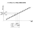
クランク角度算出部121は、クロス時点算出部120により算出されたクロス時点に基づいて、クロス時点でのクランク角度を算出する。実施例1では、一例として、クロス時点は、図9に示すように、クランク角度がピッチ角Δθ分だけ進角するタイミングとされる。従って、今回のクロス時点でのクランク角度は、前回のクロス時点でのクランク角度に対してピッチ角Δθ分を加算することで算出できる。図9には、3つの連続した算出周期(k−1、k、k+1)で算出される各クランク角度CA(k−1)、CA(k)、及びCA(k+1)が示される。tc(k−1)、tc(k)、及びtc(k+1)は、それぞれ、各算出周期(k−1、k、k+1)に係るクロス時点tcである。尚、時間軸上で隣接する2つのクロス時点間の時間は、クランク角速度に応じて異なる。例えば、算出周期k−1に係るクロス時点tc(k−1)と算出周期kに係るクロス時点tc(k)との間の時間Δt(k−1)は、算出周期kに係るクロス時点tc(k)と算出周期k+1に係るクロス時点tc(k+1)との間の時間Δt(k)とは異なり得る。尚、欠歯区間においては、クランク角度算出部121は、ピッチ角Δθに代えて、角度θ1(図4参照)だけ進角させることで、クランク角度を算出してよい。 The crank angle calculation unit 121 calculates a crank angle at the cross time based on the cross time calculated by the cross time calculation unit 120. In the first embodiment, as an example, as shown in FIG. 9, the cross time point is the timing at which the crank angle is advanced by the pitch angle Δθ. Therefore, the crank angle at the current crossing time can be calculated by adding the pitch angle Δθ to the crank angle at the previous crossing time. FIG. 9 shows the crank angles CA (k−1), CA (k), and CA (k + 1) calculated in three consecutive calculation cycles (k−1, k, k + 1). tc (k−1), tc (k), and tc (k + 1) are cross time points tc related to the respective calculation periods (k−1, k, k + 1). Note that the time between two crossing points adjacent on the time axis varies depending on the crank angular velocity. For example, the time Δt (k−1) between the cross time tc (k−1) related to the calculation cycle k−1 and the cross time tc (k) related to the calculation cycle k is equal to the cross time tc related to the calculation cycle k. The time Δt (k) between (k) and the cross time point tc (k + 1) related to the calculation cycle k + 1 may be different. In the missing tooth section, the crank angle calculation unit 121 may calculate the crank angle by advancing the angle θ1 (see FIG. 4) instead of the pitch angle Δθ.
クロス時点記憶部122は、クロス時点算出部120により算出されたクロス時点を記憶する記憶領域を有する。記憶領域は、例えば最新の所定数以上のクロス時点を記憶する容量を備える。クロス時点記憶部122は、例えばリングバッファであり、最新の所定数以上のクロス時点を、FIFO形式で保持する。所定数は、クランク角速度算出部123やクランク角加速度算出部130での算出方法に依存するが、例えば2である。 The cross time storage unit 122 includes a storage area for storing the cross time calculated by the cross time calculation unit 120. The storage area has a capacity for storing, for example, the latest predetermined number or more of cross points. The cross point storage unit 122 is, for example, a ring buffer, and holds the latest predetermined number of cross points or more in the FIFO format. The predetermined number is, for example, 2 although it depends on the calculation method in the crank angular velocity calculation unit 123 and the crank angular acceleration calculation unit 130.
クランク角速度算出部123は、クロス時点算出部120により算出されたクロス時点に基づいて、クランク角速度を算出する。具体的には、クランク角速度算出部123は、非欠歯区間において、時間軸上で隣接する2つのクロス時点間の時間と、ピッチ角Δθとに基づいて、クランク角速度を算出する。即ち、算出周期kにおけるクランク角速度ω(k)は、例えば以下のとおりである。 The crank angular velocity calculation unit 123 calculates the crank angular velocity based on the cross time calculated by the cross time calculation unit 120. Specifically, the crank angular velocity calculation unit 123 calculates the crank angular velocity based on the time between two cross points adjacent on the time axis and the pitch angle Δθ in the non-missing tooth section. That is, the crank angular velocity ω (k) in the calculation cycle k is, for example, as follows.
クランク角速度算出部123は、例えばクロス時点算出部120により新たなクロス時点が算出される毎に、クロス時点記憶部122から直近の2つのクロス時点(今回新たに算出されたクロス時点を含む)を取り出す。そして、クランク角速度算出部123は、取り出した直近の2つのクロス時点と、ピッチ角Δθ(既知)とに基づいて、クランク角速度を算出し、算出したクランク角速度をクランク角速度記憶部124に記憶する。 For example, every time a new cross time is calculated by the cross time calculation unit 120, the crank angular velocity calculation unit 123 calculates the two most recent cross time points (including the newly calculated cross time point) from the cross time storage unit 122. Take out. Then, the crank angular speed calculation unit 123 calculates a crank angular speed based on the last two cross points taken out and the pitch angle Δθ (known), and stores the calculated crank angular speed in the crank angular speed storage unit 124.
クランク角速度記憶部124は、クランク角速度算出部123により算出されたクランク角速度を記憶する記憶領域を有する。記憶領域は、例えば最新の所定数以上の算出周期分のクランク角速度を記憶する容量を備える。クランク角速度記憶部124は、例えばリングバッファであり、最新の所定数以上の算出周期分のクランク角速度を、FIFO形式で保持する。所定数は、クランク角加速度算出部130のクランク角加速度算出処理に必要な算出周期分の数以上であり、クランク角加速度算出方法に依存する。例えば、クランク角加速度算出部130が直近の2時点のクランク角速度に基づいてクランク角加速度を算出する場合は、所定数は、例えば2である。 The crank angular speed storage unit 124 has a storage area for storing the crank angular speed calculated by the crank angular speed calculation unit 123. The storage area has a capacity for storing, for example, the latest crank angular speeds for a predetermined number of calculation cycles or more. The crank angular velocity storage unit 124 is, for example, a ring buffer, and holds the crank angular velocity for the latest predetermined number of calculation cycles or more in a FIFO format. The predetermined number is equal to or greater than the number of calculation cycles necessary for the crank angular acceleration calculation process of the crank angular acceleration calculation unit 130, and depends on the crank angular acceleration calculation method. For example, when the crank angular acceleration calculation unit 130 calculates the crank angular acceleration based on the crank angular velocities at the two most recent time points, the predetermined number is, for example, two.
クランク角加速度算出部130は、クランク角速度算出部123より算出されたクランク角速度に基づいて、クランク角加速度を算出する。例えば、クランク角加速度算出部130は、クランク角速度算出部123により新たなクランク角速度が算出される毎に、クランク角速度記憶部124から直近の2算出周期分のクランク角速度と、クロス時点記憶部122から直近の2つのクロス時点とを取り出す。そして、クランク角加速度算出部130は、取り出した直近の2算出周期分のクランク角速度と、直近の2つのクロス時点とに基づいて、クランク角加速度を算出する(図10参照)。算出周期kにおけるクランク角加速度α(k)は、例えば以下の通り算出できる。 The crank angular acceleration calculation unit 130 calculates the crank angular acceleration based on the crank angular velocity calculated by the crank angular velocity calculation unit 123. For example, every time a new crank angular velocity is calculated by the crank angular velocity calculating unit 123, the crank angular acceleration calculating unit 130 calculates the crank angular velocity for the two latest calculation cycles from the crank angular velocity storage unit 124 and the cross time point storage unit 122. Take the last two cross points. Then, the crank angular acceleration calculation unit 130 calculates the crank angular acceleration based on the extracted crank angular speeds for the two most recent calculation cycles and the two most recent cross points (see FIG. 10). The crank angular acceleration α (k) in the calculation cycle k can be calculated as follows, for example.
エンジントルク算出部160は、クランク角加速度算出部130により算出されたクランク角加速度に基づいて、エンジントルクを算出する。実施例1では、一例として、エンジントルク算出部160は、図示トルクを算出する。算出周期kにおける図示トルクτ(k)は、例えば以下の通り算出できる。 The engine torque calculation unit 160 calculates engine torque based on the crank angular acceleration calculated by the crank angular acceleration calculation unit 130. In the first embodiment, as an example, the engine torque calculation unit 160 calculates the indicated torque. The indicated torque τ (k) in the calculation cycle k can be calculated as follows, for example.
次に、図11乃至図13を参照して、比較例と対比しつつ、上述した実施例1による効果を説明する。 Next, with reference to FIG. 11 to FIG. 13, effects of the above-described first embodiment will be described in comparison with the comparative example.
図11は、2算出周期でそれぞれ算出されるクロス時点の例を示す図である。図11には、算出周期k−1に係るクロス時点tc(k−1)と、算出周期kに係るクロス時点tc(k)とが示される。 FIG. 11 is a diagram illustrating an example of cross points calculated in two calculation cycles. FIG. 11 shows a cross time point tc (k−1) related to the calculation cycle k−1 and a cross time point tc (k) related to the calculation cycle k.
算出周期k−1では、図11の左側に示すように、所定基準値Vrefを挟む2時点でのサンプリング値は、サンプリング点s(m−1)での電圧値v(m−1)及びサンプリング点s(m)での電圧値v(m)である。また、2時点は、時点t(m−1)及び時点t(m)である。従って、算出周期k−1に係るクロス時点tc(k−1)は、上述のように次のとおりである。
tc(k−1)=(Vref−v(m−1))/β(k−1)+t(m−1)
但し、β(k−1)=(v(m)−v(m−1))/dt
算出周期kでは、図11の右側に示すように、所定基準値Vrefを挟む2時点でのサンプリング値は、サンプリング点s(n−1)での電圧値v(n−1)及びサンプリング点s(n)での電圧値v(n)である。また、2時点は、時点t(n−1)及び時点t(n)である。従って、算出周期kに係るクロス時点tc(k)は、上述のように次のとおりである。
tc(k)=(Vref−v(n−1))/β(k)+t(n−1)
但し、β(k)=(v(n)−v(n−1))/dt
ここで、次の比較例を想定する。比較例では、所定基準値Vrefよりも大きいサンプリング値がサンプリングされた時点が、「クロス時点」として扱われる。従って、比較例では、算出周期kにおけるクランク角速度ω(k)は、以下のとおりである。
In the calculation cycle k−1, as shown on the left side of FIG. 11, the sampling values at two time points sandwiching the predetermined reference value Vref are the voltage value v (m−1) and sampling at the sampling point s (m−1). The voltage value v (m) at the point s (m). The two time points are time point t (m−1) and time point t (m). Accordingly, the cross time point tc (k−1) related to the calculation cycle k−1 is as follows as described above.
tc (k−1) = (Vref−v (m−1)) / β (k−1) + t (m−1)
Where β (k−1) = (v (m) −v (m−1)) / dt
In the calculation cycle k, as shown on the right side of FIG. 11, the sampling values at two time points across the predetermined reference value Vref are the voltage value v (n−1) and the sampling point s at the sampling point s (n−1). The voltage value v (n) at (n). The two time points are time point t (n-1) and time point t (n). Accordingly, the cross time point tc (k) related to the calculation cycle k is as follows as described above.
tc (k) = (Vref−v (n−1)) / β (k) + t (n−1)
Where β (k) = (v (n) −v (n−1)) / dt
Here, the following comparative example is assumed. In the comparative example, a time point when a sampling value larger than the predetermined reference value Vref is sampled is treated as a “cross time point”. Therefore, in the comparative example, the crank angular velocity ω (k) in the calculation cycle k is as follows.
ところで、センサ出力をサンプリングする際のサンプリングレートの限界等に起因して、クランク角度をピッチ角Δθ分だけ進角させるタイミングを、センサ出力が所定基準値Vrefをちょうどクロスする時点に正確に同期させることは難しい。換言すると、センサ出力が所定基準値Vrefとなる実際の時点を「真値」とすると、算出周期間で、真値に対するクロス時点のずれを一定にすることは難しい。例えば、真値は、実施例1によるクロス時点算出部120により算出されるクロス時点と一致するものとすると、比較例では、図11に模式的に示すように、真値に対するクロス時点のずれが、算出周期間で比較的に大きく変動しうる。具体的には、算出周期k−1での、真値に対するクロス時点のずれΔtr(k−1)と、算出周期kでの、真値に対するクロス時点のずれΔtr(k)とが有意に異なる。真値に対するクロス時点のずれが算出周期間で比較的に大きく変動するということは、実質的に、クランク角速度の算出に用いるセンサ出力の判定基準電圧が算出周期間で比較的に大きく変動していることと等価である。クランク角速度の算出に用いるセンサ出力の判定基準電圧が算出周期間で変動すると、当然ながら、クランク角速度の精度の悪化を招く。従って、比較例では、クランク角速度の算出精度を高めることが難しい。 By the way, due to the limit of the sampling rate when sampling the sensor output, the timing for advancing the crank angle by the pitch angle Δθ is accurately synchronized with the time when the sensor output just crosses the predetermined reference value Vref. It ’s difficult. In other words, if the actual time point at which the sensor output becomes the predetermined reference value Vref is “true value”, it is difficult to make the deviation of the cross time point from the true value constant during the calculation period. For example, assuming that the true value coincides with the cross time calculated by the cross time calculating unit 120 according to the first embodiment, in the comparative example, as schematically shown in FIG. , And may vary relatively greatly between calculation periods. Specifically, the deviation Δtr (k−1) of the cross time with respect to the true value in the calculation cycle k−1 is significantly different from the deviation Δtr (k) of the cross time with respect to the true value in the calculation cycle k. . The fact that the deviation of the cross point relative to the true value fluctuates relatively greatly between the calculation cycles means that the sensor output judgment reference voltage used for calculating the crank angular velocity substantially fluctuates relatively between the calculation cycles. Is equivalent to If the determination reference voltage of the sensor output used for calculation of the crank angular velocity varies between the calculation cycles, naturally, the accuracy of the crank angular velocity is deteriorated. Therefore, in the comparative example, it is difficult to increase the calculation accuracy of the crank angular velocity.
これに対して、実施例1によれば、真値に対するクロス時点(クロス時点算出部120により算出されるクロス時点)のずれが、算出周期間で比較的に大きく変動することを抑制できる。具体的には、実施例1によれば、上述のように、算出周期毎に、上り区間内の2時点でのサンプリング値に基づいて、クロス時点が算出される。クロス時点は、上述のように上り区間内の2時点間でのセンサ出力の時間変化率βに基づいて算出されるので、算出周期毎に、真値に高い精度で一致する。この結果、真値に対するクロス時点のずれが、算出周期間で比較的に大きく変動することを抑制できる。よって、実施例1によれば、比較例に比べて、クランク角速度の算出精度を高めることができる。 On the other hand, according to the first embodiment, it is possible to suppress the deviation of the cross point relative to the true value (the cross point calculated by the cross point calculator 120) from fluctuating relatively greatly between the calculation cycles. Specifically, according to the first embodiment, as described above, the cross time point is calculated on the basis of the sampling values at the two time points in the upstream section for each calculation cycle. Since the cross time is calculated based on the time change rate β of the sensor output between the two time points in the up section as described above, it coincides with the true value with high accuracy for each calculation cycle. As a result, it is possible to suppress the deviation of the crossing point from the true value from fluctuating relatively greatly between calculation cycles. Therefore, according to the first embodiment, it is possible to improve the calculation accuracy of the crank angular velocity as compared with the comparative example.
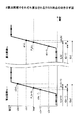
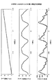
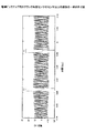
図12は、比較例による図示トルクの算出精度の説明図である。図12には、上から、センサ出力から計算されるクランク角度の時系列、クランク角速度から計算されるクランク角加速度の時系列、及びクランク角加速度から計算される図示トルクの時系列L1が示される。計算による図示トルクの時系列L1には、実測値による図示トルクの時系列L2が併せて示される。尚、実測値による図示トルクは、筒内圧センサから得られるシリンダ内の圧力変化とクランク角度変化から得られるシリンダ容積の変化を基に算出されている。図13は、実施例1による図示トルクの算出精度の説明図である。図13には、図12と同様の各時系列が示される。尚、本試験に用いたクランクロータ5の仕様は、歯の本数が60本(ピッチ角Δθ=6CA)であり、欠歯本数が4本である。エンジンの仕様は、気筒数が4個であり、クランクシャフト2回転(720CA)で全気筒が1回燃焼する。
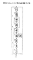
FIG. 12 is an explanatory diagram of the calculation accuracy of the indicated torque according to the comparative example. FIG. 12 shows, from above, a time series of crank angles calculated from sensor outputs, a time series of crank angular accelerations calculated from crank angular velocities, and a time series L1 of indicated torques calculated from crank angular accelerations. . The time series L1 of the indicated torque based on the calculation is shown together with the time series L2 of the indicated torque based on the actually measured value. The indicated torque based on the actually measured value is calculated based on the change in the cylinder volume obtained from the change in the cylinder pressure obtained from the in-cylinder pressure sensor and the change in the crank angle. FIG. 13 is an explanatory diagram of the calculation accuracy of the indicated torque according to the first embodiment. FIG. 13 shows each time series similar to FIG. The specification of the
比較例では、図12に示すように、実測値による図示トルクに対する算出誤差が大きい(波形が乱れている)。比較例の算出結果の根平均二乗誤差(RMSE:Root Mean Squared Error)は143.77であった。これに対して、実施例1によれば、図13に示すように、実測値による図示トルクに対する算出誤差が小さい(波形の乱れが小さくなっている)。実施例1によれば、RMSEは117.42であり、比較例に比べてRMSEを約28%低減できている。 In the comparative example, as shown in FIG. 12, the calculation error with respect to the indicated torque based on the actually measured value is large (the waveform is disturbed). The root mean squared error (RMSE) of the calculation result of the comparative example was 143.77. On the other hand, according to the first embodiment, as shown in FIG. 13, the calculation error with respect to the indicated torque based on the actually measured value is small (the disturbance of the waveform is small). According to Example 1, RMSE is 117.42, and RMSE can be reduced by about 28% compared with the comparative example.
次に、図14を参照して、エンジントルク算出装置10の動作例について説明する。
Next, an operation example of the engine
図14は、エンジントルク算出装置10により実行されるエンジントルク算出処理の一例を示すフローチャートである。図14に示す処理は、例えばサンプル値取得部111のサンプリングレート毎に実行されてよい。尚、図14に示す処理中は、エンジントルク算出装置10にはクランク角度センサ4のセンサ出力が入力され続ける。
FIG. 14 is a flowchart illustrating an example of an engine torque calculation process executed by the engine
ステップS100では、サンプル値取得部111は、センサ出力に対する今回のサンプリング周期のサンプリング値を取得し、サンプル値記憶部114に記憶する。 In step S <b> 100, the sample value acquisition unit 111 acquires the sampling value of the current sampling period with respect to the sensor output, and stores it in the sample value storage unit 114.
ステップS102では、クロス時点算出部120は、ステップS100でサンプル値取得部111が取得したサンプリング値が所定基準値Vrefを正の方向にクロスしたか否かを判定する。例えば、クロス時点算出部120は、前回のサンプリング値が所定基準値Vref未満であるが、今回のサンプリング値が所定基準値Vrefよりも大きい場合は、サンプリング値が所定基準値Vrefを正の方向にクロスしたと判定する。判定結果が"YES"の場合は、ステップS104に進み、判定結果が"NO"の場合は、今回周期の処理はそのまま終了する。 In step S102, the cross time calculation unit 120 determines whether the sampling value acquired by the sample value acquisition unit 111 in step S100 crosses the predetermined reference value Vref in the positive direction. For example, if the previous sampling value is less than the predetermined reference value Vref but the current sampling value is larger than the predetermined reference value Vref, the cross time calculation unit 120 causes the sampling value to move the predetermined reference value Vref in the positive direction. Judge that crossed. If the determination result is “YES”, the process proceeds to step S104, and if the determination result is “NO”, the processing of the current cycle is terminated as it is.
ステップS104では、クロス時点算出部120は、サンプル値記憶部114内の直近の2時点のサンプリング値を取り出し、取り出した2時点のサンプリング値に基づいて、クロス時点を算出する。クロス時点の算出方法は、上述のとおりである。クロス時点算出部120は、算出したクロス時点をクロス時点記憶部122に記憶する。 In step S104, the cross time point calculation unit 120 takes out the sampling values at the two most recent time points in the sample value storage unit 114, and calculates the cross time point based on the taken sampling values at the two time points. The calculation method of the crossing time is as described above. The cross time point calculation unit 120 stores the calculated cross time point in the cross time point storage unit 122.
ステップS106では、クランク角速度算出部123は、クロス時点記憶部122から直近の2つのクロス時点を取り出し、取り出した直近の2つのクロス時点と、ピッチ角Δθ(既知)とに基づいて、クランク角速度を算出する。クランク角速度の算出方法は、上述のとおりである。クランク角速度算出部123は、算出したクランク角速度をクランク角速度記憶部124に記憶する。 In step S106, the crank angular speed calculation unit 123 extracts the two most recent cross time points from the cross time point storage unit 122, and calculates the crank angular speed based on the two latest cross time points that have been extracted and the pitch angle Δθ (known). calculate. The method for calculating the crank angular velocity is as described above. The crank angular speed calculation unit 123 stores the calculated crank angular speed in the crank angular speed storage unit 124.
ステップS108では、クランク角加速度算出部130は、クランク角速度記憶部124内の直近の2算出周期分のクランク角速度と、クロス時点記憶部122内の直近の2つのクロス時点とに基づいて、クランク角加速度を算出する。クランク角加速度の算出方法は、上述のとおりである。 In step S108, the crank angular acceleration calculation unit 130 determines the crank angle based on the crank angular velocities for the two most recent calculation cycles in the crank angular velocity storage unit 124 and the two most recent cross points in the cross point storage unit 122. Calculate acceleration. The method for calculating the crank angular acceleration is as described above.
ステップS110では、エンジントルク算出部160は、ステップS108で算出されたクランク角加速度に基づいて、図示トルクを算出する。図示トルクの算出方法は、上述のとおりである。 In step S110, the engine torque calculation unit 160 calculates the indicated torque based on the crank angular acceleration calculated in step S108. The method for calculating the indicated torque is as described above.
このようにして図14に示す処理によれば、センサ出力が所定基準値Vrefを超える毎に(即ちクロス時点が発生する毎に)、現在の図示トルクを精度良く算出できる。このようなエンジントルク算出装置10は、リアルタイムで図示トルクを精度良く算出できるので、エンジン制御システムの高性能化に有効に利用できる。
In this way, according to the processing shown in FIG. 14, the current indicated torque can be accurately calculated every time the sensor output exceeds the predetermined reference value Vref (that is, every time the cross time occurs). Such an engine
ところで、トルクベース制御のエンジン制御システムでは、一般的にドライバーのアクセル操作などから必要な正味トルクが決まり、その正味トルクをもたらす図示トルクの目標値が設定される。このとき、実車では、車両の駆動トルクを目標値通りにフィードバック制御するために、筒内圧センサを用いて現在の図示トルクを測定することが考えられる。しかしながら、筒内圧センサの設置は、コスト、耐久性、及び保守性の問題を引き起こすことから現状困難となっている。 By the way, in an engine control system of torque-based control, generally, a necessary net torque is determined by a driver's accelerator operation or the like, and a target value of the indicated torque that provides the net torque is set. At this time, in an actual vehicle, in order to feedback control the driving torque of the vehicle according to a target value, it is conceivable to measure the current indicated torque using an in-cylinder pressure sensor. However, installation of the in-cylinder pressure sensor is currently difficult because it causes problems of cost, durability, and maintainability.
この点、実施例1によれば、筒内圧センサを設置することなく、エンジントルク算出装置10により図示トルクを高精度に算出できるので、エンジントルク算出装置10をエンジン制御システムの高性能化に有効に利用できる。
In this regard, according to the first embodiment, the indicated torque can be calculated with high accuracy by the engine
尚、実施例1では、上述したように、クロス時点算出部120は、所定基準値Vrefを挟む2時点でのサンプリング値に基づいて、クロス時点を算出するが、これに限られない。例えば、クロス時点算出部120は、所定基準値Vrefを挟む2時点でのサンプリング値に、他のサンプリング値を加えた3時点以上でのサンプリング値に基づいて、クロス時点を算出してもよい。この場合、クロス時点算出部120は、例えば最小二乗法等により、3時点以上でのサンプリング点に対する近似直線を求め、該近似直線と所定基準値Vrefを表す直線(傾き0)との交点に基づいて、クロス時点を算出してもよい。この場合、近似直線の算出に用いられる3時点以上でのサンプリング点としては、好ましくは、上り区間内のサンプリング点である。これは、最少電圧VMINから立ち上がる前のセンサ出力のサンプリング値や最大電圧VMAXに至った後のセンサ出力のサンプリング値は、センサ出力が実質的に変化していないときのサンプリング値であり、時間変化率βの算出精度を悪化させるためである。 In the first embodiment, as described above, the cross time point calculation unit 120 calculates the cross time point based on the sampling values at two time points sandwiching the predetermined reference value Vref. However, the present invention is not limited to this. For example, the cross time point calculation unit 120 may calculate the cross time point based on sampling values at three time points or more obtained by adding other sampling values to sampling values at two time points sandwiching the predetermined reference value Vref. In this case, the cross time point calculation unit 120 obtains an approximate straight line for sampling points at three or more time points by, for example, the least square method or the like, and based on the intersection of the approximate straight line and a straight line (slope 0) representing the predetermined reference value Vref. Thus, the cross time point may be calculated. In this case, the sampling points at three or more time points used for the calculation of the approximate straight line are preferably sampling points in the upstream section. This is the sampling value of the sensor output before rising from the minimum voltage V MIN and the sampling value of the sensor output after reaching the maximum voltage V MAX are the sampling values when the sensor output is not substantially changed, This is because the calculation accuracy of the time change rate β is deteriorated.
また、実施例1では、上述したように、クロス時点算出部120は、所定基準値Vrefを挟む2時点でのサンプリング値として、所定基準値Vrefを超える直前と直後の各サンプリング値を用いるが、これに限られない。例えば、クロス時点の算出に用いられる2時点でのサンプリング値は、上り区間内の2時点でのサンプリング値である限り、任意である。従って、例えば、クロス時点の算出に用いられる2時点でのサンプリング値は、センサ出力が最少電圧VMINから立ち上がった後であって所定基準値Vrefを超える前における任意の2時点でのサンプリング値であってもよい。同様に、クロス時点の算出に用いられる2時点でのサンプリング値は、センサ出力が所定基準値Vrefを超えた後であって最大電圧VMAXに至る前における任意の2時点でのサンプリング値であってもよい。 In the first embodiment, as described above, the cross time calculation unit 120 uses the sampling values immediately before and after the predetermined reference value Vref as the sampling values at the two time points sandwiching the predetermined reference value Vref. It is not limited to this. For example, the sampling values at the two time points used for the calculation of the cross time point are arbitrary as long as they are the sampling values at the two time points in the upstream section. Therefore, for example, the sampling value at two time points used for calculating the cross time point is a sampling value at any two time points after the sensor output rises from the minimum voltage V MIN and before the predetermined reference value Vref. There may be. Similarly, the sampling values at the two time points used for the calculation of the cross time point are sampling values at any two time points after the sensor output exceeds the predetermined reference value Vref and before the maximum voltage V MAX is reached. May be.
また、実施例1では、上述したように、クロス時点算出部120は、上り区間内の2時点でのサンプリング値に基づいて、クロス時点を算出するが、これに限られない。即ち、クロス時点算出部120は、センサ出力が下降する区間(以下、「下り区間」とも称する)内の2時点でのサンプリング値に基づいて、クロス時点を算出してもよい。下り区間内とは、センサ出力が、最大電圧VMAXから立ち下がり始めた以後であって最少電圧VMINに至る以前の区間を指す。例えば、クロス時点算出部120は、下り区間内の2時点でのサンプリング値であって、所定基準値Vrefを挟む2時点でのサンプリング値に基づいて、クロス時点を算出してもよい。 In the first embodiment, as described above, the cross time point calculation unit 120 calculates the cross time point based on the sampling values at the two time points in the uplink section, but is not limited thereto. That is, the cross time point calculation unit 120 may calculate the cross time point based on sampling values at two time points in a section where the sensor output decreases (hereinafter also referred to as “downward section”). The term “in the downward interval” refers to an interval after the sensor output starts falling from the maximum voltage V MAX and before reaching the minimum voltage V MIN . For example, the cross time point calculation unit 120 may calculate the cross time point based on the sampling values at the two time points in the downstream section and the sampling values at the two time points sandwiching the predetermined reference value Vref.
また、実施例1では、上述したように、所定基準値Vref=(VMAX+VMIN)/2であるが、これに限られない。例えば、所定基準値Vrefは、VMIN<Vref<VMAXの関係を満たす限り、任意である。尚、所定基準値Vref=VMAX(又はVref=VMIN)であってもよく、かかる実施例について、後述の実施例2として説明する。 In the first embodiment, as described above, the predetermined reference value Vref = (V MAX + V MIN ) / 2, but the present invention is not limited to this. For example, the predetermined reference value Vref is arbitrary as long as the relationship of V MIN <Vref <V MAX is satisfied. The predetermined reference value Vref = V MAX (or Vref = V MIN ) may be used, and this embodiment will be described as a second embodiment described later.
また、実施例1では、上述したように、クロス時点と、クランク角度がピッチ角Δθ分だけ進角するタイミングとが同じであるが、これらが同期している限り、これに限られない。例えば、クロス時点に対して固定の所定時間前又は後の時点と、クランク角度がピッチ角Δθ分だけ進角するタイミングとが同じであってもよい。 Further, in the first embodiment, as described above, the timing of the crossing and the timing at which the crank angle is advanced by the pitch angle Δθ are the same, but the present invention is not limited to this as long as they are synchronized. For example, the time point before or after a fixed predetermined time with respect to the cross time point may be the same as the timing at which the crank angle is advanced by the pitch angle Δθ.
図15は、エンジントルク算出装置10を含むエンジン制御システムの一例を示す図である。
FIG. 15 is a diagram illustrating an example of an engine control system including the engine
エンジン制御システム2は、車両に搭載される。車両は、上述のように、エンジンのみを駆動源とする車両であってもよいし、ハイブリッド車であってもよい。エンジン制御システム2は、センサ群8と、エンジン制御装置30(エンジン制御部の一例)と、エンジン80と、クランク角度センサ4と、エンジントルク算出装置10とを含む。
The
センサ群8は、クランク角度センサ4以外の各種車載センサとして、例えば、アクセル開度センサ、車速センサ、レーダセンサ、画像センサ等を含む。
The sensor group 8 includes, for example, an accelerator opening sensor, a vehicle speed sensor, a radar sensor, an image sensor, and the like as various in-vehicle sensors other than the
エンジン制御装置30は、エンジン80を電子制御する。尚、エンジン80の電子制御は、例えば、図示しないが、エンジン80の吸気マニホールド内に配置されるスロットルバルブの開度(即ち、スロットル開度)を電子制御することを含んでよい。その他、エンジン80の電子制御は、例えば、エンジン80の燃焼室に噴射される燃料の量や点火時期を電子制御することや、バルブ開閉タイミングを調整するインテークカムシャフトの位相を電子制御することを含んでよい。
The
エンジン制御装置30は、電子制御ユニット(ECU:Electronic Control Unit)により形成され、例えば図2に示したようなハードウェア構成を有してよい。エンジン制御装置30は、図15に示すように、運転者要求駆動力算出部31と、運転者支援駆動力算出部32と、目標駆動力調停部33と、フィードバック制御部34とを含む。運転者要求駆動力算出部31、運転者支援駆動力算出部32、目標駆動力調停部33、及びフィードバック制御部34は、電子制御ユニットのCPUがプログラムを実行することで実現できる。
The
運転者要求駆動力算出部31は、車速センサ及びアクセル開度センサからの情報に基づいて、車速及びアクセル開度に応じた運転者要求駆動力(以下、「第1要求駆動力」と称する)を算出する。 The driver required driving force calculation unit 31 is based on the information from the vehicle speed sensor and the accelerator opening sensor, and the driver required driving force according to the vehicle speed and the accelerator opening (hereinafter referred to as “first required driving force”). Is calculated.
運転者支援駆動力算出部32は、レーダセンサ等からの情報に基づいて、運転者による車両の運転を支援するための要求駆動力(以下、「第2要求駆動力」と称する)を算出する。第2要求駆動力は、例えば所定車速で走行するために必要な駆動力、先行車に追従するために必要な駆動力、制限車速を超えないように車速を制限するための駆動力等であってよい。
The driver support driving
目標駆動力調停部33は、所定の規則に従って、第1要求駆動力及び第2要求駆動力のいずれかを選択する。例えば、ACC(Adaptive Cruse Control)の実行中は、目標駆動力調停部33は、第1要求駆動力が0である間、第2要求駆動力を選択し、第1要求駆動力が所定閾値より大きくなると、第1要求駆動力を選択する。目標駆動力調停部33は、選択した要求駆動力を、トルク表現[N・m]に変換し、要求駆動トルクとしてフィードバック制御部34に与える。
The target driving
フィードバック制御部34は、例えば、目標駆動力調停部33から与えられる要求駆動トルクと、エンジントルク算出装置10から与えられる図示トルクの算出値との差分に基づいて、要求駆動トルクが実現されるようにエンジン80の制御目標値を決定してもよい。エンジンの制御目標値は、例えばスロットル開度の目標値や燃料の噴射量の目標値等であってよい。尚、等価的に、図示トルクの算出値に代えて、該図示トルクの算出値に基づく正味トルクの算出値が用いられてもよい。例えば、正味トルクは、図示トルクの算出値からエンジンのフリクショントルクを減算することで算出できる。また、エンジンのフリクショントルクは、例えば、エンジンの回転数および負荷に基づいて算出できる。また、フィードバック制御部34は、エンジントルク算出装置10から与えられる図示トルクの算出値に基づいて、エンジンの制御目標値として点火時期の目標値を決定してもよい。フィードバック制御部34は、決定した制御目標値が実現されるように、エンジン80を制御する。
For example, the
図15に示すエンジン制御システム2によれば、エンジントルク算出装置10を備え、要求駆動力と図示トルクの算出値との差分に基づいてエンジン80をフィードバック制御できる。上述のようにエンジントルク算出装置10からの図示トルクの算出値の算出精度が高いため、エンジン80の駆動トルクを精度良く制御できる。これにより、例えば過剰に筒内に燃料を噴射する必要がなくなり、エンジン性能が向上し、燃費やドライバビリティが改善される。このようにして、エンジントルク算出装置10をエンジン制御システムの高性能化に有効に利用できる。
According to the
尚、図15に示す例では、エンジントルク算出装置10は、エンジン制御装置30とは別に設けられるが、これに限られない。エンジントルク算出装置10の機能の一部又は全部は、エンジン制御装置30により実現されてもよい。
In the example illustrated in FIG. 15, the engine
また、図15に示す例では、エンジン制御システム2は、エンジントルク算出装置10による算出結果を用いて制御する対象は、エンジン80であるが、これに限られない。例えば、エンジントルク算出装置10による算出結果は、エンジン80以外の車両駆動装置(例えば、トランスミッション、電気モータ、クラッチ等)の制御にも用いることができる。エンジン80以外の車両駆動装置の制御目標値(例えばトランスミッションの目標ギア段)は、エンジン80の制御目標値に関連する場合があるためである。
In the example shown in FIG. 15, the
また、図15に示す例では、エンジン制御システム2は、運転者支援駆動力算出部32を備えるが、運転者支援駆動力算出部32は省略されてもよい。この場合、目標駆動力調停部33も不要となり、フィードバック制御部34は、運転者要求駆動力算出部31からの第1要求駆動力を常時用いてよい。
In the example illustrated in FIG. 15, the
[実施例2]
実施例2は、所定基準値Vrefが最大電圧VMAXである点が、上述した実施例1と異なる。実施例2によるエンジントルク算出装置10Aは、上述した実施例1によるエンジントルク算出装置10に対して、ハードウェア構成自体は同じであってよいが、機能が、以下の通り異なる。
[Example 2]
Example 2, point a predetermined reference value Vref is the maximum voltage V MAX is different from
図16は、エンジントルク算出装置10Aの機能ブロック図である。実施例2によるエンジントルク算出装置10Aは、上述した実施例1によるエンジントルク算出装置10に対して、以下の点が主に異なる。クロス時点算出部120及びクロス時点記憶部122がそれぞれ最大到達時点算出部140(基準時点算出部の一例)及び最大到達時点記憶部141で置換される。また、クランク角度算出部121、クランク角速度算出部123、及びクランク角加速度算出部130が、それぞれ、クランク角度算出部121A、クランク角速度算出部123A、及びクランク角加速度算出部130Aで置換される。他の構成要素は、上述した実施例1によるエンジントルク算出装置10と実質的に同様であってよく、図16において、同一の参照符号を付して説明を省略する。最大到達時点算出部140、クランク角度算出部121A、クランク角速度算出部123A、及びクランク角加速度算出部130Aは、制御部101が主記憶部102内のプログラムを実行することにより実現できる。また、最大到達時点記憶部141は、例えば主記憶部102のRAMにより実現できる。
FIG. 16 is a functional block diagram of the engine torque calculation device 10A. The engine torque calculation device 10A according to the second embodiment is mainly different from the engine
最大到達時点算出部140は、上り区間内の2時点でのサンプリング値に基づいて、センサ出力が所定基準値Vref(=最大電圧VMAX)となる時点である最大到達時点(立ち上がりエッジの時点)を算出する。最大到達時点算出部140は、算出した最大到達時点を最大到達時点記憶部141に記憶する。 The maximum arrival time point calculation unit 140 is based on the sampling values at the two time points in the upward section, and the maximum arrival time point (rising edge time point) when the sensor output becomes the predetermined reference value Vref (= maximum voltage V MAX ). Is calculated. The maximum arrival time calculation unit 140 stores the calculated maximum arrival time in the maximum arrival time storage unit 141.
実施例2では、一例として、最大到達時点算出部140は、上り区間内の2時点でのサンプリング値であって、中間値(=(VMAX+VMIN)/2)を挟む2時点でのサンプリング値に基づいて、最大到達時点を算出する。例えば、最大到達時点算出部140は、サンプル値記憶部114に直近に記憶されるサンプリング値が、中間値未満である状態から中間値を超えたときに、サンプル値記憶部114内の直近の2時点のサンプリング値を取り出す。そして、最大到達時点算出部140は、取り出した2時点のサンプリング値に基づいて、最大到達時点を算出する。 In the second embodiment, as an example, the maximum arrival time point calculation unit 140 is a sampling value at two time points in the upstream section, and sampling at two time points sandwiching an intermediate value (= (V MAX + V MIN ) / 2). Based on the value, the maximum arrival time is calculated. For example, the maximum arrival time point calculation unit 140 determines that the most recent 2 in the sample value storage unit 114 when the sampling value stored most recently in the sample value storage unit 114 exceeds the intermediate value from a state of being less than the intermediate value. The sampling value at the time is taken out. Then, the maximum arrival time point calculation unit 140 calculates the maximum arrival time point based on the extracted sampling values at the two time points.
図17は、最大到達時点算出部140による最大到達時点の算出方法の説明図である。図17には、横軸に時間を取り、縦軸に電圧を取り、センサ出力の波形70が示されている。図17には、周期i(=n−3〜n+2)で得られたサンプリング点s(n−3)〜s(n+2)が○印で示される。
FIG. 17 is an explanatory diagram of a method for calculating the maximum arrival time by the maximum arrival time calculation unit 140. In FIG. 17, the horizontal axis represents time, the vertical axis represents voltage, and a
具体的には、最大到達時点算出部140は、2時点でのサンプリング値間の差分ΔVと、2時点間の時間dtとに基づいて、2時点間でのセンサ出力の時間変化率βを算出する。図17では、2時点でのサンプリング値間の差分は、ΔVであり、ΔV=v(n)−v(n−1)である。2時点間の時間dtは、サンプリングレートに対応する。従って、2時点間でのセンサ出力の時間変化率βは、β=ΔV/dt=(v(n)−v(n−1))/dtである。そして、最大到達時点算出部140は、算出した時間変化率βに基づいて、最大到達時点tpを算出する。例えば、最大到達時点tpは、時点t(n−1)を基準として、以下の通り算出できる。
tp=(Vref−v(n−1))/β+t(n−1)
或いは、最大到達時点tpは、時点t(n)を基準として、以下の通り算出できる。
tp=(Vref−v(n))/β+t(n)
この算出方法は、センサ出力が、図17に示すように、最大電圧VMAX及び最少電圧VMIN間で線形的に変化する場合に好適である。換言すると、この算出方法は、センサ出力が最大電圧VMAX及び最少電圧VMIN間で一定の時間変化率で変化すると仮定して、センサ出力が所定基準値Vrefとなる立ち上がりエッジ点P2(図17参照)を求めるものである。従って、最大到達時点tpに係る立ち上がりエッジ点P2は、サンプリング点s(n−1)とサンプリング点s(n)とを結んだ直線(傾きはβ)と、所定基準値Vref(=最大電圧VMAX)を表す直線(傾きは0)との交点である。
Specifically, the maximum arrival time point calculation unit 140 calculates the time change rate β of the sensor output between the two time points based on the difference ΔV between the sampling values at the two time points and the time dt between the two time points. To do. In FIG. 17, the difference between the sampling values at two time points is ΔV, and ΔV = v (n) −v (n−1). The time dt between the two time points corresponds to the sampling rate. Therefore, the time change rate β of the sensor output between the two time points is β = ΔV / dt = (v (n) −v (n−1)) / dt. Then, the maximum arrival time point calculation unit 140 calculates the maximum arrival time point tp based on the calculated time change rate β. For example, the maximum arrival time tp can be calculated as follows with respect to the time t (n−1).
tp = (Vref−v (n−1)) / β + t (n−1)
Alternatively, the maximum arrival time tp can be calculated as follows with respect to the time t (n).
tp = (Vref−v (n)) / β + t (n)
This calculation method is suitable when the sensor output changes linearly between the maximum voltage V MAX and the minimum voltage V MIN as shown in FIG. In other words, this calculation method assumes that the sensor output changes at a constant time change rate between the maximum voltage V MAX and the minimum voltage V MIN , and the rising edge point P 2 at which the sensor output becomes the predetermined reference value Vref (FIG. 17). Therefore, the maximum rising edge point P 2 according to the arrival time tp is the sampling point s (n-1) a straight line connecting the sampling points s (n) (slope beta), the predetermined reference value Vref (= maximum voltage V MAX ) is a crossing point with a straight line (inclination is 0).
尚、最大到達時点は、上述した実施例1におけるクロス時点と同様、クランク角度がピッチ角Δθ分だけ進角するタイミングと同期される。 Note that the maximum arrival time is synchronized with the timing at which the crank angle is advanced by the pitch angle Δθ, similar to the cross time in the first embodiment.
最大到達時点記憶部141は、最大到達時点算出部140により算出された最大到達時点を記憶する記憶領域を有する。記憶領域は、例えば最新の所定数以上の最大到達時点を記憶する容量を備える。最大到達時点記憶部141は、例えばリングバッファであり、最新の所定数以上の最大到達時点を、FIFO形式で保持する。所定数は、クランク角速度算出部123やクランク角加速度算出部130での算出方法に依存するが、例えば2である。 The maximum arrival time storage unit 141 has a storage area for storing the maximum arrival time calculated by the maximum arrival time calculation unit 140. The storage area has a capacity for storing, for example, the latest predetermined number of maximum arrival points or more. The maximum arrival time storage unit 141 is, for example, a ring buffer, and holds the latest maximum number of maximum arrival times in the FIFO format. The predetermined number is, for example, 2 although it depends on the calculation method in the crank angular velocity calculation unit 123 and the crank angular acceleration calculation unit 130.
クランク角度算出部121Aは、最大到達時点算出部140により算出された最大到達時点に基づいて、最大到達時点でのクランク角度を算出する。実施例2では、一例として、最大到達時点は、クランク角度がピッチ角Δθ分だけ進角するタイミングとされる。従って、今回の最大到達時点でのクランク角度は、前回の最大到達時点でのクランク角度に対してピッチ角Δθ分を加算することで算出できる。 The crank angle calculation unit 121A calculates the crank angle at the maximum reaching point based on the maximum reaching point calculated by the maximum reaching point calculating unit 140. In the second embodiment, as an example, the maximum reaching point is set to a timing at which the crank angle is advanced by the pitch angle Δθ. Therefore, the crank angle at the current maximum arrival time can be calculated by adding the pitch angle Δθ to the crank angle at the previous maximum arrival time.
クランク角速度算出部123Aは、最大到達時点算出部140により算出された最大到達時点に基づいて、クランク角速度を算出する。尚、クランク角速度の算出方法は、「クロス時点」を「最大到達時点」で置換した以外は、実質的に上述した実施例1によるクランク角速度算出部123による同算出方法と同じであり、更なる説明を省略する。 The crank angular velocity calculation unit 123A calculates the crank angular velocity based on the maximum reaching point calculated by the maximum reaching point calculating unit 140. The calculation method of the crank angular velocity is substantially the same as the calculation method by the crank angular velocity calculation unit 123 according to the first embodiment described above, except that the “cross time” is replaced with the “maximum arrival time”. Description is omitted.
クランク角加速度算出部130Aは、最大到達時点算出部140により算出された最大到達時点と、クランク角速度算出部123Aにより算出されたクランク角速度とに基づいて、クランク角加速度を算出する。尚、クランク角加速度の算出方法は、「クロス時点」を「最大到達時点」で置換した以外は、実質的に上述した実施例1によるクランク角加速度算出部130による同算出方法と同じであり、更なる説明を省略する。 The crank angular acceleration calculation unit 130A calculates the crank angular acceleration based on the maximum arrival time calculated by the maximum arrival time calculation unit 140 and the crank angular velocity calculated by the crank angular speed calculation unit 123A. The calculation method of the crank angular acceleration is substantially the same as the calculation method by the crank angular acceleration calculation unit 130 according to the first embodiment described above, except that the “cross time” is replaced with the “maximum arrival time”. Further explanation is omitted.
実施例2によっても、上述した実施例1と同様の効果が得られる。即ち、センサ出力が所定基準値Vrefとなる実際の時点を「真値」とすると、実施例2によれば、真値に対する最大到達時点(最大到達時点算出部140により算出される最大到達時点)のずれが、算出周期間で比較的に大きく変動することを抑制できる。具体的には、実施例2によれば、上述のように、算出周期毎に、上り区間内の2時点でのサンプリング値に基づいて、最大到達時点が算出される。最大到達時点は、上述のように上り区間内の2時点間でのセンサ出力の時間変化率βに基づいて算出されるので、算出周期毎に、真値に高い精度で一致する。この結果、真値に対する最大到達時点のずれが、算出周期間で比較的に大きく変動することを抑制できる。よって、実施例2によれば、クランク角速度の算出精度を高めることができる。 According to the second embodiment, the same effect as the first embodiment can be obtained. That is, assuming that the actual time when the sensor output becomes the predetermined reference value Vref is “true value”, according to the second embodiment, the maximum arrival time with respect to the true value (maximum arrival time calculated by the maximum arrival time calculation unit 140). It can be suppressed that the shift of the fluctuation fluctuates relatively between the calculation cycles. Specifically, according to the second embodiment, as described above, the maximum arrival time is calculated based on the sampling values at the two time points in the upstream section for each calculation cycle. Since the maximum arrival time is calculated based on the time change rate β of the sensor output between the two time points in the upstream section as described above, it matches the true value with high accuracy for each calculation cycle. As a result, it is possible to prevent the deviation of the maximum arrival time from the true value from fluctuating relatively greatly between the calculation cycles. Therefore, according to the second embodiment, it is possible to improve the calculation accuracy of the crank angular velocity.
次に、図18を参照して、エンジントルク算出装置10Aの動作例について説明する。 Next, an operation example of the engine torque calculation device 10A will be described with reference to FIG.
図18は、エンジントルク算出装置10Aにより実行されるエンジントルク算出処理の一例を示すフローチャートである。図18に示す処理は、例えばサンプル値取得部111のサンプリングレート毎に実行されてよい。尚、図18に示す処理中は、エンジントルク算出装置10Aにはクランク角度センサ4のセンサ出力が入力され続ける。
FIG. 18 is a flowchart illustrating an example of an engine torque calculation process executed by the engine torque calculation device 10A. The process illustrated in FIG. 18 may be executed for each sampling rate of the sample value acquisition unit 111, for example. During the processing shown in FIG. 18, the sensor output of the
ステップS200及びステップS210は、上述の図14のステップS100及びステップS110とそれぞれ同様であってよく、説明を省略する。 Step S200 and step S210 may be the same as step S100 and step S110 of FIG.
ステップS202では、最大到達時点算出部140は、ステップS200でサンプル値取得部111が取得したサンプリング値が中間値(=(VMAX+VMIN)/2)を超えたか否かを判定する。判定結果が"YES"の場合は、ステップS204に進み、判定結果が"NO"の場合は、今回周期の処理はそのまま終了する。 In step S202, the maximum arrival time point calculation unit 140 determines whether or not the sampling value acquired by the sample value acquisition unit 111 in step S200 exceeds the intermediate value (= (V MAX + V MIN ) / 2). If the determination result is “YES”, the process proceeds to step S204. If the determination result is “NO”, the processing of the current cycle is terminated as it is.
ステップS204では、最大到達時点算出部140は、サンプル値記憶部114内の直近の2時点のサンプリング値を取り出し、取り出した2時点のサンプリング値に基づいて、最大到達時点を算出する。最大到達時点の算出方法は、上述のとおりである。最大到達時点算出部140は、算出した最大到達時点を最大到達時点記憶部141に記憶する。 In step S204, the maximum reaching time point calculation unit 140 takes out the sampling values at the two most recent time points in the sample value storage unit 114, and calculates the maximum reaching time point based on the extracted sampling values at the two time points. The method for calculating the maximum arrival time is as described above. The maximum arrival time calculation unit 140 stores the calculated maximum arrival time in the maximum arrival time storage unit 141.
ステップS206では、クランク角速度算出部123Aは、最大到達時点記憶部141から直近の2つの最大到達時点を取り出し、取り出した直近の2つの最大到達時点と、ピッチ角Δθ(既知)とに基づいて、クランク角速度を算出する。クランク角速度の算出方法は、上述のとおりである。クランク角速度算出部123Aは、算出したクランク角速度をクランク角速度記憶部124に記憶する。 In step S206, the crank angular velocity calculation unit 123A extracts the two latest maximum arrival points from the maximum arrival point storage unit 141, and based on the two latest maximum arrival points and the pitch angle Δθ (known). Calculate the crank angular velocity. The method for calculating the crank angular velocity is as described above. The crank angular velocity calculation unit 123A stores the calculated crank angular velocity in the crank angular velocity storage unit 124.
ステップS208では、クランク角加速度算出部130Aは、クランク角速度記憶部124内の直近の2算出周期分のクランク角速度と、最大到達時点記憶部141内の直近の2つの最大到達時点とに基づいて、クランク角加速度を算出する。クランク角加速度の算出方法は、上述のとおりである。 In step S208, the crank angular acceleration calculation unit 130A is based on the crank angular velocities for the two most recent calculation cycles in the crank angular velocity storage unit 124 and the two latest maximum arrival points in the maximum arrival point storage unit 141. Crank angular acceleration is calculated. The method for calculating the crank angular acceleration is as described above.
このようにして図18に示す処理によれば、センサ出力が中間値を超える毎に(即ち上り区間が発生する毎に)、現在の図示トルクを精度良く算出できる。このようなエンジントルク算出装置10Aは、リアルタイムで図示トルクを精度良く算出できるので、エンジン制御システムの高性能化に有効に利用できる。例えば、実施例2によるエンジントルク算出装置10Aは、図15に示したエンジン制御システム2のエンジントルク算出装置10(実施例1によるエンジントルク算出装置10)に代えて同様に機能できる。
In this way, according to the processing shown in FIG. 18, the current indicated torque can be accurately calculated every time the sensor output exceeds the intermediate value (that is, every time the up section occurs). Such an engine torque calculation device 10A can calculate the indicated torque with high accuracy in real time, and thus can be effectively used to improve the performance of the engine control system. For example, the engine torque calculation device 10A according to the second embodiment can function similarly in place of the engine torque calculation device 10 (the engine
尚、実施例2では、上述したように、最大到達時点算出部140は、中間値を挟む2時点でのサンプリング値に基づいて、最大到達時点を算出するが、これに限られない。例えば、最大到達時点算出部140は、中間値を挟む2時点でのサンプリング値に、他のサンプリング値を加えた3時点以上でのサンプリング値に基づいて、最大到達時点を算出してもよい。この場合、最大到達時点算出部140は、例えば最小二乗法等により、3時点以上でのサンプリング点に対する近似直線を求め、該近似直線と所定基準値Vref(=最大電圧VMAX)を表す直線(傾き0)との交点に基づいて、最大到達時点を算出してもよい。この場合、近似直線の算出に用いられる3時点以上でのサンプリング点としては、好ましくは、上り区間内のサンプリング点である。 In the second embodiment, as described above, the maximum arrival time point calculation unit 140 calculates the maximum arrival time point based on the sampling values at the two time points with the intermediate value interposed therebetween, but the present invention is not limited to this. For example, the maximum reaching time point calculation unit 140 may calculate the maximum reaching time point based on sampling values at three or more time points obtained by adding other sampling values to sampling values at two time points with the intermediate value interposed therebetween. In this case, the maximum reaching time point calculation unit 140 obtains an approximate line for sampling points at three or more time points by, for example, the least square method, and the straight line representing the approximate line and a predetermined reference value Vref (= maximum voltage V MAX ) ( The maximum arrival time may be calculated based on the intersection with the slope 0). In this case, the sampling points at three or more time points used for the calculation of the approximate straight line are preferably sampling points in the upstream section.
また、実施例2では、上述したように、最大到達時点算出部140は、中間値を挟む2時点でのサンプリング値として、中間値を超える直前と直後の各サンプリング値を用いるが、これに限られない。例えば、最大到達時点の算出に用いられる2時点でのサンプリング値は、上り区間内の2時点でのサンプリング値である限り、任意である。従って、例えば、最大到達時点の算出に用いられる2時点でのサンプリング値は、センサ出力が最少電圧VMINから立ち上がった後であって中間値を超える前における任意の2時点でのサンプリング値であってもよい。同様に、最大到達時点の算出に用いられる2時点でのサンプリング値は、センサ出力が中間値を超えた後であって最大電圧VMAXに至る前における任意の2時点でのサンプリング値であってもよい。 In the second embodiment, as described above, the maximum arrival time point calculation unit 140 uses the sampling values immediately before and immediately after the intermediate value as sampling values at two time points sandwiching the intermediate value. I can't. For example, the sampling values at the two time points used for the calculation of the maximum reaching time point are arbitrary as long as they are the sampling values at the two time points in the upstream section. Therefore, for example, the sampling values at the two time points used for calculating the maximum reaching time point are sampling values at any two time points after the sensor output rises from the minimum voltage V MIN and before the intermediate value is exceeded. May be. Similarly, the sampling value at the two time points used for calculating the maximum reaching time point is a sampling value at any two time points after the sensor output exceeds the intermediate value and before reaching the maximum voltage V MAX. Also good.
また、実施例2では、上述したように、所定基準値Vrefが最大電圧VMAXであるが、これに限られない。即ち、所定基準値Vrefが最小電圧VMINであってもよい。この場合、最大到達時点算出部140は、最大到達時点に代えて、下り区間内の2時点でのサンプリング値に基づいて、センサ出力が所定基準値Vref(=最小電圧VMIN)となる時点である最小到達時点を算出してよい。例えば、最大到達時点算出部140は、下り区間内の2時点でのサンプリング値であって、中間値を挟む2時点でのサンプリング値に基づいて、最小到達時点を算出してもよい。 In the second embodiment, as described above, the predetermined reference value Vref is the maximum voltage V MAX . However, the present invention is not limited to this. That is, the predetermined reference value Vref may be the minimum voltage VMIN . In this case, the maximum arrival time calculating unit 140 replaces the maximum arrival time with the sensor output at the predetermined reference value Vref (= minimum voltage V MIN ) based on the sampling values at the two time points in the downstream section. A certain minimum arrival time may be calculated. For example, the maximum arrival time point calculation unit 140 may calculate the minimum arrival time point based on the sampling values at two time points in the downlink section and the sampling values at two time points with the intermediate value interposed therebetween.
また、実施例2では、上述したように、中間値=(VMAX+VMIN)/2が用いられるが、これに限られない。例えば、中間値に代えて、VMIN<Vth<VMAXの関係を満たす他の所定値が使用されてもよい。 In the second embodiment, as described above, the intermediate value = (V MAX + V MIN ) / 2 is used, but the present invention is not limited to this. For example, instead of the intermediate value, another predetermined value that satisfies the relationship of V MIN <Vth <V MAX may be used.
また、実施例2では、上述したように、最大到達時点と、クランク角度がピッチ角Δθ分だけ進角するタイミングとが同じであるが、これらが同期している限り、これに限られない。例えば、最大到達時点に対して固定の所定時間前又は後の時点と、クランク角度がピッチ角Δθ分だけ進角するタイミングとが同じであってもよい。 In the second embodiment, as described above, the maximum reaching point and the timing at which the crank angle is advanced by the pitch angle Δθ are the same, but this is not limited as long as they are synchronized. For example, the time point before or after a fixed predetermined time with respect to the maximum arrival time point and the timing at which the crank angle is advanced by the pitch angle Δθ may be the same.
[実施例3]
実施例3は、上り区間と下り区間の双方で算出したクロス時点に基づいてクランク角速度を算出する点が、上述した実施例1と異なる。実施例3によるエンジントルク算出装置10Bは、上述した実施例1によるエンジントルク算出装置10に対して、ハードウェア構成自体は同じであってよいが、機能が、以下の通り異なる。
[Example 3]
The third embodiment is different from the first embodiment described above in that the crank angular velocity is calculated based on the cross points calculated in both the up and down sections. The engine torque calculation device 10B according to the third embodiment may have the same hardware configuration as the engine
図19は、エンジントルク算出装置10Bの機能ブロック図である。実施例3によるエンジントルク算出装置10Bは、上述した実施例1によるエンジントルク算出装置10に対して、以下の点が主に異なる。第2クロス時点算出部142が追加される。また、クランク角速度算出部123、クランク角加速度算出部130、及びエンジントルク算出部160が、それぞれクランク角速度算出部123B、クランク角加速度算出部130B、及びエンジントルク算出部160Bで置換される。他の構成要素は、上述した実施例1によるエンジントルク算出装置10と実質的に同様であってよく、図19において、同一の参照符号を付して説明を省略する。第2クロス時点算出部142、クロス時点記憶部122B、クランク角速度算出部123B、及びクランク角加速度算出部130Bは、制御部101が主記憶部102内のプログラムを実行することにより実現できる。尚、実施例3においては、クロス時点算出部120及び第2クロス時点算出部142が、基準時点算出部の一例を形成する。
FIG. 19 is a functional block diagram of the engine torque calculation device 10B. The engine torque calculation device 10B according to the third embodiment is mainly different from the engine
第2クロス時点算出部142は、下り区間内の2時点でのサンプリング値に基づいて、センサ出力が所定基準値Vrefとなる時点を算出する。 The second cross time point calculation unit 142 calculates the time point at which the sensor output becomes the predetermined reference value Vref based on the sampling values at the two time points in the downward section.
実施例3では、一例として、第2クロス時点算出部142は、下り区間内の2時点でのサンプリング値であって、所定基準値Vrefを挟む2時点でのサンプリング値に基づいて、センサ出力が所定基準値Vrefをクロスする時点であるクロス時点を算出する。以下、区別するときには、クロス時点算出部120により上述のように算出されるクロス時点を、「上りクロス時点」と称し、第2クロス時点算出部142により算出されるクロス時点を、「下りクロス時点」と称する。尚、実施例3では、一例として、所定基準値Vrefは、上述した実施例1と同様、所定基準値Vref=(VMAX+VMIN)/2である。 In the third embodiment, as an example, the second cross time point calculation unit 142 calculates the sensor output based on the sampling values at the two time points in the downstream section and the sampling values at the two time points sandwiching the predetermined reference value Vref. A crossing time point that is a time point when the predetermined reference value Vref is crossed is calculated. Hereinafter, when distinguishing, the cross time point calculated by the cross time point calculation unit 120 as described above is referred to as “upward cross time point”, and the cross time point calculated by the second cross time point calculation unit 142 is referred to as “down cross time point”. ". In the third embodiment, as an example, the predetermined reference value Vref is the predetermined reference value Vref = (V MAX + V MIN ) / 2 as in the first embodiment.
例えば、第2クロス時点算出部142は、サンプル値記憶部114に直近に記憶されるサンプリング値が、所定基準値Vrefよりも大きい状態から所定基準値Vrefを下回るときに、サンプル値記憶部114内の直近の2時点のサンプリング値を取り出す。そして、第2クロス時点算出部142は、取り出した2時点のサンプリング値に基づいて、下りクロス時点を算出する。第2クロス時点算出部142は、算出した下りクロス時点をクロス時点記憶部122に記憶する。 For example, the second cross time point calculation unit 142 stores the sample value stored in the sample value storage unit 114 when the sampling value most recently stored in the sample value storage unit 114 falls below the predetermined reference value Vref from a state where it is greater than the predetermined reference value Vref. The sampling values at the two most recent time points are taken out. Then, the second cross time point calculation unit 142 calculates the downlink cross time point based on the extracted sampling values at the two time points. The second cross time point calculation unit 142 stores the calculated down cross time point in the cross time point storage unit 122.
クランク角速度算出部123Bは、クロス時点算出部120により算出された上りクロス時点に基づいて、クランク角速度を算出すると共に、第2クロス時点算出部142により算出された下りクロス時点に基づいて、クランク角速度を算出する。上りクロス時点に基づいてクランク角速度を算出する方法は、上述のとおりである。また、下りクロス時点に基づいてクランク角速度を算出する方法は、上りクロス時点に基づいてクランク角速度を算出する方法と実質的に同様であるので、説明を簡略化する。具体的には、クランク角速度算出部123Bは、非欠歯区間において、時間軸上で隣接する2つの下りクロス時点間の時間と、ピッチ角Δθとに基づいて、クランク角速度を算出する。以下、区別するときには、上りクロス時点に基づき算出されるクランク角速度を、「第1クランク角速度」と称し、下りクロス時点に基づき算出されるクランク角速度を、「第2クランク角速度」と称する。 The crank angular speed calculation unit 123B calculates the crank angular speed based on the up cross time calculated by the cross time calculation unit 120 and the crank angular speed based on the down cross time calculated by the second cross time calculation unit 142. Is calculated. The method of calculating the crank angular speed based on the up crossing time is as described above. The method for calculating the crank angular speed based on the down cross time is substantially the same as the method for calculating the crank angular speed based on the up cross time, and therefore the description will be simplified. Specifically, the crank angular velocity calculation unit 123B calculates the crank angular velocity based on the time between two adjacent down cross points on the time axis and the pitch angle Δθ in the non-missing tooth section. Hereinafter, when distinguishing, the crank angular speed calculated based on the up cross point is referred to as “first crank angular speed”, and the crank angular speed calculated based on the down cross point is referred to as “second crank angular speed”.
図20及び図21は、クランク角速度算出部123Bによる算出される第1クランク角速度及び第2クランク角速度の説明図である。図20では、上りクロス時点tu1〜tu5と、それぞれに対応して算出される第1クランク角速度ωu1〜ωu5とが、センサ出力70の上側に示される。また、図20では、下りクロス時点td1〜td5と、それぞれに対応して算出される第2クランク角速度ωd1〜ωd5とが、センサ出力70の下側に示される。図21には、横軸に時間を取り、縦軸にクランク角速度を取り、第1クランク角速度及び第2クランク角速度の各算出結果の時系列が示される。具体的には、上りクロス時点tu2〜tu8と、それぞれに対応して算出される第1クランク角速度ωu2〜ωu8と、下りクロス時点td2〜td8と、それぞれに対応して算出される第2クランク角速度ωd2〜ωd8とが示される。
20 and 21 are explanatory diagrams of the first crank angular speed and the second crank angular speed calculated by the crank angular speed calculation unit 123B. In FIG. 20, the up cross time points tu1 to tu5 and the first crank angular velocities ωu1 to ωu5 calculated correspondingly are shown on the upper side of the
クランク角加速度算出部130Bは、クランク角速度算出部123Bより算出されたクランク角速度に基づいて、クランク角加速度を算出する。クランク角加速度算出部130Bは、クランク角速度記憶部124から直近の2算出周期分の第1クランク角速度と、クロス時点記憶部122から直近の2つの上りクロス時点とに基づいて、クランク角加速度を算出する。また、クランク角加速度算出部130Bは、クランク角速度記憶部124から直近の2算出周期分の第2クランク角速度と、クロス時点記憶部122から直近の2つの下りクロス時点とに基づいて、クランク角加速度を算出する。クランク角加速度を算出する方法は、上述のとおりである。以下、区別するときには、上りクロス時点に基づき算出されるクランク角加速度を、「第1クランク角加速度」と称し、下りクロス時点に基づき算出されるクランク角加速度を、「第2クランク角加速度」と称する。 The crank angular acceleration calculation unit 130B calculates the crank angular acceleration based on the crank angular velocity calculated by the crank angular velocity calculation unit 123B. The crank angular acceleration calculation unit 130B calculates the crank angular acceleration based on the first crank angular velocity for the two most recent calculation cycles from the crank angular velocity storage unit 124 and the two most recent up cross points from the cross point storage unit 122. To do. Further, the crank angular acceleration calculation unit 130B determines the crank angular acceleration based on the second crank angular velocity for the two most recent calculation cycles from the crank angular velocity storage unit 124 and the two most recent down cross points from the cross point storage unit 122. Is calculated. The method for calculating the crank angular acceleration is as described above. Hereinafter, when distinguishing, the crank angular acceleration calculated based on the up cross point is referred to as “first crank angular acceleration”, and the crank angular acceleration calculated based on the down cross point is referred to as “second crank angular acceleration”. Called.
エンジントルク算出部160Bは、クランク角加速度算出部130Bにより算出されたクランク角加速度に基づいて、エンジントルクを算出する。具体的には、エンジントルク算出部160Bは、クランク角速度算出部123Bより第1クランク角加速度が算出されると、該第1クランク角加速度に基づいて、図示トルクを算出する。また、エンジントルク算出部160Bは、クランク角速度算出部123Bより第2クランク角加速度が算出されると、該第2クランク角加速度に基づいて、図示トルクを算出する。クランク角加速度から図示トルクを算出する方法は、上述のとおりである。 The engine torque calculation unit 160B calculates engine torque based on the crank angular acceleration calculated by the crank angular acceleration calculation unit 130B. Specifically, when the first crank angular acceleration is calculated by the crank angular velocity calculating unit 123B, the engine torque calculating unit 160B calculates the indicated torque based on the first crank angular acceleration. Further, when the second crank angular acceleration is calculated by the crank angular velocity calculating unit 123B, the engine torque calculating unit 160B calculates the indicated torque based on the second crank angular acceleration. The method for calculating the indicated torque from the crank angular acceleration is as described above.
図22は、エンジントルク算出装置10Bにより実行されるエンジントルク算出処理の一例を示すフローチャートである。図22に示す処理は、例えばサンプル値取得部111のサンプリングレート毎に実行されてよい。尚、図22に示す処理中は、エンジントルク算出装置10Bにはクランク角度センサ4のセンサ出力が入力され続ける。
FIG. 22 is a flowchart illustrating an example of an engine torque calculation process executed by the engine torque calculation device 10B. The process illustrated in FIG. 22 may be executed for each sampling rate of the sample value acquisition unit 111, for example. During the process shown in FIG. 22, the sensor output of the
ステップS100〜ステップS110の処理は、図14で説明した通りである。但し、ステップS102において、判定結果が"YES"の場合は、ステップS104に進み、判定結果が"NO"の場合は、ステップS302に進む。 The processing from step S100 to step S110 is as described in FIG. However, if the determination result is “YES” in step S102, the process proceeds to step S104, and if the determination result is “NO”, the process proceeds to step S302.
ステップS302では、第2クロス時点算出部142は、ステップS100でサンプル値取得部111が取得したサンプリング値が所定基準値Vrefを負の方向にクロスしたか否かを判定する。例えば、第2クロス時点算出部142は、前回のサンプリング値が所定基準値Vrefよりも大きいが、今回のサンプリング値が所定基準値Vref未満である場合は、サンプリング値が所定基準値Vrefを負の方向にクロスしたと判定する。判定結果が"YES"の場合は、ステップS304に進み、判定結果が"NO"の場合は、今回周期の処理はそのまま終了する。 In step S302, the second cross time point calculation unit 142 determines whether or not the sampling value acquired by the sample value acquisition unit 111 in step S100 crosses the predetermined reference value Vref in the negative direction. For example, if the previous sampling value is larger than the predetermined reference value Vref but the current sampling value is less than the predetermined reference value Vref, the second cross time point calculation unit 142 makes the sampling value negative with respect to the predetermined reference value Vref. Judged to cross in the direction. When the determination result is “YES”, the process proceeds to step S304, and when the determination result is “NO”, the processing of the current cycle is ended as it is.
ステップS304では、第2クロス時点算出部142は、サンプル値記憶部114内の直近の2時点のサンプリング値を取り出し、取り出した2時点のサンプリング値に基づいて、下りクロス時点を算出する。下りクロス時点の算出方法は、上述のとおりである。第2クロス時点算出部142は、算出した下りクロス時点をクロス時点記憶部122に記憶する。 In step S304, the second cross time point calculation unit 142 extracts the sampling values at the two most recent time points in the sample value storage unit 114, and calculates the down cross time point based on the sampled values at the two time points. The method of calculating the downlink crossing time is as described above. The second cross time point calculation unit 142 stores the calculated down cross time point in the cross time point storage unit 122.
ステップS306では、クランク角速度算出部123Bは、クロス時点記憶部122から直近の2つの下りクロス時点を取り出し、取り出した直近の2つの下りクロス時点と、ピッチ角Δθ(既知)とに基づいて、第2クランク角速度を算出する。第2クランク角速度の算出方法は、上述のとおりである。クランク角速度算出部123Bは、算出した第2クランク角速度をクランク角速度記憶部124に記憶する。 In step S306, the crank angular velocity calculation unit 123B extracts the two most recent down cross points from the cross point storage unit 122, and based on the two most recent down cross points extracted and the pitch angle Δθ (known). 2Crank angular velocity is calculated. The calculation method of the second crank angular velocity is as described above. The crank angular velocity calculation unit 123B stores the calculated second crank angular velocity in the crank angular velocity storage unit 124.
ステップS308では、クランク角加速度算出部130Bは、クランク角速度記憶部124内の直近の2算出周期分の第2クランク角速度と、クロス時点記憶部122内の直近の2つの下りクロス時点とに基づいて、第2クランク角加速度を算出する。第2クランク角加速度の算出方法は、上述のとおりである。 In step S308, the crank angular acceleration calculation unit 130B is based on the second crank angular velocity for the two most recent calculation cycles in the crank angular velocity storage unit 124 and the two most recent down cross points in the cross point storage unit 122. The second crank angular acceleration is calculated. The calculation method of the second crank angular acceleration is as described above.
ステップS310では、エンジントルク算出部160Bは、ステップS308で算出された第2クランク角加速度に基づいて、図示トルクを算出する。図示トルクの算出方法は、上述のとおりである。 In step S310, the engine torque calculation unit 160B calculates the indicated torque based on the second crank angular acceleration calculated in step S308. The method for calculating the indicated torque is as described above.
このようにして図22に示す処理によれば、センサ出力が所定基準値Vrefを超える毎に(即ち上りクロス時点が発生する毎に)、及び、センサ出力が所定基準値Vrefを下回る毎に(即ち下りクロス時点が発生する毎に)、現在の図示トルクを精度良く算出できる。これにより、例えばサンプリングレートを必要以上に高めることなく、リアルタイムに短い周期で図示トルクを精度良く算出できる。このようなエンジントルク算出装置10は、リアルタイムで図示トルクを精度良く算出できるので、エンジン制御システムの高性能化に有効に利用できる。例えば、実施例3によるエンジントルク算出装置10Bは、図15に示したエンジン制御システム2のエンジントルク算出装置10(実施例1によるエンジントルク算出装置10)に代えて同様に機能できる。
In this way, according to the processing shown in FIG. 22, every time the sensor output exceeds the predetermined reference value Vref (that is, every time the up crossing point occurs) and every time the sensor output falls below the predetermined reference value Vref ( That is, the current indicated torque can be calculated with high accuracy every time a down crossing occurs. Thereby, for example, the indicated torque can be accurately calculated in a short period in real time without increasing the sampling rate more than necessary. Such an engine
尚、実施例3では、上述したように、第2クロス時点算出部142は、所定基準値Vrefを挟む2時点でのサンプリング値に基づいて、下りクロス時点を算出するが、これに限られない。例えば、第2クロス時点算出部142は、所定基準値Vrefを挟む2時点でのサンプリング値に、他のサンプリング値を加えた3時点以上でのサンプリング値に基づいて、下りクロス時点を算出してもよい。この場合、下りクロス時点の算出に用いられる3時点以上でのサンプリング点としては、好ましくは、下り区間内のサンプリング点である。 In the third embodiment, as described above, the second cross time point calculation unit 142 calculates the down cross time point based on the sampling values at the two time points across the predetermined reference value Vref, but the present invention is not limited to this. . For example, the second cross time point calculation unit 142 calculates the down cross time point based on the sampling values at three time points or more obtained by adding other sampling values to the sampling values at two time points sandwiching the predetermined reference value Vref. Also good. In this case, the sampling points at three or more time points used for calculation of the downlink cross time are preferably sampling points in the downlink interval.
また、実施例3では、上述したように、第2クロス時点算出部142は、所定基準値Vrefを挟む2時点でのサンプリング値として、所定基準値Vrefを超える直前と直後の各サンプリング値を用いるが、これに限られない。例えば、下りクロス時点の算出に用いられる2時点でのサンプリング値は、下り区間内の2時点でのサンプリング値である限り、任意である。従って、例えば、下りクロス時点の算出に用いられる2時点でのサンプリング値は、センサ出力が最大電圧VMAXから下降し始めた後であって所定基準値Vrefを下回る前における任意の2時点でのサンプリング値であってもよい。同様に、下りクロス時点の算出に用いられる2時点でのサンプリング値は、センサ出力が所定基準値Vrefを下回った後であって最少電圧VMINに至る前における任意の2時点でのサンプリング値であってもよい。 In the third embodiment, as described above, the second cross time point calculation unit 142 uses the sampling values immediately before and after the predetermined reference value Vref as the sampling values at the two time points sandwiching the predetermined reference value Vref. However, it is not limited to this. For example, the sampling values at the two time points used for the calculation of the downlink cross time are arbitrary as long as they are the sampling values at the two time points in the downlink section. Therefore, for example, the sampling values at the two time points used for the calculation of the down cross time point are the values at any two time points after the sensor output starts to drop from the maximum voltage V MAX and before it falls below the predetermined reference value Vref. It may be a sampling value. Similarly, the sampling values at two time points used for the calculation of the down cross time point are sampling values at any two time points after the sensor output falls below the predetermined reference value Vref and before reaching the minimum voltage VMIN. There may be.
また、実施例3では、上述したように、クランク角加速度算出部130Bは、上りクロス時点と下りクロス時点とを独立的に(別々に)用いて、第1クランク角加速度及び第2クランク角加速度をそれぞれ算出するが、これに限られない。例えば、クランク角加速度算出部130Bは、直近の第1及び第2クランク角速度の組み合わせと、直近の上りクロス時点及び下りクロス時点の組み合わせとに基づいて、クランク角加速度を算出することとしてもよい。 In the third embodiment, as described above, the crank angular acceleration calculation unit 130B uses the first and second crank angular accelerations independently (separately) at the up cross time and the down cross time. However, the present invention is not limited to this. For example, the crank angular acceleration calculation unit 130B may calculate the crank angular acceleration based on the most recent combination of the first and second crank angular velocities and the most recent combination of the up cross time and the down cross time.
[実施例4]
実施例4は、振幅がエンジン回転数等に応じて変化しうるクランク角度センサ4Cのセンサ出力に基づいて、クランク角速度を算出する点が、上述した実施例1と異なる。具体的には、上述した実施例1では、センサ出力は、固定の最大電圧VMAXと固定の最少電圧VMINとの間を周期的に上下するが、実施例4では、センサ出力は、最大電圧及び最少電圧が変化しうる。このようなセンサ出力の特性を持つクランク角度センサ4Cは、例えば電磁ピックアップ(MPU:Magnetic Pickup)式である。
[Example 4]
The fourth embodiment is different from the first embodiment described above in that the crank angular velocity is calculated based on the sensor output of the crank angle sensor 4C whose amplitude can change according to the engine speed or the like. Specifically, in the first embodiment described above, the sensor output periodically fluctuates between the fixed maximum voltage V MAX and the fixed minimum voltage V MIN , but in the fourth embodiment, the sensor output is the maximum The voltage and minimum voltage can vary. The crank angle sensor 4C having such sensor output characteristics is, for example, an electromagnetic pickup (MPU) type.
図23は、電磁ピックアップ式のクランク角度センサ4Cの説明図である。図23には、クランク角度センサ4Cが概略的な断面図で示されると共に、クランク角度センサ4Cに関連してクランクロータ5が図示されている。クランク角度センサ4Cは、検出コイル41と、マグネット42と、ポールピース43とを含む。図23に示す例では、クランクロータ5は、磁性体のインボリュート歯車である。クランクロータ5が回転すると、磁性体であるクランクロータ5の歯の部分がポールピース43に近づいたり離れたりすることを繰り返す。これに伴い、マグネット42とポールピース43とにより形成される磁路の状態が変化し、検出コイル41を貫通する磁束が変化する。具体的には、クランクロータ5の回転に伴い、クランクロータ5の歯がポールピース43に接近すると検出コイル41を貫通する磁束が増え、クランクロータ5の歯がポールピース43から遠ざかると検出コイル41を貫通する磁束が減るという状態を繰り返す。検出コイル41に発生する誘導起電力Vは、以下のとおりである。
FIG. 23 is an explanatory diagram of an electromagnetic pickup type crank angle sensor 4C. FIG. 23 shows the crank angle sensor 4C in a schematic cross-sectional view, and the
実施例4によるエンジントルク算出装置10Cは、上述した実施例1によるエンジントルク算出装置10に対して、ハードウェア構成自体は同じであってよいが、機能が、以下の通り異なる。
The engine torque calculation device 10C according to the fourth embodiment may have the same hardware configuration as the engine
図25は、エンジントルク算出装置10Cの機能ブロック図である。実施例4によるエンジントルク算出装置10Cは、上述した実施例1によるエンジントルク算出装置10に対して、クロス時点算出部120がクロス時点算出部120Cで置換された点が主に異なる。他の構成要素は、上述した実施例1によるエンジントルク算出装置10と実質的に同様であってよく、図25において、同一の参照符号を付して説明を省略する。クロス時点算出部120Cは、制御部101が主記憶部102内のプログラムを実行することにより実現できる。
FIG. 25 is a functional block diagram of the engine torque calculation device 10C. The engine torque calculation device 10C according to the fourth embodiment is mainly different from the engine
クロス時点算出部120Cは、センサ出力の上り区間内の2時点でのサンプリング値に基づいて、センサ出力が所定基準値Vrefとなる時点を算出する。所定基準値Vrefは、任意であるが、実施例4では、一例として、0[V]である。実施例4では、一例として、クロス時点算出部120Cは、センサ出力の上り区間内の、0を挟む2時点でのサンプリング値に基づいて、センサ出力が0をクロスする時点であるクロス時点を算出する。 The cross time point calculation unit 120C calculates the time point at which the sensor output becomes the predetermined reference value Vref based on the sampling values at two time points in the upstream section of the sensor output. The predetermined reference value Vref is arbitrary, but in the fourth embodiment, it is 0 [V] as an example. In the fourth embodiment, as an example, the cross time point calculation unit 120C calculates a cross time point, which is a time point when the sensor output crosses 0, based on sampling values at 2 time points across 0 in the upstream section of the sensor output. To do.
図26は、クロス時点算出部120Cによるクロス時点の算出方法の説明図である。図26には、横軸に時間を取り、縦軸に電圧を取り、センサ出力の波形70が示されている。図26には、サンプリング周期i(=n−3〜n+2)で得られたサンプリング点s(n−3)〜s(n+2)が○印で示される。図26に示す例では、所定基準値Vrefを挟む2時点でのサンプリング値は、サンプリング点s(n−1)での電圧値v(n−1)及びサンプリング点s(n)での電圧値v(n)である。
FIG. 26 is an explanatory diagram of a cross time calculation method performed by the cross time calculation unit 120C. In FIG. 26, the horizontal axis represents time, the vertical axis represents voltage, and a
クロス時点算出部120Cは、上述した実施例1と同様、2時点でのサンプリング値間の差分ΔVと、2時点間の時間dtとに基づいて、2時点間でのセンサ出力の時間変化率βを算出できる。図26では、2時点でのサンプリング値間の差分ΔVは、ΔV=v(n)−v(n−1)である。従って、2時点間でのセンサ出力の時間変化率βは、β=ΔV/dt=(v(n)−v(n−1))/dtである。そして、クロス時点算出部120Cは、算出した時間変化率βに基づいて、クロス時点tcを、以下の通り算出できる。
tc=(Vref−v(n−1))/β+t(n−1)
変形例では、クロス時点算出部120Cは、センサ出力の上り区間内の3時点以上でのサンプリング値に基づいて、センサ出力が0をクロスする時点であるクロス時点を算出してもよい。例えば、図26に示す例では、センサ出力の上り区間内の3時点以上でのサンプリング値は、サンプリング点s(n−1)での電圧値v(n−1)、サンプリング点s(n)での電圧値v(n)、及びサンプリング点s(n+1)での電圧値v(n+1)である。この場合、クロス時点算出部120Cは、センサ出力の上り区間内の3時点以上でのサンプリング点に対して近似曲線又は近似直線を導出し、導出した近似曲線又は近似直線に基づいて、クロス時点を算出できる。近似曲線の導出には、例えば、ラグランジュ補間、スプライン補間、sinc関数による補間などが用いられてもよい。変形例によれば、上述した時間変化率βを用いる場合よりも、真値に対する精度の高いクロス時点を導出できる。
Similar to the first embodiment described above, the cross time point calculation unit 120C uses the difference ΔV between the sampling values at the two time points and the time dt between the two time points, and the time change rate β of the sensor output between the two time points. Can be calculated. In FIG. 26, the difference ΔV between the sampling values at the two time points is ΔV = v (n) −v (n−1). Therefore, the time change rate β of the sensor output between the two time points is β = ΔV / dt = (v (n) −v (n−1)) / dt. Then, the cross time point calculation unit 120C can calculate the cross time point tc based on the calculated time change rate β as follows.
tc = (Vref−v (n−1)) / β + t (n−1)
In a modification, the cross time point calculation unit 120C may calculate a cross time point, which is a time point at which the sensor output crosses 0, based on sampling values at three or more time points in the upstream section of the sensor output. For example, in the example shown in FIG. 26, the sampling values at three or more time points in the upstream section of the sensor output are the voltage value v (n-1) at the sampling point s (n-1) and the sampling point s (n). And the voltage value v (n + 1) at the sampling point s (n + 1). In this case, the cross time point calculation unit 120C derives an approximate curve or an approximate line with respect to sampling points at three or more time points in the upstream section of the sensor output, and determines the cross time point based on the derived approximate curve or approximate line. It can be calculated. For example, Lagrange interpolation, spline interpolation, sinc function interpolation, or the like may be used to derive the approximate curve. According to the modification, it is possible to derive a crossing point with higher accuracy with respect to the true value than when the above-described time change rate β is used.
実施例4によっても、上述した実施例1と同様の効果が得られる。尚、実施例4では、電磁ピックアップ式のクランク角度センサ4Cが用いられるが、例えばホール素子を用いたクランク角度センサ(ホール効果を利用した磁気センサ)が用いられてもよい。 According to the fourth embodiment, the same effects as those of the first embodiment described above can be obtained. In the fourth embodiment, an electromagnetic pickup type crank angle sensor 4C is used. However, for example, a crank angle sensor using a Hall element (a magnetic sensor using the Hall effect) may be used.
以上、各実施例について詳述したが、特定の実施例に限定されるものではなく、特許請求の範囲に記載された範囲内において、種々の変形及び変更が可能である。また、前述した実施例の構成要素を全部又は複数を組み合わせることも可能である。 Although each embodiment has been described in detail above, it is not limited to a specific embodiment, and various modifications and changes can be made within the scope described in the claims. It is also possible to combine all or a plurality of the components of the above-described embodiments.
例えば、上述した実施例1(実施例2〜4においても同様)では、A/Dコンバータ110はエンジントルク算出装置10内に設けられるが、A/Dコンバータ110は、クランク角度センサ4を含むセンサユニット内に組み込まれてもよい。
For example, in the above-described first embodiment (the same applies to the second to fourth embodiments), the A / D converter 110 is provided in the engine
また、上述した実施例1(実施例2〜4においても同様)では、エンジントルク算出装置10が、エンジン状態パラメータ算出装置の一例であり、算出対象のエンジン状態パラメータは、図示トルクであった。しかしながら、算出対象のエンジン状態パラメータは、図示トルク以外のエンジントルク(例えば、正味トルクや、図示トルクから外部負荷トルクを差し引いたトルク等)であってもよい。或いは、算出対象のエンジン状態パラメータは、エンジントルクに関連する他のパラメータ(例えば、クランク角度、クランク角速度、クランク角加速度等)であってもよい。例えば、上述した実施例1(実施例2〜4においても同様)において、エンジントルク算出装置10の一部(例えば、図7のX1部)は、クランク角度算出装置として具現化できる。この場合、クランク角度算出装置は、クロス時点算出部120で算出したクロス時点で立ち上がりエッジとなるクランク角信号(Hi/Loの2値のデジタル信号)を発生させてもよい。また、この場合、クランク角度算出装置は、クランク角度センサ4を含むセンサユニット内に組み込まれてもよい。同様に、上述した実施例1(実施例2〜4においても同様)において、エンジントルク算出装置10の一部(例えば、図7のX1部+X2部)は、クランク角速度算出装置として具現化できる。また、同様に、上述した実施例1(実施例2〜4においても同様)において、エンジントルク算出装置10の一部(例えば、図7のX1部+X2部+X3部)は、クランク角加速度算出装置として具現化できる。
In the first embodiment described above (the same applies to the second to fourth embodiments), the engine
また、上述した実施例1(実施例2〜4においても同様)では、一例としてエンジンを備える車両を対象としたが、エンジンを備える限り、対象は、任意である。例えば、対象は、エンジンを備える鉄道車両、エンジンを備える船舶、エンジンを備える建設機械、エンジンを備えるバイク(車両の一種)、エンジンを備える航空機、エンジンを備えるヘリコプター等であってもよい。 Further, in the above-described first embodiment (the same applies to the second to fourth embodiments), a vehicle including an engine is targeted as an example. However, the target is arbitrary as long as the engine is included. For example, the target may be a railway vehicle equipped with an engine, a ship equipped with an engine, a construction machine equipped with an engine, a motorcycle equipped with an engine (a type of vehicle), an aircraft equipped with an engine, a helicopter equipped with an engine, and the like.
なお、以上の実施例に関し、さらに以下の付記を開示する。
(付記1)
エンジンのクランクシャフトに対して設けられるクランク角度センサのセンサ出力の複数時点でのサンプリング値を取得する取得部と、
前記センサ出力が上昇又は下降する区間内の2時点での前記サンプリング値に基づいて、前記センサ出力が所定基準値となる時点である基準時点を算出する基準時点算出部と、
前記基準時点算出部により算出される基準時点に基づいて、エンジンの状態を表すパラメータを算出するパラメータ算出部とを含む、エンジン状態パラメータ算出装置。
(付記2)
前記パラメータは、クランク角度、クランク角速度、クランク角加速度、及びエンジントルクのうちの少なくともいずれか1つを含む、付記1に記載のエンジン状態パラメータ算出装置。
(付記3)
前記基準時点算出部は、前記2時点での前記サンプリング値間の差分と、前記2時点間の時間とに基づいて、前記2時点間での前記センサ出力の時間変化率を算出し、前記時間変化率に基づいて、前記基準時点を算出する、付記1又は2に記載のエンジン状態パラメータ算出装置。
(付記4)
前記基準時点算出部は、前記2時点のうちの一方の時点での前記サンプリング値と前記所定基準値との差分を前記時間変化率で割ることで得られる時間が、前記一方の時点及び前記基準時点間の時間に一致するように、前記基準時点を算出する、付記3に記載のエンジン状態パラメータ算出装置。
(付記5)
前記2時点での前記サンプリング値は、所定値を挟み、前記所定値は、前記センサ出力の最大値未満且つ前記センサ出力の最小値よりも大きい、付記1〜4のうちのいずれか1項に記載のエンジン状態パラメータ算出装置。
(付記6)
前記所定値は、前記所定基準値と等しい、付記5に記載のエンジン状態パラメータ算出装置。
(付記7)
前記基準時点算出部は、前記2時点を含む前記区間内の3時点以上での前記サンプリング値に基づいて、前記基準時点を算出する、付記1又は2に記載のエンジン状態パラメータ算出装置。
(付記8)
前記基準時点算出部は、前記3時点以上の前記サンプリング値に基づいて、前記区間内の前記センサ出力の近似曲線又は近似直線を導出し、前記近似曲線又は近似直線に基づいて、前記基準時点を算出する、付記7に記載のエンジン状態パラメータ算出装置。
(付記9)
前記センサ出力は、クランクシャフトの回転に伴い所定のピッチ角毎に上昇及び下降する第1区間と、上死点検出用の第2区間とを含み、
前記パラメータ算出部は、前記第1区間において、時間軸上で隣接する2つの前記基準時点間の時間と、前記所定のピッチ角とに基づいて、前記パラメータを算出する、付記1〜8のうちのいずれか1項に記載のエンジン状態パラメータ算出装置。
(付記10)
前記基準時点算出部により算出される前記基準時点は、前記センサ出力が上昇する上り区間における第1基準時点、及び、前記センサ出力が下降する下り区間における第2基準時点のうちの少なくともいずれか一方である、付記1〜9のうちのいずれか1項に記載のエンジン状態パラメータ算出装置。
(付記11)
前記基準時点算出部により算出される前記基準時点は、前記第1基準時点及び前記第2基準時点を含み、
前記パラメータは、前記第1基準時点に基づく第1クランク角速度と、前記第2基準時点に基づく第2クランク角速度とを含む、付記10に記載のエンジン状態パラメータ算出装置。
(付記12)
前記取得部は、A/Dコンバータを介して、所定のサンプリングレートで前記センサ出力をサンプリングすることで複数時点での前記サンプリング値を取得する、付記1〜11のうちのいずれか1項に記載のエンジン状態パラメータ算出装置。
(付記13)
前記センサ出力は、固定の最大値と固定の最小値との間で変動し、
前記基準時点の算出に用いられる前記サンプリング値は、前記最大値よりも小さく且つ前記最小値よりも大きい、付記1〜12のうちのいずれか1項に記載のエンジン状態パラメータ算出装置。
(付記14)
前記基準時点算出部は、時間と前記センサ出力とを2軸とする2次元座標系において、前記2時点のうちの一方の時点と、該一方の時点での前記サンプリング値とで定まる点を通り、前記時間変化率を傾きとする直線が、前記所定基準値を表す直線と交わる交点の座標に基づいて、前記基準時点を算出する、付記3に記載のエンジン状態パラメータ算出装置。
(付記15)
前記センサ出力は、固定の最大値と固定の最小値との間で変動し、
前記所定基準値は、前記最大値未満且つ前記最小値よりも大きく、
前記2時点での前記サンプリング値は、前記所定基準値を挟む、付記1〜4のうちのいずれか1項に記載のエンジン状態パラメータ算出装置。
(付記16)
エンジンのクランクシャフトに対して設けられるクランク角度センサのセンサ出力の複数時点でのサンプリング値を取得し、
前記センサ出力が上昇又は下降する区間内の2時点での前記サンプリング値に基づいて、前記センサ出力が所定基準値となる時点である基準時点を算出し、
前記基準時点に基づいて、エンジンの状態を表すパラメータを算出することを含む、コンピュータにより実行されるエンジン状態パラメータ算出方法。
(付記17)
エンジンと、
エンジンのクランクシャフトに対して設けられるクランク角度センサと、
前記クランク角度センサのセンサ出力の複数時点でのサンプリング値を取得する取得部と、
前記センサ出力が上昇又は下降する区間内の2時点での前記サンプリング値に基づいて、前記センサ出力が所定基準値となる時点である基準時点を算出する基準時点算出部と、
前記基準時点算出部により算出される基準時点に基づいて、エンジンを制御するエンジン制御部とを含む、エンジン制御システム。
In addition, the following additional remarks are disclosed regarding the above Example.
(Appendix 1)
An acquisition unit that acquires sampling values at a plurality of times of sensor output of a crank angle sensor provided for the crankshaft of the engine;
A reference time point calculation unit that calculates a reference time point that is a time point at which the sensor output becomes a predetermined reference value based on the sampling values at two time points within a section in which the sensor output increases or decreases;
An engine condition parameter calculation device comprising: a parameter calculation unit that calculates a parameter that represents an engine state based on the reference time point calculated by the reference time point calculation unit.
(Appendix 2)
The engine state parameter calculation device according to
(Appendix 3)
The reference time point calculation unit calculates a time change rate of the sensor output between the two time points based on the difference between the sampling values at the two time points and the time between the two time points, and the time The engine state parameter calculation device according to
(Appendix 4)
The reference time point calculation unit calculates the time obtained by dividing the difference between the sampling value at one of the two time points and the predetermined reference value by the time change rate, and the one time point and the reference time point. The engine condition parameter calculation device according to
(Appendix 5)
The sampling value at the two time points sandwiches a predetermined value, and the predetermined value is less than the maximum value of the sensor output and larger than the minimum value of the sensor output. The engine state parameter calculation device described.
(Appendix 6)
6. The engine condition parameter calculation device according to
(Appendix 7)
The engine condition parameter calculation apparatus according to
(Appendix 8)
The reference time point calculation unit derives an approximate curve or approximate line of the sensor output in the section based on the sampling values of the three time points or more, and determines the reference time point based on the approximate curve or approximate line. The engine state parameter calculation device according to appendix 7, which calculates.
(Appendix 9)
The sensor output includes a first section that rises and falls every predetermined pitch angle as the crankshaft rotates, and a second section for detecting top dead center,
In the first section, the parameter calculation unit calculates the parameter based on a time between two reference time points adjacent on the time axis and the predetermined pitch angle. The engine condition parameter calculation device according to any one of the above.
(Appendix 10)
The reference time point calculated by the reference time point calculation unit is at least one of a first reference time point in an ascending section where the sensor output increases and a second reference time point in a descending section where the sensor output decreases. The engine condition parameter calculation device according to any one of
(Appendix 11)
The reference time point calculated by the reference time point calculation unit includes the first reference time point and the second reference time point,
The engine state parameter calculation device according to
(Appendix 12)
The acquisition unit according to any one of
(Appendix 13)
The sensor output varies between a fixed maximum value and a fixed minimum value,
The engine condition parameter calculation device according to any one of
(Appendix 14)
In the two-dimensional coordinate system having time and the sensor output as two axes, the reference time point calculation unit passes through a point determined by one of the two time points and the sampling value at the one time point. The engine condition parameter calculation apparatus according to
(Appendix 15)
The sensor output varies between a fixed maximum value and a fixed minimum value,
The predetermined reference value is less than the maximum value and greater than the minimum value;
The engine state parameter calculation device according to any one of
(Appendix 16)
Obtain sampling values at multiple time points of the sensor output of the crank angle sensor provided for the crankshaft of the engine,
Based on the sampling values at two time points in the interval in which the sensor output increases or decreases, a reference time point that is a time point when the sensor output becomes a predetermined reference value is calculated,
A computer-implemented engine condition parameter calculation method comprising calculating a parameter representing an engine condition based on the reference time point.
(Appendix 17)
Engine,
A crank angle sensor provided for the crankshaft of the engine;
An acquisition unit for acquiring sampling values at a plurality of time points of the sensor output of the crank angle sensor;
A reference time point calculation unit that calculates a reference time point that is a time point at which the sensor output becomes a predetermined reference value based on the sampling values at two time points within a section in which the sensor output increases or decreases;
An engine control system including an engine control unit that controls the engine based on the reference time point calculated by the reference time point calculation unit.
1 エンジントルク算出システム
2 エンジン制御システム
4、4C クランク角度センサ
5 クランクロータ
5a 欠歯部
5b 突起
6 クランクシャフト
8 センサ群
10、10A、10B、10C エンジントルク算出装置
30 エンジン制御装置
31 運転者要求駆動力算出部
32 運転者支援駆動力算出部
33 目標駆動力調停部
34 フィードバック制御部
41 検出コイル
42 マグネット
43 ポールピース
80 エンジン
110 A/Dコンバータ
111 サンプル値取得部
114 サンプル値記憶部
120、120C クロス時点算出部
121、121A クランク角度算出部
122、122B クロス時点記憶部
123、123A、123B クランク角速度算出部
124 クランク角速度記憶部
130、130A、130B クランク角加速度算出部
140 最大到達時点算出部
141 最大到達時点記憶部
142 第2クロス時点算出部
160、160B エンジントルク算出部
DESCRIPTION OF
Claims (12)
前記センサ出力が上昇又は下降する区間内の2時点での前記サンプリング値に基づいて、前記センサ出力が所定基準値となる時点である基準時点を算出する基準時点算出部と、
前記基準時点算出部により算出される基準時点に基づいて、エンジンの状態を表すパラメータを算出するパラメータ算出部とを含む、エンジン状態パラメータ算出装置。 An acquisition unit that acquires sampling values at a plurality of times of sensor output of a crank angle sensor provided for the crankshaft of the engine;
A reference time point calculation unit that calculates a reference time point that is a time point at which the sensor output becomes a predetermined reference value based on the sampling values at two time points within a section in which the sensor output increases or decreases;
An engine condition parameter calculation device comprising: a parameter calculation unit that calculates a parameter that represents an engine state based on the reference time point calculated by the reference time point calculation unit.
前記パラメータは、前記第1基準時点に基づく第1クランク角速度と、前記第2基準時点に基づく第2クランク角速度とを含む、請求項9に記載のエンジン状態パラメータ算出装置。 The reference time point calculated by the reference time point calculation unit includes the first reference time point and the second reference time point,
The engine state parameter calculation device according to claim 9, wherein the parameters include a first crank angular speed based on the first reference time point and a second crank angular speed based on the second reference time point.
前記センサ出力が上昇又は下降する区間内の2時点での前記サンプリング値に基づいて、前記センサ出力が所定基準値となる時点である基準時点を算出し、
前記基準時点に基づいて、エンジンの状態を表すパラメータを算出することを含む、コンピュータにより実行されるエンジン状態パラメータ算出方法。 Obtain sampling values at multiple time points of the sensor output of the crank angle sensor provided for the crankshaft of the engine,
Based on the sampling values at two time points in the interval in which the sensor output increases or decreases, a reference time point that is a time point when the sensor output becomes a predetermined reference value is calculated
A computer-implemented engine condition parameter calculation method comprising calculating a parameter representing an engine condition based on the reference time point.
エンジンのクランクシャフトに対して設けられるクランク角度センサと、
前記クランク角度センサのセンサ出力の複数時点でのサンプリング値を取得する取得部と、
前記センサ出力が上昇又は下降する区間内の2時点での前記サンプリング値に基づいて、前記センサ出力が所定基準値となる時点である基準時点を算出する基準時点算出部と、
前記基準時点算出部により算出される基準時点に基づいて、エンジンを制御するエンジン制御部とを含む、エンジン制御システム。 Engine,
A crank angle sensor provided for the crankshaft of the engine;
An acquisition unit for acquiring sampling values at a plurality of time points of the sensor output of the crank angle sensor;
A reference time point calculation unit that calculates a reference time point that is a time point at which the sensor output becomes a predetermined reference value based on the sampling values at two time points within a section in which the sensor output increases or decreases;
An engine control system including an engine control unit that controls the engine based on the reference time point calculated by the reference time point calculation unit.
Priority Applications (1)
| Application Number | Priority Date | Filing Date | Title |
|---|---|---|---|
| JP2016083899A JP2017193991A (en) | 2016-04-19 | 2016-04-19 | Engine state parameter calculating device, engine control system, and engine state parameter calculating method |
Applications Claiming Priority (1)
| Application Number | Priority Date | Filing Date | Title |
|---|---|---|---|
| JP2016083899A JP2017193991A (en) | 2016-04-19 | 2016-04-19 | Engine state parameter calculating device, engine control system, and engine state parameter calculating method |
Publications (1)
| Publication Number | Publication Date |
|---|---|
| JP2017193991A true JP2017193991A (en) | 2017-10-26 |
Family
ID=60155328
Family Applications (1)
| Application Number | Title | Priority Date | Filing Date |
|---|---|---|---|
| JP2016083899A Pending JP2017193991A (en) | 2016-04-19 | 2016-04-19 | Engine state parameter calculating device, engine control system, and engine state parameter calculating method |
Country Status (1)
| Country | Link |
|---|---|
| JP (1) | JP2017193991A (en) |
Citations (4)
| Publication number | Priority date | Publication date | Assignee | Title |
|---|---|---|---|---|
| JPS5385449A (en) * | 1977-01-05 | 1978-07-27 | Meidensha Electric Mfg Co Ltd | Zero point detecting system |
| JPH06201711A (en) * | 1993-01-08 | 1994-07-22 | Nippondenso Co Ltd | Speed detecting device for rotary body |
| JP2010059883A (en) * | 2008-09-04 | 2010-03-18 | Hitachi Ltd | Combustion torque estimating device and combustion energy estimating device for internal combustion engine |
| JP2014234737A (en) * | 2013-05-31 | 2014-12-15 | 株式会社日本自動車部品総合研究所 | Misfire detection device of internal combustion engine |
-
2016
- 2016-04-19 JP JP2016083899A patent/JP2017193991A/en active Pending
Patent Citations (4)
| Publication number | Priority date | Publication date | Assignee | Title |
|---|---|---|---|---|
| JPS5385449A (en) * | 1977-01-05 | 1978-07-27 | Meidensha Electric Mfg Co Ltd | Zero point detecting system |
| JPH06201711A (en) * | 1993-01-08 | 1994-07-22 | Nippondenso Co Ltd | Speed detecting device for rotary body |
| JP2010059883A (en) * | 2008-09-04 | 2010-03-18 | Hitachi Ltd | Combustion torque estimating device and combustion energy estimating device for internal combustion engine |
| JP2014234737A (en) * | 2013-05-31 | 2014-12-15 | 株式会社日本自動車部品総合研究所 | Misfire detection device of internal combustion engine |
Similar Documents
| Publication | Publication Date | Title |
|---|---|---|
| JP6068234B2 (en) | Engine control device | |
| EP2495421B1 (en) | Misfire detection device for internal combustion engine | |
| JP5892108B2 (en) | Vehicle speed control device | |
| JP6582871B2 (en) | Engine torque estimation device, engine torque estimation system, and engine torque estimation method | |
| US10969285B2 (en) | Engine torque estimating device, engine control system, and engine torque estimation method | |
| US10107715B2 (en) | Estimation apparatus, estimation method and engine system | |
| JP4788640B2 (en) | In-cylinder pressure estimation method and cylinder pressure estimation apparatus for internal combustion engine | |
| KR101792177B1 (en) | Method for estimating a torque generated by an internal combustion engine | |
| JP5594233B2 (en) | Engine control device | |
| JP2017193991A (en) | Engine state parameter calculating device, engine control system, and engine state parameter calculating method | |
| JP6939707B2 (en) | Vehicle system | |
| JP4626564B2 (en) | Control device for internal combustion engine | |
| JP5598374B2 (en) | Engine control device | |
| EP1439299A1 (en) | Engine control device | |
| JP6930268B2 (en) | Calculation device, calculation method, and engine control system | |
| JP6119563B2 (en) | Engine control device | |
| US20130173210A1 (en) | Method for determining an average rotational speed of a rotating transmission shaft of an internal combustion engine | |
| EP2278140A1 (en) | Controller of internal combustion engine | |
| US20190316517A1 (en) | Method and system for diagnosing and/or controlling a reciprocating engine having a variable compression ratio | |
| Mueller | Engine stop position estimation | |
| JP2012013087A (en) | Induction backfire compensation for motorcycle | |
| JP2003172190A (en) | Acceleration performance evaluation method, acceleration performance evaluation device, and vehicle | |
| JP2008280893A (en) | Fuel property determination device for internal combustion engine | |
| JP2007248435A (en) | Rotational speed detection device and engine control device | |
| JPS61157741A (en) | Detecting device of intake air quantity |
Legal Events
| Date | Code | Title | Description |
|---|---|---|---|
| A621 | Written request for application examination |
Free format text: JAPANESE INTERMEDIATE CODE: A621 Effective date: 20190115 |
|
| A977 | Report on retrieval |
Free format text: JAPANESE INTERMEDIATE CODE: A971007 Effective date: 20190912 |
|
| A131 | Notification of reasons for refusal |
Free format text: JAPANESE INTERMEDIATE CODE: A131 Effective date: 20191008 |
|
| A521 | Request for written amendment filed |
Free format text: JAPANESE INTERMEDIATE CODE: A523 Effective date: 20191206 |
|
| A02 | Decision of refusal |
Free format text: JAPANESE INTERMEDIATE CODE: A02 Effective date: 20200407 |