JP2017194529A - Anti-vibration control device - Google Patents
Anti-vibration control device Download PDFInfo
- Publication number
- JP2017194529A JP2017194529A JP2016083752A JP2016083752A JP2017194529A JP 2017194529 A JP2017194529 A JP 2017194529A JP 2016083752 A JP2016083752 A JP 2016083752A JP 2016083752 A JP2016083752 A JP 2016083752A JP 2017194529 A JP2017194529 A JP 2017194529A
- Authority
- JP
- Japan
- Prior art keywords
- blur
- image
- reference level
- shake
- angular
- Prior art date
- Legal status (The legal status is an assumption and is not a legal conclusion. Google has not performed a legal analysis and makes no representation as to the accuracy of the status listed.)
- Granted
Links
Images


Landscapes
- Studio Devices (AREA)
- Adjustment Of Camera Lenses (AREA)
Abstract
【課題】手振れの誤検出を防ぎ、適正な像ブレ補正処理を実行する。【解決手段】像ブレ補正処理を実行するデジタルカメラ10において、角速度が基準レベルA以下、基準レベルB以下であるか否かを判断する。角速度の基準レベルA,Bに対する大小に応じて、角度ぶれおよび回転ぶれに対する像ブレ補正をON/OFF設定し、平行ぶれに対する像ブレ補正をON/OFF設定する。【選択図】図5An image blur correction process is performed by preventing erroneous detection of camera shake. In a digital camera that executes image blur correction processing, it is determined whether or not the angular velocity is below a reference level A and below a reference level B. In accordance with the magnitudes of the angular velocities with respect to the reference levels A and B, image blur correction for angular blur and rotational blur is set ON / OFF, and image blur correction for parallel blur is set ON / OFF. [Selection] Figure 5
Description
本発明は、手振れなどに起因する像ブレを抑える防振制御装置に関し、特に、平行ぶれを含めた像ブレ補正量の演算処理に関する。 The present invention relates to an image stabilization control device that suppresses image blur caused by camera shake and the like, and more particularly, to an image blur correction amount calculation process including parallel blur.
デジタルカメラなどでは、手振れによる画質低下を防ぐため、光学レンズあるいは撮像素子を光軸直交平面に沿って移動させる手振れ補正装置が設けられている。手振れには、大別して、ヨーイング、ピッチングなどの角度振れ、光軸中心周りの回転ぶれ、そしてカメラが垂直水平方向に動く平行ぶれ(並進ぶれ、シフトぶれともいう)がある。 In a digital camera or the like, a camera shake correction device that moves an optical lens or an image sensor along an optical axis orthogonal plane is provided in order to prevent image quality deterioration due to camera shake. Camera shake can be broadly classified into angular shake such as yawing and pitching, rotational shake around the center of the optical axis, and parallel shake (also called translational shake and shift shake) in which the camera moves in the vertical and horizontal directions.
一般的な撮影条件、例えば遠距離で撮影倍率の低い撮影条件では、角度ぶれが支配的であり、平行ぶれによる像ブレの影響は少ない。しかしながら、至近距離で撮影倍率の高い撮影条件(マクロ撮影)などでは、平行ぶれによる影響が大きくなる。そのため、角度ぶれとともに平行ぶれを検出し、これらを合わせて像ブレ補正量を演算する(例えば、特許文献1参照)。 Under general shooting conditions, for example, shooting conditions with a low shooting magnification at a long distance, the angular blur is dominant, and the influence of image blur due to parallel blur is small. However, under shooting conditions (macro shooting) with a high shooting magnification at a close distance, the influence of parallel blurring becomes large. Therefore, parallel blurring is detected along with angular blurring, and these are combined to calculate the image blur correction amount (see, for example, Patent Document 1).
加速度センサの出力は、手振れ周波数域において、外乱ノイズ、温度変化、あるいは姿勢変化に伴う重力変化など、環境変化の影響を受けやすい。平行ぶれ量は加速度センサから出力される加速度を2回積分することによって得られるため、その変化に伴う誤差量は累積的に大きくなる。例えば、三脚を使った長秒露光による撮影の場合、平行ぶれの累積的誤差が顕著となり、風などの影響によって揺れてしまう場合には高精度の手振れ補正を行うことが難しい。また、ジャイロセンサについても、累積的誤差が顕著になる場合もある。 The output of the acceleration sensor is susceptible to environmental changes such as disturbance noise, temperature changes, or gravity changes accompanying posture changes in the hand vibration frequency range. Since the parallel shake amount is obtained by integrating the acceleration output from the acceleration sensor twice, the error amount accompanying the change becomes cumulatively large. For example, in the case of shooting by long-second exposure using a tripod, the cumulative error of parallel blur becomes prominent, and it is difficult to perform high-precision camera shake correction when it shakes due to the influence of wind or the like. In addition, the cumulative error may become remarkable for the gyro sensor.
したがって、平行ぶれ、角度ぶれ、あるいは回転ぶれの検出が環境変化などによって影響を受けても、適切に像ブレ量を算出し、手振れ補正を精度よく行うことが求められる。 Therefore, even if detection of parallel blur, angular blur, or rotational blur is affected by an environmental change or the like, it is required to appropriately calculate an image blur amount and accurately perform camera shake correction.
本発明の防振制御装置は、光学機器、電子機器などに適用可能であり、撮像装置の角度ぶれおよび/又は回転ぶれを検出する第1ぶれ検出手段と、撮像装置の平行ぶれを検出する第2ぶれ検出手段と、第1ぶれ検出手段の出力信号と第2ぶれ検出手段の出力信号とに基づいて像ブレ補正手段を駆動制御し、像ブレを抑える制御部とを備える。そして制御部は、第1ぶれ検出手段の出力演算値が第1基準レベル以下の場合、角度ぶれおよび/又は回転ぶれに対する像ブレ補正を実行せず、制御部が、第1ぶれ検出手段の出力演算値が第1基準レベルとは異なる第2基準レベル以下の場合、平行ぶれに対する像ブレ補正を実行しない。例えば、平行ぶれの方が累積的誤検出に関して相対的に大きい場合、第2基準レベルを、第1基準レベルよりも大きく設定すればよい。 The anti-vibration control device of the present invention is applicable to optical equipment, electronic equipment, and the like, and includes first shake detection means for detecting angular shake and / or rotational shake of the imaging apparatus, and first detection of parallel shake of the imaging apparatus. And a control unit that drives and controls the image blur correction unit based on the output signal of the first blur detection unit and the output signal of the second blur detection unit, and suppresses the image blur. When the output calculation value of the first blur detection unit is equal to or lower than the first reference level, the control unit does not perform image blur correction for angular blur and / or rotation blur, and the control unit outputs the first blur detection unit. When the calculated value is equal to or lower than a second reference level different from the first reference level, image blur correction for parallel blur is not executed. For example, when the parallel blur is relatively large with respect to cumulative false detection, the second reference level may be set larger than the first reference level.
なお、ここでの出力演算値は、例えばジャイロセンサなどの出力信号そのもの、あるいは演算処理で得られる角速度値あるいはそれを積分した位置(変位量)などを示す。第1検出手段は、角度ぶれおよび回転ぶれの少なくともいずれか一方を検出すればよい。例えば、電源ON、レリーズボタン半押し、全押しなど撮影シーケンスの所定動作に合わせて像ブレ補正処理を実行する場合、実行/非実行の判断処理を所定時間間隔で実行し続け、所定動作時の判断内容に従って実行/非実行を定めればよい。 The output calculation value here indicates, for example, an output signal itself of a gyro sensor, an angular velocity value obtained by calculation processing, or a position (displacement amount) obtained by integrating the angular velocity value. The first detection means may detect at least one of angular shake and rotational shake. For example, when image blur correction processing is executed in accordance with a predetermined operation of a shooting sequence such as power ON, release button half-press, full press, etc., execution / non-execution determination processing is continuously executed at predetermined time intervals. Execution / non-execution may be determined according to the determination contents.
一方、本発明の他の態様における防振制御装置は、撮像装置の角度ぶれおよび/又は回転ぶれを検出する第1ぶれ検出手段と、撮像装置の平行ぶれを検出する第2ぶれ検出手段と、第1ぶれ検出手段から出力される角度ぶれおよび/又は回転ぶれに応じた第1出力信号と、第2ぶれ検出手段から出力される平行ぶれに応じた第2出力信号とに基づいて像ブレ補正手段を駆動制御し、像ブレを抑える制御部とを備え、制御部が、第1ぶれ検出手段の出力演算値が、第1の基準期間基準レベル以下の場合、角度ぶれおよび/又は回転ぶれに対する像ブレ補正を実行し、制御部が、第1ぶれ検出手段の出力演算値が、第1の基準期間とは異なる第2の基準期間基準レベル以下の場合、平行ぶれに対する像ブレ補正を実行する。第2の基準期間を、第1の基準期間よりも長く設定することができる。 On the other hand, an image stabilization control device according to another aspect of the present invention includes a first shake detection unit that detects an angular shake and / or a rotation shake of the imaging device, a second shake detection unit that detects a parallel shake of the imaging device, Image blur correction based on the first output signal corresponding to the angular blur and / or rotational blur output from the first blur detection means and the second output signal corresponding to the parallel blur output from the second blur detection means. A control unit that controls the driving of the unit and suppresses image blur. When the output calculation value of the first blur detection unit is equal to or lower than the first reference period reference level, the control unit is configured to prevent angular blur and / or rotational blur. The image blur correction is performed, and the control unit executes the image blur correction for the parallel blur when the output calculation value of the first blur detection unit is equal to or lower than the second reference period reference level different from the first reference period. . The second reference period can be set longer than the first reference period.
このように本発明によれば、手振れの誤検出を防ぎ、適正な像ブレ補正処理を実行することができる。 As described above, according to the present invention, it is possible to prevent erroneous detection of camera shake and to execute appropriate image blur correction processing.
以下では、図面を参照して本実施形態について説明する。 Hereinafter, the present embodiment will be described with reference to the drawings.
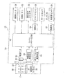
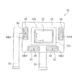
図1は、第1の実施形態であるデジタルカメラのブロック図である。図2は、手振れ補正装置を示した図である。 FIG. 1 is a block diagram of a digital camera according to the first embodiment. FIG. 2 is a diagram illustrating a camera shake correction apparatus.
デジタルカメラ10は、カメラ本体20と、カメラ本体20に着脱自在に装着される撮影レンズ30とを備え、撮影レンズ30には、固定レンズ群31A、変倍レンズ群31B、フォーカシングレンズ群31Cを含む複数のレンズ群から成る撮影光学系31が収納されている。カメラ上部にはレリーズボタン(図示せず)が設けられており、カメラ背面にはLCDなどの画像モニタ24が設置されている。
The
DSP(Digital Signal Processor)などで構成されるシステムコントロール回路40は、レリーズボタンさらには電源ボタン(図示せず)など操作部材に対する入力操作に応じて、撮影動作、画像記録処理、再生表示処理などカメラ全体の動作制御を行なう。カメラ動作制御に関するプログラムは、ROM(図示せず)などのメモリに記憶されている。
A
スルー画像を表示する場合、撮影光学系31、絞り32を通った被写体からの光が、イメージセンサ22の受光面に結像する。システムコントロール回路40では、イメージセンサ22から順次読み出される1フィールド又は1フレーム分の画素信号に対し、ホワイトバランス調整、色変換処理などの画像信号処理などを施し、カラー画像データを生成する。生成された画像データにより、リアルタイムの動画像がスルー画像として画像モニタ24に表示される。
When displaying a through image, light from a subject passing through the photographing
システムコントロール回路40は、レリーズボタンが半押しされると、撮影操作スイッチ26からの信号によって半押し操作を検出する。そして、コントラスト方式によるAF処理を実行し、フォーカシングレンズ群31Cを駆動して焦点調整を行う。また、生成される画像データから被写体像の明るさが検出されることにより、シャッタスピード、絞り値などの露出値を演算する。
When the release button is half-pressed, the
さらにシステムコントロール回路40は、撮影操作スイッチ26からの信号によってレリーズボタンの全押しを検出すると、絞り/シャッタ駆動回路23を制御し、演算された露出値に基づいて絞り32、シャッタ21等を駆動する。これによって、1フレーム分の画像信号がイメージセンサ22から読み出される。
Further, when the
システムコントロール回路40は、読み出された1フレーム分の画素信号に基づいて静止画像データを生成する。生成された静止画像データは、画像メモリ25に記録される。再生モードが設定されると、画像メモリ25に記憶された一連の記録画像のうち選択された画像が読み出され、画像モニタ24に再生表示される。
The
ユーザはメニュー画面において撮影内容を選択することが可能であり、例えば、ブラケット撮影、あるいは、長秒露光撮影などを設定することが可能である。長秒露光撮影が設定されると、撮影時に数秒あるいはそれ以上の長時間に渡るシャッタスピードを設定して撮影を行う。 The user can select the shooting content on the menu screen, and can set, for example, bracket shooting or long-second exposure shooting. When long-second exposure shooting is set, shooting is performed by setting a shutter speed over a long time of several seconds or more during shooting.
撮影レンズ30は、撮影光学系31の解像力、絞り32の開口径などのレンズ情報データを記憶する通信用メモリ33を備えている。撮影レンズ30がカメラ本体20に装着されると、記憶されたデータがシステムコントロール回路40へ送られる。
The photographing
カメラ本体20内には、像ブレ補正装置50が撮影光学系31の後方に配置されている。像ブレ補正装置50は、図2に示すように、固定支持基板に対して光軸垂直平面に沿って移動可能な可動ステージ54を備えている。ただし、図2は、可動ステージ54を前方(撮影レンズ側)から見た図である。
In the
イメージセンサ22の背面は回路基板22bに装着されており、回路基板22bの開口部54a中央部に位置するように、回路基板22bが可動ステージ54に取り付け固定されている。回路基板22bの背面にはイメージセンサ駆動用FPC(Flexible Printed Circuits)55が接続されている。
The back surface of the
可動ステージ54の前面には、一対の駆動用巻き線コイル(ボイスコイル)C1、C2が、イメージセンサ22の下方側に所定間隔離れて配置されており、また、イメージセンサ22の左右両サイドに一対の駆動用巻き線コイルC3、C4が配置されている。巻き線コイルC1、C2、C3、C4は、可動ステージ54の裏面に固定された駆動制御用FPC56に実装されており、可動ステージ54に形成された開口部54b1、54b2、54b3、54b4から可動ステージ54の前面側に露出している。
On the front surface of the
駆動制御用FPC56に実装された巻き線コイルC1、C2、C3の略中央には、ホールセンサH1、H2、H3が実装されている。前側ヨーク板(図示せず)の裏面(イメージセンサ22と向かい合う面)には、巻き線コイルC1、C2、C3、C4と対向する位置に永久磁石(図示せず)が配置されている。 Hall sensors H1, H2, and H3 are mounted at substantially the center of the winding coils C1, C2, and C3 mounted on the drive control FPC. Permanent magnets (not shown) are arranged at positions facing the winding coils C1, C2, C3, and C4 on the back surface (the surface facing the image sensor 22) of the front yoke plate (not shown).
巻き線コイルC3、C4に駆動電流が流れると、巻き線コイルC3、C4は電磁石として機能し、コイル近傍において磁界変化が生じる。前側ヨーク板に設けられた永久磁石と巻き線コイルC3、C4との磁気相互作用により、可動ステージ54がX方向(カメラ横方向)に沿って移動する。また、巻き線コイルC1、C2に駆動電流が流れると、同様に磁気相互作用によって可動ステージ54がY方向(カメラ縦方向)に移動する。
When a drive current flows through the winding coils C3 and C4, the winding coils C3 and C4 function as electromagnets, and a magnetic field change occurs in the vicinity of the coils. Due to the magnetic interaction between the permanent magnets provided on the front yoke plate and the winding coils C3 and C4, the
ジャイロセンサ28は、カメラ10のヨーイング、ピッチングの角度ぶれと、光軸周りの回転ぶれを検知する複数のジャイロセンサ28で構成されており、カメラ本体20のX,Y,Z3軸回りの角速度をそれぞれ検出する。演算部80は、ジャイロセンサ28からの出力信号(第1出力信号)に基づいて角度ぶれ、回転ぶれによる像ブレ補正量(変位量)を算出する。ただし、像ブレ補正量はX方向、Y方向それぞれの成分ごとに求められる。
The gyro sensor 28 is composed of a plurality of gyro sensors 28 that detect angular shakes of yawing and pitching of the
一方、加速度センサ29は、手振れのうち平行ぶれが生じたときの加速度を検知する。加速度センサ29は、例えばイメージセンサ22背面付近で光軸上に沿った場所に配置されている。ただし、加速度センサ29は、カメラ10を通常姿勢でユーザが保持したときの水平方向に対応するX方向(カメラ横方向)に沿った加速度検出用のセンサと、それに垂直なY方向に沿った加速度検出用のセンサをそれぞれ備え、X方向、Y方向に沿ってカメラ10が変位したときの加速度をそれぞれ検出する。演算部60は、加速度センサ29からの出力信号(第2出力信号)に基づいて、平行ぶれによる像ブレ補正量(変位量)を算出する。
On the other hand, the
システムコントロール回路40は、ジャイロセンサ28、加速度センサ29からの出力信号に基づいて像ブレ補正量を演算する。そして、移動部材駆動回路59へ駆動信号を出力し、手振れによる像ブレを相殺するように可動ステージ54をX−Y平面に沿って移動させる。このとき、ホールセンサH1〜H3からの信号に基づいて可動ステージ54の位置をフィードバック制御する。
The
加速度センサ29からの出力信号には、手振れによって生じる平行ぶれ方向の加速度成分だけでなく、重力加速度成分が含まれている。演算部60は、以下説明するように、ジャイロセンサ28からの出力信号を用いずに重力加速度成分を除去する。
The output signal from the
図3は、演算部60のブロック図である。ここでは、Y方向に応じた加速度センサ出力信号に対する演算部の構成について説明する。X方向に応じた加速度センサ出力信号に対しても同様の構成となる。
FIG. 3 is a block diagram of the
演算部60は、ローパスフィルタ(LPF)62とハイパスフィルタ(HPF)64とを備え、さらに、HPF66、積分器68、HPF70、積分器72とを備える。HPF64、66は、重力加速度成分を除去する機能をもち、積分器68、HPF70、積分器72によって重力加速度成分を除いた並進振れ成分の像ブレ量を演算する。加速度センサ29から出力された信号は、LPF62の側(以下、サブ側という)とHPF66の側(以下、メイン側という)に分岐される。
The
演算部60のサブ側では、LPF62によって高周波ノイズが除去された後、HPF64によって重力加速度成分が除去される。重力加速度(=9.8m/s2)は一定値であり、その周波数は極めて小さいものとみなせる。HPF64は、重力加速度成分を短時間で正確に取り除く機能を有し、ここではHPF64のカットオフ周波数fmが、比較的大きな5Hzに定められている。
On the sub-side of the
HPF64は、積分器(図示せず)を備えており、重力加速度成分に応じた値が積算される。カットオフ周波数fm=5Hzの場合、時定数(=1/2πfm)はおよそ0.03秒となる。一般的に時定数の6倍で100%近く収束することから、およそ0.18秒程度で収束する。
The
一方、メイン側に送られた加速度センサ29からの出力信号は、HPF66へ入力され、重力加速度成分が除去される。重力加速度成分除去後の信号は、平行振れに応じた加速度成分に相当し、積分器68、HPF70、積分器72を経由することで2回積分される。これにより、手振れ(並進振れ)による像ブレ量の値がシステムコントロール回路40へ入力される。システムコントロール回路40では、撮影倍率に応じて並進振れによる像ブレ量が補正される。
On the other hand, the output signal from the
HPF66は、HPF64と同様の回路構成であって、加速度センサ29からの出力信号が入力されると、重力加速度成分に応じた値が積分器に積算される。手振れの周波数が1Hz〜10Hzの範囲にあり、1Hz前後の平行振れ成分もHPF66を通過させることから、HPF66のカットオフ周波数fnは、サブ側のHPF64と比べて小さく設定されている。
The
HPF66の非常に小さいカットオフ周波数fnでは、カメラ10の姿勢変化が生じてから平行振れの検出を有効に行うまでに時間がかかり、その間有効に像ブレ補正を行うことができない。そこで、サブ側のHPF64の積分値を利用したメイン側のHPF66の演算処理を、撮影シーケンスに応じて行う。
With the extremely low cutoff frequency fn of the
具体的には、電源が立ち上がると、HPF64とHPF66両方において内部演算処理が行われ、図示しないレリーズボタンが半押し状態になる、あるいは電源立ち上げ直後などのタイミングで、サブ側のHPF64の積分値に対してカットオフ周波数比fm/fnを乗じた値を、HPF66に入力し、HPF66の積分値として出力させる。レリーズボタンが全押しされると、HPF64からHPF66への積分値入力を停止し、HPF66の動作によって重力加速度成分を除去する。
Specifically, when the power is turned on, internal calculation processing is performed in both the
本実施形態では、外乱などによって像ブレ量の誤差が増大するのを防ぐため、角度ぶれ、回転ぶれに対する像ブレ補正の実行/非実行および平行ぶれに対する像ブレ補正の実行/非実行を、ジャイロセンサ28からの出力信号に基づいて判断する。以下、これについて詳述する。 In the present embodiment, in order to prevent an increase in the image blur amount error due to disturbance or the like, execution / non-execution of image blur correction for angular blur and rotation blur and execution / non-execution of image blur correction for parallel blur are performed by a gyro. A determination is made based on the output signal from the sensor 28. This will be described in detail below.
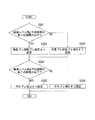
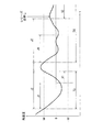
図4は、撮影シーケンスのフローチャートである。図5は、像ブレ補正ON/OFFの判定処理を示すフローチャートである。図6は、角速度の時系列的変化を示したグラフである。 FIG. 4 is a flowchart of the photographing sequence. FIG. 5 is a flowchart showing the image blur correction ON / OFF determination process. FIG. 6 is a graph showing time-series changes in angular velocity.
電源がON状態になると、像ブレ補正ON/OFF判定を実行開始する(S101)。そして、レリーズボタンが半押しされると合焦動作、露出演算処理が実行される。レリーズボタンが全押しされると、像ブレ補正のオンオフ判定処理を終了する(S101〜S106)。したがって、レリーズ全押し時あるいはその直前の判定結果に基づいて、露光期間中の像ブレ補正処理を行う。なお、レリーズ半押しタイミングに合わせて像ブレ補正処理を実行してもよく、また、電源ON直後から続けて像ブレ補正処理を実行してもよい。 When the power is turned on, the image blur correction ON / OFF determination is started (S101). When the release button is pressed halfway, a focusing operation and an exposure calculation process are executed. When the release button is fully pressed, the image blur correction on / off determination process ends (S101 to S106). Therefore, image blur correction processing during the exposure period is performed based on the determination result immediately before or when the release is fully pressed. Note that the image blur correction process may be executed in accordance with the release half-press timing, or the image blur correction process may be executed immediately after the power is turned on.
図5に示す像ブレ補正ON/OFFの判定処理は、所定時間間隔で実行される。最初に、ジャイロセンサ28によって検出される角速度が、閾値となる基準レベルA以下であるか否かが判断される(S201)。ただし、角速度および基準レベルA(第1基準レベル)の絶対値で比較判断する。角速度が基準レベルA以下である場合、角度ぶれ、回転ぶれに対する像ブレ補正をOFF設定にする(S203)。OFF設定の場合、角度ぶれ、回転ぶれに対する像ブレ量は0に設定される。一方、角速度が基準レベルAより大きい場合、角度ぶれ、回転ぶれに対する像ブレ補正をON設定にする(S204)。 The image blur correction ON / OFF determination process shown in FIG. 5 is executed at predetermined time intervals. First, it is determined whether or not the angular velocity detected by the gyro sensor 28 is equal to or lower than a reference level A serving as a threshold (S201). However, the comparison is made based on the angular velocity and the absolute value of the reference level A (first reference level). When the angular velocity is equal to or lower than the reference level A, the image blur correction for angular blur and rotational blur is set to OFF (S203). In the case of the OFF setting, the image blur amount with respect to angular blur and rotational blur is set to zero. On the other hand, if the angular velocity is greater than the reference level A, the image blur correction for angular blur and rotational blur is set to ON (S204).
次に、角速度が基準レベルB(第2基準レベル)以下であるか否かが判断される(S204)。第2基準レベルBは基準レベルAよりも絶対値が大きい。角速度が基準レベル以下である場合、平行ぶれに対する像ブレ補正をOFF設定にする(S206)。一方、角速度が基準レベルを超える場合、平行ぶれに対する像ブレ補正をON設定にする(S205)。 Next, it is determined whether the angular velocity is equal to or lower than a reference level B (second reference level) (S204). The second reference level B has a larger absolute value than the reference level A. If the angular velocity is below the reference level, image blur correction for parallel blur is set to OFF (S206). On the other hand, if the angular velocity exceeds the reference level, image blur correction for parallel blur is set to ON (S205).
したがって、角速度が基準レベルA以下の場合、角度ぶれおよび回転ぶれに対する像ブレ補正と、平行ぶれに対する像ブレ補正がともにOFF設定になる。角速度が基準レベルAを超えるが基準レベルB以下にある場合、角度ぶれおよび回転ぶれに対する像ブレ補正はON設定になる一方、平行ぶれに対する像ブレ補正はOFF設定になる。そして、角速度が基準レベルBを超える場合、角度ぶれおよび回転ぶれに対する像ブレ補正と、平行ぶれに対する像ブレ補正がともにON設定になる。 Accordingly, when the angular velocity is equal to or lower than the reference level A, both the image blur correction for the angular blur and the rotation blur and the image blur correction for the parallel blur are both set to OFF. When the angular velocity exceeds the reference level A but is below the reference level B, image blur correction for angular blur and rotational blur is set to ON, while image blur correction for parallel blur is set to OFF. When the angular velocity exceeds the reference level B, both image blur correction for angular blur and rotational blur and image blur correction for parallel blur are both set to ON.
ここでは、X,Y,Z軸の中の1つの軸のジャイロセンサからの出力に基づいて判定処理を行っているが、2つ、3つの軸のジャイロセンサの出力信号を用いる場合、それらを複合的に取り扱う。例えば、重み付け係数を各軸のジャイロセンサ出力値に乗じて加算するなどして出力信号を合算する。 Here, the determination processing is performed based on the output from the gyro sensor of one of the X, Y, and Z axes, but when using the output signals of the gyro sensor of two or three axes, Handle multiple times. For example, the output signals are added up by multiplying the gyro sensor output value of each axis by the weighting coefficient and adding the weighting coefficient.
図6には、電源ONから所定時間間隔で検出される角速度の時系列的変化を示している。角速度が基準レベルAと基準レベルBとの間にある期間をT1、基準レベルA以下の期間をT2で表している。レリーズ全押しのタイミングが図6に示すように期間T1で生じると、平行ぶれに対する像ブレ補正がOFF設定される。 FIG. 6 shows a time-series change in angular velocity detected at predetermined time intervals after the power is turned on. A period in which the angular velocity is between the reference level A and the reference level B is represented by T1, and a period below the reference level A is represented by T2. When the release full press timing occurs in the period T1 as shown in FIG. 6, the image blur correction for parallel blur is set to OFF.
例えば、三脚を使用し、撮影倍率を高めて長秒露光撮影を行う間、風の影響でカメラ10が軽く揺れる場合がある。このとき、累積的検出誤差が大きくなる平行ぶれの像ブレ補正は実行されない。一方、角度および回転ぶれに対する像ブレ補正は実行されることにより、カメラ10の揺れに対する像ブレ補正を行うことができる。
For example, while using a tripod and increasing the shooting magnification to perform long-second exposure shooting, the
また、ユーザが保持してカメラ撮影を行う場合、角速度が基準レベルBを超えるため、角度ぶれ、回転ぶれおよび平行ぶれに対して適切に像ブレ補正処理を実行することができる。基準レベルA,Bの大きさは、風など外乱によるカメラにかかる力と検出誤差量、手で保持して手振れしたときの角速度範囲などを考慮して定めればよい。 Further, when the user holds the camera and shoots the image, the angular velocity exceeds the reference level B, so that the image blur correction process can be appropriately executed for angular blur, rotational blur, and parallel blur. The sizes of the reference levels A and B may be determined in consideration of the force applied to the camera due to disturbance such as wind, the amount of detection error, the angular velocity range when the camera shakes while being held by hand.
図5に示した像ブレ補正ON/OFFの判定処理は、レリーズボタン全押しに応じて終了する(S106)。そして、その判定結果によって角度ぶれ、回転ぶれに対する像ブレ補正を実行開始し、あるいは非実行とする(S107、S108)。同様に、判定結果に基づいて平行ぶれに対する像ブレ補正を実行開始し、あるいは非実行とする(S109、S110)。露光期間が経過すると、像ブレ補正処理の実行は終了する(S111〜S113)。なお、電源直後からライブビュー表示中続けて判定処理をおこなってもよく、あるいはレリーズ半押し操作に応じて判定処理を行い、その判定結果に基づいて像ブレ補正ON/OFF設定してもよい。 The image blur correction ON / OFF determination process shown in FIG. 5 ends in response to the release button being fully pressed (S106). Then, depending on the determination result, execution of image blur correction for angular blur and rotational blur starts or is not performed (S107, S108). Similarly, execution of image blur correction for parallel blur is started or not executed based on the determination result (S109, S110). When the exposure period has elapsed, the execution of the image blur correction process ends (S111 to S113). Note that the determination process may be performed immediately after the power supply is being displayed during live view display, or the determination process may be performed in response to a release half-press operation, and image blur correction ON / OFF may be set based on the determination result.
このように本実施形態によれば、像ブレ補正処理を実行するデジタルカメラ10において、角速度が基準レベルA以下、基準レベルB以下であるか否かを判断する。角速度の基準レベルA,Bに対する大小に応じて、角度ぶれおよび回転ぶれに対する像ブレ補正をON/OFF設定し、平行ぶれに対する像ブレ補正をON/OFF設定する。
As described above, according to the present embodiment, in the
角速度を用いて像ブレ補正実行するか否かを判断する代わりに、ジャイロセンサの出力そのもの、フィルタ処理をかけたもの、積分値すなわち位置(変位)などを判断材料にしてもよい。また、基準レベルAの方を基準レベルBよりも大きくして基準レベルの大小を入れ替えてもよい。例えば、基準レベルジャイロセンサの精度などの問題で角度ぶれ、回転ぶれの方が平行ぶれよりも検出誤差量が顕著になるカメラなどに対して適用することができる。 Instead of determining whether or not to perform image blur correction using the angular velocity, the output itself of the gyro sensor, the filtered one, the integrated value, that is, the position (displacement), or the like may be used as a determination material. Further, the reference level A may be made larger than the reference level B, and the reference level may be switched. For example, the present invention can be applied to a camera or the like in which the amount of detection error is more noticeable in angular blur and rotational blur than in parallel blur due to problems such as accuracy of the reference level gyro sensor.
次に、図7、8を用いて第2の実施形態であるデジタルカメラについて説明する。第2の実施形態では、角速度が基準レベル以下である継続期間の長さに基づいて像ブレ補正ON/OFFの判定を行う。 Next, a digital camera according to the second embodiment will be described with reference to FIGS. In the second embodiment, the image blur correction ON / OFF is determined based on the length of the duration in which the angular velocity is equal to or lower than the reference level.
図7は、第2の実施形態における像ブレ補正ON/OFFの判定処理を示すフローチャートである。図8は、角速度の時系列的変化を示したグラフである。 FIG. 7 is a flowchart showing image blur correction ON / OFF determination processing according to the second embodiment. FIG. 8 is a graph showing time-series changes in angular velocity.
ステップS301では、角速度が基準レベルM以下であるか否かが判断されるとともに、基準レベルM以下である期間、すなわち角速度が基準レベルMを超えるまでの期間がカウントされる。そして、基準レベルM以下である期間が閾値となる第1の基準期間J1以下である場合、角度ぶれ、回転ぶれに対する像ブレ補正をON設定する。基準期間J1を超える場合、角度ぶれ、回転ぶれに対する像ブレ補正をOFF設定にする(S302、S303)。 In step S301, it is determined whether or not the angular velocity is equal to or lower than the reference level M, and a period during which the angular velocity is equal to or lower than the reference level M, that is, a period until the angular velocity exceeds the reference level M is counted. When the period that is equal to or less than the reference level M is equal to or less than the first reference period J1 that is a threshold value, the image blur correction for angular blur and rotational blur is set to ON. When the reference period J1 is exceeded, image blur correction for angular blur and rotational blur is set to OFF (S302, S303).
ステップS304では、基準レベルM以下の期間が第2の基準期間J2以下であるか否かが判断される。基準レベルM以下の期間が第2の基準期間J2以下である場合、平行ぶれに対する像ブレ補正がON設定になり、基準レベルM以下の期間が第2の基準期間J2を超える場合、平行ぶれに対する像ブレ補正がOFF設定になる(S305、S306)。なお、角速度がいったん基準レベルMを超えてから再び基準レベルM以下になるのに合わせて、基準レベルM以下の期間が再びカウント開始される。 In step S304, it is determined whether or not the period below the reference level M is less than or equal to the second reference period J2. When the period below the reference level M is the second reference period J2 or less, the image blur correction for parallel blur is set to ON, and when the period below the reference level M exceeds the second reference period J2, the parallel blur is corrected. Image blur correction is set to OFF (S305, S306). In addition, as the angular velocity once exceeds the reference level M and then becomes the reference level M or less again, the period of the reference level M or less is started again.
図8では、基準レベルM以下の期間をT3、T4で示している。期間T3の場合、第1の基準期間J1を経過してから期間J2に達するまでの区間X1では、基準レベルM以下の期間が第1の基準期間J1を超える一方で第2の基準期間J2以下となる。そのため、角度ぶれ、回転ぶれに対する像ブレ補正はOFFに設定される一方(S303)、平行ぶれに対する像ブレ補正はON設定される(S305)。 In FIG. 8, periods below the reference level M are indicated by T3 and T4. In the period T3, in the section X1 from the elapse of the first reference period J1 until the period J2 is reached, the period of the reference level M or less exceeds the first reference period J1, while the second reference period J2 or less. It becomes. Therefore, image blur correction for angular blur and rotational blur is set to OFF (S303), while image blur correction for parallel blur is set to ON (S305).
一方、期間T4の中で第2の基準期間J2以降の区間X2では、第1、第2の基準期間J1、J2を超えた期間になっている。そのため、レリーズボタン全押しタイミングが図5に示すタイミングで行われ場合、角度ぶれ、回転ぶれ、および平行ぶれに対する像ブレ補正がいずれもOFF設定される。 On the other hand, in the period T4, the section X2 after the second reference period J2 is a period exceeding the first and second reference periods J1 and J2. Therefore, when the release button full press timing is performed at the timing shown in FIG. 5, image blur correction for angular blur, rotational blur, and parallel blur is all set to OFF.
このように、像ブレ量が基準レベルM以下である期間がどの程度続いていたかを判断基準として像ブレ補正ON/OFF設定することにより、三脚撮影、手持ち撮影いずれにおいても検出誤差量を抑えて像ブレ補正処理を実行することができる。例えば、手持ち撮影において手振れを一瞬だけ抑えても像ブレ補正OFFに設定されない。一方で、三脚撮影では、フレーミング平行など角度ブレを伴わないカメラの動きに対処することができる。なお、第1の実施形態と同様、角度ぶれ、回転ぶれを検出するジャイロセンサの誤検出量が相対的に大きい場合、第1の基準期間J1、J2の大小を入れ替えてもよい。また、第1の基準期間J1、J2については、手持ち撮影、三脚撮影時に検出される振れ信号の変化を比較などして定めればよい。 In this way, by setting the image blur correction ON / OFF based on how long the period during which the image blur amount is equal to or less than the reference level M has been set, the detection error amount can be suppressed in both tripod shooting and handheld shooting. Image blur correction processing can be executed. For example, even if hand shake is suppressed for a moment in hand-held shooting, image blur correction is not set to OFF. On the other hand, in tripod photography, it is possible to deal with camera movements that do not involve angular blur such as framing parallelism. As in the first embodiment, when the misdetection amount of the gyro sensor that detects angular shake and rotational shake is relatively large, the sizes of the first reference periods J1 and J2 may be switched. The first reference periods J1 and J2 may be determined by comparing changes in shake signals detected during handheld shooting and tripod shooting.
10 デジタルカメラ(撮像装置)
20 カメラ本体
28 ジャイロセンサ(第1ぶれ検出手段)
29 加速度センサ(第2ぶれ検出手段)
30 撮影レンズ(光学機器)
40 システムコントロール回路(制御部)
50 像ブレ補正装置(像ブレ補正手段)
10 Digital camera (imaging device)
20 Camera body 28 Gyro sensor (first shake detection means)
29 Acceleration sensor (second shake detection means)
30 Photography lens (optical equipment)
40 System control circuit (control unit)
50 Image blur correction device (image blur correction means)
Claims (6)
撮像装置の平行ぶれを検出する第2ぶれ検出手段と、
前記第1ぶれ検出手段の出力信号と前記第2ぶれ検出手段の出力信号とに基づいて像ブレ補正手段を駆動制御し、像ブレを抑える制御部とを備え、
前記制御部が、前記第1ぶれ検出手段の出力演算値が第1基準レベル以下の場合、角度ぶれおよび/又は回転ぶれに対する像ブレ補正を実行せず、
前記制御部が、前記第1ぶれ検出手段の出力演算値が第1基準レベルとは異なる第2基準レベル以下の場合、平行ぶれに対する像ブレ補正を実行しないことを特徴とする防振制御装置。 First blur detection means for detecting angular blur and / or rotational blur of the imaging device;
Second shake detection means for detecting parallel shake of the imaging device;
A control unit that controls driving of the image blur correction unit based on the output signal of the first blur detection unit and the output signal of the second blur detection unit and suppresses the image blur;
When the output calculation value of the first shake detection unit is equal to or lower than the first reference level, the control unit does not perform image blur correction for angular shake and / or rotational shake,
The image stabilization control apparatus, wherein the control unit does not perform image blur correction for parallel blur when an output calculation value of the first blur detection unit is equal to or lower than a second reference level different from the first reference level.
撮像装置の平行ぶれを検出する第2ぶれ検出手段と、
前記第1ぶれ検出手段から出力される角度ぶれおよび/又は回転ぶれに応じた第1出力信号と、前記第2ぶれ検出手段から出力される平行ぶれに応じた第2出力信号とに基づいて像ブレ補正手段を駆動制御し、像ブレを抑える制御部とを備え、
前記制御部が、前記第1ぶれ検出手段の出力演算値が、第1の基準期間基準レベル以下の場合、角度ぶれおよび/又は回転ぶれに対する像ブレ補正を実行し、
前記制御部が、前記第1ぶれ検出手段の出力演算値が、第1の基準期間とは異なる第2の基準期間基準レベル以下の場合、平行ぶれに対する像ブレ補正を実行することを特徴とする防振制御装置。 First blur detection means for detecting angular blur and / or rotational blur of the imaging device;
Second shake detection means for detecting parallel shake of the imaging device;
The image is based on a first output signal corresponding to the angular blur and / or rotational blur output from the first blur detection unit and a second output signal corresponding to the parallel blur output from the second blur detection unit. A control unit that controls driving of the blur correction unit and suppresses image blur,
The controller performs image blur correction for angular blur and / or rotational blur when an output calculation value of the first blur detection unit is equal to or lower than a first reference period reference level;
The control unit executes image blur correction for parallel blurring when an output calculation value of the first blur detection unit is equal to or lower than a second reference period reference level different from the first reference period. Anti-vibration control device.
Priority Applications (1)
| Application Number | Priority Date | Filing Date | Title |
|---|---|---|---|
| JP2016083752A JP6753126B2 (en) | 2016-04-19 | 2016-04-19 | Anti-vibration control device |
Applications Claiming Priority (1)
| Application Number | Priority Date | Filing Date | Title |
|---|---|---|---|
| JP2016083752A JP6753126B2 (en) | 2016-04-19 | 2016-04-19 | Anti-vibration control device |
Publications (2)
| Publication Number | Publication Date |
|---|---|
| JP2017194529A true JP2017194529A (en) | 2017-10-26 |
| JP6753126B2 JP6753126B2 (en) | 2020-09-09 |
Family
ID=60154878
Family Applications (1)
| Application Number | Title | Priority Date | Filing Date |
|---|---|---|---|
| JP2016083752A Active JP6753126B2 (en) | 2016-04-19 | 2016-04-19 | Anti-vibration control device |
Country Status (1)
| Country | Link |
|---|---|
| JP (1) | JP6753126B2 (en) |
Cited By (1)
| Publication number | Priority date | Publication date | Assignee | Title |
|---|---|---|---|---|
| KR102844913B1 (en) * | 2024-12-31 | 2025-08-11 | 국방과학연구소 | Method of controlling gimbal and electronic apparatus therefor |
Citations (10)
| Publication number | Priority date | Publication date | Assignee | Title |
|---|---|---|---|---|
| JPH0456831A (en) * | 1990-06-22 | 1992-02-24 | Canon Inc | Image blur correction device and device applied to the device |
| JP2006084540A (en) * | 2004-09-14 | 2006-03-30 | Nikon Corp | Blur correction device |
| WO2007099908A1 (en) * | 2006-02-27 | 2007-09-07 | Matsushita Electric Industrial Co., Ltd. | Wearable terminal, mobile imaging sound collecting device, and device, method, and program for implementing them |
| JP2012078495A (en) * | 2010-09-30 | 2012-04-19 | Fujifilm Corp | Imaging device, shake correction device, and shake correction method |
| JP2012163824A (en) * | 2011-02-08 | 2012-08-30 | Nikon Corp | Shake correction apparatus and optical device |
| JP2013059020A (en) * | 2011-08-18 | 2013-03-28 | Canon Inc | Image capturing apparatus and control method therefor |
| JP2013141155A (en) * | 2012-01-05 | 2013-07-18 | Nikon Corp | Imaging device |
| JP2014082669A (en) * | 2012-10-17 | 2014-05-08 | Ricoh Imaging Co Ltd | Camera-shake correction device and camera |
| JP2015045885A (en) * | 2014-11-28 | 2015-03-12 | 株式会社ニコン | Vibration correction device, lens barrel, and camera system |
| JP2015172610A (en) * | 2014-03-11 | 2015-10-01 | キヤノン株式会社 | Image blur correction apparatus, control method thereof, optical device, and imaging apparatus |
-
2016
- 2016-04-19 JP JP2016083752A patent/JP6753126B2/en active Active
Patent Citations (10)
| Publication number | Priority date | Publication date | Assignee | Title |
|---|---|---|---|---|
| JPH0456831A (en) * | 1990-06-22 | 1992-02-24 | Canon Inc | Image blur correction device and device applied to the device |
| JP2006084540A (en) * | 2004-09-14 | 2006-03-30 | Nikon Corp | Blur correction device |
| WO2007099908A1 (en) * | 2006-02-27 | 2007-09-07 | Matsushita Electric Industrial Co., Ltd. | Wearable terminal, mobile imaging sound collecting device, and device, method, and program for implementing them |
| JP2012078495A (en) * | 2010-09-30 | 2012-04-19 | Fujifilm Corp | Imaging device, shake correction device, and shake correction method |
| JP2012163824A (en) * | 2011-02-08 | 2012-08-30 | Nikon Corp | Shake correction apparatus and optical device |
| JP2013059020A (en) * | 2011-08-18 | 2013-03-28 | Canon Inc | Image capturing apparatus and control method therefor |
| JP2013141155A (en) * | 2012-01-05 | 2013-07-18 | Nikon Corp | Imaging device |
| JP2014082669A (en) * | 2012-10-17 | 2014-05-08 | Ricoh Imaging Co Ltd | Camera-shake correction device and camera |
| JP2015172610A (en) * | 2014-03-11 | 2015-10-01 | キヤノン株式会社 | Image blur correction apparatus, control method thereof, optical device, and imaging apparatus |
| JP2015045885A (en) * | 2014-11-28 | 2015-03-12 | 株式会社ニコン | Vibration correction device, lens barrel, and camera system |
Cited By (1)
| Publication number | Priority date | Publication date | Assignee | Title |
|---|---|---|---|---|
| KR102844913B1 (en) * | 2024-12-31 | 2025-08-11 | 국방과학연구소 | Method of controlling gimbal and electronic apparatus therefor |
Also Published As
| Publication number | Publication date |
|---|---|
| JP6753126B2 (en) | 2020-09-09 |
Similar Documents
| Publication | Publication Date | Title |
|---|---|---|
| JP4789614B2 (en) | Anti-vibration control device and control method thereof | |
| CN101106655B (en) | Anti-shake device | |
| US9170429B2 (en) | Optical apparatus and image capturing apparatus, and method of controlling the same and storage medium | |
| KR101528860B1 (en) | Method and apparatus for correcting a shakiness in digital photographing apparatus | |
| JP4789789B2 (en) | Imaging device | |
| JP5409342B2 (en) | Imaging apparatus and control method thereof | |
| JP6282152B2 (en) | Imaging apparatus and control method thereof | |
| US20110176015A1 (en) | Method and apparatus for processing digital image | |
| JP4994756B2 (en) | Anti-vibration control device, optical apparatus including the same, imaging device, and control method of anti-vibration control device | |
| JP2016170285A (en) | Image blur correction apparatus, optical apparatus, imaging apparatus, and control method | |
| JP6728881B2 (en) | Anti-vibration control device | |
| CN101162351A (en) | Dust removing device for photographic device | |
| JP2012163824A (en) | Shake correction apparatus and optical device | |
| CN101106653A (en) | Anti-shake device | |
| JP6753126B2 (en) | Anti-vibration control device | |
| JP2017194531A (en) | Vibration proof control device | |
| JP2006293218A (en) | Shooting system | |
| JP6711099B2 (en) | Imaging device | |
| JP6862675B2 (en) | Anti-vibration control device | |
| JP2008131448A (en) | camera | |
| JP6738151B2 (en) | Imaging device and control method thereof | |
| JP6728825B2 (en) | Imaging device | |
| JP2012042589A (en) | Image shake correction mechanism, lens barrel, and image sensor | |
| JP6728640B2 (en) | Imaging device | |
| JP6458618B2 (en) | Imaging device |
Legal Events
| Date | Code | Title | Description |
|---|---|---|---|
| A621 | Written request for application examination |
Free format text: JAPANESE INTERMEDIATE CODE: A621 Effective date: 20190212 |
|
| A977 | Report on retrieval |
Free format text: JAPANESE INTERMEDIATE CODE: A971007 Effective date: 20191213 |
|
| A131 | Notification of reasons for refusal |
Free format text: JAPANESE INTERMEDIATE CODE: A131 Effective date: 20191224 |
|
| A521 | Request for written amendment filed |
Free format text: JAPANESE INTERMEDIATE CODE: A523 Effective date: 20200225 |
|
| A131 | Notification of reasons for refusal |
Free format text: JAPANESE INTERMEDIATE CODE: A131 Effective date: 20200428 |
|
| A521 | Request for written amendment filed |
Free format text: JAPANESE INTERMEDIATE CODE: A523 Effective date: 20200629 |
|
| TRDD | Decision of grant or rejection written | ||
| A01 | Written decision to grant a patent or to grant a registration (utility model) |
Free format text: JAPANESE INTERMEDIATE CODE: A01 Effective date: 20200721 |
|
| A61 | First payment of annual fees (during grant procedure) |
Free format text: JAPANESE INTERMEDIATE CODE: A61 Effective date: 20200803 |
|
| R150 | Certificate of patent or registration of utility model |
Ref document number: 6753126 Country of ref document: JP Free format text: JAPANESE INTERMEDIATE CODE: R150 |
|
| R250 | Receipt of annual fees |
Free format text: JAPANESE INTERMEDIATE CODE: R250 |
|
| R250 | Receipt of annual fees |
Free format text: JAPANESE INTERMEDIATE CODE: R250 |
|
| R250 | Receipt of annual fees |
Free format text: JAPANESE INTERMEDIATE CODE: R250 |