JP2019059372A - Work vehicle - Google Patents
Work vehicle Download PDFInfo
- Publication number
- JP2019059372A JP2019059372A JP2017186231A JP2017186231A JP2019059372A JP 2019059372 A JP2019059372 A JP 2019059372A JP 2017186231 A JP2017186231 A JP 2017186231A JP 2017186231 A JP2017186231 A JP 2017186231A JP 2019059372 A JP2019059372 A JP 2019059372A
- Authority
- JP
- Japan
- Prior art keywords
- gas spring
- loading platform
- locking pin
- vehicle
- along
- Prior art date
- Legal status (The legal status is an assumption and is not a legal conclusion. Google has not performed a legal analysis and makes no representation as to the accuracy of the status listed.)
- Granted
Links
Images


Landscapes
- Fluid-Damping Devices (AREA)
Abstract
【課題】荷台の姿勢変更の際に補助力を付与するガススプリングが損傷するおそれを少なくすることが望まれていた。【解決手段】荷物積載用の水平姿勢と荷物を外方に排出可能な傾斜姿勢とにわたり揺動自在に車体側固定部20に支持された荷台4と、荷台4の姿勢変更に伴う揺動作用箇所と車体側固定部20の支持部59とにわたって設けられ、荷台4の姿勢切り換えの際に補助力を付与するガススプリング55とが備えられ、ガススプリング55と支持部59との接続箇所に、伸長操作による補助力の付与が可能であるとともに、ガススプリング55が最伸長状態又はそれに近い状態であるときに、ガススプリング55と支持部59との間で伸長方向に沿う設定範囲内での相対移動を許容する融通部YDが設けられている。【選択図】図9An object of the present invention is to reduce the risk of damage to a gas spring that applies an assisting force when changing the attitude of a loading platform. SOLUTION: A loading platform 4 supported by a vehicle body side fixed portion 20 so as to be swingable in a horizontal attitude for loading luggage and an inclined attitude capable of discharging a load outward; A gas spring 55 is provided over the portion and the support portion 59 of the vehicle body side fixed portion 20 and provides an assisting force at the time of the posture switching of the loading platform 4, and the connection portion between the gas spring 55 and the support portion 59 While it is possible to apply an assisting force by the extension operation, and when the gas spring 55 is at or near the maximum extension state, the relative position of the gas spring 55 and the support portion 59 in the set range along the extension direction A flexible section YD is provided to allow movement. [Selected figure] Figure 9
Description
本発明は、揺動自在に支持された荷台を手動で揺動操作する際に、補助力を付与するガススプリングが備えられている作業車に関する。 The present invention relates to a working vehicle provided with a gas spring that applies an assisting force when manually swinging a swingably supported platform.
上記構成の作業車では、従来、ガススプリングは、荷台の姿勢変更に伴う揺動作用箇所と車体側固定部とにわたって設けられ、ガススプリングと荷台との接続箇所、及び、ガススプリングと車体側固定部との接続箇所の夫々において、1つの軸芯周りで揺動自在に枢支連結される構成となっていた(例えば、特許文献1参照)。 In the working vehicle of the above configuration, conventionally, the gas spring is provided over the swing action location and the vehicle body side fixing part along with the posture change of the loading platform, the connection location between the gas spring and the loading platform, and the gas spring and the vehicle location fixing In each of the connection points with the parts, it is configured to be pivotally connected pivotably around one axis (see, for example, Patent Document 1).
上記従来構成は、ガススプリングと荷台との間、及び、ガススプリングと車体側固定部との間の夫々において、互いに揺動自在に枢支連結されることで、荷台の姿勢変化を許容しながら、補助力を付与することが可能な状態でガススプリングの伸縮操作を行うことができる。 According to the above-described conventional configuration, the posture change of the loading platform is permitted by pivotally connecting each other between the gas spring and the loading platform and between the gas spring and the vehicle body side fixing portion so as to be swingable relative to each other. The expansion and contraction operation of the gas spring can be performed in a state in which the auxiliary force can be applied.
ガススプリングの補助力の付与を伴って手動にて荷台が姿勢変更され、ガススプリングが最も伸長した状態になると姿勢変更動作は終了するというのが、通常の姿勢切り換え操作である。しかし、このようにガススプリングが最も伸長した状態になっているにもかかわらず、伸長姿勢のガススプリングを更に伸長させる方向に引っ張り力が作用することがある。例えば、操作者が荷台の姿勢変更が未だ終了していないと誤って判断して、ガススプリングを更に伸長させる方向に荷台を揺動操作したり、荷台が傾斜姿勢であるときに、荷台に他物が接当してガススプリングを更に伸長させる方向に無理な力が掛かることがある。このような無理な力が掛かる状態が繰り返し発生すると、ガススプリングが損傷するおそれがある。 It is a normal posture switching operation that the posture change operation is finished when the posture of the loading platform is manually changed with the application of the assisting force of the gas spring and the gas spring is in the most extended state. However, even though the gas spring is in the most extended state as described above, a tensile force may act in the direction to further extend the gas spring in the extended position. For example, when the operator erroneously determines that the change of the posture of the carrier has not been completed, the carrier swings in the direction to further extend the gas spring, or when the carrier is in the inclined posture, An object may come in contact and an excessive force may be applied in the direction to further extend the gas spring. If such an excessive force is applied repeatedly, the gas spring may be damaged.
そこで、荷台の姿勢変更の際に補助力を付与するガススプリングが損傷するおそれを少なくすることが望まれていた。 Therefore, it has been desired to reduce the possibility of damage to the gas spring that applies an assisting force when the attitude of the loading platform is changed.
本発明に係る作業車の特徴構成は、
荷物積載用の水平姿勢と荷物を外方に排出可能な傾斜姿勢とにわたり揺動自在に車体側固定部に支持された荷台と、 前記荷台の姿勢変更に伴う揺動作用箇所と前記車体側固定部とにわたって設けられ、前記荷台の前記水平姿勢から前記傾斜姿勢への姿勢切り換えの際に補助力を付与するガススプリングとが備えられ、
前記ガススプリングと前記荷台との接続箇所、及び、前記ガススプリングと前記車体側固定部との接続箇所のうちの少なくともいずれか一方に、前記ガススプリングの伸長操作による前記補助力の付与が可能であるとともに、前記ガススプリングが最伸長状態又はそれに近い状態であるときに、前記ガススプリングと前記車体側固定部との間又は前記ガススプリングと前記荷台との間で、伸長方向に沿う設定範囲内での相対移動を許容する融通部が設けられている点にある。
The characteristic configuration of the work vehicle according to the present invention is
A loading platform supported by a vehicle-body-side fixed portion so as to swing freely between a horizontal position for loading luggage and an inclined posture capable of discharging the load outward, a swing action location according to the attitude change of the loading platform and the vehicle-side fixing A gas spring which is provided across the unit and provides an assisting force at the time of the posture switching from the horizontal posture to the inclined posture of the loading platform;
The auxiliary force can be applied by the extending operation of the gas spring to at least one of the connection point between the gas spring and the loading platform and the connection point between the gas spring and the vehicle body side fixing portion In the setting range along the extension direction between the gas spring and the vehicle body side fixed part or between the gas spring and the loading platform when the gas spring is at or near the maximum extension state. The flexible part which allows relative movement at the point is provided.
本発明によれば、ガススプリングの補助力の付与を伴って手動にて荷台が姿勢変更された場合、ガススプリングが最も伸長した最伸長状態又はそれに近い状態になると、補助力の付与が終了する。そして、その後において、何等かの理由により、荷台に対して、伸長姿勢のガススプリングを更に伸長させる方向に外力が作用した場合、融通部において、ガススプリングと車体側固定部との間又はガススプリングと荷台との間で、伸長方向に沿う設定範囲内での相対移動が許容される。その結果、上記したような外力に起因して、ガススプリングに対して伸長させる方向に無理な力が掛かることを回避し易い。 According to the present invention, when the posture of the loading platform is manually changed with the application of the auxiliary force of the gas spring, the application of the auxiliary force is ended when the gas spring is most extended or almost extended. . After that, when an external force acts on the loading platform in a direction to further extend the gas spring in the extended posture for some reason, in the flexible portion, between the gas spring and the vehicle body side fixed portion or the gas spring Relative movement within the set range along the extension direction is permitted between the and the platform. As a result, it is easy to avoid applying an unreasonable force in the direction in which the gas spring is extended due to the above-mentioned external force.
従って、荷台の姿勢変更操作において、ガススプリングに対して伸長させる方向に無理な力が掛かることが回避され、荷台の姿勢変更の際に補助力を付与するガススプリングが損傷するおそれを少なくすることが可能となった。 Therefore, in the attitude change operation of the loading platform, it is avoided that an excessive force is applied to the gas spring in the direction of extension, and the risk of damage to the gas spring that gives an assisting force when changing the attitude of the loading platform is reduced. It became possible.
本発明においては、
前記融通部は、
前記ガススプリング及び相手側部材のうちのいずれか一方に、前記伸長方向と交差する方向に沿って延びる状態で設けられた係止ピンと、
前記ガススプリング及び相手側部材のうちの他方に、前記係止ピンが嵌り合い係合する状態で前記伸長方向に沿って長く形成された長孔とを備え、且つ、
前記係止ピンが前記長孔の一端部にて受止められた状態で、前記ガススプリングの伸長操作による前記補助力の付与が可能であり、前記係止ピンが前記長孔の範囲内で前記伸長方向に沿う移動が許容されるように構成されていると好適である。
In the present invention,
The flexible section
A locking pin provided on any one of the gas spring and the counterpart member so as to extend along a direction intersecting the extending direction;
The other of the gas spring and the other member is provided with an elongated hole formed along the extending direction in a state in which the locking pin is engaged with each other, and
In the state where the locking pin is received at one end of the long hole, the auxiliary force can be applied by the extending operation of the gas spring, and the locking pin is within the range of the long hole. It is preferable to be configured to allow movement along the extension direction.
本構成によれば、係止ピンが長孔の一端部にて受止められた状態でガススプリングが伸長することにより補助力を付与することができる。そして、ガススプリングが最伸長状態又はそれに近い状態に至ったのち、荷台に対して、伸長姿勢のガススプリングを更に伸長させる方向に外力が作用することがあっても、係止ピンが長孔の範囲内で自由に移動することができ、ガススプリングに無理な力が掛かることを回避できる。 According to this configuration, the assisting force can be applied by the gas spring extending in a state in which the locking pin is received at one end of the elongated hole. Then, after the gas spring reaches the maximum extension state or a state near it, even if an external force acts on the loading platform in a direction to further extend the gas spring in the extension posture, the locking pin is in the long hole It can move freely within the range, and it is possible to avoid applying an excessive force to the gas spring.
このように、係止ピンと長孔という簡単な構造の融通部によって、ガススプリングに無理な力が掛かるのを回避することが可能となる。 In this manner, the flexible structure of the lock pin and the long hole makes it possible to prevent the gas spring from being subjected to an excessive force.
本発明においては、前記荷台の揺動に伴って、前記係止ピンが前記長孔の一端部から前記伸長方向に沿って移動して前記長孔の他端部に至るまでの中間位置にあるときに、前記車体側固定部の受止め部に接当してそれ以上の揺動を規制する接当規制部が、前記荷台に設けられていると好適である。 In the present invention, the locking pin is moved from one end of the elongated hole along the extending direction to an intermediate position from the one end of the elongated hole to the other end of the elongated hole in accordance with the swing of the loading platform. It is preferable that the cargo support be provided with a contact control unit that contacts the receiving portion of the vehicle body side fixing unit to restrict further swinging.
本構成によれば、上述したように、荷台に対して伸長姿勢のガススプリングを更に伸長させる方向に外力が作用した場合、係止ピンが長孔の一端部から伸長方向に沿って移動し始めるが、係止ピンが長孔の他端部に至るまでの途中において、荷台に設けられた接当規制部が車体側固定部の受止め部に接当してそれ以上の揺動が規制される。 According to this configuration, as described above, when an external force acts on the loading platform in the direction to further extend the gas spring in the extension posture, the locking pin starts to move along the extension direction from one end of the long hole However, on the way until the locking pin reaches the other end of the long hole, the contact control portion provided on the bed touches the receiving portion of the vehicle-side fixing portion to restrict further swinging. Ru.
係止ピンが長孔の途中位置にあるときに、荷台はそれ以上の揺動が規制されるので、伸長姿勢のガススプリングを更に伸長させる方向に引っ張り力が作用することを確実に回避でき、伸長させる方向に外力が作用することに起因してガススプリングが損傷することを防止できる。 When the locking pin is in the middle position of the long hole, the bed is restricted from swinging further, so that it is possible to reliably prevent the tensile force from acting in the direction to further extend the gas spring in the extended position. It is possible to prevent the gas spring from being damaged due to the external force acting in the extending direction.
以下、本発明の実施の形態を作業車の一例である多目的作業車に適用した場合について図面に基づいて説明する。
尚、本実施形態での説明における前後方向及び左右方向は、特段の説明がない限り、次のように記載している。つまり、図1,2における矢印Fで示す方向が「前側」、図1,2における矢印Bで示す方向が「後側」、図2における矢印Rで示す方向が「右側」、図2における矢印Lで示す方向が「左側」である。
Hereinafter, the case where an embodiment of the present invention is applied to a multipurpose work vehicle which is an example of a work vehicle will be described based on the drawings.
In the description of the present embodiment, the front-rear direction and the left-right direction are described as follows, unless otherwise specified. That is, the direction shown by arrow F in FIGS. 1 and 2 is “front side”, the direction shown by arrow B in FIGS. 1 and 2 is “back side”, the direction shown by arrow R in FIG. The direction indicated by L is "left side".
〔全体構成〕
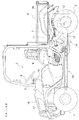
図1、図2に示される作業車の一例である多目的作業車は、荷物の運搬やレクリエーション等の多目的な用途に用いられる作業車である。多目的作業車には、操向可能且つ駆動可能な左右一対の前車輪1と、駆動可能な左右一対の後車輪2と、操縦者等が搭乗可能な運転部3と、荷物を積載可能な荷台4と、荷台4の下方に位置する原動部5等が備えられている。
〔overall structure〕
The multipurpose work vehicle which is an example of the work vehicle shown in FIGS. 1 and 2 is a work vehicle used for multipurpose applications such as luggage transportation and recreation. A multipurpose work vehicle includes a steerable and drivable pair of left and right
運転部3には、操縦者が着座する運転座席6、運転座席6に隣接して配置され、搭乗者が着座可能な補助座席7、操舵操作を行うためのステアリングホイール8、変速操作を行うための変速レバー9等が備えられている。ステアリングホイール8、及び、変速レバー9は、運転座席6の前方に位置する運転パネル10に配置されている。
The driver's
図1,2に示すように、原動部5には、ガソリンエンジン(以下、エンジンと称する)11、エンジン11の後方に位置するミッションケース12、エンジン11及びミッションケース12の左方に位置してエンジン11からミッションケース12に伝動する無段変速装置13、エンジン11に燃焼用の空気を供給する給気装置14、エンジン11からの排気を処理する排気装置15などが備えられている。
As shown in FIGS. 1 and 2, the
無段変速装置13は、周囲がケースにより覆われており、ケースの内部に図示しないベルト式無段変速機構が内装されている。無段変速装置13は、エンジン11、及び、ミッションケース12の横側部に連結支持されている。ミッションケース12は、エンジン11の後部側に連結支持されている。走行車体の前部には、開閉可能なボンネット16が備えられ、ボンネット16内に形成される空間には、エンジン11の冷却用のラジエータ17等が配置されている。
The periphery of the continuously
エンジン11は、クランク軸が機体左右方向に沿うように、且つ、シリンダヘッド18が斜め後ろ上がりとなるように、横置き姿勢で配置されている。つまり、図5,6に示すように、エンジン11のシリンダヘッド18の上面部18Aは、後方に向かうにつれて下方に位置するように後ろ下がりに傾斜している。
The
図1に示すように、走行車体には、車体の前部及び中間部を支持するメインフレーム19と、原動部5を支持する後部フレーム20とが備えられている。図3に示すように、後部フレーム20は、ダブルウィッシュボーン式の左右のリアサスペンション21を介して、左右の後車輪2を支持している。メインフレーム19は、図示しないフロントサスペンションを介して左右の前車輪1を支持している。
As shown in FIG. 1, the traveling vehicle body is provided with a
図4,5に示すように、後部フレーム20は、エンジン11を取り囲むように設けられている。図7に示すように、後部フレーム20には、前後方向に沿って延びる左右の支持フレーム22と、左右の支持フレーム22の後端部側同士を連結する横方向に延びる下部横向きフレーム23と、左右の支持フレーム22の後端部から夫々立設される縦方向に延びる後部縦向きフレーム24と、左右の後部縦向きフレーム24の上下中間位置同士を、第一ブラケット25を介して連結する横方向に延びる中間横向きフレーム26と、が備えられている。さらに、後部フレーム20には、各後部縦向きフレーム24の上端部に第二ブラケット27を介して連結される上部前後向きフレーム28、左右の上部前後向きフレーム28の前後中途部同士を連結する上部横向きフレーム29等が備えられている。
As shown in FIGS. 4 and 5, the
左右の支持フレーム22は、夫々、角パイプにより構成されている。左右の支持フレーム22は、夫々、後部側が前後方向に沿って延び、前後中途部が機体後方から前方に向かうにつれて機体外側に位置し、前部側が機体前後方向に沿って延びるように、屈曲する形状となっている。 The left and right support frames 22 are each formed by a square pipe. The left and right support frames 22 are bent so that the rear side extends in the front-rear direction, the front and rear mid-sections are located on the outer side as they go from the rear to the front, and the front side extends in the front-rear direction It has a shape.
エンジン11の動力は、無段変速装置13にて無段階に変速されたのちミッションケース12に伝達される。ミッションケース12内に備えられる図示しないギヤ式変速機構により、前進状態(前進一速状態、及び、前進二速状態)、後進状態、中立状態を、夫々、現出可能となっている。図2に示すように、ミッションケース12の動力は、後車軸31に伝達され、後車軸31から左右の後車輪2に伝達される。また、ミッションケース12の動力は、動力取出軸32、推進軸33等を介して、前車軸34に伝達され、前車軸34から左右の前車輪1に伝達可能となっている。動力取出軸32は、エンジン11の下方に位置している。
The power of the
図2に示すように、給気装置14と排気装置15とは、左右両側に振り分け配置されている。排気装置15には、エンジン11から排出される排気が通流する排気管35と、排気音を低減可能なマフラー36とが備えられている。排気管35は、エンジン11から機体前方に向けて延出されてから屈曲され、エンジン11の側方を迂回して、機体後方に向けて延出されている。排気管35は、無段変速装置13の上方を通るように配置されている。排気管35は、エンジン11の後端部から2本延出され、マフラー36の前端部で合流したのちマフラー36に接続されている。マフラー36にて排気音が低減された排気は、車体後部の排気口37から外方に排出される。
As shown in FIG. 2, the
図2に示すように、給気装置14には、エンジン11に導入される燃焼用空気が通流する給気管38、空気を除塵処理するエアークリーナ39、吸気音の消音を行うレゾネータ40、エンジン11に対する燃焼用空気の供給量を変更調節するスロットルバルブ41、給気経路をエンジン11の各気筒に分岐させる分岐部42等が備えられている。
As shown in FIG. 2, the
図3に示すように、レゾネータ40とマフラー36とは、上部横向きフレーム29、中間横向きフレーム26、左右の後部縦向きフレーム24、上部前後向きフレーム28により囲まれる空間に位置している。
As shown in FIG. 3, the
〔遮熱部材〕
図1,2に示すように、運転座席6及び補助座席7は、排気管35の前部の前斜め上方に配置されている。そこで、図5,6に示すように、運転部3と排気装置15の排気管35との間を仕切る第一遮熱部材43が備えられている。第一遮熱部材43は、排気管35の前部を覆っている。図5に示すように、第一遮熱部材43は、左右方向において排気管35よりも幅広であり、排気管35の左右幅の全域を覆う左右幅に形成されている。
[Heat shield member]
As shown in FIGS. 1 and 2, the driver's
図6に示すように、第一遮熱部材43には、排気管35の前部の前側を覆う前側部43a、前側部43aの上端部から後方に向けて延出されて排気管35の前部の上側を覆う上側部43b、及び、上側部43bの後端部から後方に向けて延出されてエンジン11のシリンダヘッド18の前部の上方を覆う延出部43cが備えられている。第一遮熱部材43は板金の曲げにより一体的に形成されている。第一遮熱部材43の後端部は、シリンダヘッド18の前後中央箇所の近傍まで延出されているとともに、後方に向かうにつれて下方に位置するように後ろ下がりに傾斜している。上側部43bは、荷台4の前端部の直下に位置するまで延出されており、第一遮熱部材43は、排気管35と運転部3との間を仕切っているとともに、荷台4と排気管35との間を仕切っている。
As shown in FIG. 6, the first
図6に示すように、第一遮熱部材43は、後部フレーム20に固定されている。第一遮熱部材43の前側部43aの左右両端部の2箇所は、夫々、上部前後向きフレーム28から横内側に向けて延びる断面L字状の第一ステー44にボルト連結されて、上部前後向きフレーム28に支持されている。また、第一遮熱部材43の上側部43bにおける第一ステー44よりも横内側の2箇所は、夫々、横内側に向けて延びる断面L字状の第二ステー45にボルト連結されて支持されている。第二ステー45は、上部前後向きフレーム28と、横方向の延びる丸パイプ状の横フレーム体46とを連結する連結部材47に支持されている。
As shown in FIG. 6, the first
図6に示すように、第一遮熱部材43の後端部とシリンダヘッド18の前部の上面部18Aとの間には、クリアランスCが設けられている。第一遮熱部材43には、このクリアランスCを埋める耐熱性及び弾性を有する遮蔽部48が備えられている。遮蔽部48は、エンジン11のシリンダヘッド18の上面部18Aの略全域を覆うように横長の形状となっている。
As shown in FIG. 6, a clearance C is provided between the rear end portion of the first
図6に示すように、遮蔽部48は、帯状に設けられた断熱材49(グラスウール)の周囲をアルミ箔50により上下両側から覆うように設けられ、且つ、その断熱材49が2つ折り状態で第一遮熱部材43の後端部を挟む状態で設けられている。遮蔽部48は、表裏両面に粘着面を有する両面接着テープ51によって第一遮熱部材43の後端部に貼り付けて固定されている。尚、折り曲げ箇所の内側にはアルミ箔50を設けないようにして折れ曲がりが円滑に行えるようにしている。
As shown in FIG. 6, the shielding
このように断熱材49(グラスウール)が外方に剥き出しにならないようにアルミ箔50により覆うことにより、断熱性を維持しながら耐久性を向上させることができる。図5に示すように、荷台4と排気管35との間には、第二遮熱部材52が備えられている。
By covering with the
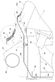
〔荷台の支持構造〕
荷台4は、荷物積載用の水平姿勢と荷物を外方に排出可能な傾斜姿勢とにわたり揺動自在に車体側固定部としての後部フレーム20に支持されている。荷台4は、車体後部側箇所に位置する横向きの軸芯X周りに揺動自在に後部フレーム20に支持され、荷物積載用の水平姿勢から前端部を上昇させて後端部側から荷を排出可能な傾斜姿勢(ダンプ状態)に姿勢変更することができる。荷台4の姿勢変更は手動で行われるが、ガススプリング55によって手動操作において操作の補助力を付与するように構成されている。
[Support structure of loading platform]
The
図9に示すように、後部フレーム20のうちの左右の上部前後向きフレーム28の後端部に、荷台4を昇降揺動可能に支持する左右のボス部56が備えられている。荷台4の後部側の下面における左右のボス部56に対応する箇所に左右の支点部材57が設けられている。左右のボス部56の夫々と左右の支点部材57の夫々とに亘って挿通する状態で左右のボルト58が設けられている。ボルト58は、左右向きの支軸として機能するものであり、荷台4がこのボルト58による横向き軸芯X周りで揺動自在に後部フレーム20に支持される。
As shown in FIG. 9, left and
図3に示すように、ガススプリング55は、レゾネータ40と右側の後部縦向きフレーム24との間に配備されている。すなわち、図7,8,9に示すように、ガススプリング55の下部は、左右の後部縦向きフレーム24のうちレゾネータ40に隣接する右側の後部縦向きフレーム24にブラケット59を介して支持されている。ブラケット59は、車体側固定部の支持部として機能するものであり、右側の後部縦向きフレーム24にボルトで連結されている。図7,8に示すように、ブラケット59は、右側の後部縦向きフレーム24の前面及び左側面にボルト連結にて固定されている。
As shown in FIG. 3, the
図7,8,9に示すように、ガススプリング55は、シリンダチューブ55Aが上側に位置し、ピストンロッド55Bが下側に位置する状態で設けられ、ピストンロッド55Bの下端部に左右向きの係止ピン60が備えられ、この係止ピン60がブラケット59に形成された挿通孔61を挿通する状態で連係されて支持されている。ブラケット59の係止ピン60が挿通する箇所は、ガススプリング55側に設けられた枢支連結部55Cを左右両側から挟むように支持する両持ち支持構造にて形成されている。
As shown in FIGS. 7, 8 and 9, the
図8に示すように、荷台4の底部にボルト連結により連結ブラケット62が取付けられ、この連結ブラケット62とガススプリング55のシリンダチューブ55Aの上端部とが左右向きの連結ピン63により、相対回動自在に枢支連結されている。荷台4の底面4Aに横方向に延びる状態で角筒状の補強部材4Bが備えられている。連結ブラケット62は、補強部材4Bに当て付けた状態でボルト連結されている。又、連結ブラケット62の連結ピン63が挿通する箇所は、ガススプリング55側に設けられた枢支連結部55Dを左右両側から挟むように支持する両持ち支持構造にて形成されている。
As shown in FIG. 8, the
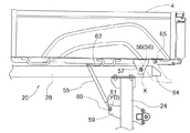
ガススプリング55とブラケット59との接続箇所に、ガススプリング55の伸長操作による補助力の付与が可能であるとともに、ガススプリング55が最伸長状態又はそれに近い状態であるときに、ガススプリング55とブラケット59との間で伸長方向に沿う設定範囲内での相対移動を許容する融通部YDが設けられている。
While it is possible to apply an auxiliary force by the extending operation of the
すなわち、図7,8に示すように、ブラケット59に形成された挿通孔61が、ガススプリング55の伸長方向すなわち上下方向に沿って長く形成された長孔に形成されている。係止ピン60は、抜け外れが阻止される状態で長孔状の挿通孔61を挿通している。係止ピン60は挿通孔61の長手方向に沿って長孔の範囲内で移動自在に設けられている。
That is, as shown in FIGS. 7 and 8, the
この構成では、係止ピン60が長孔の一端部としての挿通孔61の下端縁にて受止められた状態で、ガススプリング55の伸長操作による荷台4に対する補助力の付与が可能であり、ガススプリング55が最伸長状態又はそれに近い状態であるときに、さらに伸長する方向に向けて荷台4に外力が加わった場合に、係止ピン60が挿通孔61の長孔の範囲内で伸長方向に沿って相対移動することが可能である。
In this configuration, in the state where the locking
従って、伸長方向と交差する方向に沿って延びる状態でガススプリング55に設けられた係止ピン60と、ガススプリング55のブラケット59に形成された長孔としての挿通孔61とにより、融通部YDが構成されている。従って、ブラケット59は、車体側固定部の支持部として機能するとともに、相手側部材として機能するものである。
Therefore, the flexible portion YD is formed by the locking
又、荷台4の揺動に伴って、係止ピン60が長孔の一端部としての挿通孔61の下端縁から伸長方向に沿って移動して長孔の他端部としての挿通孔61の上端縁に至るまでの中間位置にあるときに、車体フレームSの受止め部64に接当してそれ以上の揺動を規制する接当規制部65が、荷台4に設けられている。
The locking
すなわち、図9に示すように、右側の上部前後向きフレーム28の後端部から後下方に向けて延びる状態で受止め部64が延設されている。荷台4が傾斜姿勢に切り換えられ、ガススプリング55が最伸長状態に至ったのちも、伸長する方向に向けて荷台4に外力が加わり、係止ピン60が挿通孔61の中間位置に至ると、図10に示すように、荷台4側の接当規制部65が受止め部64に接当してそれ以上の揺動が規制される。このように荷台4が揺動規制されることにより、ガススプリング55に対して伸長方向に無理な力が掛かることがなく、ガススプリング55が損傷するおそれが少なくなる。
That is, as shown in FIG. 9, the receiving
〔別実施形態〕
(1)上記実施形態では、ガススプリング55とブラケット59(車体側固定部の支持部)との接続箇所に融通部YDが設けられる構成としたが、この構成に代えて、ガススプリング55と荷台4との接続箇所に融通部YDを設ける構成としてもよく、ガススプリング55とブラケット59との接続箇所と、ガススプリング55と荷台4との接続箇所との夫々に、融通部YDを設ける構成としてもよい。
[Another embodiment]
(1) In the above embodiment, the flexible portion YD is provided at the connection point between the
(2)上記実施形態では、融通部YDとして、ガススプリング55に係止ピン60が設けられ、相手側部材(ブラケット59)に長孔(挿通孔)61が形成される構成としたが、この構成に代えて、ガススプリング55に長孔(挿通孔)が設けられ、相手側部材(ブラケット59)に係止ピン60が設けられる構成としてもよい。又、係止ピンと長孔とにより融通部YDを構成するものに代えて、他の型式の融通構造、例えば、融通用のコイルバネを介在して構成されるもの等でもよい。
(2) In the above embodiment, the
(3)上記実施形態では、後部フレーム20(車体側固定部)の受止め部64に接当して揺動を規制する接当規制部65が、荷台4に設けられる構成としたが、このような受止め部64及び接当規制部65を備えない構成としてもよい。
(3) In the above-described embodiment, the
(4)上記実施形態では、作業車として多目的作業車を例に説明したが、多目的作業車に限らず、本発明は、荷台を備える種々の型式の作業車に適用できる。 (4) In the above embodiment, a multipurpose work vehicle is described as an example of a work vehicle, but the invention is not limited to the multipurpose work vehicle, and the present invention can be applied to various types of work vehicles equipped with a loading platform.
本発明は、揺動自在に支持された荷台を手動で揺動操作する際に、補助力を付与するガススプリングが備えられている作業車に適用できる。 The present invention can be applied to a working vehicle provided with a gas spring that applies an assisting force when manually swinging a swingably supported platform.
4 荷台
20 車体側固定部
55 ガススプリング
59 支持部(相手側部材)
60 係止ピン
61 長孔
64 受止め部
65 接当規制部
YD 融通部
4
60
Claims (3)
前記荷台の姿勢変更に伴う揺動作用箇所と前記車体側固定部の支持部とにわたって設けられ、前記荷台の前記水平姿勢から前記傾斜姿勢への姿勢切り換えの際に補助力を付与するガススプリングとが備えられ、
前記ガススプリングと前記荷台との接続箇所、及び、前記ガススプリングと前記支持部との接続箇所のうちの少なくともいずれか一方に、前記ガススプリングの伸長操作による前記補助力の付与が可能であるとともに、前記ガススプリングが最伸長状態又はそれに近い状態であるときに、前記ガススプリングと前記荷台との間又は前記ガススプリングと前記支持部との間で伸長方向に沿う設定範囲内での相対移動を許容する融通部が設けられている作業車。 A loading platform supported on the vehicle-side fixed portion so as to freely swing between a horizontal position for loading a load and an inclined position capable of discharging the load outward;
A gas spring which is provided across the swing action portion accompanying the posture change of the loading platform and the support portion of the vehicle-body-side fixing unit, and applies an assisting force at the time of the posture switching from the horizontal orientation of the loading platform to the inclined orientation; Is equipped with
The auxiliary force can be applied by the extending operation of the gas spring to at least one of the connection point between the gas spring and the loading platform and the connection point between the gas spring and the support portion. When the gas spring is at or near the maximum extension state, relative movement within a set range along the extension direction between the gas spring and the bed or between the gas spring and the support portion A working vehicle provided with an acceptable interchange.
前記ガススプリング及び相手側部材のうちのいずれか一方に、前記伸長方向と交差する方向に沿って延びる状態で設けられた係止ピンと、
前記ガススプリング及び相手側部材のうちの他方に、前記係止ピンが嵌り合い係合する状態で前記伸長方向に沿って長く形成された長孔とを備え、且つ、
前記係止ピンが前記長孔の一端部にて受止められた状態で、前記ガススプリングの伸長操作による前記補助力の付与が可能であり、前記係止ピンが前記長孔の範囲内で前記伸長方向に沿う移動が許容されるように構成されている請求項1に記載の作業車。 The flexible section
A locking pin provided on any one of the gas spring and the counterpart member so as to extend along a direction intersecting the extending direction;
The other of the gas spring and the other member is provided with an elongated hole formed along the extending direction in a state in which the locking pin is engaged with each other, and
In the state where the locking pin is received at one end of the long hole, the auxiliary force can be applied by the extending operation of the gas spring, and the locking pin is within the range of the long hole. The work vehicle according to claim 1, wherein movement along the extension direction is allowed.
Priority Applications (1)
| Application Number | Priority Date | Filing Date | Title |
|---|---|---|---|
| JP2017186231A JP6815301B2 (en) | 2017-09-27 | 2017-09-27 | Work vehicle |
Applications Claiming Priority (1)
| Application Number | Priority Date | Filing Date | Title |
|---|---|---|---|
| JP2017186231A JP6815301B2 (en) | 2017-09-27 | 2017-09-27 | Work vehicle |
Publications (2)
| Publication Number | Publication Date |
|---|---|
| JP2019059372A true JP2019059372A (en) | 2019-04-18 |
| JP6815301B2 JP6815301B2 (en) | 2021-01-20 |
Family
ID=66178305
Family Applications (1)
| Application Number | Title | Priority Date | Filing Date |
|---|---|---|---|
| JP2017186231A Active JP6815301B2 (en) | 2017-09-27 | 2017-09-27 | Work vehicle |
Country Status (1)
| Country | Link |
|---|---|
| JP (1) | JP6815301B2 (en) |
Cited By (2)
| Publication number | Priority date | Publication date | Assignee | Title |
|---|---|---|---|---|
| CN117183869A (en) * | 2023-10-27 | 2023-12-08 | 河南跃薪时代新能源科技有限公司 | A kind of dump truck compartment rear door locking mechanism |
| US12151743B2 (en) | 2022-03-16 | 2024-11-26 | Kubota Corporation | Work vehicle |
-
2017
- 2017-09-27 JP JP2017186231A patent/JP6815301B2/en active Active
Cited By (2)
| Publication number | Priority date | Publication date | Assignee | Title |
|---|---|---|---|---|
| US12151743B2 (en) | 2022-03-16 | 2024-11-26 | Kubota Corporation | Work vehicle |
| CN117183869A (en) * | 2023-10-27 | 2023-12-08 | 河南跃薪时代新能源科技有限公司 | A kind of dump truck compartment rear door locking mechanism |
Also Published As
| Publication number | Publication date |
|---|---|
| JP6815301B2 (en) | 2021-01-20 |
Similar Documents
| Publication | Publication Date | Title |
|---|---|---|
| US8887859B2 (en) | Brake pipe structure of motorcycle | |
| JP4606290B2 (en) | Vehicle suspension structure | |
| CN109843612B (en) | Rear suspension components for off-road vehicles | |
| JP2003127629A (en) | Rear wheel suspension system for saddle-ride type vehicles | |
| JP4627370B2 (en) | Body frame structure for motorcycles | |
| JP2019059372A (en) | Work vehicle | |
| JP3003485B2 (en) | Motor unit support structure for electric vehicles | |
| JP4467054B2 (en) | Vehicle body frame structure | |
| US20070095624A1 (en) | Saddle-type vehicle and steering damper for use in the same | |
| JP4459161B2 (en) | Scooter type vehicle frame structure | |
| JP5088088B2 (en) | Scooter-type vehicle intake system | |
| JP6655970B2 (en) | Multipurpose vehicle | |
| US20200164707A1 (en) | Vehicle | |
| JP2008080882A (en) | Front wheel suspension | |
| JP4601117B2 (en) | Connection structure of vehicle body components in a vehicle | |
| JPH02109727A (en) | Driving device for vehicle running on rough terrain | |
| JP4376042B2 (en) | Body frame structure | |
| US20260048801A1 (en) | Saddle bag support assembly for a vehicle and vehicle having the same | |
| JP3611711B2 (en) | Car parking brake cable routing structure | |
| JP2513688Y2 (en) | Vehicle with horizontal engine | |
| JP2000016337A (en) | Arrangement structure of rear suspension | |
| JP6868947B2 (en) | Vehicle structure | |
| JP2008222136A (en) | Sidecar body structure | |
| WO2023037377A1 (en) | A vehicle | |
| JPH1179041A (en) | Saddle-type four-wheeled vehicle |
Legal Events
| Date | Code | Title | Description |
|---|---|---|---|
| A621 | Written request for application examination |
Free format text: JAPANESE INTERMEDIATE CODE: A621 Effective date: 20191225 |
|
| A977 | Report on retrieval |
Free format text: JAPANESE INTERMEDIATE CODE: A971007 Effective date: 20200806 |
|
| A131 | Notification of reasons for refusal |
Free format text: JAPANESE INTERMEDIATE CODE: A131 Effective date: 20200908 |
|
| A521 | Written amendment |
Free format text: JAPANESE INTERMEDIATE CODE: A523 Effective date: 20201102 |
|
| TRDD | Decision of grant or rejection written | ||
| A01 | Written decision to grant a patent or to grant a registration (utility model) |
Free format text: JAPANESE INTERMEDIATE CODE: A01 Effective date: 20201124 |
|
| A61 | First payment of annual fees (during grant procedure) |
Free format text: JAPANESE INTERMEDIATE CODE: A61 Effective date: 20201222 |
|
| R150 | Certificate of patent or registration of utility model |
Ref document number: 6815301 Country of ref document: JP Free format text: JAPANESE INTERMEDIATE CODE: R150 |