JP2020005389A - Power supply system - Google Patents
Power supply system Download PDFInfo
- Publication number
- JP2020005389A JP2020005389A JP2018122316A JP2018122316A JP2020005389A JP 2020005389 A JP2020005389 A JP 2020005389A JP 2018122316 A JP2018122316 A JP 2018122316A JP 2018122316 A JP2018122316 A JP 2018122316A JP 2020005389 A JP2020005389 A JP 2020005389A
- Authority
- JP
- Japan
- Prior art keywords
- voltage
- storage unit
- power storage
- battery
- inverter
- Prior art date
- Legal status (The legal status is an assumption and is not a legal conclusion. Google has not performed a legal analysis and makes no representation as to the accuracy of the status listed.)
- Granted
Links
Images



Classifications
-
- Y—GENERAL TAGGING OF NEW TECHNOLOGICAL DEVELOPMENTS; GENERAL TAGGING OF CROSS-SECTIONAL TECHNOLOGIES SPANNING OVER SEVERAL SECTIONS OF THE IPC; TECHNICAL SUBJECTS COVERED BY FORMER USPC CROSS-REFERENCE ART COLLECTIONS [XRACs] AND DIGESTS
- Y02—TECHNOLOGIES OR APPLICATIONS FOR MITIGATION OR ADAPTATION AGAINST CLIMATE CHANGE
- Y02E—REDUCTION OF GREENHOUSE GAS [GHG] EMISSIONS, RELATED TO ENERGY GENERATION, TRANSMISSION OR DISTRIBUTION
- Y02E60/00—Enabling technologies; Technologies with a potential or indirect contribution to GHG emissions mitigation
- Y02E60/10—Energy storage using batteries
-
- Y—GENERAL TAGGING OF NEW TECHNOLOGICAL DEVELOPMENTS; GENERAL TAGGING OF CROSS-SECTIONAL TECHNOLOGIES SPANNING OVER SEVERAL SECTIONS OF THE IPC; TECHNICAL SUBJECTS COVERED BY FORMER USPC CROSS-REFERENCE ART COLLECTIONS [XRACs] AND DIGESTS
- Y02—TECHNOLOGIES OR APPLICATIONS FOR MITIGATION OR ADAPTATION AGAINST CLIMATE CHANGE
- Y02T—CLIMATE CHANGE MITIGATION TECHNOLOGIES RELATED TO TRANSPORTATION
- Y02T10/00—Road transport of goods or passengers
- Y02T10/60—Other road transportation technologies with climate change mitigation effect
- Y02T10/70—Energy storage systems for electromobility, e.g. batteries
-
- Y—GENERAL TAGGING OF NEW TECHNOLOGICAL DEVELOPMENTS; GENERAL TAGGING OF CROSS-SECTIONAL TECHNOLOGIES SPANNING OVER SEVERAL SECTIONS OF THE IPC; TECHNICAL SUBJECTS COVERED BY FORMER USPC CROSS-REFERENCE ART COLLECTIONS [XRACs] AND DIGESTS
- Y02—TECHNOLOGIES OR APPLICATIONS FOR MITIGATION OR ADAPTATION AGAINST CLIMATE CHANGE
- Y02T—CLIMATE CHANGE MITIGATION TECHNOLOGIES RELATED TO TRANSPORTATION
- Y02T10/00—Road transport of goods or passengers
- Y02T10/60—Other road transportation technologies with climate change mitigation effect
- Y02T10/7072—Electromobility specific charging systems or methods for batteries, ultracapacitors, supercapacitors or double-layer capacitors
-
- Y—GENERAL TAGGING OF NEW TECHNOLOGICAL DEVELOPMENTS; GENERAL TAGGING OF CROSS-SECTIONAL TECHNOLOGIES SPANNING OVER SEVERAL SECTIONS OF THE IPC; TECHNICAL SUBJECTS COVERED BY FORMER USPC CROSS-REFERENCE ART COLLECTIONS [XRACs] AND DIGESTS
- Y02—TECHNOLOGIES OR APPLICATIONS FOR MITIGATION OR ADAPTATION AGAINST CLIMATE CHANGE
- Y02T—CLIMATE CHANGE MITIGATION TECHNOLOGIES RELATED TO TRANSPORTATION
- Y02T90/00—Enabling technologies or technologies with a potential or indirect contribution to GHG emissions mitigation
- Y02T90/10—Technologies relating to charging of electric vehicles
- Y02T90/14—Plug-in electric vehicles
Landscapes
- Charge And Discharge Circuits For Batteries Or The Like (AREA)
- Secondary Cells (AREA)
- Electric Propulsion And Braking For Vehicles (AREA)
- Inverter Devices (AREA)
Abstract
【課題】並列充電時の過電流を回避可能な電源システムを提供する。【解決手段】並列リレー93、94は、充電器100、第1バッテリ11および第1コンデンサ69と、第2バッテリ21および第2コンデンサ79との断接を切り替え可能である。制御部30は、充電器100による充電を行っていない場合、第1バッテリ電圧V1が第2バッテリ電圧V2以下となるように、第1バッテリ11および第2バッテリ21の充電量を制御する。また制御部30は、充電器100による充電を行う場合、第1バッテリ電圧V1と第2バッテリ電圧V2との電圧差ΔVが電圧判定閾値Vth以上である場合、並列リレー93、94を開とし、第1バッテリ11を片側充電し、電圧差ΔVが電圧判定閾値Vthより小さい場合、並列リレー93、94を閉とし、第1バッテリ11および第2バッテリ21を並列充電する。【選択図】 図1PROBLEM TO BE SOLVED: To provide a power supply system capable of avoiding overcurrent during parallel charging. SOLUTION: Parallel relays 93, 94 can switch connection/disconnection between a charger 100, a first battery 11 and a first capacitor 69, and a second battery 21 and a second capacitor 79. The control unit 30 controls the charge amounts of the first battery 11 and the second battery 21 so that the first battery voltage V1 is equal to or lower than the second battery voltage V2 when the charger 100 is not charging the battery. Further, when charging by the charger 100, the control unit 30 opens the parallel relays 93 and 94 when the voltage difference ΔV between the first battery voltage V1 and the second battery voltage V2 is the voltage determination threshold Vth or more, When the first battery 11 is charged on one side and the voltage difference ΔV is smaller than the voltage determination threshold value Vth, the parallel relays 93 and 94 are closed and the first battery 11 and the second battery 21 are charged in parallel. [Selection diagram]
Description
本発明は、電源システムに関する。 The present invention relates to a power supply system.
従来、車両外部からの電力によって複数の電池を充電する充電装置が知られている。例えば特許文献1では、電圧が高い方の電池の電力エネルギを、外部コンデンサを介して電圧が低い方の電池に移動させ、電圧を均等化している。 Conventionally, a charging device that charges a plurality of batteries with electric power from the outside of a vehicle has been known. For example, in Patent Literature 1, the power energy of a battery with a higher voltage is transferred to a battery with a lower voltage via an external capacitor to equalize the voltage.
ところで、例えば、2つの電圧源がモータのオープン巻線の両端にインバータを介して接続されている「2電源2インバータ」の構成において、インバータに平滑コンデンサが接続されていることがある。当該構成において、特許文献1のように、外部コンデンサを用いて電圧を揃えようとすると、外部コンデンサと接続した瞬間に外部コンデンサと平滑コンデンサとの間に突入電流が流れ、外部コンデンサとの断接を切り替えるリレーやコンデンサが損傷する虞がある。 By the way, for example, in a configuration of “two power supplies and two inverters” in which two voltage sources are connected to both ends of an open winding of a motor via an inverter, a smoothing capacitor may be connected to the inverter. In this configuration, if the voltage is to be adjusted using an external capacitor as in Patent Document 1, an inrush current flows between the external capacitor and the smoothing capacitor at the moment of connection with the external capacitor, and the connection and disconnection with the external capacitor are performed. There is a possibility that a relay or a capacitor that switches between them may be damaged.
本発明は、上述の課題に鑑みてなされたものであり、その目的は、並列充電時の過電流を回避可能な電源システムを提供することにある。 The present invention has been made in view of the above-described problems, and an object of the present invention is to provide a power supply system capable of avoiding an overcurrent at the time of parallel charging.
本発明の電源システムは、第1蓄電部(11)と、第2蓄電部(21)と、第1コンデンサ(69)と、第2コンデンサ(79)と、開閉器(93、94)と、第1電圧検出部(15)と、第2電圧検出部(25)と、制御部(30)と、を備える。 The power supply system of the present invention includes a first power storage unit (11), a second power storage unit (21), a first capacitor (69), a second capacitor (79), a switch (93, 94), A first voltage detector (15), a second voltage detector (25), and a controller (30) are provided.
第1蓄電部は、充電器(100)からの電力により充電可能である。第2蓄電部は、充電器からの電力により第1蓄電部と並列に充電可能である。第1コンデンサは、第1蓄電部と並列に接続される。第2コンデンサは、第2蓄電部と並列に接続される。開閉器は、充電器、第1蓄電部および第1コンデンサと、第2蓄電部および第2コンデンサとの断接を切り替え可能である。第1電圧検出部は、第1蓄電部の電圧である第1蓄電部電圧を検出する。第2電圧検出部は、第2蓄電部の電圧である第2蓄電部電圧を検出する。 The first power storage unit is chargeable by electric power from the charger (100). The second power storage unit can be charged in parallel with the first power storage unit by the power from the charger. The first capacitor is connected in parallel with the first power storage unit. The second capacitor is connected in parallel with the second power storage unit. The switch can switch connection / disconnection between the charger, the first power storage unit and the first capacitor, and the second power storage unit and the second capacitor. The first voltage detector detects a first power storage unit voltage that is a voltage of the first power storage unit. The second voltage detection unit detects a second power storage unit voltage that is a voltage of the second power storage unit.
制御部は、第1蓄電部電圧および第2蓄電部電圧に基づき、第1蓄電部および第2蓄電部の充電量を制御する。制御部は、充電器による充電を行っていない場合、第1蓄電部電圧が第2蓄電部電圧以下となるように、第1蓄電部および第2蓄電部の充電量を制御する。また、制御部は、充電器による充電を行う場合、第1蓄電部電圧と第2蓄電部電圧との電圧差が電圧判定閾値以上である場合、リレーを開とし、第1蓄電部を片側充電し、電圧差が電圧判定閾値より小さい場合、リレーを閉とし、第1蓄電部および第2蓄電部を並列充電する。これにより、並列充電時の過電流を回避することができる。 The control unit controls the charge amounts of the first power storage unit and the second power storage unit based on the first power storage unit voltage and the second power storage unit voltage. The control unit controls the charge amounts of the first power storage unit and the second power storage unit such that the first power storage unit voltage is equal to or lower than the second power storage unit voltage when the charging by the charger is not performed. Further, when performing charging by the charger, the control unit opens the relay when the voltage difference between the first power storage unit voltage and the second power storage unit voltage is equal to or greater than the voltage determination threshold, and charges the first power storage unit to one-sided charging. If the voltage difference is smaller than the voltage determination threshold, the relay is closed, and the first power storage unit and the second power storage unit are charged in parallel. Thereby, an overcurrent at the time of parallel charging can be avoided.
(一実施形態)
以下、電源システムを図面に基づいて説明する。図1に示すように、電源システム1は、車両98に搭載される。車両98は、例えば電気自動車やハイブリッド車両等の電動車両である。車両98には、インレット99が設けられる。インレット99は、充電器100の充電器コネクタ115と接続可能であり、インレット99と充電器コネクタ115とを接続することで、電源システム1には、充電器100から給電される。
(One embodiment)
Hereinafter, the power supply system will be described with reference to the drawings. As shown in FIG. 1, the power supply system 1 is mounted on a
充電器100は、例えば急速充電器であって、電力供給部101、リレー102、103、および、充電器コネクタ115を有する。電力供給部101は、図示しない商用電源等から供給される交流電力を直流電力に変換し、直流電力を、リレー102、103、ケーブル116および充電器コネクタ115を経由して、車両98に供給する。
The
電源システム1は、バッテリ11、21、メインリレー12、13、22、23、電圧検出部15、25、制御部30、第1インバータ60、第2インバータ70、コンデンサ69、79、回転電機としてのモータジェネレータ80、並列リレー93、94等を備える。以下適宜、モータジェネレータを「MG」と記載する。
The power supply system 1 includes
第1バッテリ11は、第1インバータ60と接続され、第1インバータ60を経由してMG80と電力を授受可能に設けられる。第2バッテリ21は、第2インバータ70と接続され、第2インバータ70を経由してMG80と電力を授受可能に設けられる。バッテリ11、21は、充電器100にて充電可能に設けられる。バッテリ11、21の充電方法の詳細は、後述する。
First battery 11 is connected to
メインリレー12は第1バッテリ11の高電位側に設けられ、メインリレー13は第1バッテリ11の低電位側に設けられる。メインリレー22は第2バッテリ21の高電位側に設けられ、メインリレー23は第2バッテリ21の低電位側に設けられる。
The
電圧検出部15は、第1バッテリ11の電圧である第1バッテリ電圧V1を検出する。電圧検出部25は、第2バッテリ21の電圧である第2バッテリ電圧V2を検出する。電圧検出部15、25の検出値は、制御部30に出力される。
The
MG80は、例えば永久磁石式同期型の3相交流モータであって、U相コイル81、V相コイル82、および、W相コイル83を有する。MG80は、図示しない駆動輪を駆動するためのトルクを発生する、いわゆる主機モータであり、駆動輪を駆動するための電動機としての機能、および、図示しないエンジンや駆動輪から伝わる運動エネルギによって駆動されて発電する発電機としての機能を有する。
The MG 80 is, for example, a permanent magnet synchronous type three-phase AC motor, and includes a
MG80には、第1バッテリ11および第2バッテリ21から電力が供給される。第1バッテリ11と第2バッテリ21とは、絶縁されている。バッテリ11、21は、ニッケル水素電池、リチウムイオン電池等の充放電可能な蓄電装置である。二次電池に替えて、電気二重層キャパシタ等を用いてもよい。本実施形態では、バッテリ11、21は、同電圧、同容量であって同等の性能とするが、例えば一方に出力型のものを用い、他方に容量型のものを用いる、といった具合に、電池性能が異なっていてもよい。本実施形態では、バッテリ11、21の定格電圧が異なる場合、定格電圧が小さいものを第1バッテリ11とし、定格電圧が大きいものを第2バッテリ21とする。第1バッテリ11に流すことのできる最大電流を許容電流Ilim1、第2バッテリ21に流すことのできる最大電流を許容電流Ilim2とする。
MG 80 is supplied with power from first battery 11 and
第1インバータ60は、コイル81〜83の通電を切り替える3相インバータであって、スイッチング素子61〜66を有し、第1バッテリ11およびMG80に接続される。第2インバータ70は、コイル81〜83の通電を切り替える3相インバータであって、スイッチング素子71〜76を有し、第2バッテリ21およびMG80に接続される。
スイッチング素子61〜66、71〜76は、それぞれ、スイッチ部および還流ダイオードを有する。スイッチ部は、制御部30によりオンオフ作動が制御される。本実施形態では、スイッチ部はIGBTであるが、MOSFET等、他の素子を用いてもよい。また、第1スイッチング素子61〜66と第2スイッチング素子71〜76とで、用いる素子の種類が異なっていてもよい。
Each of the
還流ダイオードは、各スイッチ部と並列に接続され、低電位側から高電位側への通電を許容する。還流ダイオードは、例えばMOSFETの寄生ダイオードのように内蔵されていてもよいし、外付けされたものであってもよい。また、還流できるように接続されたIGBTやMOSFET等のスイッチであってもよい。 The freewheeling diode is connected in parallel with each switch unit, and allows current to flow from the low potential side to the high potential side. The freewheeling diode may be built-in, for example, like a parasitic diode of a MOSFET, or may be externally attached. Further, a switch such as an IGBT or a MOSFET connected so as to be able to return may be used.
第1インバータ60において、高電位側にスイッチング素子61〜63が接続され、低電位側にスイッチング素子64〜66が接続される。以下適宜、高電位側のスイッチング素子61〜63を「第1上アーム素子」、低電位側のスイッチング素子64〜66を「第1下アーム素子」とする。第1上アーム素子61〜63の高電位側を接続する第1高電位側配線111が第1バッテリ11の正極と接続され、第1下アーム素子64〜66の低電位側を接続する第1低電位側配線112が第1バッテリ11の負極と接続される。
In the
U相のスイッチング素子61、64の接続点にはU相コイル81の一端811が接続され、V相のスイッチング素子62、65の接続点にはV相コイル82の一端821が接続され、W相のスイッチング素子63、66の接続点にはW相コイル83の一端831が接続される。
One end 811 of the
第2インバータ70において、高電位側にスイッチング素子71〜73が接続され、低電位側にスイッチング素子74〜76が接続される。以下適宜、高電位側のスイッチング素子71〜73を「第2上アーム素子」、低電位側のスイッチング素子74〜76を「第2下アーム素子」とする。第2上アーム素子71〜73の高電位側を接続する第2高電位側配線121が第2バッテリ21の正極と接続され、第2下アーム素子74〜76の低電位側を接続する第2低電位側配線122が第2バッテリ21の負極と接続される。
In the
U相のスイッチング素子71、74の接続点にはU相コイル81の他端812が接続され、V相のスイッチング素子72、75の接続点にはV相コイル82の他端822が接続され、W相のスイッチング素子73、76の接続点にはW相コイル83の他端832が接続される。
The
このように、本実施形態では、MG80のコイル81〜83は、オープン巻線化されており、第1インバータ60および第2インバータ70が、コイル81〜83の両側に接続されてる「2電源2インバータ」の電動機駆動システムとなっている。
As described above, in the present embodiment, the
第1高電位側配線111と第2高電位側配線121とは、高電位側接続線91にて接続される。第1低電位側配線112と第2低電位側配線122とは、低電位側接続線92にて接続される。
The first high
第1コンデンサ69は、高電位側配線111と低電位側配線112とに接続され、第1インバータ60と並列に設けられる。第2コンデンサ79は、高電位側配線121と低電位側配線122とに接続され、第2インバータ70と並列に設けられる。コンデンサ69、79は、平滑コンデンサであって、インバータ60、70に印加される電圧を平滑化する。
The
本実施形態では、第1バッテリ11側に充電器100が設けられる。詳細には、第1高電位側配線111および第1低電位側配線112が、インレット99に接続されている。高電位側接続線91には高電位側並列リレー93が設けられ、低電位側接続線92には低電位側並列リレー94が設けられる。高電位側並列リレー93を閉とすることで高電位側配線111、121が接続され、低電位側並列リレー94を閉とすることで低電位側配線112、122が接続される。並列リレー93、94を閉とすることで、バッテリ11、21が並列接続され、充電器100からの電力を第2バッテリ21側へ供給可能となる。
In the present embodiment, the
以下適宜、並列リレー93、94を介さずに充電器100と接続される第1バッテリ11を「充電器100と直接的に接続されている」とし、並列リレー93、94を介して充電器100と接続される第2バッテリ21を「充電器100と間接的に接続されている」とする。
Hereinafter, the first battery 11 connected to the
制御部30は、マイコン等を主体として構成され、内部にはいずれもCPU、ROM、RAM、I/O、及び、これらの構成を接続するバスライン等を備えている。制御部30における各処理は、ROM等の実体的なメモリ装置(すなわち、読み出し可能非一時的有形記録媒体)に予め記憶されたプログラムをCPUで実行することによるソフトウェア処理であってもよいし、例えばFPGA(field-programmable gate array)のような電子回路によるハードウェア処理であってもよい。
The
制御部30は、インバータ制御部31、リレー制御部32、および、充電量制御部33等を有する。インバータ制御部31、リレー制御部32、および、充電量制御部33は、1つのマイコンにて構成されていてもよいし、別途のマイコンにて構成されていてもよい。また、第1インバータ60を制御するマイコンと第2インバータ70を制御するマイコンとが別途に設けられていてもよい。
The
インバータ制御部31は、スイッチング素子61〜66、71〜76のオンオフ作動を制御する。第1インバータ60の駆動制御に係る制御信号は、ドライブ回路36を経由して第1インバータ60に出力される。第2インバータ70の駆動制御に係る制御信号は、ドライブ回路37を経由して第2インバータ70に出力される。リレー制御部32は、メインリレー12、13、22、23、および、並列リレー93、94の開閉作動を制御する。なお、メインリレー12、13、22、23は、例えば、車両98の全体の制御を司る上位制御部を構成するマイコンにより開閉が制御されるようにしてもよい。
The
充電量制御部33は、バッテリ11、21の充電に係る充電電流指令値Ic*を演算し、バッテリ11、21の充電を制御する。充電電流指令値Ic*は、通信等にて、充電器100に送信される。これにより、充電電流指令値Ic*に応じた電力が充電器100から電源システム1に供給される。
The charge
インバータ制御部31は、例えば第1基本波F1とキャリア波とに基づいて第1インバータ60を制御し、第2基本波F2とキャリア波とに基づいて第2インバータ70を制御する。基本波F1、F2に応じた制御には、基本波F1、F2の振幅がキャリア波の振幅以下である、すなわち変調率が1以下である正弦波PWM制御や、基本波F1、F2の振幅がキャリア波の振幅より大きい、すなわち変調率が1より大きい過変調PWM制御が含まれる。また、基本波F1、F2の振幅を無限大とみなし、基本波F1、F2の半周期ごとに各素子のオンオフが切り替えられる矩形波制御としてもよい。矩形波制御は、電気角の180°ごとに各素子のオンオフを切り替える180°通電制御と捉えることもできる。また、矩形波制御において、例えば120°通電等、通電位相は180°以外であってもよい。
The
ここで、MG80の駆動モードを説明する。本実施形態では、MG80の駆動に、第1バッテリ11または第2バッテリ21の電力を用いる「片側駆動モード」、第1バッテリ11および第2バッテリ21の電力を用いる「両側駆動モード」が含まれる。図2は、横軸をMG回転数N、縦軸をMGトルクtrqとした動作点マップであり、破線Lより低負荷側を片側駆動領域、破線Lより高負荷側を両側駆動領域とする。ここでは、動作点に応じた駆動領域を、便宜上、「片側駆動領域」、「両側駆動領域」とするが、運転条件等に応じ、片側駆動領域において、両側駆動を行ってもよい。
Here, the drive mode of
片側駆動モードでは、第1バッテリ11の電力にてMG80を駆動する場合、第2インバータ70の上アーム素子71〜73の全相、または、下アーム素子74〜76の全相の一方をオン、他方をオフとし、第2インバータ70を中性点化する。また、MG80の駆動要求に応じ、PWM制御や矩形波制御等により、第1インバータ60を制御する。
In the one-side drive mode, when the
また、第2バッテリ21の電力にてMG80を駆動する場合、第1インバータ60の上アーム素子61〜63の全相、または、下アーム素子64〜66の全相の一方をオン、他方をオフとし、第1インバータ60を中性点化する。また、MG80の駆動要求に応じ、PWM制御や矩形波制御等により、第2インバータ70を制御する。
When
両側駆動モードでは、第1基本波F1と第2基本波F2の位相が反転される。換言すると、第1基本波F1と第2基本波F2とは、位相が略180[°]ずれている。第1基本波F1と第2基本波F2との位相差を180[°]とすることで、第1バッテリ11と第2バッテリ21とが電気的に直列接続されている状態とみなすことができ、第1バッテリ11の電圧と第2バッテリ21の電圧との和に相当する電圧をMG80に印加可能である。なお、第1基本波F1と第2基本波F2との位相差は、180[°]とするが、第1バッテリ11の電圧および第2バッテリ21の電圧の和に相当する電圧をMG80に印加可能な程度のずれは許容されるものとする。
In the both-side drive mode, the phases of the first fundamental wave F1 and the second fundamental wave F2 are inverted. In other words, the phases of the first fundamental wave F1 and the second fundamental wave F2 are shifted by approximately 180 [°]. By setting the phase difference between the first fundamental wave F1 and the second fundamental wave F2 to 180 [°], it can be considered that the first battery 11 and the
ところで、本実施形態では、バッテリ11、21を、1つの充電器100により充電する。絶縁された2つのバッテリ11、21を並列充電する場合、電圧差があると、電圧差に応じた電流がバッテリ11、21間で流れるため、充電器100から投入できる電流が減少し、充電時間が長くなる。参考例として、外部コンデンサを用いて電圧の高い方から低い方へと電力を受け渡すことで、電圧差を解消することが考えられる。
By the way, in the present embodiment, the
しかしながら、本実施形態のように、2電源2インバータの構成の場合、電源システム1と外部コンデンサとを接続した瞬間に、インバータ60、70に接続されているコンデンサ69、79と、外部コンデンサとの間で大きなパルス電流が流れるため、開閉器やコンデンサ69、79が損傷する虞がある。一般に、コンデンサ69、79の内部インピーダンスは、バッテリ11、21の内部インピーダンスよりも小さいため、バッテリ11、21と外部コンデンサとの間のパルス電流よりも、コンデンサ69、79と外部コンデンサとの間のパルス電流の方が大きくなる蓋然性が高い。そのため、参考例のように、外部コンデンサを用いてバッテリ11、21の電圧を揃える場合、コンデンサ69、79と外部コンデンサとを切り離すための開閉器を追加で設ける必要があり、部品点数が増大する。
However, in the case of the configuration of the two power supplies and two inverters as in the present embodiment, at the moment when the power supply system 1 and the external capacitors are connected, the
そこで本実施形態では、外部コンデンサを用いずに、充電器100からバッテリ11、21の並列充電を実現する。具体的には、充電器100に接続されている側の第1バッテリ11の電圧である第1バッテリ電圧V1が、充電器100に接続されていない側の第2バッテリ21の電圧である第2バッテリ電圧V2よりも常時低くなるようにしておく。本実施形態では、片側駆動モードにおいて、力行時、第2インバータ70を中性点化することで第1バッテリ11の電力を優先的に用い、回生時、第1インバータ60を中性点化することで第2バッテリ21を優先的に充電することで、V1<V2の関係を維持する。
Therefore, in the present embodiment, parallel charging of the
そして、並列充電を行う前に、並列リレー93、94を開とし、低電圧となっている第1バッテリ11の片側充電を行うことで第1バッテリ電圧V1を高める。第1バッテリ電圧V1の上昇により、バッテリ11、21の電圧差が許容範囲内になった場合、並列リレー93、94を閉とし、並列充電に移行する。例えば、バッテリ電圧V1、V2の電圧差ΔVが、並列充電可能な電圧判定閾値Vthより小さくなった場合、並列リレー93、94を閉とし、並列充電に移行する。以下適宜、バッテリ電圧V1、V2の差の絶対値を電圧差ΔVとする。
Then, before performing the parallel charging, the
本実施形態の駆動制御処理を図3のフローチャートに基づいて説明する。この処理は、インバータ制御部31にて、駆動モードとして片側駆動モードが選択されている場合に、所定の周期で実行される。以下、ステップS101の「ステップ」を省略し、単に記号「S」と記す。他のステップも同様である。図中、第1バッテリ11を「バッテリ1」、第2バッテリ21を「バッテリ2」と記載した。
The drive control processing according to the present embodiment will be described with reference to the flowchart in FIG. This process is executed at a predetermined cycle when the
S101では、インバータ制御部31は、バッテリ電圧V1、V2を取得する。S102では、インバータ制御部31は、第1バッテリ電圧V1から第2バッテリ電圧V2を引いた値が0以上か否かを判断する。第1バッテリ電圧V1から第2バッテリ電圧V2を引いた値が0未満であると判断された場合(S102:NO)、すなわち第1バッテリ電圧V1が第2バッテリ電圧V2未満の場合、S104へ移行する。第1バッテリ電圧V1から第2バッテリ電圧V2を引いた値が0以上であると判断された場合(S102:YES)、すなわち第1バッテリ電圧V1が第2バッテリ電圧V2以上の場合、S103へ移行する。
In S101, the
S103では、インバータ制御部31は、力行時、第2インバータ70を中性点化し、駆動要求に応じて第1インバータ60を制御する。これにより、第1バッテリ11の電力を用いてMG80が駆動され、第1バッテリ電圧V1が低下する。また、インバータ制御部31は、回生時、第1インバータ60を中性点化し、回生要求に応じて第2インバータ70を制御する。これにより、MG80の回生駆動により第2バッテリ21が充電され、第2バッテリ電圧V2が上昇する。片側駆動において、第1バッテリ電圧V1を下げ、第2バッテリ電圧V2を上げることで、第1バッテリ電圧V1が第2バッテリ電圧V2よりも低くなるように制御する。
In S103, during power running, the
S104では、インバータ制御部31は、第1バッテリ電圧V1から第2バッテリ電圧V2を引いた値が、電圧差閾値Dthより大きく、0より小さいか否かを判断する。電圧差閾値Dthは、許容されるバッテリ電圧差に応じて設定される値である。第1バッテリ電圧V1から第2バッテリ電圧V2を引いた値が、電圧差閾値Dthより大きく、0より小さいと判断された場合(S104:YES)、S105へ移行する。第1バッテリ電圧V1から第2バッテリ電圧V2を引いた値が、電圧差閾値Dth以下であると判断された場合(S104:NO)、S106へ移行する。
In S104, the
S105では、インバータ制御部31は、力行時、回生時ともに、第1インバータ60を中性点化し、要求に応じて第2インバータ70を制御する。これにより、力行時、第2バッテリ21の電力が用いられ、回生時、第2バッテリ21が充電される。
In S105, the
S106では、インバータ制御部31は、力行時、第1インバータ60を中性点化し、駆動要求に応じて第2インバータ70を制御する。これにより、第2バッテリ21の電力を用いてMG80が駆動され、第2バッテリ電圧V2が低下する。また、インバータ制御部31は、回生時、第2インバータ70を中性点化し、回生要求に応じて第1インバータ60を制御する。これにより、MG80の回生駆動により第1バッテリ11が充電され、第1バッテリ電圧V1が上昇する。第1バッテリ電圧V1を上げ、第2バッテリ電圧V2を下げることで、第1バッテリ電圧V1の方が低い状態にて、電圧差が所定範囲内に収まるように制御する。
In S106, the
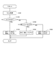
本実施形態の充電制御処理を図4のフローチャートに基づいて説明する。この処理は、充電器100が接続されているときに制御部30にて実行される処理である。図4では、第1バッテリ電圧V1が第2バッテリ電圧V2以下、すなわちV1≦V2であるものとして説明する。
The charge control process according to the present embodiment will be described with reference to the flowchart in FIG. This process is a process executed by
S201では、制御部30は、バッテリ電圧V1、V2を取得する。S202では、制御部30は、並列充電が可能か否かを判断する。バッテリ11、21の電圧差が電圧判定閾値Vthより小さい場合、並列充電可能と判定する。電圧判定閾値Vthを0とみなせる程度の値とし、バッテリ電圧V1、V2が揃ってから並列充電するようにしてもよい。また、電圧判定閾値Vthは、電圧差に応じて流れる電池間電流、および、許容電流Ilim1、Ilim2に応じた値であってもよい。並列充電ができないと判断された場合(S202:NO)、すなわち電圧差ΔVが電圧判定閾値Vth以上の場合、S203へ移行する。並列充電が可能であると判断された場合(S202:YES)、すなわち電圧差ΔVが電圧判定閾値Vthより小さい場合、S204へ移行する。
In S201, the
S203では、リレー制御部32は、並列リレー93、94を開とし、第1バッテリ11を片側充電する。並列リレー93、94が開であるので、第2バッテリ21は、充電器100から切り離されており、充電されない。S204では、リレー制御部32は、並列リレー93、94を閉とし、バッテリ11、21を並列充電する。S203およびS204において、充電量制御部33は、充電電流指令値Ic*を演算し、充電器100の図示しない制御部に通信等により送信する。
In S203, the
本実施形態では、充電器100と直接的に接続されている第1バッテリ11の電圧を、充電器100と間接的に接続されている第2バッテリ21の電圧よりも低くなるようにしておく。そして、バッテリ11、21を充電する場合、第1バッテリ11を片側充電することで、第1バッテリ電圧V1を高め、並列充電が可能になった場合、並列充電に移行する。換言すると、本実施形態では、片側充電を行うのは、充電器100と直接的に接続されている第1バッテリ11とし、第2バッテリ21の片側充電を原則として行わないようにしている。これにより、追加の開閉器を設けることなく、複数のバッテリ11、21を1つの充電器100にて適切に充電することができる。
In the present embodiment, the voltage of the first battery 11 directly connected to the
以上説明したように、電源システム1は、第1バッテリ11と、第2バッテリ21と、第1コンデンサ69と、第2コンデンサ79と、並列リレー93、94と、第1電圧検出部15と、第2電圧検出部25と、制御部30と、を備える。
As described above, the power supply system 1 includes the first battery 11, the
第1バッテリ11は、充電器100からの電力により充電可能である。第2バッテリ21は、充電器100からの電力により、第1バッテリ11と並列に充電可能である。第1コンデンサ69は、第1バッテリ11と並列に接続される。第2コンデンサ79は、第2バッテリ21と並列に接続される。並列リレー93、94は、充電器100、第1バッテリ11および第1コンデンサ69と、第2バッテリ21および第2コンデンサ79との断接を切り替え可能である。第1電圧検出部15は、第1バッテリ11の電圧である第1バッテリ電圧V1を検出する。第2電圧検出部25は、第2バッテリ21の電圧である第2バッテリ電圧V2を検出する。
The first battery 11 can be charged by electric power from the
制御部30は、第1バッテリ電圧V1および第2バッテリ電圧V2に基づき、第1バッテリ11および第2バッテリ21の充電量を制御する。制御部30は、充電器100による充電を行っていない場合、第1バッテリ電圧V1が第2バッテリ電圧V2以下となるように、第1バッテリ11および第2バッテリ21の充電量を制御する。また制御部30は、充電器100による充電を行う場合、第1バッテリ電圧V1と第2バッテリ電圧V2との電圧差ΔVが電圧判定閾値Vth以上である場合、並列リレー93、94を開とし、第1バッテリ11を片側充電し、電圧差ΔVが電圧判定閾値Vthより小さい場合、並列リレー93、94を閉とし、第1バッテリ11および第2バッテリ21を並列充電する。
The
本実施形態では、充電器100と直接的に接続されている第1バッテリ11の電圧が、第2バッテリ21の電圧よりも低くなるようにしておく。また、充電器100による充電時、電圧差ΔVが電圧判定閾値Vthより小さくなるまでは、並列リレー93、94を開として第1バッテリ11の片側充電を行い、電圧差ΔVが電圧判定閾値Vth以下となったら、並列充電に移行する。電圧差ΔVが大きい状態にてバッテリ11、21を並列接続したとき、電池間電流Ibがバッテリ11、21の許容電流Lim1、Ilim2を超えると、バッテリ11、21が劣化する虞がある。本実施形態では、電圧差ΔVが電圧判定閾値Vthより大きい場合、第1バッテリ11の片側充電とすることで、バッテリ11、12を並列接続したときの突入電流を回避可能である。これにより、バッテリ11、21およびコンデンサ69、79の劣化を抑制し、バッテリ11、21を適切に充電することができる。
In the present embodiment, the voltage of the first battery 11 directly connected to the
電源システム1は、第1インバータ60と、第2インバータ70と、をさらに備える。第1インバータ60は、MG80のコイル81、82、83の一端811、821、831、第1バッテリ11および第1コンデンサ69と接続される。第2インバータ70は、コイル81、82、83の他端812、822、832、第2バッテリ21および第2コンデンサ79と接続される。並列リレー93、94は、第1インバータ60の高電位側と第2インバータ70の高電位側とを接続する高電位側接続線91、および、第1インバータ60の低電位側と第2インバータ70の低電位側とを接続する低電位側接続線92に設けられる。
The power supply system 1 further includes a
本実施形態の電源システム1は、2電源2インバータの構成である。本実施形態では、電圧差ΔVが電圧判定閾値Vthより小さくなってから並列充電を行うことで、突入電流を低減しているので、インバータ60、70に設けられる平滑コンデンサであるコンデンサ69、79の損傷を防ぐことができる。
The power supply system 1 of the present embodiment has a configuration of two power supplies and two inverters. In the present embodiment, the inrush current is reduced by performing parallel charging after the voltage difference ΔV becomes smaller than the voltage determination threshold value Vth, so that the smoothing
制御部30は、第1インバータ60または第2インバータ70の一方を中性点化してMG80を駆動する片側駆動モードにおいて、第1バッテリ電圧V1が第2バッテリ電圧V2より大きい場合、力行時、第2インバータ70を中性点化し第1バッテリ11の電力によりMG80を駆動し、回生時、第1インバータ60を中性点化しMG80の駆動により生じる回生電力を第2バッテリ21に充電する。これにより、第1バッテリ電圧V1が第2バッテリ電圧V2より小さい状態を適切に実現することができる。
In the one-side drive mode in which one of the
第1バッテリ11の定格電圧は、第2バッテリ21の定格電圧より小さい。これにより、第1バッテリ電圧V1を第2バッテリ電圧V2より小さい状態を実現しやすい。
The rated voltage of the first battery 11 is lower than the rated voltage of the
本実施形態では、電源システム1が「電源システム」、第1バッテリ11が「第1蓄電部」、第2バッテリ21が「第2蓄電部」、MG80が「回転電機」、コイル81〜83が「多相巻線」、並列リレー93、94が「開閉器」に対応する。また、第1バッテリ電圧V1が「第1蓄電部電圧」、第2バッテリ電圧V2が「第2蓄電部電圧」に対応する。
In the present embodiment, the power supply system 1 is a “power supply system”, the first battery 11 is a “first power storage unit”, the
(他の実施形態)
上記実施形態では、第1蓄電部の定格電圧は、第2蓄電部の定格電圧より小さい。他の実施形態では、第1蓄電部の定格電圧は、第2蓄電部の定格電圧以上であってもよい。上記実施形態の回転電機は3相である。他の実施形態では、回転電機は4相以上としてもよい。上記実施形態では、回転電機は電動車両の主機モータとして用いられている。他の実施形態では、回転電機は、主機モータに限らず、例えばスタータ機能とオルタネータ機能とを併せ持つ、所謂ISG(Integrated Starter Generator)や、補機モータであってもよい。また、電源システムを車両以外の装置に適用してもよい。以上、本発明は、上記実施形態になんら限定されるものではなく、発明の趣旨を逸脱しない範囲において種々の形態で実施可能である。
(Other embodiments)
In the above embodiment, the rated voltage of the first power storage unit is lower than the rated voltage of the second power storage unit. In another embodiment, the rated voltage of the first power storage unit may be equal to or higher than the rated voltage of the second power storage unit. The rotating electric machine of the above embodiment has three phases. In another embodiment, the rotating electric machine may have four or more phases. In the above embodiment, the rotating electric machine is used as a main motor of an electric vehicle. In another embodiment, the rotating electric machine is not limited to the main motor, and may be a so-called ISG (Integrated Starter Generator) having both a starter function and an alternator function, or an auxiliary motor. Further, the power supply system may be applied to a device other than the vehicle. As described above, the present invention is not limited to the above embodiment, and can be implemented in various forms without departing from the spirit of the invention.
1・・・電源システム
11・・・第1バッテリ(第1蓄電部) 21・・・第2バッテリ(第2蓄電部)
15・・・第1電圧検出部 25・・・第2電圧検出部
30・・・制御部
60・・・第1インバータ 70・・・第2インバータ
69・・・第1コンデンサ 79・・・第2コンデンサ
80・・・MG(回転電機)
93、94・・・並列リレー(開閉器) 100・・・充電器
DESCRIPTION OF SYMBOLS 1 ... Power supply system 11 ... 1st battery (1st electric storage part) 21 ... 2nd battery (2nd electric storage part)
15 first
93, 94: parallel relay (switch) 100: charger
Claims (4)
前記充電器からの電力により前記第1蓄電部と並列に充電可能である第2蓄電部(21)と、
前記第1蓄電部と並列に接続される第1コンデンサ(69)と、
前記第2蓄電部と並列に接続される第2コンデンサ(79)と、
前記充電器、前記第1蓄電部および前記第1コンデンサと、前記第2蓄電部および前記第2コンデンサとの断接を切り替え可能である開閉器(93、94)と、
前記第1蓄電部の電圧である第1蓄電部電圧を検出する第1電圧検出部(15)と、
前記第2蓄電部の電圧である第2蓄電部電圧を検出する第2電圧検出部(25)と、
前記第1蓄電部電圧および前記第2蓄電部電圧に基づき、前記第1蓄電部および前記第2蓄電部の充電量を制御する制御部(30)と、
を備え、
前記制御部は、
前記充電器による充電を行っていない場合、前記第1蓄電部電圧が前記第2蓄電部電圧以下となるように前記第1蓄電部および前記第2蓄電部の充電量を制御し、
前記充電器による充電を行う場合、前記第1蓄電部電圧と前記第2蓄電部電圧との電圧差が電圧判定閾値以上である場合、前記開閉器を開とし、前記第1蓄電部を片側充電し、前記電圧差が前記電圧判定閾値より小さい場合、前記開閉器を閉とし、前記第1蓄電部および前記第2蓄電部を並列充電する電源システム。 A first power storage unit (11) that can be charged with electric power from the charger (100),
A second power storage unit (21) that can be charged in parallel with the first power storage unit by power from the charger;
A first capacitor (69) connected in parallel with the first power storage unit;
A second capacitor (79) connected in parallel with the second power storage unit;
Switches (93, 94) capable of switching connection / disconnection of the charger, the first power storage unit and the first capacitor, and the second power storage unit and the second capacitor;
A first voltage detection unit (15) that detects a first power storage unit voltage that is a voltage of the first power storage unit;
A second voltage detector (25) for detecting a second power storage unit voltage that is a voltage of the second power storage unit;
A control unit (30) that controls a charge amount of the first power storage unit and the second power storage unit based on the first power storage unit voltage and the second power storage unit voltage;
With
The control unit includes:
When the charging by the charger is not performed, the charge amount of the first power storage unit and the second power storage unit is controlled such that the first power storage unit voltage is equal to or lower than the second power storage unit voltage,
When charging by the charger, when the voltage difference between the first power storage unit voltage and the second power storage unit voltage is equal to or greater than a voltage determination threshold, the switch is opened, and the first power storage unit is unilaterally charged. When the voltage difference is smaller than the voltage determination threshold, the power supply system closes the switch and charges the first power storage unit and the second power storage unit in parallel.
前記多相巻線(81、82、83)の他端(812、822、832)、前記第2蓄電部および前記第2コンデンサと接続される第2インバータ(70)と、
を備え、
前記開閉器は、前記第1インバータの高電位側と前記第2インバータの高電位側とを接続する高電位側接続線(91)、および、前記第1インバータの低電位側と前記第2インバータの低電位側とを接続する低電位側接続線(92)に設けられる請求項1に記載の電源システム。 One end (811, 821, 831) of the multi-phase winding (81, 82, 83) of the rotating electric machine (80), a first inverter (60) connected to the first power storage unit and the first capacitor,
A second inverter (70) connected to the other end (812, 822, 832) of the multi-phase winding (81, 82, 83), the second power storage unit and the second capacitor;
With
The switch includes a high-potential-side connection line (91) connecting a high-potential side of the first inverter and a high-potential side of the second inverter, and a low-potential side of the first inverter and the second inverter. 2. The power supply system according to claim 1, wherein the power supply system is provided on a low potential side connection line (92) connecting the low potential side with the low potential side. 3.
Priority Applications (1)
| Application Number | Priority Date | Filing Date | Title |
|---|---|---|---|
| JP2018122316A JP7032249B2 (en) | 2018-06-27 | 2018-06-27 | Power system |
Applications Claiming Priority (1)
| Application Number | Priority Date | Filing Date | Title |
|---|---|---|---|
| JP2018122316A JP7032249B2 (en) | 2018-06-27 | 2018-06-27 | Power system |
Publications (2)
| Publication Number | Publication Date |
|---|---|
| JP2020005389A true JP2020005389A (en) | 2020-01-09 |
| JP7032249B2 JP7032249B2 (en) | 2022-03-08 |
Family
ID=69100809
Family Applications (1)
| Application Number | Title | Priority Date | Filing Date |
|---|---|---|---|
| JP2018122316A Active JP7032249B2 (en) | 2018-06-27 | 2018-06-27 | Power system |
Country Status (1)
| Country | Link |
|---|---|
| JP (1) | JP7032249B2 (en) |
Cited By (6)
| Publication number | Priority date | Publication date | Assignee | Title |
|---|---|---|---|---|
| JP2020088913A (en) * | 2018-11-15 | 2020-06-04 | トヨタ自動車株式会社 | Charger |
| CN112798968A (en) * | 2020-12-24 | 2021-05-14 | 重庆峘能电动车科技有限公司 | Battery parallel connection method, method for estimating SOC of battery parallel connection system and related equipment |
| WO2021165655A1 (en) * | 2020-02-21 | 2021-08-26 | Dyson Technology Limited | A system |
| CN113517754A (en) * | 2021-06-04 | 2021-10-19 | 中国电波传播研究所(中国电子科技集团公司第二十二研究所) | Automatic charging power supply device and method for isolating power frequency |
| WO2023131007A1 (en) * | 2022-01-05 | 2023-07-13 | 宁德时代新能源科技股份有限公司 | Charging method and system, and new energy vehicle |
| JP7680102B1 (en) * | 2025-01-17 | 2025-05-20 | Connexx Systems株式会社 | How to connect the batteries in a combined battery pack |
Citations (3)
| Publication number | Priority date | Publication date | Assignee | Title |
|---|---|---|---|---|
| JP2016203969A (en) * | 2015-04-22 | 2016-12-08 | 株式会社デンソー | Power supply |
| WO2018056262A1 (en) * | 2016-09-21 | 2018-03-29 | オートモーティブエナジーサプライ株式会社 | Power supply system |
| JP2018093648A (en) * | 2016-12-05 | 2018-06-14 | 株式会社デンソー | Drive system |
-
2018
- 2018-06-27 JP JP2018122316A patent/JP7032249B2/en active Active
Patent Citations (3)
| Publication number | Priority date | Publication date | Assignee | Title |
|---|---|---|---|---|
| JP2016203969A (en) * | 2015-04-22 | 2016-12-08 | 株式会社デンソー | Power supply |
| WO2018056262A1 (en) * | 2016-09-21 | 2018-03-29 | オートモーティブエナジーサプライ株式会社 | Power supply system |
| JP2018093648A (en) * | 2016-12-05 | 2018-06-14 | 株式会社デンソー | Drive system |
Cited By (8)
| Publication number | Priority date | Publication date | Assignee | Title |
|---|---|---|---|---|
| JP2020088913A (en) * | 2018-11-15 | 2020-06-04 | トヨタ自動車株式会社 | Charger |
| JP7067434B2 (en) | 2018-11-15 | 2022-05-16 | トヨタ自動車株式会社 | Charging device |
| US11411410B2 (en) | 2018-11-15 | 2022-08-09 | Toyota Jidosha Kabushiki Kaisha | Charging device |
| WO2021165655A1 (en) * | 2020-02-21 | 2021-08-26 | Dyson Technology Limited | A system |
| CN112798968A (en) * | 2020-12-24 | 2021-05-14 | 重庆峘能电动车科技有限公司 | Battery parallel connection method, method for estimating SOC of battery parallel connection system and related equipment |
| CN113517754A (en) * | 2021-06-04 | 2021-10-19 | 中国电波传播研究所(中国电子科技集团公司第二十二研究所) | Automatic charging power supply device and method for isolating power frequency |
| WO2023131007A1 (en) * | 2022-01-05 | 2023-07-13 | 宁德时代新能源科技股份有限公司 | Charging method and system, and new energy vehicle |
| JP7680102B1 (en) * | 2025-01-17 | 2025-05-20 | Connexx Systems株式会社 | How to connect the batteries in a combined battery pack |
Also Published As
| Publication number | Publication date |
|---|---|
| JP7032249B2 (en) | 2022-03-08 |
Similar Documents
| Publication | Publication Date | Title |
|---|---|---|
| CN113348616B (en) | Power conversion device | |
| JP7032249B2 (en) | Power system | |
| CN106104998B (en) | Control device for inverter | |
| JP6174498B2 (en) | Power converter | |
| JP6426426B2 (en) | Motor drive | |
| US11394210B2 (en) | Charging system | |
| US11303145B2 (en) | Charging system | |
| KR20140040108A (en) | Charging an energy store | |
| CN111095778A (en) | Inverter control device | |
| JP7244075B2 (en) | charging system | |
| JP7205428B2 (en) | power supply | |
| EP4491437A1 (en) | In-vehicle charging device | |
| CN119654785A (en) | Power conversion device | |
| JP2016131426A (en) | Power converter | |
| US20250038675A1 (en) | In-vehicle charging device | |
| CN119836725A (en) | Power conversion device, program | |
| EP4488104A1 (en) | In-vehicle charging device | |
| JP7629339B2 (en) | POWER CONVERSION DEVICE, PROGRAM, AND METHOD FOR CONTROLLING POWER CONVERSION DEVICE | |
| JP7063745B2 (en) | Power system | |
| CN204392134U (en) | A kind of novel electrical system | |
| JP7103320B2 (en) | Power supply | |
| CN119856361A (en) | Power conversion device and program | |
| JP5774525B2 (en) | Battery charger | |
| JP7711546B2 (en) | charging device | |
| JP7643285B2 (en) | Charging equipment |
Legal Events
| Date | Code | Title | Description |
|---|---|---|---|
| RD02 | Notification of acceptance of power of attorney |
Free format text: JAPANESE INTERMEDIATE CODE: A7422 Effective date: 20200826 |
|
| A521 | Request for written amendment filed |
Free format text: JAPANESE INTERMEDIATE CODE: A821 Effective date: 20200826 |
|
| A621 | Written request for application examination |
Free format text: JAPANESE INTERMEDIATE CODE: A621 Effective date: 20210415 |
|
| TRDD | Decision of grant or rejection written | ||
| A01 | Written decision to grant a patent or to grant a registration (utility model) |
Free format text: JAPANESE INTERMEDIATE CODE: A01 Effective date: 20220201 |
|
| A61 | First payment of annual fees (during grant procedure) |
Free format text: JAPANESE INTERMEDIATE CODE: A61 Effective date: 20220224 |
|
| R150 | Certificate of patent or registration of utility model |
Ref document number: 7032249 Country of ref document: JP Free format text: JAPANESE INTERMEDIATE CODE: R150 |
|
| R250 | Receipt of annual fees |
Free format text: JAPANESE INTERMEDIATE CODE: R250 |
|
| R250 | Receipt of annual fees |
Free format text: JAPANESE INTERMEDIATE CODE: R250 |