JP2020006466A - Pallet replacement jig and method for attaching/detaching pallet replacement jig - Google Patents
Pallet replacement jig and method for attaching/detaching pallet replacement jig Download PDFInfo
- Publication number
- JP2020006466A JP2020006466A JP2018128780A JP2018128780A JP2020006466A JP 2020006466 A JP2020006466 A JP 2020006466A JP 2018128780 A JP2018128780 A JP 2018128780A JP 2018128780 A JP2018128780 A JP 2018128780A JP 2020006466 A JP2020006466 A JP 2020006466A
- Authority
- JP
- Japan
- Prior art keywords
- pallet
- slider
- base
- engagement
- hole
- Prior art date
- Legal status (The legal status is an assumption and is not a legal conclusion. Google has not performed a legal analysis and makes no representation as to the accuracy of the status listed.)
- Granted
Links
Images


Landscapes
- Jigs For Machine Tools (AREA)
- Feeding Of Workpieces (AREA)
Abstract
【課題】 マシニングセンタやフライス盤などの工作機械との位置合わせ作業を極力少なくして、加工治具の交換作業を簡単に行うことのできるパレット交換治具を提供することである。【解決手段】 パレットベース2と、パレットベース2上をスライドするスライダ3と、スライダ3を介してパレットベース2に着脱可能に取付けられるパレット4と、を備える。また、前記パレットベース2には、パレット4の位置決め部6が設けられ、前記パレット4とスライダ3との間には、パレットベース2に位置決めされたパレット4とスライダ3とが固定される係合手段が設けられる。【選択図】 図1An object of the present invention is to provide a pallet replacement jig which can be easily replaced with a machining jig by minimizing alignment work with a machine tool such as a machining center or a milling machine. A pallet base 2, a slider 3 sliding on the pallet base 2, and a pallet 4 detachably attached to the pallet base 2 via the slider 3 are provided. Further, the pallet base 2 is provided with a positioning portion 6 for the pallet 4, and between the pallet 4 and the slider 3, the pallet 4 positioned on the pallet base 2 and the slider 3 are fixedly engaged. Means are provided. [Selection diagram] Fig. 1
Description
本発明は、マシンニングセンタやフライス盤などの工作機械にセットされるパレット交換治具及びパレット交換治具の着脱方法に関する。 The present invention relates to a pallet exchange jig set on a machine tool such as a machining center or a milling machine, and a method of attaching and detaching a pallet exchange jig.
マシンニングセンタやフライス盤などの工作機械では、テーブル上にワークを固定するための加工治具がセットされる。この加工治具はワークの種類ごとにセットされるため、その都度テーブル上において加工治具の位置決め作業が必要となり、多品種小ロットの製品を加工する場合には作業効率が悪いものとなっていた。そこで従来にあっては、加工治具を使用頻度の高いものと使用頻度の低いものとに分け、使用頻度の高い加工治具はパレットにワークを固定するための支持ブロックと位置決めブロックとを予め組み付けて標準化し、組み付けた状態のものを保管庫に準備することで、保管種類の数を少なくすると共に保管スペース・保管に係わる工数を削減していた(特許文献1参照)。 In a machine tool such as a machining center or a milling machine, a processing jig for fixing a work on a table is set. Since this processing jig is set for each type of work, it is necessary to position the processing jig on the table each time, and the work efficiency is poor when processing a wide variety of small lot products. Was. Therefore, conventionally, processing jigs are divided into those that are used frequently and those that are used less frequently, and the processing jigs that are used frequently have a support block and a positioning block that fix the work on the pallet in advance. By assembling and standardizing and preparing the assembled state in a storage, the number of storage types is reduced, and the storage space and man-hours related to storage are reduced (see Patent Document 1).
しかしながら、上記従来の加工治具にあっては、使用頻度の高い治具として保管庫に準備されている加工治具であっても、マシニングセンタにセットする際にはその都度マシニングセンタのテーブル上で位置合わせ作業が必要となり、必ずしも作業効率の向上には結びついていなかった。 However, in the above-mentioned conventional processing jig, even if a processing jig prepared in a storage as a frequently used jig is set on the table of the machining center each time it is set on the machining center. Coordination work was required, which did not necessarily lead to improvement in work efficiency.
そこで本発明の目的は、マシニングセンタやフライス盤などの工作機械との位置合わせ作業を極力少なくして、加工治具の交換作業を簡単に行うことのできるパレット交換治具及びパレット交換治具の着脱方法を提供することである。 SUMMARY OF THE INVENTION An object of the present invention is to provide a pallet exchange jig and a method of attaching and detaching a pallet exchange jig which can easily perform an operation of exchanging a processing jig by minimizing an alignment operation with a machine tool such as a machining center or a milling machine. It is to provide.
上記の課題を解決するために、本発明に係るパレット交換治具は、パレットベースと、パレットベース上をスライドするスライダと、スライダを介してパレットベースに着脱可能に取付けられるパレットと、を備え、前記パレットベースには、パレットの位置決め部が設けられ、前記パレットとスライダとの間には、パレットベースに位置決めされたパレットとスライダとが固定される係合手段が設けられる。 In order to solve the above problem, a pallet exchange jig according to the present invention includes a pallet base, a slider that slides on the pallet base, and a pallet that is detachably attached to the pallet base via the slider. The pallet base is provided with a pallet positioning portion, and between the pallet and the slider, there is provided engaging means for fixing the pallet and the slider positioned on the pallet base.
また、本発明に係るパレット交換治具の着脱方法は、パレットベース上でスライドするスライダを介してパレットベースにパレットを着脱可能に取付けるパレット交換治具の着脱方法であって、前記スライダをパレットベース上で一方向へスライドさせたときにスライダとパレットとが係合してパレットがパレットベースに固定される一方、スライダをパレットベース上で他方向へスライドさせたときに前記係合が解除されてパレットがパレットベースから離脱可能となる。 Also, a method for attaching and detaching a pallet exchange jig according to the present invention is a method for attaching and detaching a pallet exchange jig for detachably attaching a pallet to a pallet base via a slider that slides on the pallet base. When the slider is slid in one direction, the slider and the pallet are engaged and the pallet is fixed to the pallet base, while when the slider is slid in the other direction on the pallet base, the engagement is released. The pallet can be detached from the pallet base.
本発明に係るパレット交換治具によれば、パレットとパレットベースとの間にスライダを配置すると共にパレットベースに位置決めされたパレットをスライダに固定する係合手段を両者の間に設けたので、スライダを介してパレットベースにパレットを着脱可能に取付けることができる。 According to the pallet changing jig according to the present invention, the slider is arranged between the pallet and the pallet base, and the engaging means for fixing the pallet positioned on the pallet base to the slider is provided between the pallet and the pallet base. The pallet can be detachably attached to the pallet base via the pallet.
また、本発明に係るパレット交換治具の着脱方法によれば、パレットとパレットベースとの間に配置されたスライダのスライドによってスライダとパレットとの係合及び係合解除を行なうようにしたので、パレットのパレットベースに対する取付け及び離脱が極めて簡易なものとなり、パレット交換作業の効率化を図ることができる。 Further, according to the method of attaching and detaching the pallet exchange jig according to the present invention, the slider and the pallet are engaged and disengaged by sliding the slider disposed between the pallet and the pallet base. The attachment and detachment of the pallet to and from the pallet base are extremely simple, and the efficiency of the pallet replacement operation can be increased.
以下、本発明に係るパレット交換治具及びパレット交換治具の着脱方法の実施形態を図面に基づいて詳細に説明する。なお、図面は、本発明のパレット交換治具及びパレット交換治具の着脱方法を模式的に表したものである。これらの実物の寸法及び寸法比は、図面上の寸法及び寸法比と必ずしも一致していない。また、重複説明は適宜省略させることがあり、同一部材には同一符号を付与することがある。また、本発明の技術的範囲は以下で説明する各実施の形態には限定されず、特許請求の範囲に記載された発明とその均等物に及ぶ点に留意されたい。 Hereinafter, an embodiment of a pallet exchange jig and a method of attaching and detaching a pallet exchange jig according to the present invention will be described in detail with reference to the drawings. The drawings schematically show a pallet exchange jig and a method of attaching and detaching the pallet exchange jig of the present invention. The dimensions and dimensional ratios of these actual products do not always match the dimensions and dimensional ratios in the drawings. In addition, overlapping description may be omitted as appropriate, and the same members may be given the same reference numerals. Also, it should be noted that the technical scope of the present invention is not limited to the embodiments described below, but extends to the inventions described in the claims and their equivalents.
図1乃至図5には、本発明の第1実施形態に係るパレット交換治具1の構成が示される。このパレット交換治具1は、マシニングセンタのテーブルT上に固定されるパレットベース2と、パレットベース2に配置されるスライダ3と、スライダ3を介してパレットベース2に着脱可能に取付けられるパレット4と、を備える。
1 to 5 show the configuration of a pallet changing jig 1 according to a first embodiment of the present invention. The pallet changing jig 1 includes a
前記パレットベース2は矩形状の平板からなり、その上面2aにはスライダ3を所定方向にスライドさせるためのスライドガイド5が設けられる。このスライドガイド5は、パレットベース2の上面中央部に凹設される底の浅い直線状の凹溝部からなる。この凹溝部は、パレットベース2の長手方向の一端から他端まで同一断面形状で延びている。
The
上記パレットベース2の上面2aには、パレット4の取付け位置を規定する位置決め部6が設けられている。この位置決め部6は、前記スライドガイド5に沿ってその両側に複数配置される。この実施形態ではスライドガイド5の両側に3個ずつ等間隔に配置されている。位置決め部6は、それぞれが円板状のベース部6aと、ベース部6aのほぼ中心から突出する円柱状の突起部6bと、を備えている。また、ベース部6aの上面にはベース部6aの中心を通る溝部6cが凹設されている。この溝部6cは、前記スライドガイド5と平行に設けられており、ベース部6aの上面に付着したゴミや油などを逃がすことができる。位置決め部6のベース部6aは、図2に示されるように、外周の一部がスライドガイド5の上方に張り出している。このベース部6aの張出しの作用は後述する。
On an
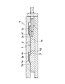
前記複数の位置決め部6にはエア抜き孔6dが設けられている。このエア抜き孔6dは、図2に示されるように、突起部6bの上端とベース部6aの側面とを連通する貫通孔であり、パレット4を位置決め部6に位置決めする際に、パレット4の位置決め孔4h内に残留する空気を抜くためのものである。エア抜き孔6dの孔径は特に限定されない。また、この実施形態では、パレット4を位置決めした際に、パレット4が適正に位置決めされていることを検知するエア漏れ検知手段が設けられている。このエア漏れ検知手段は、前記エア抜き孔6dの途中とベース部6aの上面とを連通する一対のエア漏れ孔6eを有している。また、図2に示されるように、ベース部6aの側面で開口するエア抜き孔6dに接続されるエアホース20と、エアホース20の途中に配置されたエア圧検知メータ22及びエア切替弁23を介してエアホース20の先端に接続されるコンプレッサ21と、を備えている。
The plurality of positioning
エア切替弁23を閉じた状態でコンプレッサ21から低圧エアを供給し、エア漏れ孔6eからのエア漏れの有無を検知することで、位置決め部6のベース部6aの上面とパレット4の下面4bとの密着度を判断する。例えば、エア漏れ孔6eから一定以上のエア漏れがあった場合には、パレット4の密着が不完全であるとして、アラーム音で知らせることができる。このような場合には、パレット4の上面4aの高さ位置が変位して加工精度を一定に保てないおそれがあるので、パレット4の位置決めをやり直すことが望ましい。なお、エア圧検知メータ22によって、コンプレッサ21から供給されるエア圧が一定に保たれているかどうか目視で確認することができる。パレットベース2の外周部には、マシニングセンタのテーブルTに設けられるTスロットT1にパレットベース2を固定するための固定孔2bが複数設けられている。
By supplying low-pressure air from the
前記スライダ3は、前記スライドガイド5にスライド可能に嵌り込む長尺部材からなる。スライダ3の長手方向の両側には、スライドガイド5の溝幅に対応する水平フランジ3aが張出し形成されている。また、水平フランジ3aの高さ寸法は前記スライドガイド5の溝深さにほぼ対応している。そのため、スライドガイド5の上方に張り出しているベース部6aの外周の一部がスライダ3の水平フランジ3aの上方を塞ぐことになって、スライダ3がスライドガイド5から飛び出すのを防止している。
The
図1に示されるように、前記スライダ3は、上面3’に一対の凸部を有している。この凸部は、スライダ3の長手方向に間隔をおいて形成される第1凸部3bと第2凸部3cとからなる。また、図3乃至図5に示されるように、第1凸部3bの前端には第1上向き斜面3dが、第2凸部3cの前端には第2上向き斜面3eがそれぞれ形成され、さらに第1凸部の3bの後端部にはスライダ3の上面3’との間にアリ溝部3fが形成されている。このアリ溝部3fは、第1凸部の3bの後端部とスライダ3の上面3’との間に形成される鋭角のV字溝である。
As shown in FIG. 1, the
一方、前記パレット4は、図1に示されるように、前記パレットベース2とほぼ同じ矩形状の平板からなる。パレット4の上面4aには、市販のスクロールチャックや市販のバイスなどの加工治具を装着するための取付穴4jが複数設けられる。また、パレット4の下面4bの中央部には、前記スライダ3の凸部に対応する一対の凹部が形成される。この凹部は、前記スライダ3の第1凸部3bに対応する第1凹部4cと、第2凸部3cに対応する第2凹部4dとからなる。また、図3乃至図5に示されるように、第1凹部4cの前端にはスライダ3の第1上向き斜面3dと平行な第1下向き斜面4eが形成され、第2凹部4dの前端には前記スライダ3の第2上向き斜面3eと平行な第2下向き斜面4fが形成されている。また、前記第1凹部4cの後端部にはパレット4の下面4bとの間に前記スライダ3のアリ溝部3fに嵌り込む係合突起4gが形成されている。この係合突起4gの形状は、前記アリ溝部3fのV字溝にほぼ対応したV字突起となっている。
On the other hand, as shown in FIG. 1, the
本発明では、前記スライダ3のアリ溝部3fとパレット4の係合突起4gとで係合手段を構成している。この係合手段では、スライダ3をパレットベース2上で一方向へスライドさせたときに、アリ溝部3fに係合突起4gが嵌り込むことで両者が係合し、スライダ3にパレット4が固定され、パレット4がスライダ3を介してパレットベース2に位置決めされると同時にパレット4の浮き上がりが防止される。一方、スライダ3をパレットベース2上で他方向へスライドさせたときには、アリ溝部3fから係合突起4gが抜け出ることで両者の係合が解除され、パレット4がパレットベース2から離脱可能となる。
In the present invention, the
また、本発明では、前記スライダ3に形成された第1上向き斜面3d,第2上向き斜面3eと、パレット4に形成された第1下向き斜面4e,第2下向き斜面4fとで昇降手段を構成している。この昇降手段では、スライダ3をパレットベース2上で一方向へスライドさせたときに、パレット4の第1下向き斜面4e及び第2下向き斜面4fに沿ってスライダ3の第1上向き斜面3d及び第2上向き斜面3eが上方向にスライドすることでパレットが下降し、パレットベース2に近づく。一方、スライダ3をパレットベース2上で他方向へスライドさせたときには、パレット4の第1下向き斜面4e及び第2下向き斜面4fに沿ってスライダ3の第1上向き斜面3d及び第2上向き斜面3eが下方向にスライドすることでパレット4が上昇し、パレットベース2から離れる。
In the present invention, the first
前述したスライダ3の凸部とパレット4の凹部の位置関係についてさらに説明する。図5に示されるように、スライダ3のアリ溝部3fにパレット4の係合突起4gが嵌合した時に、スライダ3の第1凸部3b及び第2凸部3cの各上向き斜面3d,3eと、パレット4の第1凹部4c及び第2凹部4dの各下向き斜面4e,4fとの間には隙間C1,C2がそれぞれ形成される。この隙間C1,C2は、アリ溝部3fの深さ寸法D1より大きく設けてある。そうすることで、図4に示したように、パレット4の各下向き斜面4e,4fに沿ってスライダ3の各上向き斜面3d,3eがスライド可能となる時点では、アリ溝部3fから係合突起4gが確実に抜け出て両者の係合が解除され、パレット4の上昇を可能とする。パレット4の上昇は、図4及び図5に示されるように、前記スライダ3の各上向き斜面3d,3eがパレット4の各下向き斜面4e,4fに沿って上方向にスライドすることで可能となる。
The positional relationship between the convex portion of the
また、図1に示したように、パレット4の下面4bには前記凹凸部の両側に3個ずつの位置決め孔4hが設けられている。この位置決め孔4hは、パレットベース2に設けられた6個の位置決め部6に対応しており、パレット4をパレットベース2に位置決めする際に用いられる。6個の位置決め孔4hのうち、対角上に位置する一対の位置決め孔4hにブッシュ4iが装着されており、パレット4の位置決めの際には、6個の位置決め孔4hのうちブッシュ4iが装着された対角上の一対の位置決め孔4hによって、パレットベース2に位置決めされる。
Further, as shown in FIG. 1, three
前記スライダ3の所定方向へのスライドは、スライダ送り機構によって実行される。スライダ送り機構としては、例えば図1及び図3に示したように、パレットベース2の一端に配置された送りねじ機構7によって行われる。この送りねじ機構7は、スライダ3を一方向又は他方向にスライドさせるものであり、パレットベース2の一端に固定された軸受8と、この軸受8に支持された送りねじ9とを備えている。軸受8は、前記送りねじ9を回転可能に支持する支持孔8aを中心部に有すると共に、スライダ3と対面する側にパレット4の一端4kが当接可能なストッパ8bを有している。この実施形態において、ストッパ8bは軸受8の平滑な前面からなる。
The
前記軸受8に支持された送りねじ9は、スライダ3の後面3gに形成された雌ネジ部3hに螺合する雄ネジ部9aを外周面に有すると共に後端部にハンドル9bを備えている。このハンドル9bを右方向又は左方向に回すことで送りねじ9が回転して、スライダ3をパレットベース2上で所定方向にスライドさせることができる。
The
図6にはスライダ送り機構の他の例が示されている。このスライダ送り機構は、油圧シリンダやエアシリンダのようなアクチュエータ24を用いるものである。アクチュエータ24のピストンに固定された棒材25の先端をスライダ3の後端部に連結し、この棒材25の押出し運動と引込み運動の機械的仕事を自動で行なうものである。
FIG. 6 shows another example of the slider feed mechanism. This slider feed mechanism uses an
次に、上記構成からなるパレット交換治具1の着脱方法について説明する。パレット4は、スライダ3との間に設けられた係合手段を介してパレットベース2に取付けられる。図1に示したように、先ずパレット4を目見当でパレットベース2の真上に配置し、パレットベース2の位置決め部6の突起部6bにパレット4の位置決め孔4hを合わせる。パレット4の位置合わせは、ブッシュ4iが装着された対角上の一対の位置決め孔4hによって行われる。
Next, a method of attaching and detaching the pallet changing jig 1 having the above configuration will be described. The
パレット4の位置合わせが完了した後、送りねじ機構7のハンドル9bを一方向に回してスライダ3を一方向(図3において矢印A方向)にスライドさせる。このスライドによって、図4に示したように、スライダ3の第1凸部3bの第1上向き斜面3d及び第2凸部3cの第2上向き斜面3eがパレット4の第1凹部4cの第1下向き斜面4e及び第2凹部4dの第2下向き斜面4f上を下方向にスライドして、パレット4が次第に下降する。そして、図2に示したように、パレット4の下面4bが位置決め部6のベース部6aの上面に当たるまでパレット4が下降し、さらにスライダ3が僅かに一方向にスライドすることで、図5に示したように、スライダ3のアリ溝部3fにパレット4の係合突起4gが嵌まり込んで両者がロックし、送りねじ機構7のハンドル9bの回転が停止される。これによって、パレット4はスライダ3を介してパレットベース2に位置決めされると同時にパレット4の浮き上がりも生じない。なお、スライダ3を一方向にスライドさせてアリ溝部3fにパレット4の係合突起4gを嵌合させる際、スライダ3と一緒にパレット4も後方にスライドするおそれがある。そこで、そのような時にはパレット4の一端4kを軸受8の前面であるストッパ8bに当てることで、パレット4のスライドを防ぐことができる。このように、パレット4は、パレットベース2を介してマシンング装置のテーブルTに位置決めされたことになる。この状態でパレット4の上面に装着された加工治具などを利用して様々な製品を加工することができる。
After the positioning of the
なお、パレット4がスライダ3を介してパレットベース2に取付けられた後、前述したエア漏れ検知手段を用いてパレット4が適正に位置決めされているかどうかを検知する。エア漏れ検知手段は、ブッシュ4iが装着された一対の位置決め孔4hに対応する一対の位置決め部6に配設されている。エアホース20の途中に位置するエア切替弁23を閉じて、コンプレッサ21から所定圧のエアーを位置決め部6に供給し、エア漏れ孔6eからエア漏れがないことを検知確認する。検知はアラーム音やエア圧検知メータ22などで行なう。
After the
一方、パレットベース2からパレット4を離脱させる場合には、送りねじ機構7のハンドル9bを逆方向に回してスライダ3を他方向(図5において矢印B方向)にスライドさせる。このスライドによって、図4に示したように、スライダ3のアリ溝部3fからパレット4の係合突起4gが抜け出て両者の係合が解除される。さらにハンドル9bを回してスライダ3をスライドさせることで、前述とは逆にスライダ3の第1凸部3b及び第2凸部3cの各上向き斜面3d,3eがパレット4の第1凹部4c及び第2凹部4dの各下向き斜面4e,4f上を上方向にスライドして、パレット4を次第に押し上げる。そして、図3に示したように、パレット4の下面4bがスライダ3の第1凸部3b及び第2凸部3cの各上面に上がりきったところで、送りねじ機構7のハンドル9bの回転を停止する。
On the other hand, when detaching the
このような操作でパレット4をリフトアップしてスライダ3から離間させ、パレットベース2との間に所定の隙間を設ける。そして、この隙間にクレーンのチェーンなどを回し込んでパレット4を吊り上げ、パレットベース2から完全に離脱させてパレット4を所定位置まで搬送したのち、新しいパレットと交換する。
By such an operation, the
図7乃至図10には本発明に係るパレット交換治具の第2実施形態が示される。このパレット交換治具11は、第1実施形態と同様、マシニングセンタのテーブルTに固定されるパレットベース2と、パレットベース2に配置されるスライダ13と、スライダ13を介してパレットベース2に着脱可能に取付けられる一対のパレット14と、を備える。
7 to 10 show a pallet changing jig according to a second embodiment of the present invention. As in the first embodiment, the
パレットベース2の上面2aの中央部には、第1実施形態と同様、直線状の凹溝部を備えるスライドガイド5が形成されている。スライドガイド5にはスライダ13がスライド可能に配置されるが、このスライダ13は、前記実施形態とは異なって、角形の長尺部材からなり、スライダ13の長手方向のほぼ中央部に、左右の側面13aを貫通する第1係合孔13bが設けられる。この第1係合13bは、スライダ13のスライド方向に対して傾斜する長孔によって形成され、特にスライダ13の後端側(図7においてスライダの長手方向の右側)から前端側(図7においてスライダの長手方向の左側)に向けて斜め下方に傾斜する楕円孔からなる。なお、スライダ13には、先の実施形態と同様、左右の側面13aの下端に水平フランジ13cが形成されている他、後面13dには送りねじ機構7の送りねじ9が螺合する雌ネジ部13eが設けられている。送りねじ機構7は、先の実施形態の構成と同様であり、パレットベース2の一端に固定された軸受8と、この軸受8に支持された送りねじ9とを備えている。なお、前記送りねじ機構7以外のスライダ送り機構として、前記実施形態の場合と同様、油圧シリンダやエアシリンダのようなアクチュエータを用いることもできる。
In the center of the
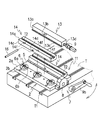
この実施形態に係るパレット14は、ナマツメバイスのべース部を構成するものであり、パレット14の上面にはナマツメやクランプユニット(いずれも図示せず)などを装着するためのTスロットT2が長手方向に設けられている。また、パレット14の側面14cには長手方向のほぼ中央部に第2係合孔14dが設けられている。この第2係合孔14dは、パレット14の左右の側面14cを水平方向に貫通する円孔からなる。本実施形態では、前記スライダ13に設けられた第1係合孔13bと、パレット14に設けられた第2係合孔14dと、両方の係合孔13b,14dに挿通される係合ピン16と、によって係合手段が構成される。また、パレット14の下面14eには3個の位置決め孔14fが設けられる。これらの位置決め孔14fは、パレットベース2のスライドガイド5に沿って設けられた3個の位置決め部6に対応して設けられており、図9及び図10に示されるように、両端の2個の位置決め孔14fに位置決め用のブッシュ14gが装着されている。本実施形態におけるパレット14は、図7に示したように、細長い直方体形状のものであり、スライダ13を挟んでその両側に一対配置されている。
The
本実施形態では、上記パレット14の上面14aにナマツメを装着した種々のナマツメバイスを複数用意しておき、そのままパレットベース2に簡単に位置決め固定することができる。そのため、マシニングセンタのテーブルTに直接ナマツメバイスを取付ける場合に比べて位置決めに要する時間が短くなり、ナマツメバイスの取付け作業を短時間で済ませることができる。
In the present embodiment, a plurality of various Japanese larch vice having the Japanese larch mounted on the
また、図11に示したように、マシニングセンタのテーブルT上にスライダ13および送りねじ機構7を備えたパレットベース2と、パレットベース2にスライダ13を介して取付けられた一対のパレット14とを備えたパレット交換治具11を複数台固定しておき、各パレット14のTスロットT2を利用することで、様々な加工治具の取付けにも対応することができ、あたかもマシニングセンタのテーブルTと同様の加工治具の取付面をパレット14上に設けることが可能となる。
As shown in FIG. 11, a
次に、上記構成からなるパレット交換治具11の着脱方法について説明する。先ず、パレット14をパレットベース2に固定する場合について説明する。図7には、パレットベース2に配置されたスライダ13の両側に一対のパレット14を固定する場合が示されている。先ず、パレットベース2の上方にパレット14を配置し、パレットベース2の位置決め部6にパレット14の位置決め孔14fを位置合わせしてから、位置決め孔14fに位置決め部6の突起部6bを挿入する。パレット14は、3個の位置決め孔14fのうち、ブッシュ14gが装着された両端の2個の位置決め孔14fによってパレットベース2に位置決めされる。
Next, a method of attaching and detaching the
次いで、図8乃至図10に示したように、一対のパレット14の各側面14cに設けられた第2係合孔14dと、一対のパレット14の間に挟まれたスライダ13の側面13aに設けられた第1係合孔13bとに係合ピン16を挿入し、一対のパレット14とスライダ13とを係合ピン16によって連結する(図8参照)。このとき、係合ピン16はスライダ13の第1係合孔13bの上端部に位置する(図9参照)。
Next, as shown in FIGS. 8 to 10, second engagement holes 14 d provided on each
次いで、送りねじ機構7のハンドル9bを一方向に回してスライダ13を一方向(図9において矢印C方向)にスライドさせる。これに伴ってスライダ13の第1係合孔13bの位置も徐々に後方へ移動する。第1係合13bは、スライダ13のスライド方向に対して傾斜する長孔として設けられ、且つ長孔の傾斜方向がスライダ13の長手方向の前方に向かって下方側に傾斜しているので、スライダ13のスライドに伴って、第1係合孔13b内を係合ピン16が下方に向けて移動する。そして、この係合ピン16の移動に伴って、図10に示したように、係合ピン16が挿入されているパレット14の第2係合孔14dが係合ピン16の移動と共に押し下げられ、結果的にパレット14自体が下降してパレットベース2側に近づくことになる。
Next, the
そして、図8及び図10に示したように、パレット14の位置決め孔14fにパレットベース2に設けられた位置決め部6の突起部6bが深く嵌り込み、パレット14の下面14eが位置決め部6のベース部6aの上面に当接した時点でハンドル9bの回転が停止される。この時、係合ピン16が一対のパレット14をパレットベース2に押し付けた状態で、パレット14の第2係合孔14dとスライダ13の第1係合孔13bとに係合される。そのため、パレット14は、スライダ13に固定され、結果的にスライダ13を介してパレットベース2に位置決めされることになる。すなわち、パレット14は、パレットベース2を介してマシンング装置のテーブルTに位置決め固定されたことになる。この状態でパレット14の上面に装着された加工治具などを利用して様々な製品を加工することができる。なお、この実施形態においても、パレット14がスライダ13を介してパレットベース2に位置決めされた後、前述したエア漏れ検知手段を用いてパレット14が適正に位置決めされているかどうかの確認が行われる。
Then, as shown in FIGS. 8 and 10, the
一方、パレット14をパレットベース2から取り外す場合には、送りねじ機構7のハンドル9bを逆方向に回してスライダ13を他方向(図10において矢印D方向)にスライドさせる。このスライドによって、スライダ13の第1係合孔13bの位置が前方に移動し、それに伴って第1係合孔13bの下部に位置していた係合ピン16が第1係合孔13b内を上方側に移動して(図9参照)、係合ピン16による係合が解除される。係合ピン16が第1係合孔13bの上端部まで移動することでハンドル9bの回転が止まる。この時点において、パレット14はパレットベース2の上面2aから離脱可能となり、パレット14を両腕で抱えて持ち上げ、又はリフターなどを用いてパレット14を吊り上げ、所定位置まで搬送することができる。
On the other hand, when removing the
図12にはロボットによるパレットの自動交換装置27の一例が示されている。この自動交換装置27は、例えば作業空間の中心部にロボット28を据え置き、その回りの三方を取り囲むように三台のマシニングセンタ29a,29b,29cを配置したものである。各マシンニングセンタ29a,29b,29cのテーブル上には、本発明に係るパレット交換治具1が設置されている。また、前記マシニングセンタが配置されていないロボット28の前側位置には段取りステーション30が設けられる。この段取りステーション30は、左右に長く延びるローラコンベア31を有し、このローラコンベア31上を複数台のパレット4が移動する。予めプログラミングされた作業手順に基づいて、ロボットアーム28aが各マシニングセンタ29a,29b,29cのテーブル上で作業していたパレット4と、段取りステーション30の中から選択された所定のパレット4との交換作業を自動的に行なうことができる。
FIG. 12 shows an example of an automatic
以上、本発明の好ましい実施例が述べられてきたが、本発明は、これら実施例に限定されず、種々の変形および変更がこれら実施例になされ得ることを認識されるべきである。 Although the preferred embodiments of the present invention have been described above, it should be recognized that the present invention is not limited to these embodiments, and that various modifications and changes can be made to these embodiments.
1,11 パレット交換治具
2 パレットベース
2a 上面
2b 固定孔
3,13 スライダ
3’ スライダの上面
3a,13c 水平フランジ
3b 第1凸部
3c 第2凸部
3d 第1上向き斜面
3e 第2上向き斜面
3f V字溝
3g,13d 後面
3h,13e 雌ネジ部
3k、13c 水平フランジ
4 パレット
4a 上面
4b 下面
4c 第1凹部
4d 第2凹部
4e 第1下向き斜面
4f 第2下向き斜面
4g V字突起
4h 位置決め孔
4i ブッシュ
4j 取付穴
4k 一端
5 スライドガイド
5a 水平溝
6 位置決め部
6a ベース部
6b 突起部
6c 溝部
6d エア抜き孔
6e エア漏れ孔
7 送りねじ機構
8 軸受
8a 支持孔
8b ストッパ
9 送りねじ
9a 雄ネジ部
9b ハンドル
13a スライダの側面
13b 第1係合孔
14 ナマツメパレット(パレット)
14a 上面
14b 凹溝
14c 側面
14d 第2係合孔
14e 下面
14f 位置決め穴
14g ブッシュ
16 係合ピン
20 エアホース
21 コンプレッサ
22 エア圧検知メータ
23 エア切換え弁
24 アクチュエータ
25 棒材
27 パレットの自動交換装置
28 ロボット
28a ロボットアーム
29a,29b,29c マシニングセンタ
30 段取りステーション
31 ローラコンベア
T テーブル
T1,T2 Tスロット
1,11
14a Upper surface 14b
Claims (12)
前記パレットベースには、パレットの位置決め部が設けられ、
前記パレットとスライダとの間には、パレットベースに位置決めされたパレットとスライダとが固定される係合手段が設けられるパレット交換治具。 A pallet base, a slider that slides on the pallet base, and a pallet detachably attached to the pallet base via the slider;
The pallet base is provided with a pallet positioning portion,
A pallet exchange jig provided between the pallet and the slider, with an engagement means for fixing the pallet and the slider positioned on the pallet base.
前記スライダのスライドによって係合ピンが第1係合孔内を移動し、第1係合孔と第2係合孔との間で係合ピンが係合される請求項1に記載のパレット交換治具。 The engagement means is inserted through a first engagement hole penetrating the side surface of the slider, a second engagement hole penetrating the side surface of the pallet, and the first engagement hole and the second engagement hole. And an engagement pin,
The pallet exchange according to claim 1, wherein the engagement pin moves in the first engagement hole by sliding of the slider, and the engagement pin is engaged between the first engagement hole and the second engagement hole. jig.
前記スライダをパレットベース上で一方向へスライドさせたときにスライダとパレットとが係合してパレットがパレットベースに固定される一方、スライダをパレットベース上で他方向へスライドさせたときに前記係合が解除されてパレットがパレットベースから離脱可能となるパレット交換治具の着脱方法。 A pallet replacement jig for attaching and detaching a pallet to a pallet base via a slider that slides on the pallet base, comprising:
When the slider is slid in one direction on the pallet base, the slider and the pallet are engaged with each other to fix the pallet to the pallet base. A pallet exchange jig that allows the pallet to be detached from the pallet base when the pallet is released.
Priority Applications (1)
| Application Number | Priority Date | Filing Date | Title |
|---|---|---|---|
| JP2018128780A JP6806378B2 (en) | 2018-07-06 | 2018-07-06 | How to attach / detach the pallet replacement jig and pallet replacement jig |
Applications Claiming Priority (1)
| Application Number | Priority Date | Filing Date | Title |
|---|---|---|---|
| JP2018128780A JP6806378B2 (en) | 2018-07-06 | 2018-07-06 | How to attach / detach the pallet replacement jig and pallet replacement jig |
Publications (2)
| Publication Number | Publication Date |
|---|---|
| JP2020006466A true JP2020006466A (en) | 2020-01-16 |
| JP6806378B2 JP6806378B2 (en) | 2021-01-06 |
Family
ID=69150092
Family Applications (1)
| Application Number | Title | Priority Date | Filing Date |
|---|---|---|---|
| JP2018128780A Expired - Fee Related JP6806378B2 (en) | 2018-07-06 | 2018-07-06 | How to attach / detach the pallet replacement jig and pallet replacement jig |
Country Status (1)
| Country | Link |
|---|---|
| JP (1) | JP6806378B2 (en) |
Cited By (7)
| Publication number | Priority date | Publication date | Assignee | Title |
|---|---|---|---|---|
| CN114228134A (en) * | 2021-11-30 | 2022-03-25 | 深圳市洋明达科技有限公司 | 3D printer |
| CN114770191A (en) * | 2022-04-25 | 2022-07-22 | 博众精工科技股份有限公司 | Online disassembling jig mechanism, system and method |
| CN115709965A (en) * | 2022-11-15 | 2023-02-24 | 耐优生物技术(上海)有限公司 | Uncapping mechanism for sample tube uncapping machine and uncapping machine |
| KR20240007341A (en) * | 2022-07-08 | 2024-01-16 | 이더블유에스 코리아 주식회사 | Jig for workpiece processing |
| WO2024121922A1 (en) * | 2022-12-06 | 2024-06-13 | ヤマハ発動機株式会社 | Load supporting device, conveyance system, and load supporting method |
| KR102925893B1 (en) * | 2025-08-25 | 2026-02-11 | 배상곤 | Laser Welding and Cutting Combined Syste |
| JP7851678B2 (en) | 2022-12-06 | 2026-04-27 | ヤマハ発動機株式会社 | Load support device, conveying system, and load support method |
Citations (16)
| Publication number | Priority date | Publication date | Assignee | Title |
|---|---|---|---|---|
| JPS57108843U (en) * | 1980-12-26 | 1982-07-05 | ||
| JPS58155145A (en) * | 1982-03-09 | 1983-09-14 | Niigata Eng Co Ltd | Pallet conveyor for automatic pallet exchanger |
| JPS618247A (en) * | 1984-03-09 | 1986-01-14 | ビユヒラ−・ベ−−セツト・アクチエンゲゼルシヤフト | Device for holding article at position of three-dimensional space |
| JPH01164534A (en) * | 1987-12-10 | 1989-06-28 | Sz Srl | Working material mounting pallet |
| JPH0539840U (en) * | 1991-10-28 | 1993-05-28 | 日立精機株式会社 | Machine tools with removable pallets of different sizes |
| JPH06126582A (en) * | 1992-10-12 | 1994-05-10 | Tsudakoma Corp | Pallet changing device |
| JPH06126581A (en) * | 1992-10-12 | 1994-05-10 | Tsudakoma Corp | Fixing device for objective member |
| JPH06278857A (en) * | 1993-03-30 | 1994-10-04 | Nippon Densan Corp | Transport device |
| JPH09103921A (en) * | 1995-10-06 | 1997-04-22 | Makino Milling Mach Co Ltd | Electric discharge machine |
| JP2002137136A (en) * | 2000-10-27 | 2002-05-14 | Mori Seiki Co Ltd | Machine tool pallet changer |
| JP2003039264A (en) * | 2001-07-24 | 2003-02-12 | Pascal Corp | Work pallet positioning and fixing device |
| JP2010131718A (en) * | 2008-12-05 | 2010-06-17 | Homma Machinery Co Ltd | Pallet changer for machine tools |
| JP2011251376A (en) * | 2010-06-03 | 2011-12-15 | Pascal Engineering Corp | Object positioning-fixing device |
| JP2013082023A (en) * | 2011-10-07 | 2013-05-09 | Tmc Co Ltd | Pallet changer |
| JP5864827B1 (en) * | 2015-08-31 | 2016-02-17 | ヤマザキマザック株式会社 | Table clamp device and pallet changer equipped with the same |
| US20170021464A1 (en) * | 2013-09-06 | 2017-01-26 | Mag Ias Gmbh | Workpiece adapter apparatus, combination of workpiece holding apparatus and workpiece adapter apparatus, and machine tool |
-
2018
- 2018-07-06 JP JP2018128780A patent/JP6806378B2/en not_active Expired - Fee Related
Patent Citations (16)
| Publication number | Priority date | Publication date | Assignee | Title |
|---|---|---|---|---|
| JPS57108843U (en) * | 1980-12-26 | 1982-07-05 | ||
| JPS58155145A (en) * | 1982-03-09 | 1983-09-14 | Niigata Eng Co Ltd | Pallet conveyor for automatic pallet exchanger |
| JPS618247A (en) * | 1984-03-09 | 1986-01-14 | ビユヒラ−・ベ−−セツト・アクチエンゲゼルシヤフト | Device for holding article at position of three-dimensional space |
| JPH01164534A (en) * | 1987-12-10 | 1989-06-28 | Sz Srl | Working material mounting pallet |
| JPH0539840U (en) * | 1991-10-28 | 1993-05-28 | 日立精機株式会社 | Machine tools with removable pallets of different sizes |
| JPH06126582A (en) * | 1992-10-12 | 1994-05-10 | Tsudakoma Corp | Pallet changing device |
| JPH06126581A (en) * | 1992-10-12 | 1994-05-10 | Tsudakoma Corp | Fixing device for objective member |
| JPH06278857A (en) * | 1993-03-30 | 1994-10-04 | Nippon Densan Corp | Transport device |
| JPH09103921A (en) * | 1995-10-06 | 1997-04-22 | Makino Milling Mach Co Ltd | Electric discharge machine |
| JP2002137136A (en) * | 2000-10-27 | 2002-05-14 | Mori Seiki Co Ltd | Machine tool pallet changer |
| JP2003039264A (en) * | 2001-07-24 | 2003-02-12 | Pascal Corp | Work pallet positioning and fixing device |
| JP2010131718A (en) * | 2008-12-05 | 2010-06-17 | Homma Machinery Co Ltd | Pallet changer for machine tools |
| JP2011251376A (en) * | 2010-06-03 | 2011-12-15 | Pascal Engineering Corp | Object positioning-fixing device |
| JP2013082023A (en) * | 2011-10-07 | 2013-05-09 | Tmc Co Ltd | Pallet changer |
| US20170021464A1 (en) * | 2013-09-06 | 2017-01-26 | Mag Ias Gmbh | Workpiece adapter apparatus, combination of workpiece holding apparatus and workpiece adapter apparatus, and machine tool |
| JP5864827B1 (en) * | 2015-08-31 | 2016-02-17 | ヤマザキマザック株式会社 | Table clamp device and pallet changer equipped with the same |
Cited By (11)
| Publication number | Priority date | Publication date | Assignee | Title |
|---|---|---|---|---|
| CN114228134A (en) * | 2021-11-30 | 2022-03-25 | 深圳市洋明达科技有限公司 | 3D printer |
| CN114228134B (en) * | 2021-11-30 | 2023-07-25 | 深圳市洋明达科技有限公司 | 3D printer |
| CN114770191A (en) * | 2022-04-25 | 2022-07-22 | 博众精工科技股份有限公司 | Online disassembling jig mechanism, system and method |
| CN114770191B (en) * | 2022-04-25 | 2023-08-11 | 博众精工科技股份有限公司 | Online disassembly jig mechanism, system and method |
| KR20240007341A (en) * | 2022-07-08 | 2024-01-16 | 이더블유에스 코리아 주식회사 | Jig for workpiece processing |
| KR102629140B1 (en) * | 2022-07-08 | 2024-01-25 | 이더블유에스 코리아 주식회사 | Jig for workpiece processing |
| CN115709965A (en) * | 2022-11-15 | 2023-02-24 | 耐优生物技术(上海)有限公司 | Uncapping mechanism for sample tube uncapping machine and uncapping machine |
| WO2024121922A1 (en) * | 2022-12-06 | 2024-06-13 | ヤマハ発動機株式会社 | Load supporting device, conveyance system, and load supporting method |
| JPWO2024121922A1 (en) * | 2022-12-06 | 2024-06-13 | ||
| JP7851678B2 (en) | 2022-12-06 | 2026-04-27 | ヤマハ発動機株式会社 | Load support device, conveying system, and load support method |
| KR102925893B1 (en) * | 2025-08-25 | 2026-02-11 | 배상곤 | Laser Welding and Cutting Combined Syste |
Also Published As
| Publication number | Publication date |
|---|---|
| JP6806378B2 (en) | 2021-01-06 |
Similar Documents
| Publication | Publication Date | Title |
|---|---|---|
| JP2020006466A (en) | Pallet replacement jig and method for attaching/detaching pallet replacement jig | |
| US4253559A (en) | Pallet locating and clamping mechanism for a transfer machine | |
| CN202479429U (en) | Full-automatic nailing machine | |
| CN206277176U (en) | The clamping tooling of annular disk-like accessory | |
| JP2006000855A (en) | Bending apparatus, its method and bending die | |
| CN106862968A (en) | The clamping tooling of annular disk-like accessory | |
| TW201637750A (en) | Forging machine with robotic handler | |
| US20170120404A1 (en) | Workpiece auto-centering apparatus and auto-centering method | |
| JP2017136657A (en) | Pressing-in method and pressing-in system | |
| CN113814728A (en) | A kind of automatic assembly welding workpiece equipment | |
| JP5869457B2 (en) | Work pallet and fixture used therefor | |
| CN213531735U (en) | Special-shaped piece quick-change precision adjusting device based on zero positioner | |
| JPH09168928A (en) | Work piece positioning device | |
| KR102616675B1 (en) | Jig for metal working | |
| CN105689877B (en) | Spot welding manipulator for gas burner | |
| US4582306A (en) | Vise jaw | |
| JP3677931B2 (en) | Parts processing equipment with transport mechanism | |
| EP1258320A2 (en) | Drilling and milling machine for applying metal elements to furniture pieces | |
| CN213168985U (en) | Positioning tray for quickly replacing automobile brake caliper body machining clamp | |
| CN212683267U (en) | Zero point positioning mechanism of processing machine | |
| KR101898267B1 (en) | jig assembly for processing an hexahedron type blocks | |
| CN219358778U (en) | Positioning fixture suitable for CNC automatic feeding and discharging | |
| CN106113160A (en) | One has Three-dimension process function fixture structure | |
| CN113333803A (en) | One-side two-pin positioning tool for large workpiece | |
| CN107378584A (en) | A kind of numerical control machining center tool magazine |
Legal Events
| Date | Code | Title | Description |
|---|---|---|---|
| A621 | Written request for application examination |
Free format text: JAPANESE INTERMEDIATE CODE: A621 Effective date: 20200327 |
|
| A871 | Explanation of circumstances concerning accelerated examination |
Free format text: JAPANESE INTERMEDIATE CODE: A871 Effective date: 20200403 |
|
| A975 | Report on accelerated examination |
Free format text: JAPANESE INTERMEDIATE CODE: A971005 Effective date: 20200626 |
|
| A131 | Notification of reasons for refusal |
Free format text: JAPANESE INTERMEDIATE CODE: A131 Effective date: 20200630 |
|
| A521 | Request for written amendment filed |
Free format text: JAPANESE INTERMEDIATE CODE: A523 Effective date: 20200818 |
|
| TRDD | Decision of grant or rejection written | ||
| A01 | Written decision to grant a patent or to grant a registration (utility model) |
Free format text: JAPANESE INTERMEDIATE CODE: A01 Effective date: 20201117 |
|
| A61 | First payment of annual fees (during grant procedure) |
Free format text: JAPANESE INTERMEDIATE CODE: A61 Effective date: 20201127 |
|
| R150 | Certificate of patent or registration of utility model |
Ref document number: 6806378 Country of ref document: JP Free format text: JAPANESE INTERMEDIATE CODE: R150 |
|
| LAPS | Cancellation because of no payment of annual fees |