JP2021521402A - Boiler heating system - Google Patents
Boiler heating system Download PDFInfo
- Publication number
- JP2021521402A JP2021521402A JP2020552825A JP2020552825A JP2021521402A JP 2021521402 A JP2021521402 A JP 2021521402A JP 2020552825 A JP2020552825 A JP 2020552825A JP 2020552825 A JP2020552825 A JP 2020552825A JP 2021521402 A JP2021521402 A JP 2021521402A
- Authority
- JP
- Japan
- Prior art keywords
- water
- cylinder
- heating
- partition wall
- heating element
- Prior art date
- Legal status (The legal status is an assumption and is not a legal conclusion. Google has not performed a legal analysis and makes no representation as to the accuracy of the status listed.)
- Granted
Links
Images


Classifications
-
- F—MECHANICAL ENGINEERING; LIGHTING; HEATING; WEAPONS; BLASTING
- F24—HEATING; RANGES; VENTILATING
- F24H—FLUID HEATERS, e.g. WATER OR AIR HEATERS, HAVING HEAT-GENERATING MEANS, e.g. HEAT PUMPS, IN GENERAL
- F24H1/00—Water heaters, e.g. boilers, continuous-flow heaters or water-storage heaters
- F24H1/18—Water-storage heaters
- F24H1/20—Water-storage heaters with immersed heating elements, e.g. electric elements or furnace tubes
- F24H1/205—Water-storage heaters with immersed heating elements, e.g. electric elements or furnace tubes with furnace tubes
-
- F—MECHANICAL ENGINEERING; LIGHTING; HEATING; WEAPONS; BLASTING
- F24—HEATING; RANGES; VENTILATING
- F24H—FLUID HEATERS, e.g. WATER OR AIR HEATERS, HAVING HEAT-GENERATING MEANS, e.g. HEAT PUMPS, IN GENERAL
- F24H1/00—Water heaters, e.g. boilers, continuous-flow heaters or water-storage heaters
- F24H1/10—Continuous-flow heaters, i.e. heaters in which heat is generated only while the water is flowing, e.g. with direct contact of the water with the heating medium
- F24H1/12—Continuous-flow heaters, i.e. heaters in which heat is generated only while the water is flowing, e.g. with direct contact of the water with the heating medium in which the water is kept separate from the heating medium
- F24H1/121—Continuous-flow heaters, i.e. heaters in which heat is generated only while the water is flowing, e.g. with direct contact of the water with the heating medium in which the water is kept separate from the heating medium using electric energy supply
-
- F—MECHANICAL ENGINEERING; LIGHTING; HEATING; WEAPONS; BLASTING
- F24—HEATING; RANGES; VENTILATING
- F24B—DOMESTIC STOVES OR RANGES FOR SOLID FUELS; IMPLEMENTS FOR USE IN CONNECTION WITH STOVES OR RANGES
- F24B9/00—Stoves, ranges or flue-gas ducts, with additional provisions for heating water
-
- F—MECHANICAL ENGINEERING; LIGHTING; HEATING; WEAPONS; BLASTING
- F24—HEATING; RANGES; VENTILATING
- F24B—DOMESTIC STOVES OR RANGES FOR SOLID FUELS; IMPLEMENTS FOR USE IN CONNECTION WITH STOVES OR RANGES
- F24B9/00—Stoves, ranges or flue-gas ducts, with additional provisions for heating water
- F24B9/006—Stoves, ranges or flue-gas ducts, with additional provisions for heating water flue-gas ducts
-
- F—MECHANICAL ENGINEERING; LIGHTING; HEATING; WEAPONS; BLASTING
- F24—HEATING; RANGES; VENTILATING
- F24B—DOMESTIC STOVES OR RANGES FOR SOLID FUELS; IMPLEMENTS FOR USE IN CONNECTION WITH STOVES OR RANGES
- F24B9/00—Stoves, ranges or flue-gas ducts, with additional provisions for heating water
- F24B9/04—Stoves, ranges or flue-gas ducts, with additional provisions for heating water in closed containers
-
- F—MECHANICAL ENGINEERING; LIGHTING; HEATING; WEAPONS; BLASTING
- F24—HEATING; RANGES; VENTILATING
- F24H—FLUID HEATERS, e.g. WATER OR AIR HEATERS, HAVING HEAT-GENERATING MEANS, e.g. HEAT PUMPS, IN GENERAL
- F24H1/00—Water heaters, e.g. boilers, continuous-flow heaters or water-storage heaters
- F24H1/0018—Water heaters, e.g. boilers, continuous-flow heaters or water-storage heaters using electric energy supply
-
- F—MECHANICAL ENGINEERING; LIGHTING; HEATING; WEAPONS; BLASTING
- F24—HEATING; RANGES; VENTILATING
- F24H—FLUID HEATERS, e.g. WATER OR AIR HEATERS, HAVING HEAT-GENERATING MEANS, e.g. HEAT PUMPS, IN GENERAL
- F24H1/00—Water heaters, e.g. boilers, continuous-flow heaters or water-storage heaters
- F24H1/0027—Water heaters, e.g. boilers, continuous-flow heaters or water-storage heaters using fluid fuel
- F24H1/0036—Water heaters, e.g. boilers, continuous-flow heaters or water-storage heaters using fluid fuel of the sealed type
-
- F—MECHANICAL ENGINEERING; LIGHTING; HEATING; WEAPONS; BLASTING
- F24—HEATING; RANGES; VENTILATING
- F24H—FLUID HEATERS, e.g. WATER OR AIR HEATERS, HAVING HEAT-GENERATING MEANS, e.g. HEAT PUMPS, IN GENERAL
- F24H1/00—Water heaters, e.g. boilers, continuous-flow heaters or water-storage heaters
- F24H1/10—Continuous-flow heaters, i.e. heaters in which heat is generated only while the water is flowing, e.g. with direct contact of the water with the heating medium
- F24H1/12—Continuous-flow heaters, i.e. heaters in which heat is generated only while the water is flowing, e.g. with direct contact of the water with the heating medium in which the water is kept separate from the heating medium
- F24H1/124—Continuous-flow heaters, i.e. heaters in which heat is generated only while the water is flowing, e.g. with direct contact of the water with the heating medium in which the water is kept separate from the heating medium using fluid fuel
-
- F—MECHANICAL ENGINEERING; LIGHTING; HEATING; WEAPONS; BLASTING
- F24—HEATING; RANGES; VENTILATING
- F24H—FLUID HEATERS, e.g. WATER OR AIR HEATERS, HAVING HEAT-GENERATING MEANS, e.g. HEAT PUMPS, IN GENERAL
- F24H1/00—Water heaters, e.g. boilers, continuous-flow heaters or water-storage heaters
- F24H1/18—Water-storage heaters
- F24H1/181—Construction of the tank
- F24H1/182—Insulation
-
- F—MECHANICAL ENGINEERING; LIGHTING; HEATING; WEAPONS; BLASTING
- F24—HEATING; RANGES; VENTILATING
- F24H—FLUID HEATERS, e.g. WATER OR AIR HEATERS, HAVING HEAT-GENERATING MEANS, e.g. HEAT PUMPS, IN GENERAL
- F24H1/00—Water heaters, e.g. boilers, continuous-flow heaters or water-storage heaters
- F24H1/18—Water-storage heaters
- F24H1/20—Water-storage heaters with immersed heating elements, e.g. electric elements or furnace tubes
- F24H1/201—Water-storage heaters with immersed heating elements, e.g. electric elements or furnace tubes using electric energy supply
-
- F—MECHANICAL ENGINEERING; LIGHTING; HEATING; WEAPONS; BLASTING
- F24—HEATING; RANGES; VENTILATING
- F24H—FLUID HEATERS, e.g. WATER OR AIR HEATERS, HAVING HEAT-GENERATING MEANS, e.g. HEAT PUMPS, IN GENERAL
- F24H1/00—Water heaters, e.g. boilers, continuous-flow heaters or water-storage heaters
- F24H1/22—Water heaters other than continuous-flow or water-storage heaters, e.g. water heaters for central heating
- F24H1/24—Water heaters other than continuous-flow or water-storage heaters, e.g. water heaters for central heating with water mantle surrounding the combustion chamber or chambers
- F24H1/26—Water heaters other than continuous-flow or water-storage heaters, e.g. water heaters for central heating with water mantle surrounding the combustion chamber or chambers the water mantle forming an integral body
- F24H1/28—Water heaters other than continuous-flow or water-storage heaters, e.g. water heaters for central heating with water mantle surrounding the combustion chamber or chambers the water mantle forming an integral body including one or more furnace or fire tubes
- F24H1/285—Water heaters other than continuous-flow or water-storage heaters, e.g. water heaters for central heating with water mantle surrounding the combustion chamber or chambers the water mantle forming an integral body including one or more furnace or fire tubes with the fire tubes arranged alongside the combustion chamber
-
- F—MECHANICAL ENGINEERING; LIGHTING; HEATING; WEAPONS; BLASTING
- F24—HEATING; RANGES; VENTILATING
- F24H—FLUID HEATERS, e.g. WATER OR AIR HEATERS, HAVING HEAT-GENERATING MEANS, e.g. HEAT PUMPS, IN GENERAL
- F24H9/00—Details
- F24H9/0005—Details for water heaters
- F24H9/001—Guiding means
-
- F—MECHANICAL ENGINEERING; LIGHTING; HEATING; WEAPONS; BLASTING
- F24—HEATING; RANGES; VENTILATING
- F24H—FLUID HEATERS, e.g. WATER OR AIR HEATERS, HAVING HEAT-GENERATING MEANS, e.g. HEAT PUMPS, IN GENERAL
- F24H9/00—Details
- F24H9/0005—Details for water heaters
- F24H9/001—Guiding means
- F24H9/0015—Guiding means in water channels
- F24H9/0021—Sleeves surrounding heating elements or heating pipes, e.g. pipes filled with heat transfer fluid, for guiding heated liquid
-
- F—MECHANICAL ENGINEERING; LIGHTING; HEATING; WEAPONS; BLASTING
- F24—HEATING; RANGES; VENTILATING
- F24H—FLUID HEATERS, e.g. WATER OR AIR HEATERS, HAVING HEAT-GENERATING MEANS, e.g. HEAT PUMPS, IN GENERAL
- F24H9/00—Details
- F24H9/18—Arrangement or mounting of grates or heating means
- F24H9/1809—Arrangement or mounting of grates or heating means for water heaters
- F24H9/1818—Arrangement or mounting of electric heating means
-
- F—MECHANICAL ENGINEERING; LIGHTING; HEATING; WEAPONS; BLASTING
- F24—HEATING; RANGES; VENTILATING
- F24H—FLUID HEATERS, e.g. WATER OR AIR HEATERS, HAVING HEAT-GENERATING MEANS, e.g. HEAT PUMPS, IN GENERAL
- F24H9/00—Details
- F24H9/18—Arrangement or mounting of grates or heating means
- F24H9/1809—Arrangement or mounting of grates or heating means for water heaters
- F24H9/1832—Arrangement or mounting of combustion heating means, e.g. grates or burners
- F24H9/1836—Arrangement or mounting of combustion heating means, e.g. grates or burners using fluid fuel
Landscapes
- Engineering & Computer Science (AREA)
- Chemical & Material Sciences (AREA)
- Combustion & Propulsion (AREA)
- Mechanical Engineering (AREA)
- General Engineering & Computer Science (AREA)
- Physics & Mathematics (AREA)
- Thermal Sciences (AREA)
- Heat-Pump Type And Storage Water Heaters (AREA)
- External Artificial Organs (AREA)
Abstract
一態様では、本発明は、その中に加熱されるべき水を貯蔵するための中空壁シリンダと、中空壁シリンダ内部でその垂直壁から離れて配設されたシリンダ形状の隔壁であって、隔壁の内側と隔壁の外側との間で水の移行を可能にするための上部水路及び下部水路を有する、隔壁と、中空壁シリンダの内部空間内に配設された加熱素子と、中空壁シリンダの下側に配設された吸水口と、中空壁シリンダの上側に配設された排水口と、を備え、それにより、(a)加熱素子と水とを直接接触させることなく水を加熱することを可能にし、その結果、湯垢の堆積を全く生じさせず、(b)上昇する水と下降する水とを分離して、それにより水の加温を加速する、ボイラー加熱システムを対象とする。In one aspect, the present invention is a hollow wall cylinder for storing water to be heated in the hollow wall cylinder and a cylinder-shaped partition wall disposed inside the hollow wall cylinder away from the vertical wall. A partition wall, a heating element disposed within the internal space of the hollow wall cylinder, and a hollow wall cylinder having an upper and lower channel to allow water transfer between the inside of the partition and the outside of the partition. It is provided with a water inlet arranged on the lower side and a drainage port arranged on the upper side of the hollow wall cylinder, whereby (a) heating water without direct contact between the heating element and water. As a result, it is intended for boiler heating systems that do not cause any buildup of water stains and (b) separate the rising and falling water, thereby accelerating the heating of the water.
Description
本発明は、ボイラー加熱技術の分野に関する。 The present invention relates to the field of boiler heating technology.
現在、ボイラー加熱システムは、主に電気加熱及びガス加熱に基づいている。これらのシステムは、多くの欠点を有することを特徴とする。例えば、欠点のうちの1つは加熱速度であり、このため、水の加温速度を向上させるための多くの試みがなされてきた。 Currently, boiler heating systems are mainly based on electric heating and gas heating. These systems are characterized by having many drawbacks. For example, one of the drawbacks is the heating rate, which has led to many attempts to improve the heating rate of water.
加えて、電気加熱素子を用いた数回の加熱セッションの後で、加熱素子上に湯垢が堆積される。湯垢は加熱されるべき水から加熱素子を隔離するため、加温速度が低下するだけでなく、より多くのエネルギーが消費される。 In addition, after several heating sessions with the electric heating element, scale is deposited on the heating element. Since scale isolates the heating element from the water to be heated, it not only slows down the heating rate, but also consumes more energy.
要約すると、現行の水加熱技術は、遅い加熱速度、エネルギーの浪費、減価償却、及びメンテナンスを特徴とする。 In summary, current water heating techniques are characterized by slow heating rates, wasted energy, depreciation, and maintenance.
本発明のその他の目的及び利点は、説明が進むと共に明らかになるであろう。 Other objects and advantages of the present invention will become apparent as the description progresses.
一態様では、本発明は、その中に加熱されるべき水を貯蔵するための中空壁シリンダ(12)と、中空壁シリンダ(12)内部でその垂直壁から離れて配設されたシリンダ形状の隔壁(13)であって、隔壁の内側(チャンバH)と隔壁の外側(チャンバA)との間で水の移行を可能にするための上部水路(18)及び下部水路(19)を有する、隔壁(13)と、中空壁シリンダの内部空間(チャンバC)内に配設された加熱素子(15)と、中空壁シリンダ(12)の下側に配設された吸水口(10)と、中空壁シリンダ(12)の上側に配設された排水口(11)と、を備え、それにより、(a)加熱素子と水とを直接接触させることなく水を加熱することを可能にし、その結果、湯垢の堆積を全く生じさせず、(b)上昇する水と下降する水とを分離して、それにより水の加温を加速する、ボイラー加熱システム(100)を対象とする。 In one aspect, the present invention comprises a hollow wall cylinder (12) for storing water to be heated therein and a cylinder shape disposed inside the hollow wall cylinder (12) away from its vertical wall. The partition (13) has an upper channel (18) and a lower channel (19) to allow water transfer between the inside of the partition (chamber H) and the outside of the partition (chamber A). A partition wall (13), a heating element (15) arranged in the internal space (chamber C) of the hollow wall cylinder, and a water suction port (10) arranged under the hollow wall cylinder (12). It is provided with a drain port (11) disposed above the hollow wall cylinder (12), which allows (a) to heat the water without direct contact between the heating element and the water. As a result, the boiler heating system (100) is targeted, which does not cause any accumulation of water stains and (b) separates the rising water from the falling water, thereby accelerating the heating of the water.
システムは、システムの加熱速度を調節するために、その中に加熱素子(15)が配設される内部空間(チャンバC)の蓋(17)を更に備え得る。 The system may further include a lid (17) of an internal space (chamber C) in which a heating element (15) is disposed in order to adjust the heating rate of the system.
システムは、入れ子形態の隔壁などの、隔壁内の空間を調節してそれにより水の加熱速度を調節するための手段(図示せず)を更に備え得る。 The system may further include means (not shown) for adjusting the space within the partition, such as a nested partition, thereby adjusting the heating rate of water.
加熱素子は、電気的のみならず、火炎などの燃焼に基づくものであってもよい。 The heating element may be based not only on electricity but also on combustion such as flame.
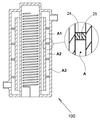
本発明の一実施形態によれば、チャンバAの空間は、それぞれ孔(25)を有する隔壁(24)によって分割され、それにより加熱された水の冷却速度を抑える。 According to one embodiment of the present invention, the space of the chamber A is divided by partition walls (24), each having a hole (25), thereby suppressing the cooling rate of the heated water.
本発明の一実施形態によれば、加熱素子(15)は渦巻き線形態である。 According to one embodiment of the present invention, the heating element (15) is in the form of a spiral wire.
参照番号は、本発明の理解を容易にするため、本明細書で説明及び図示される実施形態中の要素を指摘するために用いられている。これらは単に例示的なものであり、限定するものではない。また、本発明の前述の実施形態が、そのシステム及び方法と共に説明及び図示されているが、これらは単に例示的なものであり、限定するものではない。 Reference numbers are used to point out elements in embodiments described and illustrated herein to facilitate understanding of the invention. These are merely exemplary and are not limiting. Also, although the aforementioned embodiments of the present invention have been described and illustrated along with their systems and methods, they are merely exemplary and not limited.
本発明の好ましい実施形態、機構、態様、及び利点を、以下の図面と併せて本明細書で説明する。
図面は必ずしも縮尺通りに描かれているわけではないことを理解されたい。 It should be understood that the drawings are not always drawn to scale.
本発明は、説明的であることが意図され、限定的ではない、以下の好ましい実施形態の詳細な説明(「最良の形態」)から理解されよう。簡潔さのために、いくつかの周知される機構、方法、システム、手順、構成要素、回路などは詳細に説明しない。 The present invention will be understood from the following detailed description of preferred embodiments (“best embodiments”) intended to be descriptive and not limiting. For brevity, some well-known mechanisms, methods, systems, procedures, components, circuits, etc. are not described in detail.
システムの構造
システム100の槽は、水を貯蔵する、中空壁を有する垂直シリンダの形態である。
したがって、従来技術のボイラーは容器形態の槽を有するが、本発明による水槽は、中空壁を有する垂直シリンダであり、その中に水が配設される。したがって、槽の中心は中空のシリンダである。
Structure of the system The tank of the
Therefore, the boiler of the prior art has a tank in the form of a container, but the water tank according to the present invention is a vertical cylinder having a hollow wall, and water is arranged therein. Therefore, the center of the tank is a hollow cylinder.
中空のシリンダの中心内の空間内部に加熱素子が配置される。したがって、加熱素子は渦巻き線など電気的であってもよく、又は更には火であってもよい。 A heating element is arranged inside the space inside the center of the hollow cylinder. Therefore, the heating element may be electrical, such as a spiral, or even fire.
シリンダの中空壁の空間は、垂直シリンダ形態の隔壁によって分割される。それでもなお、隔壁シリンダは、本明細書の下記で詳述するように、循環を可能にするために、その上側及びその下側からの水の通過を可能にする。 The space in the hollow wall of the cylinder is divided by a bulkhead in the form of a vertical cylinder. Nonetheless, the bulkhead cylinder allows the passage of water from above and below it to allow circulation, as detailed below in this specification.
図1は、本発明の一実施形態による、ボイラー加熱システム100を図示する。
FIG. 1 illustrates a
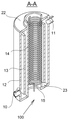
図2は、ボイラー加熱システムの断面図である。 FIG. 2 is a cross-sectional view of the boiler heating system.
図3は、断面A−Aがその中で画定される、ボイラー加熱システムの正面図である。 FIG. 3 is a front view of a boiler heating system in which cross sections AA are defined.
図4は、断面A−Aの斜視図である。 FIG. 4 is a perspective view of a cross section AA.
図5は、断面A−Aの正面図である。 FIG. 5 is a front view of a cross section AA.
水槽は、それぞれ外部シリンダ壁12、及び内部シリンダ壁14、並びに上部及び下部「蓋」22及び23によって閉じ込められる。
The water tank is confined by the
水槽の内部には、垂直シリンダ13形態の隔壁が配設される。隔壁は、それを通した水の通過を防ぐ。隔壁13は「蓋」22及び23と会合せず、より具体的には、シリンダ13と「蓋」22及び23との間には、間隙を通した水の通過を可能にするための間隙18及び19が存在する。間隙は図5でより良好に見られる。
Inside the water tank, a partition wall in the form of a
本発明の一実施形態によれば、隔壁13は「蓋」22及び23と会合し、間隙は、隔壁13の上側及び下側内の孔に置き換えられている。簡潔さのために、この実施形態は例示しない。
According to one embodiment of the invention, the
こうして、この構造体は3つのチャンバを画定する;
−シリンダ14の内面であるチャンバC(チャンバCは、本明細書では燃焼チャンバと称される)、
−シリンダ13及び14によって閉じ込められたチャンバH、すなわち、隔壁13とシリンダ14との間の空間(このチャンバは、本明細書では加熱チャンバと称される)、及び
−シリンダ12とシリンダ14によって閉じ込められた空間であり、チャンバHの空間を除外するチャンバA(このチャンバは、本明細書では堆積チャンバと称される)。
Thus, this structure defines three chambers;
-Chamber C, which is the inner surface of the cylinder 14 (chamber C is referred to herein as a combustion chamber),
-Chamber H confined by
槽は、チャンバA及びHの空間である。 The tank is the space of chambers A and H.
参照番号10は、それを通して加熱されていない水がボイラーの水槽に入る入口を表し、参照番号11は、それを通して加熱された水が槽の外に出る槽からの出口を表す。
システムの動作 図6は、例示されるシステムの水の循環が例示される、断面A−Aの正面図である。 System Operation FIG. 6 is a front view of cross sections AA illustrating the water circulation of the illustrated system.
シリンダ14は加熱素子15によって加熱される。その結果、チャンバH内に配設された水は加熱され、したがって上方に移動する。
The
隔壁13と「蓋」22及び23との間の開口部18及び19のために、チャンバHの加熱された水はチャンバAの水と接触する。その結果、チャンバHの水よりも温度が低いチャンバAの水は、下方に移動する。そのため、槽内の水は、この図面内で矢印によって示されるように循環する。
Due to the
加熱チャンバHの空間と堆積チャンバAの空間との間の関係が、槽内の水の加熱速度を決定する。 The relationship between the space of the heating chamber H and the space of the deposition chamber A determines the heating rate of the water in the tank.
本発明においては、槽の水が加熱素子15と直接接触しないため、湯垢は全く発生しない。その結果、このシステムは、水が加熱素子と直接接触しながら加熱されるシステムよりも長時間持続する。更に、従来技術のボイラーにおける主なメンテナンス活動は堆積した湯垢に起因するものであるため、本発明において必要とされるメンテナンス活動はより少なくなる。
In the present invention, since the water in the tank does not come into direct contact with the
本発明は、同じ特徴を備える従来技術のボイラーよりも短い時間でボイラーの水を加熱するため、本発明によって消費されるエネルギーは、従来技術のボイラーと比較してより少ない。その理由は、上昇する水が下降する水と混合されることにより相互に干渉する従来技術のボイラーとは対照的な、ボイラーの内部における上昇する水と下降する水との分離である。 Since the present invention heats the water in the boiler in a shorter time than the conventional boiler having the same characteristics, the energy consumed by the present invention is less than that of the conventional boiler. The reason is the separation of rising and falling water inside the boiler, as opposed to conventional boilers where the rising water interferes with each other by being mixed with the falling water.
図1を再度参照すると、蓋17は、燃焼チャンバCを閉じて、それによって加熱された空気を燃焼チャンバ内に維持し、そのためボイラーを加熱するのにより少ないエネルギーを用いるために使用される。蓋17は、蓋と「ネック部」16との間に生じる開口部が調節されて、それによりボイラーの水の加熱速度が調節されるように、部分的に解放されてもよい。
With reference to FIG. 1 again, the
本発明の好ましい実施形態によれば、隔壁13の寸法は調節可能である。隔壁13の寸法を調節することによって、チャンバAの容積とチャンバHとの関係が変更され、したがってシステムの加熱速度が変更される。
According to a preferred embodiment of the present invention, the dimensions of the
隔壁の寸法の調節は、様々な方法で実施することができる。例えば、隔壁13は、入れ子式として設計されてもよく、したがってその長さは調節可能である。入れ子式シリンダの延長の制御は、小平面23又は24のうちの1つから突出するように入れ子式シリンダの一部分に接続されたロッドによって実施することができる。
The size of the bulkhead can be adjusted in various ways. For example, the
図7は、本発明の更なる一実施形態による、ボイラー加熱システムの断面図である。 FIG. 7 is a cross-sectional view of a boiler heating system according to a further embodiment of the present invention.
図7は、更に、システムの一部分の拡大図を示す。 FIG. 7 further shows an enlarged view of a part of the system.
示されるように、複数の隔壁24がチャンバA内に設置されている。各隔壁は、サブチャンバ間の水の水路として用いられる穴25を備える。隔壁は、チャンバAの空間を、サブチャンバA1、A2、....、Anへと分割する。
As shown, a plurality of
サブチャンバは互いから分離しているため、この配置は、加熱された水の冷却速度を抑える若干の隔離を提供する。 Since the subchambers are separated from each other, this arrangement provides some isolation that slows down the cooling rate of the heated water.
好ましくは、シリンダ12、13、及び14、並びに小平面22及び23は、金属から製造されるが、当然ながら、ボイラー産業において既知のその他の材料を用いてもよい。
Preferably, the
本明細書の図面及び/又は発明の詳細な説明において、以下の参照番号及び文字(参照符号リスト)が言及された;
−番号100は、本発明の一実施形態によるボイラー加熱システムを表す。
−文字Cは燃焼チャンバを表す。
−文字Hは加熱チャンバを表す。
−文字Aは堆積チャンバを表す。
−番号10は、加熱システム100への入口を表す。
−番号11は、加熱システム100からの出口を表す。
−番号12は、第1のシリンダを表す。
−番号13は、隔壁として動作可能な第2のシリンダを表す。
−番号14は、第3のシリンダを表す。
−番号15は加熱素子を表す。
−番号16は、蓋17に対応するネックを表す。
−番号17は蓋を表す。
−番号18は、第2のシリンダ13の上縁部とチャンバAの上部壁との間の空間を表す。
−番号19は、第2のシリンダ13の下縁部とチャンバAの下部壁との間の空間を表す。
−番号20は水の線を表す。
−番号21はボイラー内の水を表す。
−番号22は、シリンダ12と14との間に閉じ込められた垂直シリンダの上部「蓋」(小平面)を表す。
−番号23は、シリンダ12と14との間に閉じ込められた垂直シリンダの下部「蓋」(小平面)を表す。
−番号24は、チャンバAをサブチャンバへと分離する隔壁を表す。
−番号25は、隔壁24のそれぞれにおける水路を表す。
In the drawings and / or detailed description of the invention herein, the following reference numbers and letters (reference code list) are mentioned;
-
-The letter C represents the combustion chamber.
-The letter H represents a heating chamber.
-The letter A represents the deposition chamber.
-
-
-
-
-
-
-
-
-
-
-
-
-
-
-
-
本発明の実施形態の前述の説明及び例示は、例示を目的に提示したものである。これは、いかなる形であれ、網羅的であることを意図するものでもなく、本発明を上記の説明に限定することを意図するものでもない。 The above description and examples of embodiments of the present invention are presented for purposes of illustration. It is not intended to be exhaustive in any way, nor is it intended to limit the invention to the above description.
上記で定義され、かつ特許請求の範囲で用いられる任意の用語は、この定義にしたがって解釈されるべきである。 Any term defined above and used in the claims should be construed according to this definition.
Claims (7)
前記中空壁シリンダ内部でその垂直壁から離れて配設されたシリンダ形状の隔壁であって、前記隔壁の内側と前記隔壁の外側との間で水の移行を可能にするための上部水路及び下部水路を有する、隔壁と、
前記中空壁シリンダの内部空間内に配設された加熱素子と、
前記中空壁シリンダの下側に配設された吸水口と、
前記中空壁シリンダの上側に配設された排水口と、
前記隔壁内の空間を調節するための手段と、を備え、
それにより、(a)前記加熱素子と前記水とを直接接触させることなく前記水を加熱することを可能にし、その結果、湯垢の堆積を全く生じさせず、(b)上昇する水と下降する水とを分離し、(c)前記水の加熱速度を調節して、その結果、前記水の加温を加速する、ボイラー加熱システム。 A hollow wall cylinder for storing water to be heated in it,
A cylinder-shaped partition wall disposed inside the hollow wall cylinder away from the vertical wall, the upper channel and the lower part for allowing water to transfer between the inside of the partition wall and the outside of the partition wall. With a partition wall with a waterway,
A heating element arranged in the internal space of the hollow wall cylinder and
A water suction port arranged on the lower side of the hollow wall cylinder and
A drainage port arranged on the upper side of the hollow wall cylinder and
A means for adjusting the space in the partition wall is provided.
This makes it possible to (a) heat the water without direct contact between the heating element and the water, resulting in no buildup of scale and (b) rising water and falling. A boiler heating system that separates from water and (c) regulates the heating rate of the water, thereby accelerating the heating of the water.
Applications Claiming Priority (3)
| Application Number | Priority Date | Filing Date | Title |
|---|---|---|---|
| IL259265 | 2018-05-10 | ||
| IL259265A IL259265B (en) | 2018-05-10 | 2018-05-10 | Water heatig system in tanks |
| PCT/IL2019/050416 WO2019215715A1 (en) | 2018-05-10 | 2019-04-12 | Boiler heating system |
Publications (2)
| Publication Number | Publication Date |
|---|---|
| JP2021521402A true JP2021521402A (en) | 2021-08-26 |
| JP7188722B2 JP7188722B2 (en) | 2022-12-13 |
Family
ID=66624796
Family Applications (1)
| Application Number | Title | Priority Date | Filing Date |
|---|---|---|---|
| JP2020552825A Active JP7188722B2 (en) | 2018-05-10 | 2019-04-12 | boiler heating system |
Country Status (13)
| Country | Link |
|---|---|
| US (1) | US11060759B2 (en) |
| EP (1) | EP3791113A4 (en) |
| JP (1) | JP7188722B2 (en) |
| KR (1) | KR20210008852A (en) |
| CN (1) | CN111919062A (en) |
| AU (1) | AU2019267304A1 (en) |
| CA (1) | CA3091885A1 (en) |
| IL (1) | IL259265B (en) |
| MX (1) | MX2020009583A (en) |
| RU (1) | RU2753858C1 (en) |
| SG (1) | SG11202011129PA (en) |
| WO (1) | WO2019215715A1 (en) |
| ZA (1) | ZA202007624B (en) |
Families Citing this family (2)
| Publication number | Priority date | Publication date | Assignee | Title |
|---|---|---|---|---|
| CA3041878A1 (en) * | 2018-05-01 | 2019-11-01 | Eric Champagne | Portable electric liquid fuel vaporizer |
| IL289495B2 (en) * | 2021-12-29 | 2023-05-01 | Yaich Hertzel | Boiler induction heating system |
Citations (9)
| Publication number | Priority date | Publication date | Assignee | Title |
|---|---|---|---|---|
| JPS50101956U (en) * | 1974-01-25 | 1975-08-22 | ||
| JPS5219351A (en) * | 1975-08-07 | 1977-02-14 | Toyota Motor Corp | Heat exchanger |
| US4678116A (en) * | 1986-04-29 | 1987-07-07 | Chamberlain Manufacturing Corporation | Water heater |
| JPH03127159U (en) * | 1990-04-03 | 1991-12-20 | ||
| JPH06241509A (en) * | 1993-02-15 | 1994-08-30 | Hitachi Plant Eng & Constr Co Ltd | Heat accumulator |
| JP3035914U (en) * | 1996-09-19 | 1997-04-08 | 亮宇 侯 | Hot water boiler |
| JP2004176934A (en) * | 2002-11-22 | 2004-06-24 | Toyo Radiator Co Ltd | Steam generator |
| CN201488009U (en) * | 2009-09-02 | 2010-05-26 | 姚新安 | Energy saving and environmental protection heating and cooking multi-purpose stove |
| JP2014526669A (en) * | 2011-09-15 | 2014-10-06 | ギルバート,パトリック | Piping assembly for heat exchanger etc. |
Family Cites Families (23)
| Publication number | Priority date | Publication date | Assignee | Title |
|---|---|---|---|---|
| GB208380A (en) * | 1922-12-19 | 1923-12-20 | Harry Burton Jackson | Improvements in or relating to water heaters or boilers |
| US1805222A (en) * | 1928-07-16 | 1931-05-12 | Bastian Morley Company | Water heater |
| US1779937A (en) * | 1928-07-25 | 1930-10-28 | Hudson Electrical Heating Corp | Water heater |
| US1980424A (en) * | 1933-07-07 | 1934-11-13 | Leigh F Morgan | Water heater |
| US1980425A (en) * | 1934-01-19 | 1934-11-13 | Leigh F Morgan | Water heater |
| US2077323A (en) * | 1935-06-29 | 1937-04-13 | Samuel A Hendrix | Water heater |
| US2642046A (en) * | 1950-07-22 | 1953-06-16 | Carl Z Alexander | Stand boiler with vertical flue, circulating coil, and indirectly heated domestic supply |
| US2625138A (en) * | 1951-01-02 | 1953-01-13 | Samuel J Jacoby | Stand boiler with vertical fire tubes and horizontal water baffles |
| US2814278A (en) * | 1953-06-02 | 1957-11-26 | Donald L Cameron | Combined water heater and storage tank |
| GB793572A (en) * | 1955-10-13 | 1958-04-16 | Maurice Charles Halliday | Improvements in and relating to electric water-heating devices |
| US3621566A (en) * | 1969-05-07 | 1971-11-23 | Standard Motor Products | Method of making an electrical heating element |
| RU2052733C1 (en) * | 1993-03-19 | 1996-01-20 | Николай Ильич Рогунов | Vertical hot-water boiler |
| US5372185A (en) * | 1993-06-29 | 1994-12-13 | Bradford-White Corporation | Combined water heater and heat exchanger |
| CN1333449A (en) * | 2000-07-15 | 2002-01-30 | 希奥考丽亚株式会社 | Heat increasing apparatus and electric heating boiler using same |
| RU2187763C1 (en) * | 2001-09-28 | 2002-08-20 | Акционерное общество открытого типа "РУМО" | Hot-water boiler |
| CN2584318Y (en) * | 2002-10-29 | 2003-11-05 | 张桂银 | Adjustable crystallizer jacket |
| US7000572B1 (en) * | 2004-10-02 | 2006-02-21 | Schimmeyer Werner K | Telescopic baffle for water heater |
| US20090067824A1 (en) * | 2007-09-12 | 2009-03-12 | Hua-Hsin Tsai | Water heater Module |
| US7860380B2 (en) * | 2008-07-14 | 2010-12-28 | Eisenbraun Kenneth D | Variable volume energy saving water heater |
| US8909033B2 (en) * | 2012-04-09 | 2014-12-09 | David Kreutzman | Control systems for renewable hot water heating systems |
| CN105650862A (en) * | 2016-03-17 | 2016-06-08 | 孙新建 | Self-cleaning type variable volume water heater |
| US11460220B2 (en) * | 2016-08-19 | 2022-10-04 | Rheem Manufacturing Company | Electric water heater having internal heat concentrator |
| CN109140575B (en) | 2018-10-15 | 2024-03-22 | 国家电投集团科学技术研究院有限公司 | Thermal stratification enhanced thermal storage device |
-
2018
- 2018-05-10 IL IL259265A patent/IL259265B/en active IP Right Grant
-
2019
- 2019-04-12 WO PCT/IL2019/050416 patent/WO2019215715A1/en not_active Ceased
- 2019-04-12 AU AU2019267304A patent/AU2019267304A1/en not_active Abandoned
- 2019-04-12 CA CA3091885A patent/CA3091885A1/en active Pending
- 2019-04-12 MX MX2020009583A patent/MX2020009583A/en unknown
- 2019-04-12 JP JP2020552825A patent/JP7188722B2/en active Active
- 2019-04-12 KR KR1020207035443A patent/KR20210008852A/en not_active Ceased
- 2019-04-12 CN CN201980022687.XA patent/CN111919062A/en active Pending
- 2019-04-12 EP EP19799966.7A patent/EP3791113A4/en not_active Withdrawn
- 2019-04-12 SG SG11202011129PA patent/SG11202011129PA/en unknown
- 2019-04-12 RU RU2020127699A patent/RU2753858C1/en active
- 2019-04-12 US US16/765,899 patent/US11060759B2/en active Active
-
2020
- 2020-12-07 ZA ZA2020/07624A patent/ZA202007624B/en unknown
Patent Citations (9)
| Publication number | Priority date | Publication date | Assignee | Title |
|---|---|---|---|---|
| JPS50101956U (en) * | 1974-01-25 | 1975-08-22 | ||
| JPS5219351A (en) * | 1975-08-07 | 1977-02-14 | Toyota Motor Corp | Heat exchanger |
| US4678116A (en) * | 1986-04-29 | 1987-07-07 | Chamberlain Manufacturing Corporation | Water heater |
| JPH03127159U (en) * | 1990-04-03 | 1991-12-20 | ||
| JPH06241509A (en) * | 1993-02-15 | 1994-08-30 | Hitachi Plant Eng & Constr Co Ltd | Heat accumulator |
| JP3035914U (en) * | 1996-09-19 | 1997-04-08 | 亮宇 侯 | Hot water boiler |
| JP2004176934A (en) * | 2002-11-22 | 2004-06-24 | Toyo Radiator Co Ltd | Steam generator |
| CN201488009U (en) * | 2009-09-02 | 2010-05-26 | 姚新安 | Energy saving and environmental protection heating and cooking multi-purpose stove |
| JP2014526669A (en) * | 2011-09-15 | 2014-10-06 | ギルバート,パトリック | Piping assembly for heat exchanger etc. |
Also Published As
| Publication number | Publication date |
|---|---|
| IL259265B (en) | 2019-09-26 |
| EP3791113A4 (en) | 2022-02-16 |
| CA3091885A1 (en) | 2019-11-14 |
| IL259265A (en) | 2018-06-28 |
| RU2753858C1 (en) | 2021-08-24 |
| ZA202007624B (en) | 2022-06-29 |
| KR20210008852A (en) | 2021-01-25 |
| EP3791113A1 (en) | 2021-03-17 |
| SG11202011129PA (en) | 2020-12-30 |
| MX2020009583A (en) | 2021-01-20 |
| BR112020021417A2 (en) | 2021-01-19 |
| US11060759B2 (en) | 2021-07-13 |
| AU2019267304A1 (en) | 2020-09-17 |
| US20200363098A1 (en) | 2020-11-19 |
| CN111919062A (en) | 2020-11-10 |
| WO2019215715A1 (en) | 2019-11-14 |
| JP7188722B2 (en) | 2022-12-13 |
Similar Documents
| Publication | Publication Date | Title |
|---|---|---|
| JP2021521402A (en) | Boiler heating system | |
| US3299949A (en) | Device for evaporative cooling of bodies, and particularly power vacuum tubes | |
| US2682867A (en) | Floor furnace with tubular heating element | |
| CN215838379U (en) | Steaming cooking equipment | |
| JP2014137188A (en) | Moisture separator/heater and moisture separating/heating equipment including the same | |
| RU2693121C1 (en) | Hot water boiler with deposit prevention function | |
| KR850008425A (en) | Pressurized Water Reactor | |
| US4188917A (en) | Method and device for improving the efficiency of heat generators | |
| US4421066A (en) | High efficiency boiler | |
| KR101623839B1 (en) | drum heater | |
| KR19990038705U (en) | Hot water boiler | |
| CN111981680B (en) | Biomass fired water boiler | |
| US2431460A (en) | Boiler and hot-water heater | |
| US945904A (en) | Stove. | |
| CN113331676A (en) | Baffle type steam generator and cooking device comprising same | |
| US20250067444A1 (en) | Boiler induction heating system | |
| KR100655145B1 (en) | a steam boiler | |
| US1652737A (en) | Gas cooking and heating oven | |
| US1305163A (en) | Charles sadigtter | |
| JP2018019942A (en) | grill | |
| KR0132787Y1 (en) | Vertical furnace tube type boiler | |
| US1957544A (en) | Circulating heating stove | |
| FI12102U1 (en) | Sauna heater accessory | |
| FR3060031B1 (en) | STEAM IRON HAVING A STEAM DISTRIBUTION CIRCUIT HOUSING IN A BODY IN THERMAL CONTACT WITH AN IRONING SURFACE | |
| KR20250080639A (en) | Immersion heater hot air blower |
Legal Events
| Date | Code | Title | Description |
|---|---|---|---|
| A621 | Written request for application examination |
Free format text: JAPANESE INTERMEDIATE CODE: A621 Effective date: 20220408 |
|
| A977 | Report on retrieval |
Free format text: JAPANESE INTERMEDIATE CODE: A971007 Effective date: 20221019 |
|
| TRDD | Decision of grant or rejection written | ||
| A01 | Written decision to grant a patent or to grant a registration (utility model) |
Free format text: JAPANESE INTERMEDIATE CODE: A01 Effective date: 20221027 |
|
| A61 | First payment of annual fees (during grant procedure) |
Free format text: JAPANESE INTERMEDIATE CODE: A61 Effective date: 20221123 |
|
| R150 | Certificate of patent or registration of utility model |
Ref document number: 7188722 Country of ref document: JP Free format text: JAPANESE INTERMEDIATE CODE: R150 |