JP3142836U - Plug connector with mating protection and alignment means - Google Patents
Plug connector with mating protection and alignment means Download PDFInfo
- Publication number
- JP3142836U JP3142836U JP2008600009U JP2008600009U JP3142836U JP 3142836 U JP3142836 U JP 3142836U JP 2008600009 U JP2008600009 U JP 2008600009U JP 2008600009 U JP2008600009 U JP 2008600009U JP 3142836 U JP3142836 U JP 3142836U
- Authority
- JP
- Japan
- Prior art keywords
- connector
- plug connector
- flange
- mating
- plug
- Prior art date
- Legal status (The legal status is an assumption and is not a legal conclusion. Google has not performed a legal analysis and makes no representation as to the accuracy of the status listed.)
- Expired - Lifetime
Links
- 230000013011 mating Effects 0.000 title claims abstract description 48
- 239000002184 metal Substances 0.000 claims description 9
- 230000007246 mechanism Effects 0.000 claims description 7
- 230000001681 protective effect Effects 0.000 abstract description 2
- 230000006870 function Effects 0.000 description 7
- 239000000758 substrate Substances 0.000 description 4
- 239000004020 conductor Substances 0.000 description 2
- 239000000356 contaminant Substances 0.000 description 2
- 238000003780 insertion Methods 0.000 description 2
- 230000037431 insertion Effects 0.000 description 2
- 239000000463 material Substances 0.000 description 2
- 238000000034 method Methods 0.000 description 2
- 238000003825 pressing Methods 0.000 description 2
- 229910000679 solder Inorganic materials 0.000 description 2
- 230000009471 action Effects 0.000 description 1
- 238000005452 bending Methods 0.000 description 1
- 239000003990 capacitor Substances 0.000 description 1
- 238000011109 contamination Methods 0.000 description 1
- 238000002788 crimping Methods 0.000 description 1
- 230000036316 preload Effects 0.000 description 1
- 230000008569 process Effects 0.000 description 1
- 230000009993 protective function Effects 0.000 description 1
- 238000004080 punching Methods 0.000 description 1
- 238000005476 soldering Methods 0.000 description 1
- 239000007787 solid Substances 0.000 description 1
Images


Classifications
-
- H—ELECTRICITY
- H01—ELECTRIC ELEMENTS
- H01R—ELECTRICALLY-CONDUCTIVE CONNECTIONS; STRUCTURAL ASSOCIATIONS OF A PLURALITY OF MUTUALLY-INSULATED ELECTRICAL CONNECTING ELEMENTS; COUPLING DEVICES; CURRENT COLLECTORS
- H01R12/00—Structural associations of a plurality of mutually-insulated electrical connecting elements, specially adapted for printed circuits, e.g. printed circuit boards [PCB], flat or ribbon cables, or like generally planar structures, e.g. terminal strips, terminal blocks; Coupling devices specially adapted for printed circuits, flat or ribbon cables, or like generally planar structures; Terminals specially adapted for contact with, or insertion into, printed circuits, flat or ribbon cables, or like generally planar structures
- H01R12/70—Coupling devices
- H01R12/7005—Guiding, mounting, polarizing or locking means; Extractors
- H01R12/7011—Locking or fixing a connector to a PCB
- H01R12/7017—Snap means
- H01R12/7023—Snap means integral with the coupling device
-
- H—ELECTRICITY
- H01—ELECTRIC ELEMENTS
- H01R—ELECTRICALLY-CONDUCTIVE CONNECTIONS; STRUCTURAL ASSOCIATIONS OF A PLURALITY OF MUTUALLY-INSULATED ELECTRICAL CONNECTING ELEMENTS; COUPLING DEVICES; CURRENT COLLECTORS
- H01R12/00—Structural associations of a plurality of mutually-insulated electrical connecting elements, specially adapted for printed circuits, e.g. printed circuit boards [PCB], flat or ribbon cables, or like generally planar structures, e.g. terminal strips, terminal blocks; Coupling devices specially adapted for printed circuits, flat or ribbon cables, or like generally planar structures; Terminals specially adapted for contact with, or insertion into, printed circuits, flat or ribbon cables, or like generally planar structures
- H01R12/70—Coupling devices
- H01R12/7005—Guiding, mounting, polarizing or locking means; Extractors
- H01R12/7011—Locking or fixing a connector to a PCB
- H01R12/707—Soldering or welding
-
- H—ELECTRICITY
- H01—ELECTRIC ELEMENTS
- H01R—ELECTRICALLY-CONDUCTIVE CONNECTIONS; STRUCTURAL ASSOCIATIONS OF A PLURALITY OF MUTUALLY-INSULATED ELECTRICAL CONNECTING ELEMENTS; COUPLING DEVICES; CURRENT COLLECTORS
- H01R12/00—Structural associations of a plurality of mutually-insulated electrical connecting elements, specially adapted for printed circuits, e.g. printed circuit boards [PCB], flat or ribbon cables, or like generally planar structures, e.g. terminal strips, terminal blocks; Coupling devices specially adapted for printed circuits, flat or ribbon cables, or like generally planar structures; Terminals specially adapted for contact with, or insertion into, printed circuits, flat or ribbon cables, or like generally planar structures
- H01R12/70—Coupling devices
- H01R12/71—Coupling devices for rigid printing circuits or like structures
- H01R12/72—Coupling devices for rigid printing circuits or like structures coupling with the edge of the rigid printed circuits or like structures
- H01R12/722—Coupling devices for rigid printing circuits or like structures coupling with the edge of the rigid printed circuits or like structures coupling devices mounted on the edge of the printed circuits
- H01R12/727—Coupling devices presenting arrays of contacts
-
- H—ELECTRICITY
- H01—ELECTRIC ELEMENTS
- H01R—ELECTRICALLY-CONDUCTIVE CONNECTIONS; STRUCTURAL ASSOCIATIONS OF A PLURALITY OF MUTUALLY-INSULATED ELECTRICAL CONNECTING ELEMENTS; COUPLING DEVICES; CURRENT COLLECTORS
- H01R13/00—Details of coupling devices of the kinds covered by groups H01R12/70 or H01R24/00 - H01R33/00
- H01R13/648—Protective earth or shield arrangements on coupling devices, e.g. anti-static shielding
- H01R13/658—High frequency shielding arrangements, e.g. against EMI [Electro-Magnetic Interference] or EMP [Electro-Magnetic Pulse]
- H01R13/6581—Shield structure
-
- H—ELECTRICITY
- H01—ELECTRIC ELEMENTS
- H01R—ELECTRICALLY-CONDUCTIVE CONNECTIONS; STRUCTURAL ASSOCIATIONS OF A PLURALITY OF MUTUALLY-INSULATED ELECTRICAL CONNECTING ELEMENTS; COUPLING DEVICES; CURRENT COLLECTORS
- H01R13/00—Details of coupling devices of the kinds covered by groups H01R12/70 or H01R24/00 - H01R33/00
- H01R13/62—Means for facilitating engagement or disengagement of coupling parts or for holding them in engagement
- H01R13/627—Snap or like fastening
- H01R13/6271—Latching means integral with the housing
- H01R13/6272—Latching means integral with the housing comprising a single latching arm
Landscapes
- Details Of Connecting Devices For Male And Female Coupling (AREA)
- Coupling Device And Connection With Printed Circuit (AREA)
Abstract
【要約】ガイド部材によって対向するコネクタと係合するために案内される嵌合保護及び整合手段を備えたプラグコネクタを提供する。
【解決手段】回路カードは、本体部から前方に延在し、回路カードを引抜きから保護してプラグコネクタをレセプタクルコネクタと整合するための第1の手段を提供する回路カードの側面に位置する一対の保護フランジ1215、1216によって所定位置に保護される。プラグコネクタの外部に形成された1つ又は複数の突出部は、プラグコネクタをレセプタクルコネクタと整合するための第2の手段1226を提供する。
【選択図】図12A plug connector is provided with mating protection and alignment means guided for engagement with an opposing connector by a guide member.
A circuit card extends forward from a body and protects the circuit card from withdrawal and provides a first means located on the side of the circuit card that provides a first means for aligning the plug connector with the receptacle connector. The protective flanges 1215 and 1216 are protected in place. The one or more protrusions formed on the exterior of the plug connector provide a second means 1226 for aligning the plug connector with the receptacle connector.
[Selection] Figure 12
Description
本考案は、概して、ケーブルコネクタに関し、特に、嵌(かん)合回路基板コネクタと一緒に使用するシールディングケージ又はガイドフレームを必要としない構造を有する回路基板コネクタと嵌合するケーブルコネクタに関する。 The present invention relates generally to cable connectors, and more particularly to a cable connector that mates with a circuit board connector having a structure that does not require a shielding cage or guide frame for use with a mating circuit board connector.
通常はプラグコネクタであるコネクタにケーブルを終端して、次に、そのコネクタを回路基板上に装着されているレセプタクルコネクタと嵌合することによって、回路基板にケーブルを接続する方法が、電子業界において一般的に使用されている。ケーブルを回路基板に装着されているコネクタに接続する場合の周知の問題は、ケーブルの重量及び動きによって、回路基板へのレセプタクルコネクタの実装点が緩み、それにより、信号の経路が切断し、回路基板が故障する傾向があることである。 A method for connecting a cable to a circuit board by terminating the cable in a connector, usually a plug connector, and then mating the connector with a receptacle connector mounted on the circuit board is known in the electronics industry. Commonly used. A known problem when connecting a cable to a connector mounted on a circuit board is that the weight and movement of the cable loosens the mounting point of the receptacle connector on the circuit board, thereby breaking the signal path and The substrate tends to fail.
このことは、レセプタクルコネクタを囲むために回路基板に装着され、プラグ又は類似のコネクタを挿入することができる開口部を画定する大型のガイドフレームを使用することによって防止することができる。しかし、このようなガイドフレームは大きく、回路又は端子を追加するために使用することができる回路基板上の貴重なスペースを占拠してしまう。さらに、このようなガイドフレームは、通常、ダイキャストであり、落とした場合、破損しやすい。 This can be prevented by using a large guide frame that is mounted on the circuit board to enclose the receptacle connector and defines an opening through which a plug or similar connector can be inserted. However, such guide frames are large and occupy valuable space on the circuit board that can be used to add circuitry or terminals. Furthermore, such a guide frame is usually die-cast, and is easily damaged when dropped.
また、狭い限られたスペース内でこのようなプラグコネクタをその関連するレセプタクルコネクタと嵌合する場合、いくつかの問題が起こる。すなわち、正しく嵌合させるためにプラグをある方向に向けることが難しく、狭いスペース内で屑(くず)及び汚染物質がレセプタクルコネクタ端子と容易に接触することになる。 Also, several problems arise when mating such a plug connector with its associated receptacle connector in a narrow limited space. That is, it is difficult to orient the plug in a certain direction in order to properly fit, and debris and contaminants easily come into contact with the receptacle connector terminal in a narrow space.
コネクタコンセントの歪(ゆが)みも問題になり、このような歪みは、ケーブルの重量、大きさ及び動きによって発生する場合がある。さらに、コネクタプラグ及びその嵌合するコネクタコンセントが時々相互にずれる恐れがあり、言うまでもないことだが、組立工程が複雑になり、高速コネクタの場合には、端子の一部が通常コネクタハウジングの外部に露出し、端子が汚染される場合がある。したがって、回路基板上で広いスペースを占拠しないで、対向するコネクタと嵌合するために、自分自身を整合するための内蔵手段を含むプラグコネクタが必要とされている。 Distortion of the connector outlet is also a problem, and such distortion may occur due to the weight, size and movement of the cable. Furthermore, the connector plug and its mating connector outlet may sometimes be displaced from each other, and it goes without saying that the assembly process becomes complicated, and in the case of high-speed connectors, some of the terminals are usually outside the connector housing. Exposure and terminal contamination may occur. Therefore, there is a need for a plug connector that includes built-in means for aligning itself to mate with an opposing connector without occupying a large space on the circuit board.
したがって、本考案は、上記問題点を解決し、同時に、上記所望の利点を有するプラグコネクタに関するものである。 Accordingly, the present invention relates to a plug connector that solves the above-mentioned problems and at the same time has the desired advantages.
したがって、本考案の一般的な目的は、ガイド部材によって対向するコネクタと係合するために案内されるプラグコネクタを提供することである。 Accordingly, it is a general object of the present invention to provide a plug connector that is guided by a guide member to engage an opposing connector.
本考案の他の目的は、面実装レセプタクルコネクタと嵌合するプラグコネクタを提供することである。レセプタクルコネクタは、その底面に沿って配置されている凹部を含む。プラグコネクタは、該プラグコネクタをレセプタクルコネクタと整合するのを助け、該レセプタクルコネクタの凹部内に入る少なくとも1つの突出フランジを有する。 Another object of the present invention is to provide a plug connector that mates with a surface mount receptacle connector. The receptacle connector includes a recess disposed along the bottom surface. The plug connector has at least one protruding flange that assists in aligning the plug connector with the receptacle connector and that fits into a recess in the receptacle connector.
本考案の更に他の目的は、上記レセプタクルコネクタと嵌合するプラグコネクタを提供することである。プラグコネクタは、レセプタクルコネクタと嵌合するようにプラグコネクタを整合し、案内するガイド部材と係合するための手段を有する。プラグコネクタは、回路カードの形をしている嵌合突起を有する。プラグコネクタは、さらに、回路カードから離れた、該回路カードの上下を外側に延出する一対の保護フランジを含む。プラグコネクタフランジは、レセプタクルコネクタの対向する表面を覆い、露出しているレセプタクルコネクタの端子の一部が、汚染物質のような外部材料と接触するのを防止している。 Still another object of the present invention is to provide a plug connector that mates with the receptacle connector. The plug connector has means for aligning the plug connector to mate with the receptacle connector and engaging a guide member for guiding. The plug connector has a mating protrusion in the form of a circuit card. The plug connector further includes a pair of protective flanges that extend away from the circuit card and extend upward and downward of the circuit card. The plug connector flange covers the opposing surface of the receptacle connector and prevents a portion of the exposed receptacle connector terminals from contacting external materials such as contaminants.
本考案の更にもう1つの目的は、上記レセプタクルコネクタ及びガイド部材と一緒に使用するためのプラグコネクタを提供することである。プラグコネクタは、レセプタクルコネクタ内の対応するスロット内に嵌入する前方に突出している嵌合ブレードを備える嵌合面を含む。このプラグコネクタは、さらに、プラグコネクタ嵌合面の上及び前方を延在する少なくとも1つの突出タブを含む。該タブは、その内部にガイド部材の対応する突起(prong)又はタブを収容するための凹部、及び、それと嵌合した場合に、レセプタクルコネクタのハウジング上に延在するプラグコネクタタブを有する。 Yet another object of the present invention is to provide a plug connector for use with the receptacle connector and guide member. The plug connector includes a mating surface with a forward projecting mating blade that fits into a corresponding slot in the receptacle connector. The plug connector further includes at least one protruding tab extending above and forward of the plug connector mating surface. The tab has a recess for receiving a corresponding prong or tab of the guide member therein and a plug connector tab extending over the housing of the receptacle connector when mated therewith.
本考案の更に他の目的は、回路基板に実装されているレセプタクルコネクタと嵌合するためのコネクタを提供することである。レセプタクルコネクタは、その中に配置されている横方向の嵌合スロットを含む。レセプタクルコネクタの嵌合スロットは、端子を収容する他の外部スロットによって、その内部の所定位置に支持されている複数の導電性端子を含む。該端子は、レセプタクルコネクタの嵌合スロット内に延在する。コネクタは、そこから突出していて、2つのコネクタが一緒に嵌合した場合、レセプタクルコネクタの嵌合スロット内に収容される回路カードを含む。コネクタは、さらに、そこから回路カード上に延在する少なくとも1つのフランジを含む本体を含む。フランジは、レセプタクルコネクタの少なくとも一組の端子の一部上に延在する。フランジは、コネクタをレセプタクルコネクタと整合させるためのある角度を有する引込構成を含む。 Still another object of the present invention is to provide a connector for mating with a receptacle connector mounted on a circuit board. The receptacle connector includes a lateral mating slot disposed therein. The mating slot of the receptacle connector includes a plurality of conductive terminals supported at predetermined positions therein by other external slots that accommodate the terminals. The terminal extends into the mating slot of the receptacle connector. The connector includes a circuit card that protrudes therefrom and is received in the mating slot of the receptacle connector when the two connectors are mated together. The connector further includes a body including at least one flange extending therefrom on the circuit card. The flange extends over a portion of at least one set of terminals of the receptacle connector. The flange includes a retracting configuration having an angle for aligning the connector with the receptacle connector.
本考案の更にもう1つの目的は、回路基板に装着されているレセプタクルコネクタと嵌合し、最初にレセプタクルコネクタの前の回路基板上に位置するガイドを通過するプラグコネクタを提供することである。該プラグコネクタは、プラグコネクタ本体から外に延在しているラグの形をしている1つ又は複数の停止部材を有する。ラグは、レセプタクルコネクタ内へのプラグコネクタの挿入距離を制限するために、ガイド上に形成されている対応する手段と係合する。また、このラグは、レセプタクルコネクタとのコネクタの嵌合ブレード部の整合を助ける。 Yet another object of the present invention is to provide a plug connector that mates with a receptacle connector mounted on a circuit board and first passes through a guide located on the circuit board in front of the receptacle connector. The plug connector has one or more stop members in the form of lugs extending out from the plug connector body. The lug engages corresponding means formed on the guide to limit the insertion distance of the plug connector into the receptacle connector. This lug also helps align the mating blade portion of the connector with the receptacle connector.
本考案は、その構造によって上記及び他の目的並びに形態を達成する。この構造は、1つの主要な形態においては、レセプタクルコネクタに関連するガイド部材内に挿入することができるハウジングを備えるプラグコネクタを含み、該プラグコネクタをある方向に向け、レセプタクルコネクタと整合させる。 The present invention achieves these and other objects and configurations by virtue of its structure. This structure, in one major form, includes a plug connector with a housing that can be inserted into a guide member associated with the receptacle connector, with the plug connector oriented in a direction and aligned with the receptacle connector.
本考案と一緒に使用するレセプタクルコネクタは、通常、コネクタ本体から横方向に延在するカード収容スロットを含む本体を備え、導電性端子が、コネクタ本体内に挿入され、その接触部はスロット内に延在する。本考案のプラグコネクタは、回路カードを含み、その好ましい実施形態の場合には、レセプタクルコネクタのスロット内に延在するために、嵌合ブレード部及び回路カードはプラグコネクタの前面から突出する。レセプタクルコネクタは、その装着脚部の間及びカード収容スロットの下で、その下面上に配置されている凹部を含むことができる。プラグコネクタは下の、すなわち、前面から前方に延在する第1のフランジを含むことが好ましい。このフランジは凹部内に収容され、そのため、プラグコネクタをレセプタクルコネクタに正しく嵌合するための案内としての働きをする。下のフランジは、また、レセプタクルコネクタの底面に沿って露出している端子のうちのいくつかの上を少なくとも部分的に延在していて、これらを屑及び汚染の堆(たい)積から保護する働きをするような十分な長さを有することが好ましい。下のフランジは、また、回路カードの幅より狭い幅を有することが好ましい。したがって、下のフランジは、レセプタクルコネクタと回路基板との間に画定されている低い凹部に入った場合、何らの干渉も受けない。 A receptacle connector for use with the present invention typically includes a body including a card receiving slot extending laterally from the connector body, with conductive terminals inserted into the connector body, the contact portion of which is within the slot. Extend. The plug connector of the present invention includes a circuit card, and in the preferred embodiment, the mating blade portion and the circuit card protrude from the front surface of the plug connector to extend into the slot of the receptacle connector. The receptacle connector can include a recess disposed on the lower surface thereof between the mounting legs and below the card receiving slot. The plug connector preferably includes a first flange that extends below, i.e., forward from the front surface. This flange is housed in the recess and therefore serves as a guide for properly fitting the plug connector to the receptacle connector. The lower flange also extends at least partially over some of the exposed terminals along the bottom surface of the receptacle connector to protect them from debris and contaminated debris It is preferable to have a sufficient length so as to function. The lower flange also preferably has a width that is narrower than the width of the circuit card. Thus, the lower flange will not be subject to any interference when entering the low recess defined between the receptacle connector and the circuit board.
本考案の他の主要な形態においては、プラグコネクタは、回路カード及び第1のフランジが突出している画定された嵌合面を備えるハウジングを含む。第2のフランジを設置することができ、該第2のフランジは、第1のフランジ及び回路カードから離れていて、そのため、2つのフランジは回路カードの側面に位置する。本考案の通常の用途の場合、この第2のフランジは、プラグコネクタに対する頂部フランジとしての働きをし、一方、第1のフランジは、プラグコネクタの低い、又は、底部フランジとしての働きをする。第2のフランジは、また、嵌合面の前方に延在していて、回路カードを覆うだけの十分な長さ及び幅を有することが好ましい。この第1のフランジは、最初、プラグコネクタをレセプタクルコネクタと嵌合整合するために案内する一次ガイドとしての働きをし、したがって、この第1のフランジは、レセプタクルコネクタガイドと接触することができるある角度を有する引込縁部を含むことができる。プラグコネクタを更に前方に押し、回路カードがレセプタクルコネクタのカード収容スロットと接触し始めると、第2のフランジは、レセプタクルコネクタの上面上の露出端子の一部を覆う。 In another major form of the invention, the plug connector includes a housing with a circuit card and a defined mating surface from which the first flange projects. A second flange can be installed, the second flange being away from the first flange and the circuit card, so that the two flanges are located on the sides of the circuit card. In the normal application of the present invention, this second flange serves as the top flange for the plug connector, while the first flange serves as the low or bottom flange for the plug connector. The second flange also preferably extends forward of the mating surface and has a length and width sufficient to cover the circuit card. This first flange initially serves as a primary guide for guiding the plug connector to matingly align with the receptacle connector, and thus this first flange may be in contact with the receptacle connector guide. A retraction edge having an angle can be included. When the plug connector is pushed further forward and the circuit card begins to contact the card receiving slot of the receptacle connector, the second flange covers a portion of the exposed terminal on the top surface of the receptacle connector.
また、レセプタクルコネクタと一緒に使用するガイド部材は、そのレセプタクルコネクタプレートの頂面の方向にその上を延在することが好ましいプレス又はスプリングアームの形をしている延長部を含むことができる。スロット又はチャネルを、プラグコネクタの第2のフランジの頂面上に形成することができ、このチャネルは、止金等であることが好ましいガイド部材のプレスアームの一部を収容する。そのため、プラグコネクタをレセプタクルコネクタに正しく嵌合した場合に、耳で聞くことができる又は触知可能なカチッという音を聞いたり、感じたりすることができる。頂部フランジ内のチャネルは、レセプタクルコネクタの頂面の一部上において、頂部フランジを所定の位置に維持するのを助ける。 Also, the guide member for use with the receptacle connector can include an extension in the form of a press or spring arm that preferably extends in the direction of the top surface of the receptacle connector plate. A slot or channel can be formed on the top surface of the second flange of the plug connector, which channel accommodates a portion of the press arm of the guide member, which is preferably a clasp or the like. Therefore, when the plug connector is correctly fitted to the receptacle connector, it is possible to hear or feel a clicking sound that can be heard or touched by the ear. A channel in the top flange helps maintain the top flange in place on a portion of the top surface of the receptacle connector.
本考案の更に他の主要な形態においては、プラグコネクタ本体は、プラグコネクタとレセプタクルコネクタとの間で、二次整合を行うための1つ又は複数の機能を含むことができる。これらの機能は、プラグコネクタ本体の外側面上に配置されている突起又はラグの形を採ることができる。好ましい実施形態の場合には、これらのラグはT字形をしていて、このような各T字形の脚部は、縦方向に又はプラグコネクタ本体の縦軸に平行に延在していて、各T字形の頂部は、プラグコネクタ本体の縦軸に対して横方向に延在する。これらのT字形のラグは、レセプタクルコネクタのガイド部材の前縁部内に形成されている対応するスロットと係合し、また、ガイド部材及びレセプタクルコネクタ内へのプラグコネクタの前方向の行程を制限する停止部材としての働きをする。 In yet another major form of the present invention, the plug connector body may include one or more functions for performing secondary alignment between the plug connector and the receptacle connector. These functions can take the form of protrusions or lugs disposed on the outer surface of the plug connector body. In the preferred embodiment, these lugs are T-shaped, and each such T-shaped leg extends longitudinally or parallel to the longitudinal axis of the plug connector body, The T-shaped top extends transversely to the longitudinal axis of the plug connector body. These T-shaped lugs engage corresponding slots formed in the leading edge of the guide member of the receptacle connector and also limit the forward travel of the plug connector into the guide member and receptacle connector. Acts as a stop member.
本考案のプラグコネクタは、レセプタクルコネクタのガイド部材との係合からプラグコネクタをラッチ及びラッチ解除するために簡単な「プッシュ」動作を使用するラッチ機構を備えることができる。好適には、プラグコネクタ本体又はハウジングは、プラグコネクタ本体の頂面上にラッチフレームを備えることが好ましい。このフレームは、金属ラッチ機構により占拠されるスペースを画定する。このフレームは、ラッチ機構の一部が嵌入される1つ又は複数のアンダーカットを含むことができる。好ましい実施形態においては、ラッチ部材は、アンカー又は基部及びラッチ部を画定するために、前縁部に沿ってその上で折曲がっている金属プレートから形成される。基部は、ラッチフレーム内に嵌入し、それを所定の位置に維持するためにハウジング材料内に入込む。ラッチ部は、その上に形成されている1つ又は複数の係合タブ及びラッチ部分を下に押付けるためのプレス面を有する。 The plug connector of the present invention can include a latching mechanism that uses a simple “push” action to latch and unlatch the plug connector from engagement with the guide member of the receptacle connector. Preferably, the plug connector body or housing comprises a latch frame on the top surface of the plug connector body. This frame defines the space occupied by the metal latch mechanism. The frame can include one or more undercuts into which a portion of the latch mechanism is inserted. In a preferred embodiment, the latch member is formed from a metal plate that is folded along the leading edge to define the anchor or base and the latch portion. The base fits into the latch frame and enters the housing material to maintain it in place. The latch portion has one or more engaging tabs formed thereon and a pressing surface for pressing down the latch portion.
他の実施形態の場合には、プラグコネクタを、垂直レセプタクルコネクタに対して垂直に使用することができる。その場合、第1及び第2のフランジは、頂部フランジ及び底部フランジとは見なされないで、前部及び後部、又は、左及び右フランジと見なすことができる。 In other embodiments, the plug connector can be used perpendicular to the vertical receptacle connector. In that case, the first and second flanges are not considered top and bottom flanges, but can be considered front and rear or left and right flanges.
下記の詳細な説明を読めば、本考案の上記及び他の目的、特徴及び利点をはっきりと理解することができるであろう。 These and other objects, features and advantages of the present invention will be clearly understood from a reading of the following detailed description.
類似の要素に類似の参照符号が付いている添付の図面を参照しながら下記の説明を読めば、本考案をその目的及び利点と一緒に最もよく理解することができるであろう。 The invention, together with its objects and advantages, can best be understood by reading the following description with reference to the accompanying drawings, in which like elements have like reference numerals.
図1は、回路基板又は他の基板4の導電トレース6とケーブル101内の導電体との間で、電気信号を交換するために使用する電子組立体2の分解図である。図1の場合には、電子組立体2は、集積回路、抵抗、コンデンサ、インダクタ等のような電子構成要素を実装することができる回路基板4を含む。周知のように、回路基板に実装されている電子構成要素は、そのうちの少なくともいくつかは、基板4の少なくとも表面上に位置する1つ又は複数の導電トレース6によって相互に接続している。電気信号は、基板4に実装されていて、対向するケーブルコネクタと嵌合しているレセプタクルコネクタ8によって、導電トレース6を通して送信することができる。
FIG. 1 is an exploded view of an electronic assembly 2 used to exchange electrical signals between conductive traces 6 on a circuit board or
図1は、装着ポスト、ねじ又ははんだによって、図の所定位置で回路基板4に取付けられているレセプタクルコネクタ8を示す。これらはすべて当業者であれば周知のものである。レセプタクルコネクタ8は、2つの対向する側面10、12、頂面14、底面15、前面16及び背面18を有する。レセプタクルコネクタ8は、それぞれが回路基板4上の対応する導電トレース6に電気的に結合しているいくつかの電気的前面からアクセスすることができる接点20の間隔を維持するように組立てられ、配置されている。
FIG. 1 shows a receptacle connector 8 attached to a
レセプタクルコネクタ8内の前面16からアクセスすることができる接点20の電気的及び機械的接続は、プラグタイプの嵌合コネクタ100を延長して、レセプタクルコネクタ8と接触させることによって行うことができる。プラグコネクタ100は、嵌合ブレードに沿って配置されていることが好ましい、それ自身の一組の導電性接点を有し、これらの接点はレセプタクルコネクタの接点20と嵌合する。図1〜6に示されるような組立体の場合には、プラグコネクタは、レセプタクルコネクタ8と関連するガイド部材24によって少なくとも一部は所定位置に案内され、このガイド部材24は、レセプタクルコネクタ8の前方の、該レセプタクルコネクタから離れている位置で回路基板4に実装されていることが好ましい。好ましい実施形態の場合には、ガイド部材24は、ほぼ逆U字形をしていて、はんだ付のような適当な手段によって回路基板4に取付けられるフード又はシールドとして形成されている。ガイド部材24は、プラグコネクタ100が延在して、嵌合レセプタクルコネクタ8と係合することができる中空チャネル80を画定する。
The electrical and mechanical connection of the
図1〜3に示されるように、コネクタガイド部材24は、少なくとも2つの平らな側面26及び28を含むことが好ましい。1つの平らな側面26は、頂縁部30、底縁部32を有し、第2の側面28も頂縁部34及び底縁部36を有する。平らな各側面26及び28は、さらに、前縁部及び後縁部を含む。第1の側面26は、前縁部38及び後縁部42を有する。第2の側面28は、前縁部40及び後縁部44を有する。2つの装着ポスト70(図4)は、側面の底面に沿ってガイド部材内に形成することが好ましく、これらのポストは円筒形であってもよいし、ガイド部材自身の一部として打抜くこともできる。その構造がどうであれ、ポスト70は、側面26及び28から下方に延在し、回路基板4内に形成されている装着孔(あな)部25内に収容される。ポストは、ガイド部材を回路基板4上の所定位置にはんだ付するために使用することができる。
As shown in FIGS. 1-3, the
図3及び4に示されるように、ガイド部材の対向する第1及び第2の側面26及び28は、頂縁部と底縁部との間にほぼ等しい高さ46を有し、各側面の前縁部と後縁部との間にほぼ等しい幅48を有することが好ましい。図1に示されるように、側面26及び28は、ほぼ直立していて、平らな頂部52に対してほぼ直角に延在する。ガイド部材24の好ましい実施形態は、1枚のシートメタルから打抜かれているが、本考案の目的のために、頂部52、2つの側面26及び28は、また、共通の縁部のところで相互に結合することもできる。頂部52は、図1の前部から見た場合にその右に示す第1の側縁部54を有し、その左に示す第2の側縁部56を有する。頂部52も、前縁部58及び後縁部60を有する。
As shown in FIGS. 3 and 4, the opposing first and second side surfaces 26 and 28 of the guide member have a substantially equal height 46 between the top and bottom edges, Preferably, it has a substantially equal width 48 between the leading edge and the trailing edge. As shown in FIG. 1, the side surfaces 26 and 28 are generally upright and extend substantially perpendicular to the
通常、ガイド部材24は、後方に延在するタブ又はスプリングアーム64の形をしているガイド部材の延長部が形成される金属ブランクから打抜かれ、形成される。図においては、ガイド部材は、カンチレバー状に延在し、アーム64内にバイアス又はプリロードを生成する若干下向きの角度で形成することが好ましい。このバイアスは、スプリングアーム64の遠い方の端部の近くに位置する隆起部又はキャッチ62で示されるプラグ係合部を押して、プラグコネクタの対応する部分内に形成されている対応するスロット又は凹部102と係合させる。
Typically, the
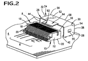
図2は、レセプタクルコネクタ8及びコネクタプラグに対するガイド部材24の相対的位置の後部からの斜視図である。図2に示されるように、ガイド部材24は回路基板4に装着されていて、そのため、ガイド部材24は、レセプタクルコネクタから離れて位置する。すなわち、レセプタクルコネクタ8と接触していないで、該レセプタクルコネクタ8の嵌合面16の前に位置する。図2は、また、回路基板4上の接続トレース6及びレセプタクルコネクタ8の電気的な接点20への接続を示す。図2は、また、打抜きによって側面プレート28内に形成されている側部ロッキングラッチ又は係合タブ53も示す。これらの係合タブ53は、内側、すなわち、ガイド部材24のチャネル80の内部に向って延在し、これらのタブは、プラグ100がガイド部材24内に挿入され、レセプタクルコネクタ8と係合した場合、プラグコネクタ100の側壁部110と摩擦によって接触するような大きさ及び形状を有し、そのように配置されている。図1に示されるように、プラグコネクタは、ガイド部材の係合タブ55が捕捉するその側壁部内に開口部57を設けることができる。
FIG. 2 is a rear perspective view of the
図3は、図1の電子組立体の後部斜視図であり、回路基板4、レセプタクルコネクタ8の後部18を示す。該後部18の接点20は、所定位置に設置され、ラッチされるプラグコネクタ100によって、基板トレース6とプラグコネクタワイヤ101との間に電気接続を確立する。図3の場合には、本考案のプラグコネクタ100は、スプリングアームキャッチ62がプラグコネクタ100の頂部内のスロット102と係合するまで、ガイド部材24を貫通して延在する。図3に示されるように、このキャッチは、遠い方の端部、すなわち、スプリングアーム64がガイド部材24の頂部52の後縁部60から離れる方向に延在する点から最も遠い端部の近くに位置する。このキャッチ−スロット係合装置は、プラグコネクタ100をレセプタクルコネクタ8と嵌合した場合、組立てる人が聞いたり感じたりすることができる、耳で聞くことができる係合「カチッという音」だけではなく、触知可能なカチッという音も発生する。
FIG. 3 is a rear perspective view of the electronic assembly of FIG. 1 and shows the
図4は、ガイド部材24及び該ガイド部材24内に挿入する前のコネクタ100の相対的位置の前部斜視図である。図4は、図面を見やすくするために回路基板4は図示していない。この図は、プラグコネクタ100が、該コネクタ100の本体内に切除、成形又は他の方法で形成され、レセプタクルコネクタと完全に係合した場合に、キャッチ62を受け入れるように位置しているコネクタラッチスロット102を含むことをはっきりと示す。図を見れば、プラグコネクタが、該プラグコネクタ100の前部嵌合面121から外側に延在する前縁部を有する縁部カード120の形をしている好ましい嵌合部を含むことが分かる。
FIG. 4 is a front perspective view of the
縁部カード120は、プラグコネクタ100をレセプタクルコネクタ8内に挿入した場合に、レセプタクルコネクタの接点20と嵌合するために、前縁部に沿って配置されている複数の導電トレース125を有する。プラグコネクタハウジングは、また、嵌合面121から前方に、縁部カード120上に延在する延長部130を含むことができる。図では、この延長部130は、縁部カード120の少なくとも全幅に対して横方向に延在し、縁部カード120の幅より広い幅を有することが好ましい第1のフランジとして図に示されている。この第1のフランジは、まず第一に、縁部カード120が引抜かれるのを防止する働きをし、その内部に支持されている露出した端子の一部をカバーするためにレセプタクルコネクタ8の頂部の一部上を延在する。これは、また、凹部102に対する支持となる。
The
図4は、また、プラグコネクタフランジが、引込面を形成するある角度を有する側面131を有し、そのため、ガイド部材によってプラグコネクタ100をレセプタクルコネクタと容易に整合することができることを最もはっきり示す。第1のフランジは、縁部カード120上の接点が、ガイド部材24又はレセプタクルコネクタ8以外のものと接触するのを防止するために、縁部カード120が嵌合面121から突出している長さよりも長く嵌合面121の前方に延在する好ましい長さを有する。
FIG. 4 also most clearly shows that the plug connector flange has an
図4は、また、ガイド部材24の1つの側面28内に形成されている側面ロッキングラッチ55も示す。この実施形態の場合には、側面ロッキングラッチ55は、対向する側面26の方に延在し、プラグコネクタ100の対応する側面に形成されている対応する側面止金57と係合する側面に小さなタブが形成されるように、ガイド部材24が形成される金属を単に打抜くことによって形成される。プラグコネクタ100が対向するレセプタクルコネクタと完全に係合すると、側面ロッキングラッチ55(ガイド部材24の両方の側面26、28上に形成されていることが好ましい)が、対応する止金57と係合し、プラグコネクタ100をレセプタクルコネクタ8と係合状態に「ラッチ」する。この実施形態の場合のラッチは、レセプタクルコネクタ8によってではなくガイド部材24により行われ、そのため、ワイヤ101による組立体上の歪みは、レセプタクルコネクタ8によってではなくガイド部材24により吸収される。さらに、プラグコネクタ100及びレセプタクルコネクタ8内の接点の任意の整合ずれは、ガイド部材24のこの形態によるプラグ−レセプタクル整合機能によって最小限度まで低減する。
FIG. 4 also shows a
図5は、ガイド部材24内に完全に挿入したコネクタ100の後部斜視図である。この図の場合、ガイド部材キャッチ62は、コネクタ100内のスロット102と相互ロック係合している。スプリングアーム64内の曲がり又は「バイアス」によって、プラグコネクタ100がガイド部材24内に完全に挿入された場合、キャッチ62は、係合スロット102内に下方に押込まれる。同様に、側面ロッキングラッチ55(一方の側面上に示す)も内側に曲がるので、プラグコネクタ100が有意の引出す力が加わらなくても除去されるのを防止するために、プラグコネクタ凹部57内に延在することができる。プラグコネクタ100がこのようにレセプタクルコネクタ8と接続されると、ガイド部材も歪みを除去し、導体が整合する。
FIG. 5 is a rear perspective view of the
図6は、コネクタ整合ガイド24内に設置した場合のコネクタ100の部分断面図である。この図の場合、プラグ係合ラッチ62の相互ロック係合を、図面の右側にはっきり示す。下方にバイアスされていて、コネクタスロット102内に入っている係合ラッチ62は、コネクタ100を整合ガイド24内に保持する働きをすることを理解することができるだろう。また、この図は、コネクタガイドの側面26及び28の底縁部32と接続していて、回路基板又は他の基板4に整合ガイド24を電気的かつ機械的に装着するために使用される2つの装着ポスト70も示す。
FIG. 6 is a partial cross-sectional view of the
図1〜6ではプラグコネクタ100の頂部上に配置されているが、フランジ130は、プラグコネクタ嵌合面121の底部上に設置することもできる。このように設置した場合でも、フランジは、依然としてスタブに対して保護機能を有し、また、レセプタクルコネクタ8の縁部カード収容スロットの下のレセプタクルコネクタ8の底部に沿って形成されている凹部内に収容する整合機能を有する。
1 to 6 are arranged on the top of the
図7及び8は、本考案の原理によって組立てた回路基板上で垂直に使用するためのプラグコネクタの他の実施形態200である。これらの図に示されるように、レセプタクルコネクタ201は、回路基板202に対して垂直に面実装されるコネクタである。コネクタ201は、絶縁性ハウジング204を有し、複数の導電性端子206を支持する。該端子206は、回路基板202の表面上のパッド又はトレースにはんだ付されるテール部208を含む。導電性ガイド部材210は、コネクタ202と一緒に使用するためのものであり、そこから横方向に延在する2つの側部プレート213を有する頂部プレート212を含むほぼU字形をしていることが分かる。これら3つのプレートは、協働して、レセプタクルコネクタ201の周囲及び上を部分的に延在するチャネル215を画定する。ガイド部材の頂部プレート212は、スロットを含み、キャッチ部材220が延在する凹部218を有する。このキャッチ部材は、第1の実施形態と同じ方法で、プラグコネクタハウジング250上のスロット(図示せず)と係合することが好ましい曲げ部221を有する。
7 and 8 are other embodiments 200 of plug connectors for vertical use on circuit boards assembled according to the principles of the present invention. As shown in these drawings, the receptacle connector 201 is a connector that is surface-mounted perpendicular to the circuit board 202. The connector 201 has an insulating housing 204 and supports a plurality of conductive terminals 206. The terminal 206 includes a
この実施形態の場合には、プラグコネクタ240は、大部分が、単に垂直方向に対して向けるためのものであって、縁部カード及び第1のフランジが延在する絶縁性ハウジング250を有する。第1のフランジの一部は、レセプタクルコネクタ201の露出する端子の上を延在し、垂直ガイド部材のキャッチ部材220と係合するためのスロットを有する。
In this embodiment, the plug connector 240 has an
図9は、本考案の原理によって組立てられたプラグコネクタの他の実施形態を含む他の電子組立体である。この組立体においては、シュラウド(又はガイド部材)1100は、間に間隔を有する2つの側壁部1104、1105を相互に接続する頂壁部1102を有する。シュラウド1100は、端部から見た場合ほぼ逆U字形をしていて、回路基板1110に装着されるレセプタクルコネクタ1150から離れている回路基板1110上に位置する。レセプタクルコネクタ1105は、図1〜6に示し説明したレセプタクルコネクタ8と類似の形をしていて、そのカード収容スロットの下のその底面に沿って、及び、レセプタクルコネクタ1105の底面の下に開口部又は凹部を含む。スロットは、プラグコネクタ1200でそのブレード部として使用される回路カードの前縁部を収容する。シュラウド1100は、プラグコネクタ1200を回路基板コネクタ1150と係合するために案内することができる中空チャネル1106を含む。
FIG. 9 is another electronic assembly including another embodiment of a plug connector assembled according to the principles of the present invention. In this assembly, the shroud (or guide member) 1100 has a
シュラウド1100は、また、嵌合の後でプラグコネクタ1200を所定位置に保持する働きもする。この点について、シュラウド1100は、該シュラウドの頂壁部1102の前方に延在する細長い延長部1117を含み、さらに、シュラウド1100の側壁部1104、1105内に配置されていて、前方に縦方向に延在する1つ又は複数の整合スロット1135を含むことが好ましい。その目的については、以下に更に詳細に説明する。プラグコネクタ1200を案内するための追加手段1119もシュラウド1100上に設置することができ、内側に曲がり、側壁部1104、1105から所定の距離だけ延在するタブ1118の形をとることができる。
The
図13及び15に最もよく示されるように、プラグコネクタ1200は、ほぼ多角形をしていて、図面では、頂面1202、2つの側壁部1204、1205、底面1206及び後面1208を含む実線の長方形で示してある。ケーブルは、通常、後面1208から外に出るが、図面を見やすくするために省略してある。コネクタの前端部1210は、プラグコネクタ1200の嵌合端部を画定していて、図9〜13に示されるような用途の場合には、プラグコネクタ1200は、通常は回路カード1214の前縁部の形をしている前方に突出している嵌合ブレード1212を含む前部嵌合面1211を含むことが好ましい。頂面1202(及び、図面では底面1206)は、前部面1211から前方に延在し、回路カード1212上に位置し、該回路カードから離れている第1のフランジの形をしている延長部1215を有することができる。この実施形態はもう1つの延長部を含むことが好ましく、図12及び13に最もよく示されるように、この延長部は、同様に、前部面1211から前方に延在し、回路カード1214及び第1のフランジ1215の下に位置し、これらの部材から離れている第2のフランジ1216の形をしている。このタイプの装置の場合には、2つのフランジ1215、1216を「側面に位置する」回路カード1212と見なすことができる。
As best shown in FIGS. 13 and 15, the
シュラウド圧着タブ1117は、若干のバイアスを与えるために下方に曲がっていて、そのため、嵌合コネクタ1200の頂面1202、特に、その頂部延長部1215とスライド又は端接によって接触する。図13はこのタイプの係合を最もはっきり示し、頂部フランジ1215は、シュラウド圧着タブ1117の止金部と係合するように、頂部フランジ1215の前端部から特定の距離だけ離れている横方向のスロット又は凹部1214を含むことができる。この係合は、プラグコネクタ1200をレセプタクルコネクタ1150と嵌合状態に保持するのを助け、また、オペレータが2つのコネクタ1200、1150間の係合が完了したのを確認するのを助ける働きをする。その下向きのバイアスを含む圧着タブ1117は、聞いたり感じたりすることができる両方の方法で、凹部1214内に「カチッ」と係合する。そのため、オペレータは、係合を感じるばかりでなく、係合を「耳で聞く」こともできる。
The
シュラウド100は、さらに、ラッチ機構の一部としてプラグコネクタ200上に形成されていることが好ましい、ラグ1220のような手段によって係合する、その頂壁部102内に配置されている1つ又は複数のスロット又は凹部1130を含むことができる。これらのラグ220は、以下に更に詳細に説明するように、別の基部又はアンカー及び作動部を形成するために、あるラインに沿って自分自身の上で曲がっている、図ではある長さのシートメタルから形成されているプッシュタイプのボタン1225によって、スロット1130と係合したり、係合から外れたりする。
The
すでに説明したように、シュラウド1100は、また、該シュラウドの側壁部1104、1105で、その外側を向いている縁部に沿って形成されている一対の整合スロット1135を含むことができる。これらのノッチ1135は、プラグコネクタハウジング1200の外部上に形成されているラグ1226として示される対応する構造体と係合する。これらのラグ1226は、対応するシュラウドの整合スロット1135内に収容されている中央脚部1227、及び、該中央脚部1227に垂直な基部1228を形成している他の2つの脚部を含み、側面から見た場合ほぼT字形をしている。基部1228は、側壁部1104、1105の縁部と端接した場合、停止部材としての働きをする。本考案の場合には、シュラウド100のタブ1118は、プラグコネクタ外部に沿って縦方向に延在するノッチ1207内に収容され、これらのタブ1118及びノッチ1207は、シュラウド1100の内部でまず第一に、プラグコネクタ1200をある方向に向け、位置決めする働きをし、次に、ノッチ1135及びラグ1226は協働して、レセプタクルコネクタ1150のカード収容スロットに対向して、プラグコネクタ1200の回路カード1212をある方向に向ける。
As previously described, the
図14〜19は、本考案の原理によって組立てられたプラグコネクタ300の他の実施形態である。図14では、プラグコネクタ300は、突起嵌合ブレード304が延在し、他の実施形態においては回路カード305として示される前部嵌合面302を備える絶縁性ハウジング301を含む。回路カードは、すでに参照符号8及び1150で示すタイプの対向するレセプタクルコネクタの対応するスロットに容易に入れることができるように、図に示されるようなある角度を有するか、又は、面取りすることができる前縁部306を有する。プラグコネクタ300は、プラグコネクタ本体部309、特に、前面302から前方に延在する第1及び第2の(又は頂部及び底部)フランジ310、312を含む。
14-19 are other embodiments of a
図15に示されるように、頂部及び底部フランジ310、312は、スタブ及び偶発的なショートから回路カードの前縁部306を保護するために、回路カード305の前縁部306を越えて、あらかじめ選択した距離Dをそれぞれ延在することが好ましい。頂部フランジ310は、その側縁部316に沿ってある角度を有することが好ましく、これらのある角度を有する縁部は、ガイド部材及びレセプタクルコネクタ又は両方に挿入された場合、フランジ310及びプラグコネクタ300に「引込」手段を提供する。図18に最もよく示されるように、頂部フランジ310は、回路カード305の幅より広い幅を有することが好ましいが、底部フランジ312は、回路カード305の幅より狭い幅を有することが好ましい。そのため底部フランジ310は、本考案のプラグコネクタと一緒に使用するためのレセプタクルコネクタの底面に沿っている収容スペース内に容易に挿入することができる。この距離の違いによって、底面フランジ310が対向するレセプタクルコネクタの脚部と衝突する恐れが少なくなる。回路カード305は、これら2つのフランジ310、312間に配置されていて、各フランジは、水平方向を向いていようが、垂直方向を向いていようが、回路カード305を保護する手段を提供する。
As shown in FIG. 15, the top and
この実施形態300は、また、コネクタ本体部309の一部として形成されていることが好ましいフレーム部材326を含むラッチ機構325を含む。このフレーム部材326は、ラッチ部材328を収容するスロット327を画定する。図16及び17は、ラッチ部材328を最もよく示す。このラッチ部材328は、その前縁部329に沿ってそれ自身の上で折曲がっている1枚の金属片から形成することができる。この折曲がりが、金属片を2つの部分に分割する。この第1の部分は、ほぼ平らな基部又はアンカー部330及びある輪郭を有する作動部331である。基部は、側縁部333に沿って形成されていて、主として、ラッチ部材328をプラグコネクタ300上の所定の位置に保持するために、フレーム部材スロット327の内側壁部340内へそれら自身を埋設、又は「削る」1つ又は複数の干渉突起332を有する。
This
1つ又は複数の上を向いているラッチタブ346が、ラッチ部材328内に形成されていて、これらのタブ346は、図11に最もよく示されるように、ガイド部材内に形成されている対応する開口部又は凹部と係合する。作動部331は、若干上向きの角度で曲がっていて、そのためフレーム部材326の制約内で曲がることができる。この点に関して、スロット327は、図19に最もよく示されるように、ラッチ部材328の側縁部333及び削り突起332を収容する内部溝部又はチャネル340を含む。基部330は、作動部331より若干大きく、そのため、この基部はフレーム部材内で干渉嵌(はめ)合いを形成し、それにより、作動部はフレーム部材326内の所定位置で容易に上下に曲がることができる。作動部331を捕捉するために、その後端部335は、側面に突出している1つ又は複数のタブ336を含むことができ、これらのタブは、スロット327の内面340に沿って形成されている肩部329によって、その可能な垂直方向の運動(上下運動)中に捕捉される。肩部329の下のエリアは、作動部331のボタン部326を下に押した場合、タブ336がうまく入り、また、湾曲することができるように、341の所で凹んでいる。
One or more upwardly facing
フレーム部材326の前端部345は、プラグコネクタの本体部の頂面上に中空でない端接部として形成することができ、また、ある角度を有する側縁部346を有することもできる。したがって、この前端部345は、すでに説明した本体部のノッチ1207並びに頂部及び底部フランジの他に、他のキーイング機能としての働きをすることができる。このようなキーイング機能を実行するために、ガイド部材は、フレーム部材の前端部345を案内し、収容するチャネルを含むことができる。頂部フランジ310は、また、該頂部フランジ310の前縁部から離れている横方向の凹部311を備えることができる。この凹部は、すでに説明したように、ガイド部材の圧着タブの対応する止金を収容する。
The
この実施形態の場合には、回路カードの整合手段350は、若干違う形をしている。この整合手段は、プラグコネクタ本体部309の側面から外側に延在する突出ラグ351を含むが、該ラグは1つの突起ではなく、コネクタ本体部309aの後部は幅が広くなっていて、そのため、2つの停止面352がラグ351の各側面上に画定される。T字形全体は同じままであるが、停止面がプラグコネクタ内に切込んでいるという点で、ラグ/停止部材は、剪(せん)断力に対して強化されている。この点に関して、ラグ351の前のエリアは、コネクタ本体部の拡大エリア209aに対して凹んでいると見なすことができる。
In this embodiment, the circuit card matching means 350 has a slightly different shape. This alignment means includes a protruding
Claims (18)
コネクタハウジングであって、絶縁性本体部を含み、前記コネクタハウジングの本体部が前面を含むコネクタハウジングと、
嵌合コネクタと嵌合するための接点を備える前縁部を含む嵌合ブレード部であって、該嵌合ブレード部の前縁部が、あらかじめ選択した長さだけ前記コネクタ本体部の前面から前方に延在している嵌合ブレード部と、
前記接点に終端する複数のワイヤとを備え、
前記コネクタハウジング本体部が、該コネクタハウジング本体部から第1のあらかじめ選択した距離だけ前方に延在し、回路カードから離れている第1のフランジと、前記コネクタハウジング本体部から第2のあらかじめ選択した距離だけ前方に延在し、前記嵌合ブレード部及び前記第1のフランジから離れている第2のフランジとを含むプラグコネクタ。 A plug connector for connecting a wire to a mating connector,
A connector housing comprising an insulating body, wherein the body of the connector housing includes a front surface;
A mating blade portion including a front edge portion provided with a contact for mating with a mating connector, wherein the front edge portion of the mating blade portion is forward from the front surface of the connector main body portion by a preselected length. A mating blade portion extending to
A plurality of wires terminating at the contacts;
A first flange extending forward from the connector housing body by a first preselected distance and spaced from the circuit card; and a second preselected from the connector housing body. A plug connector including a second flange extending forwardly by a distance and spaced from the mating blade portion and the first flange.
Applications Claiming Priority (4)
| Application Number | Priority Date | Filing Date | Title |
|---|---|---|---|
| US63701304P | 2004-12-17 | 2004-12-17 | |
| US65567305P | 2005-02-23 | 2005-02-23 | |
| US70469805P | 2005-08-02 | 2005-08-02 | |
| PCT/US2005/044757 WO2006065681A1 (en) | 2004-12-17 | 2005-12-09 | Plug connector with mating protection and alignment means |
Publications (1)
| Publication Number | Publication Date |
|---|---|
| JP3142836U true JP3142836U (en) | 2008-07-03 |
Family
ID=35929966
Family Applications (1)
| Application Number | Title | Priority Date | Filing Date |
|---|---|---|---|
| JP2008600009U Expired - Lifetime JP3142836U (en) | 2004-12-17 | 2005-12-09 | Plug connector with mating protection and alignment means |
Country Status (7)
| Country | Link |
|---|---|
| US (1) | US7303438B2 (en) |
| EP (1) | EP1834382B1 (en) |
| JP (1) | JP3142836U (en) |
| KR (1) | KR200438440Y1 (en) |
| DE (1) | DE602005007068D1 (en) |
| TW (2) | TWI326506B (en) |
| WO (1) | WO2006065681A1 (en) |
Cited By (2)
| Publication number | Priority date | Publication date | Assignee | Title |
|---|---|---|---|---|
| JP2013522848A (en) * | 2010-03-19 | 2013-06-13 | モレックス インコーポレイテド | Plug connector with improved structure |
| EP3000156B1 (en) | 2013-05-21 | 2018-10-17 | Continental Automotive GmbH | Contact device for establishing an electric contact between a printed circuit board and an electromotor |
Families Citing this family (111)
| Publication number | Priority date | Publication date | Assignee | Title |
|---|---|---|---|---|
| US6776660B1 (en) | 2003-04-30 | 2004-08-17 | Japan Aviation Electronics Industry, Limited | Connector |
| EP1774624A1 (en) * | 2004-07-07 | 2007-04-18 | Molex Incorporated | Keyed housing for use with small size plug connectors |
| CN101032060B (en) * | 2004-07-07 | 2010-08-25 | 莫莱克斯公司 | Edge card connector with key mechanism for proper connection |
| US7448897B2 (en) * | 2004-12-17 | 2008-11-11 | Molex Incorporated | Plug connector with mating protection |
| US7413461B2 (en) * | 2004-12-17 | 2008-08-19 | Molex Incorporated | Connector guide with latch and connectors therefor |
| US7175444B2 (en) * | 2005-02-23 | 2007-02-13 | Molex Incorporated | Plug connector and construction therefor |
| US7344409B2 (en) * | 2005-02-23 | 2008-03-18 | Molex Incorporated | Connector guide member |
| US7540788B2 (en) * | 2007-01-05 | 2009-06-02 | Apple Inc. | Backward compatible connector system |
| US8095713B2 (en) * | 2007-09-04 | 2012-01-10 | Apple Inc. | Smart cables |
| US7445503B1 (en) * | 2007-09-12 | 2008-11-04 | Hon Hai Precision Ind. Co., Ltd. | Electrical connector with shell |
| US20090088011A1 (en) * | 2007-10-02 | 2009-04-02 | Yen-Chung Hsieh | Cable connector module |
| US7798821B2 (en) * | 2008-02-01 | 2010-09-21 | Hon Hai Precision Ind. Co., Ltd | Cable assembly with an organizer for adjusting the cable outlet |
| CN201178180Y (en) | 2008-02-01 | 2009-01-07 | 富士康(昆山)电脑接插件有限公司 | Cable Connector Assembly |
| US7927150B2 (en) * | 2008-10-23 | 2011-04-19 | Tyco Electronics Corporation | Connectors including spring tabs for holding a contact module |
| US7896683B1 (en) * | 2008-10-23 | 2011-03-01 | Tyco Electronics Corporation | Connector assemblies configured to prevent damage to contacts during mating and demating |
| US7892045B2 (en) * | 2008-10-23 | 2011-02-22 | Tyco Electronics Corporation | Connector having interlocking components |
| US7601010B1 (en) | 2009-01-12 | 2009-10-13 | Hon Hai Precision Inc. Co., Ltd. | Plug connector with improved cable arrangement and having retaining arrangement securely retaining mating substrate therein |
| CN102341970B (en) * | 2009-01-20 | 2014-04-30 | 莫列斯公司 | Plug connectors with external EMI shielding |
| CN201498685U (en) * | 2009-03-26 | 2010-06-02 | 富士康(昆山)电脑接插件有限公司 | Cable Connector Assembly |
| JP2010251319A (en) | 2009-04-15 | 2010-11-04 | Chou Hsien Tsai | Socket structure with duplex electrical connection |
| US7909661B2 (en) | 2009-04-27 | 2011-03-22 | Hon Hai Precision Ind. Co., Ltd. | Plug connector with improved cable arrangement and having retaining arrangement securely retaining mating substrate therein |
| CN101882726B (en) * | 2009-05-06 | 2012-07-18 | 富士康(昆山)电脑接插件有限公司 | Electric connector assembly |
| US7878865B2 (en) * | 2009-06-08 | 2011-02-01 | International Business Machines Corporation | Locking connector for engaging a USB receptacle |
| US7891986B2 (en) * | 2009-07-13 | 2011-02-22 | Hon Hai Precision Ind. Co., Ltd. | Cable assembly with EMI protection |
| PL2290758T3 (en) * | 2009-08-26 | 2017-04-28 | Wieland Electric Gmbh | Industry connector |
| CN201741902U (en) * | 2009-12-08 | 2011-02-09 | 富士康(昆山)电脑接插件有限公司 | Cable connector assembly |
| CN102208726B (en) * | 2010-03-29 | 2013-05-08 | 富士康(昆山)电脑接插件有限公司 | Cable connector assembly |
| US8267718B2 (en) | 2010-04-07 | 2012-09-18 | Panduit Corp. | High data rate electrical connector and cable assembly |
| CN201708379U (en) | 2010-04-07 | 2011-01-12 | 富士康(昆山)电脑接插件有限公司 | Cable Connector Assembly |
| CN201774051U (en) | 2010-05-12 | 2011-03-23 | 富士康(昆山)电脑接插件有限公司 | Cable Connector Assembly |
| CN201829646U (en) * | 2010-05-31 | 2011-05-11 | 富士康(昆山)电脑接插件有限公司 | Electric connector component |
| CN202042687U (en) * | 2011-01-14 | 2011-11-16 | 富士康(昆山)电脑接插件有限公司 | Electrical Connector Assembly |
| CN103050834B (en) | 2011-10-12 | 2015-05-06 | 富士康(昆山)电脑接插件有限公司 | Cable connector assembly |
| JP2013232312A (en) * | 2012-04-27 | 2013-11-14 | Jst Mfg Co Ltd | Card member, card edge connector, and manufacturing method of card member |
| US9263818B2 (en) * | 2013-01-04 | 2016-02-16 | Google Inc. | Methods and apparatus related to receptacles and releasable connectors |
| CN203589367U (en) * | 2013-05-24 | 2014-05-07 | 富士康(昆山)电脑接插件有限公司 | Electric connector combination and electric connector |
| CN104348057A (en) * | 2013-07-30 | 2015-02-11 | 富士康(昆山)电脑接插件有限公司 | Cable connector assembly |
| US8821181B1 (en) | 2013-10-09 | 2014-09-02 | Google Inc. | Electrical connector |
| US9356372B2 (en) * | 2013-11-22 | 2016-05-31 | Intel Corporation | Techniques to convert signals routed through a fabric cable assembly |
| WO2015080997A1 (en) * | 2013-11-27 | 2015-06-04 | Fci Asia Pte. Ltd | Electrical connector including guide member |
| US9257767B2 (en) * | 2014-01-18 | 2016-02-09 | Advanced Micro Devices, Inc. | Connector adaptor to facilitate coupling of a mating card edge with a female card-edge connector |
| JP2017533563A (en) * | 2014-11-03 | 2017-11-09 | スリーエム イノベイティブ プロパティズ カンパニー | connector |
| US9726830B1 (en) | 2016-06-28 | 2017-08-08 | Senko Advanced Components, Inc. | Connector and adapter system for two-fiber mechanical transfer type ferrule |
| US10078188B1 (en) | 2016-12-05 | 2018-09-18 | Senko Advanced Components, Inc. | Springless push/pull fiber optic connector |
| US10228521B2 (en) | 2016-12-05 | 2019-03-12 | Senko Advanced Components, Inc. | Narrow width adapters and connectors with modular latching arm |
| EP3530089A4 (en) | 2017-01-12 | 2020-06-03 | Samtec, Inc. | Cage with an attached heatsink |
| TWM551363U (en) | 2017-01-23 | 2017-11-01 | 宣德科技股份有限公司 | Improvement of the connector structure |
| US10725248B2 (en) | 2017-01-30 | 2020-07-28 | Senko Advanced Components, Inc. | Fiber optic receptacle with integrated device therein incorporating a behind-the-wall fiber optic receptacle |
| US11333836B2 (en) | 2017-01-30 | 2022-05-17 | Senko Advanced Components, Inc. | Adapter for optical connectors |
| US10185100B2 (en) * | 2017-01-30 | 2019-01-22 | Senko Advanced Components, Inc | Modular connector and adapter assembly using a removable anchor device |
| US10871619B2 (en) * | 2017-01-30 | 2020-12-22 | Senko Advanced Components, Inc. | Cassette assembly for a plural of fiber optic receptacles |
| US10444444B2 (en) | 2017-01-30 | 2019-10-15 | Senko Advanced Components, Inc. | Remote release tab connector assembly |
| US10416394B2 (en) | 2017-01-30 | 2019-09-17 | Senko Advanced Components, Inc. | Fiber optic receptacle with integrated device therein |
| WO2018140981A1 (en) | 2017-01-30 | 2018-08-02 | Senko Advanced Components, Inc. | Optical connectors with reversible polarity |
| CN207753259U (en) * | 2017-03-16 | 2018-08-21 | 立讯精密工业股份有限公司 | Plug and electric coupler component |
| CN108808380A (en) * | 2017-05-03 | 2018-11-13 | 富士康(昆山)电脑接插件有限公司 | Electric coupler component |
| US10718910B2 (en) | 2017-05-03 | 2020-07-21 | Senko Advanced Components, Inc | Field terminated ruggedized fiber optic connector system |
| WO2019010050A1 (en) | 2017-07-07 | 2019-01-10 | Amphenol Corporation | Asymmetric latches for pluggable transceivers |
| US10281669B2 (en) | 2017-07-14 | 2019-05-07 | Senko Advance Components, Inc. | Ultra-small form factor optical connectors |
| US11822133B2 (en) | 2017-07-14 | 2023-11-21 | Senko Advanced Components, Inc. | Ultra-small form factor optical connector and adapter |
| US12001064B2 (en) | 2017-07-14 | 2024-06-04 | Senko Advanced Components, Inc. | Small form factor fiber optic connector with multi-purpose boot |
| US10718911B2 (en) | 2017-08-24 | 2020-07-21 | Senko Advanced Components, Inc. | Ultra-small form factor optical connectors using a push-pull boot receptacle release |
| WO2019028373A1 (en) | 2017-08-03 | 2019-02-07 | Amphenol Corporation | Cable connector for high speed interconnects |
| US10641972B2 (en) | 2017-08-17 | 2020-05-05 | Senko Advanced Components, Inc | Anti-jam alignment sleeve holder or connector housing for a ferrule assembly |
| US11002923B2 (en) | 2017-11-21 | 2021-05-11 | Senko Advanced Components, Inc. | Fiber optic connector with cable boot release having a two-piece clip assembly |
| CN115201974B (en) * | 2017-12-19 | 2024-04-30 | 美国康涅克有限公司 | Miniature duplex connector with push-pull polarity mechanism and carrier |
| WO2019183070A2 (en) | 2018-03-19 | 2019-09-26 | Senko Advanced Components, Inc. | Removal tool for removing a plural of micro optical connectors from an adapter interface |
| WO2019191522A1 (en) | 2018-03-28 | 2019-10-03 | Senko Advanced Components Inc | Small form factor fiber optic connector with multi-purpose boot |
| WO2019195319A1 (en) | 2018-04-02 | 2019-10-10 | Ardent Concepts, Inc. | Controlled-impedance compliant cable termination |
| CN208738551U (en) | 2018-05-30 | 2019-04-12 | 立讯精密工业股份有限公司 | High-density MINI chip side high-speed connector and printed circuit board layout structure |
| CN112088327A (en) | 2018-07-15 | 2020-12-15 | 扇港元器件股份有限公司 | Subminiature Optical Connectors and Adapters |
| US10444441B1 (en) | 2018-08-10 | 2019-10-15 | Senko Advanced Components, Inc. | Pivotable housing for a fiber optic connector |
| CN112534324A (en) | 2018-08-13 | 2021-03-19 | 扇港元器件股份有限公司 | Cable sleeve assembly for releasing fiber optic connectors from receptacles |
| US10921531B2 (en) | 2018-09-12 | 2021-02-16 | Senko Advanced Components, Inc. | LC type connector with push/pull assembly for releasing connector from a receptacle using a cable boot |
| WO2020055440A1 (en) | 2018-09-12 | 2020-03-19 | Senko Advanced Componetns, Inc. | Lc type connector with clip-on push/pull tab for releasing connector from a receptacle using a cable boot |
| US10921530B2 (en) | 2018-09-12 | 2021-02-16 | Senko Advanced Components, Inc. | LC type connector with push/pull assembly for releasing connector from a receptacle using a cable boot |
| US10797417B2 (en) | 2018-09-13 | 2020-10-06 | Amphenol Corporation | High performance stacked connector |
| CN208862209U (en) | 2018-09-26 | 2019-05-14 | 安费诺东亚电子科技(深圳)有限公司 | A kind of connector and its pcb board of application |
| US11806831B2 (en) | 2018-11-21 | 2023-11-07 | Senko Advanced Components, Inc. | Fixture and method for polishing fiber optic connector ferrules |
| US11175464B2 (en) | 2018-11-25 | 2021-11-16 | Senko Advanced Components, Inc. | Open ended spring body for use in an optical fiber connector |
| US11837808B2 (en) * | 2018-12-28 | 2023-12-05 | Autonetworks Technologies, Ltd. | Board connector and device |
| WO2020154507A1 (en) | 2019-01-25 | 2020-07-30 | Fci Usa Llc | I/o connector configured for cable connection to a midboard |
| CN117175250A (en) | 2019-01-25 | 2023-12-05 | 富加宜(美国)有限责任公司 | I/O connector configured for cabling to the midplane |
| US11437762B2 (en) | 2019-02-22 | 2022-09-06 | Amphenol Corporation | High performance cable connector assembly |
| US11579379B2 (en) | 2019-03-28 | 2023-02-14 | Senko Advanced Components, Inc. | Fiber optic adapter assembly |
| US12038613B2 (en) | 2019-03-28 | 2024-07-16 | Senko Advanced Components, Inc. | Behind-the-wall optical connector and assembly of the same |
| US11340406B2 (en) | 2019-04-19 | 2022-05-24 | Senko Advanced Components, Inc. | Small form factor fiber optic connector with resilient latching mechanism for securing within a hook-less receptacle |
| DE102019112236A1 (en) * | 2019-05-10 | 2020-11-26 | Phoenix Contact Gmbh & Co. Kg | Fastening device for fastening a connection arrangement to a circuit board |
| US11314024B2 (en) | 2019-06-13 | 2022-04-26 | Senko Advanced Components, Inc. | Lever actuated latch arm for releasing a fiber optic connector from a receptacle port and method of use |
| TWM584035U (en) * | 2019-06-18 | 2019-09-21 | 貝爾威勒電子股份有限公司 | Plug connector with protective member for replacing gold finger of circuit board |
| CN114600018B (en) | 2019-07-23 | 2024-04-09 | 扇港元器件有限公司 | Ultra-small receptacle for receiving a fiber optic connector opposite a ferrule assembly |
| US10855028B1 (en) * | 2019-07-29 | 2020-12-01 | Te Connectivity Corporation | Plug connector |
| CN114788097A (en) | 2019-09-19 | 2022-07-22 | 安费诺有限公司 | High speed electronic system with midplane cable connector |
| CN119447888A (en) | 2019-09-27 | 2025-02-14 | 富加宜(美国)有限责任公司 | High-performance stacking connectors |
| CN113258325A (en) | 2020-01-28 | 2021-08-13 | 富加宜(美国)有限责任公司 | High-frequency middle plate connector |
| TWI730712B (en) | 2020-04-09 | 2021-06-11 | 財團法人工業技術研究院 | High speed connector for reducing crosstalk effect and insulated plastic element |
| JP7454995B2 (en) * | 2020-05-11 | 2024-03-25 | モレックス エルエルシー | Connectors and connector pairs |
| US11728585B2 (en) | 2020-06-17 | 2023-08-15 | Amphenol East Asia Ltd. | Compact electrical connector with shell bounding spaces for receiving mating protrusions |
| TWI861425B (en) * | 2020-07-28 | 2024-11-11 | 香港商安費諾(東亞)有限公司 | Electrical connector and method of mating a plug connector and a receptacle connector |
| KR20220046883A (en) | 2020-10-08 | 2022-04-15 | 삼성전자주식회사 | Electronic device including host connector and memory device |
| CN120357236A (en) * | 2020-12-16 | 2025-07-22 | 东莞立讯技术有限公司 | Board end connector and connector assembly |
| US11515666B2 (en) * | 2020-12-16 | 2022-11-29 | Te Connectivity Solutions Gmbh | System for vehicle battery charging around charge-adverse time periods |
| CN119864683A (en) | 2020-12-16 | 2025-04-22 | 东莞立讯技术有限公司 | Wire end connector and connector assembly |
| US11367979B1 (en) | 2020-12-28 | 2022-06-21 | Industrial Technology Research Institute | Terminal components of connector and connector structure |
| US11569613B2 (en) | 2021-04-19 | 2023-01-31 | Amphenol East Asia Ltd. | Electrical connector having symmetrical docking holes |
| US12212100B2 (en) | 2021-04-30 | 2025-01-28 | Amphenol Corporation | Miniaturized high speed connector |
| US12176650B2 (en) * | 2021-05-05 | 2024-12-24 | Amphenol East Asia Limited (Hong Kong) | Electrical connector with guiding structure and mating groove and method of connecting electrical connector |
| JP7662287B2 (en) * | 2021-06-25 | 2025-04-15 | TE Connectivity Japan合同会社 | connector |
| TWM631360U (en) * | 2022-01-25 | 2022-09-01 | 貝爾威勒電子股份有限公司 | Plug connector with protective structure |
| US20230335946A1 (en) * | 2022-04-15 | 2023-10-19 | Mantis Yesway Co., Ltd. | Connector guide device |
| WO2026069155A1 (en) * | 2024-09-26 | 2026-04-02 | 3M Innovative Properties Company | Electrical connector and electrical connector assembly |
Family Cites Families (24)
| Publication number | Priority date | Publication date | Assignee | Title |
|---|---|---|---|---|
| JP2787307B2 (en) * | 1987-07-17 | 1998-08-13 | アンプ インコーポレーテッド | connector |
| US4878848A (en) | 1988-07-14 | 1989-11-07 | Independent Technologies, Inc. | 110 Block adapter |
| US4968260A (en) * | 1989-11-22 | 1990-11-06 | Independent Technologies, Inc. | Bix block adapter |
| US5332397A (en) * | 1993-01-15 | 1994-07-26 | Independent Technologies, Inc. | Test cord apparatus |
| JPH07176336A (en) * | 1993-09-30 | 1995-07-14 | Siemon Co:The | Electrically expanded wiring block with break test capability |
| JP3094150B2 (en) | 1996-04-30 | 2000-10-03 | 矢崎総業株式会社 | Switch box mounting structure |
| US5957727A (en) * | 1996-12-12 | 1999-09-28 | The Whitaker Corporation | Electrical connector assembly |
| US6007359A (en) | 1997-11-25 | 1999-12-28 | Itt Manufacturing Enterprises, Inc. | Receptacle connector |
| US6186808B1 (en) | 1998-04-27 | 2001-02-13 | Krone Gmbh | High density high performance telecommunications/data link and connector with tap and contact displacement assembly |
| US6435897B1 (en) | 2000-04-10 | 2002-08-20 | Storcase Technology, Inc. | Compact PCI connector guide |
| US6431887B1 (en) * | 2000-05-31 | 2002-08-13 | Tyco Electronics Corporation | Electrical connector assembly with an EMI shielded plug and grounding latch member |
| US6666692B2 (en) | 2000-12-21 | 2003-12-23 | Hon Hai Precision Ind. Co., Ltd. | Electrical connector |
| US6755680B2 (en) | 2001-01-19 | 2004-06-29 | Autonetworks Technologies, Ltd. | Fixture device for use in connection of flat wire member with terminal connector |
| US6582252B1 (en) * | 2002-02-11 | 2003-06-24 | Hon Hai Precision Ind. Co., Ltd. | Termination connector assembly with tight angle for shielded cable |
| JP2003243093A (en) | 2002-02-21 | 2003-08-29 | Yazaki Corp | USB connector |
| US6619989B1 (en) * | 2002-05-30 | 2003-09-16 | Hon Hai Precision Ind. Co., Ltd. | Cable connector having integrally formed metal latch and cable strain relief |
| US6585537B1 (en) * | 2002-10-24 | 2003-07-01 | Hon Hai Precision Ind. Co., Ltd. | Cable end connector with locking member |
| US7413461B2 (en) | 2004-12-17 | 2008-08-19 | Molex Incorporated | Connector guide with latch and connectors therefor |
| US7448897B2 (en) | 2004-12-17 | 2008-11-11 | Molex Incorporated | Plug connector with mating protection |
| US7226314B2 (en) | 2005-02-23 | 2007-06-05 | Molex Incorporated | Connector and guide placement member |
| US7344409B2 (en) | 2005-02-23 | 2008-03-18 | Molex Incorporated | Connector guide member |
| US7175444B2 (en) | 2005-02-23 | 2007-02-13 | Molex Incorporated | Plug connector and construction therefor |
| US7128595B2 (en) * | 2005-03-23 | 2006-10-31 | Amphenol Corporation | Electrical connector with positive lock |
| US7163408B1 (en) * | 2005-11-16 | 2007-01-16 | Jess-Link Products Co., Ltd. | Electrical connector |
-
2005
- 2005-10-07 US US11/245,578 patent/US7303438B2/en not_active Expired - Lifetime
- 2005-12-09 JP JP2008600009U patent/JP3142836U/en not_active Expired - Lifetime
- 2005-12-09 DE DE602005007068T patent/DE602005007068D1/en not_active Expired - Fee Related
- 2005-12-09 KR KR2020077000012U patent/KR200438440Y1/en not_active Expired - Lifetime
- 2005-12-09 EP EP05853626A patent/EP1834382B1/en not_active Expired - Lifetime
- 2005-12-09 WO PCT/US2005/044757 patent/WO2006065681A1/en not_active Ceased
- 2005-12-16 TW TW094144711A patent/TWI326506B/en not_active IP Right Cessation
- 2005-12-16 TW TW094144713A patent/TWI325201B/en not_active IP Right Cessation
Cited By (2)
| Publication number | Priority date | Publication date | Assignee | Title |
|---|---|---|---|---|
| JP2013522848A (en) * | 2010-03-19 | 2013-06-13 | モレックス インコーポレイテド | Plug connector with improved structure |
| EP3000156B1 (en) | 2013-05-21 | 2018-10-17 | Continental Automotive GmbH | Contact device for establishing an electric contact between a printed circuit board and an electromotor |
Also Published As
| Publication number | Publication date |
|---|---|
| TWI325201B (en) | 2010-05-21 |
| TWI326506B (en) | 2010-06-21 |
| EP1834382B1 (en) | 2008-05-21 |
| US7303438B2 (en) | 2007-12-04 |
| KR200438440Y1 (en) | 2008-02-14 |
| KR20070001248U (en) | 2007-11-29 |
| EP1834382A1 (en) | 2007-09-19 |
| TW200638614A (en) | 2006-11-01 |
| TW200638615A (en) | 2006-11-01 |
| DE602005007068D1 (en) | 2008-07-03 |
| WO2006065681A1 (en) | 2006-06-22 |
| US20060160429A1 (en) | 2006-07-20 |
Similar Documents
| Publication | Publication Date | Title |
|---|---|---|
| JP3142836U (en) | Plug connector with mating protection and alignment means | |
| JP3142837U (en) | Plug connector with mating protection | |
| JP3121388U (en) | Plug connector and assembly | |
| JP3142283U (en) | Connector guide with latch and connector therefor | |
| JP4522144B2 (en) | Electrical connector | |
| USRE43427E1 (en) | Plug connector with mating protection | |
| CN100536242C (en) | Plug connector with mating protection and alignment means | |
| JP2013058357A (en) | Shield connector | |
| US7273397B2 (en) | Electrical connector having flexible mating portion | |
| JP3262758B2 (en) | Flanged connector | |
| JP2007184231A (en) | Connector plug | |
| US7229298B2 (en) | Electrical connector having an improved grounding path | |
| JP3745318B2 (en) | Electrical connector assembly | |
| US20060292930A1 (en) | Electrical connector with shield case | |
| US6666714B1 (en) | Electrical connector with terminal protector | |
| JP4184370B2 (en) | Electrical connector | |
| US6203346B1 (en) | Electrical connector | |
| CN217405762U (en) | Electrical connector | |
| KR200438441Y1 (en) | Plug connector with mating protection | |
| KR200438442Y1 (en) | Connector guide and connector with latch |
Legal Events
| Date | Code | Title | Description |
|---|---|---|---|
| R150 | Certificate of patent or registration of utility model |
Free format text: JAPANESE INTERMEDIATE CODE: R150 |
|
| FPAY | Renewal fee payment (event date is renewal date of database) |
Free format text: PAYMENT UNTIL: 20110611 Year of fee payment: 3 |
|
| FPAY | Renewal fee payment (event date is renewal date of database) |
Free format text: PAYMENT UNTIL: 20120611 Year of fee payment: 4 |
|
| FPAY | Renewal fee payment (event date is renewal date of database) |
Free format text: PAYMENT UNTIL: 20130611 Year of fee payment: 5 |
|
| R250 | Receipt of annual fees |
Free format text: JAPANESE INTERMEDIATE CODE: R250 |
|
| R250 | Receipt of annual fees |
Free format text: JAPANESE INTERMEDIATE CODE: R250 |
|
| S533 | Written request for registration of change of name |
Free format text: JAPANESE INTERMEDIATE CODE: R323533 |
|
| R350 | Written notification of registration of transfer |
Free format text: JAPANESE INTERMEDIATE CODE: R350 |
|
| EXPY | Cancellation because of completion of term |