JP3143896U - Silencer - Google Patents
Silencer Download PDFInfo
- Publication number
- JP3143896U JP3143896U JP2008003548U JP2008003548U JP3143896U JP 3143896 U JP3143896 U JP 3143896U JP 2008003548 U JP2008003548 U JP 2008003548U JP 2008003548 U JP2008003548 U JP 2008003548U JP 3143896 U JP3143896 U JP 3143896U
- Authority
- JP
- Japan
- Prior art keywords
- silencer
- decompression chamber
- chamber
- exhaust gas
- side decompression
- Prior art date
- Legal status (The legal status is an assumption and is not a legal conclusion. Google has not performed a legal analysis and makes no representation as to the accuracy of the status listed.)
- Expired - Lifetime
Links
Images


Landscapes
- Exhaust Silencers (AREA)
Abstract
【課題】容積を小さくしながら高い消音効果を出せる消音器を提供する。
【解決手段】複数の消音室5〜7を有する消音器本体1と、消音器本体1の入側に接続された入側減圧室10と出側に接続された出側減圧室20を備えている。排ガスが消音器本体1に入る前に入側減圧室10で脈動派を低減させておけまた、排ガスが消音器本体1から出た後に出側減圧室20で脈動派を低減させるので、消音器本体1を小型にしても効果的に消音できる。このため、同じ消音効果を果すなら消音器全体1の容積を従来技術よりも小さくできる。
【選択図】図1The present invention provides a silencer capable of producing a high silencing effect while reducing the volume.
A silencer body 1 having a plurality of silencer chambers 5, an entry-side decompression chamber 10 connected to the entry side of the silencer body 1, and an exit-side decompression chamber 20 connected to the exit side are provided. Yes. Before the exhaust gas enters the silencer body 1, the pulsation group can be reduced in the entry side decompression chamber 10, and after the exhaust gas exits the silencer body 1, the pulsation group is reduced in the exit side decompression chamber 20. Even if the main body 1 is reduced in size, it can be effectively silenced. For this reason, if the same silencing effect is achieved, the volume of the entire silencer 1 can be made smaller than that of the prior art.
[Selection] Figure 1
Description
本考案は、消音器に関する。さらに詳しくは、レシプロエンジンやガスタービン、スクリュー圧縮機、ターボ圧縮機などから出る脈動圧を有する排ガスの消音に使用される消音器に関する。 The present invention relates to a silencer. More particularly, the present invention relates to a silencer used for silencing exhaust gas having pulsating pressure from a reciprocating engine, a gas turbine, a screw compressor, a turbo compressor, or the like.
消音器は基本的には、共鳴型と膨張型に区別される。
共鳴型は、共鳴管を使って共鳴減衰の原理によって消音するものである。
膨張型は管路の途中に空間体積の大きい膨張室を入れたものである。膨張型の消音の原理は、音波が膨張室の壁から壁へ反射し、右往左往する間に干渉し合って、次第にエネルギーを失っていくことにある。
The silencer is basically classified into a resonance type and an expansion type.
The resonance type uses a resonance tube to mute by the principle of resonance attenuation.
The expansion type has an expansion chamber with a large space volume in the middle of a pipe. The principle of the expansion-type noise reduction is that sound waves are reflected from the wall of the expansion chamber to the wall, interfere with each other while moving left and right, and gradually lose energy.
これらの技術を応用した従来例として、特許文献1,2がある。
特許文献1は、消音器の匡体を複数の共鳴室と複数の膨張室とに区切り、かつ通路管で各室を連通し、排ガスを順に通していって消音するように構成している。
特許文献2は、消音器の匡体を複数の消音室に区切り、各空間を連通管で連通し、最上流の消音室に露出する開口面積を可変に調整できるようにしたものである。消音原理は膨張型に基づくものであって、連通管の開口面積を変えるのは、排ガスの流速の大小に対応させるためである。
There are
In
In
上記従来技術は、いずれも一個の匡体の中に必要とされる膨張室や共鳴室、連通管等を内蔵したものである。
図4の(B)は出願人が既に開発している従来の消音器で、エンジンの出口から出る脈動圧を有する排ガスの消音に使用したものである。
この消音器も特許文献1,2と同様に、1個の大型の匡体100を用い、5室の消音室101〜105を4枚の隔壁で形成している。そして、入口106に一番近い消音室101と次の消音室102を連通管107で接続し、消音室102,103間を連通管108で接続し、消音室103,104間を連通管109で接続し、消音室104,105間を連通管110で連通している。そして、最奥の消音室105と出口112の間を長い連通管111で接続している。
入口106から入った排ガスは容積の広い各消音室101〜105と通路の狭い連通管107〜111を交互に通る間に膨張と収縮を繰返してエネルギーを消耗し、出口112から出るときには消音されるようになっている。
ところが、図4(B)に示す従来例は、全体の容積が大きい割に消音効果が低いという問題がある。
Each of the above prior arts incorporates an expansion chamber, a resonance chamber, a communication pipe, and the like that are required in one casing.
FIG. 4B is a conventional silencer that has been developed by the applicant and is used to silence exhaust gas having a pulsating pressure that exits from the engine outlet.
Similarly to
Exhaust gas entering from the
However, the conventional example shown in FIG. 4B has a problem that the silencing effect is low for a large overall volume.
本考案は上記事情に鑑み、脈動圧を有する排ガスの音を容積を小さくしながら効率よく消音できる消音器を提供することを目的とする。 In view of the above circumstances, an object of the present invention is to provide a silencer that can efficiently mute the sound of exhaust gas having pulsating pressure while reducing the volume.
第1考案の消音器は、複数の消音室を有する消音器本体と、前記消音器本体の入側に接続された入側減圧室とからなる。
第2考案の消音器は、第1考案において、前記消音器本体の出側に接続された出側減圧室を備えたことを特徴とする。
The silencer of the first device comprises a silencer body having a plurality of silencer chambers, and an entry-side decompression chamber connected to the entry side of the silencer body.
A silencer according to a second device is characterized in that, in the first device, an output side decompression chamber connected to the output side of the silencer body is provided.
第1考案によれば、排ガスが消音器本体に入る前に入側減圧室で膨張させることにより脈動圧を平滑化させておき、ついで消音器本体の各消音室で脈動波を互いに干渉させてエネルギーを低減させる。排気ガスの音は脈動圧の最高圧のところが聞こえてくるので、脈動圧そのものを入側減圧室で低減しておけば、消音効果は高くなり、消音器本体を小型にしても効果的に消音できる。このため、同じ消音効果を果すなら消音器全体の容積を従来技術よりも小さくできる。
第2考案によれば、排ガスのエネルギーが消音器本体で消耗したあと、更に出側減圧室に入っていくが、ここで脈動圧が平滑化される。排気ガスの音は脈動圧の最高圧のところが聞こえてくるので、脈動圧を出側減圧室で低減することで、消音効果はより高くなり、消音器本体を小型にしても効果的に消音できる。このため、同じ消音効果を果すなら消音器全体の容積を従来技術よりも小さくできる。
According to the first device, before the exhaust gas enters the silencer body, the pulsation pressure is smoothed by being expanded in the entry side decompression chamber, and then the pulsation waves are caused to interfere with each other in each silencer chamber of the silencer body. Reduce energy. Since the sound of the exhaust gas can be heard at the maximum pressure of the pulsation pressure, if the pulsation pressure itself is reduced in the inlet decompression chamber, the silencing effect will be enhanced, and even if the silencer body is made small, it will be effectively silenced. it can. For this reason, if the same silencing effect is achieved, the volume of the entire silencer can be made smaller than that of the prior art.
According to the second device, after exhaust gas energy is consumed in the silencer body, the exhaust gas further enters the outlet decompression chamber, where the pulsation pressure is smoothed. Since the exhaust gas sounds at the maximum pulsation pressure, reducing the pulsation pressure in the outlet decompression chamber increases the noise reduction effect, and can effectively mute even if the silencer body is downsized. . For this reason, if the same silencing effect is achieved, the volume of the entire silencer can be made smaller than that of the prior art.
つぎに、本考案の実施形態を図面に基づき説明する。
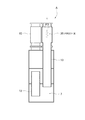
図1は(A)は本考案の一実施形態に係わる消音器Aの正面図、(B)は(A)のB−B線断面図である。
同図に示す本考案の消音器Aは、基本的には三つの部材、すなわち、消音器本体1と入側減圧室10と出側減圧室20とから構成されている。
Next, an embodiment of the present invention will be described with reference to the drawings.
1A is a front view of a silencer A according to an embodiment of the present invention, and FIG. 1B is a sectional view taken along line BB of FIG.
The silencer A of the present invention shown in the figure is basically composed of three members, that is, a
前記消音器本体1は、円筒形の匡体2を2枚の隔壁3,4で区画した3室の消音室、すなわち第1消音室5、第2消音室6および第3消音室7を有している。なお、消音室の数は任意であって、2室でもよく4室以上であってもよい。各消音室5、6、7の内壁には公知の吸音材が貼付されている。
The
前記消音器本体1の入側、すなわち第1消音室5には入側減圧室10が接続管14で接続されている。
前記第1消音室5と第2消音室6の間は連通管11で連通するように接続され、第2消音室6と第3消音室7は、連通管12で連通するように接続されている。第3消音室7からは上方に長い連通管13が延びており、接続管15を介して出側減圧室20が接続されている。
An inlet-
The
前記各消音室5〜7は、連通管11〜13の内径よりもはるかに大きい内径を有していることから、いったん導入された排ガスが内部で膨張と反射を繰返し、脈動圧が壁から壁へと反射し往復する間に干渉しあってエネルギーを失っていく。
また、前消音器本体1内の各消音室5〜7の内壁には適宜の吸音材が貼付される。また、各連通管11〜13の外周面にも吸音材が貼付される。この吸音材によっても、排ガスのもつ圧力波が吸収され、消音効果が生じる。
Since each of the
In addition, an appropriate sound absorbing material is affixed to the inner walls of the
図2は入側減圧室10と連通管11〜12の断面を示す消音器Aの断面図である。この入側減圧室10は、内部が空洞になった円筒形筒体であり、入口の内径と出口の内径のいずれよりも大きな内径を有している。この入側減圧室10は、内部の空洞が入口や出口よりも大きいことから、いったん導入された排ガスが内部で膨張し、脈動圧が平滑化される。本考案者の研究によると、脈動圧の圧力の高いところで音が聞こえてくるので、脈動圧を下げることで消音効果が生じることが分っている。
FIG. 2 is a cross-sectional view of the silencer A showing a cross section of the inlet-
図3は連通管12、13と出側減圧室20の断面を示す消音器Aの断面図である。この出側減圧室20は、内部が空洞になった円筒形筒体であり、入口の内径と出口の内径のいずれよりも大きな内径を有している。この出側減圧室20は、内部の空洞が入口や出口よりも大きいことから、いったん導入された排ガスが内部で膨張し、脈動圧が平滑化される。この出側減圧室20でも、排ガスの脈動圧を下げることで消音効果が大きくなる。
FIG. 3 is a cross-sectional view of the silencer A showing a cross section of the
つぎに、本実施形態の消音器Aによる消音作用を説明する。
図2に示すように、圧力差P1で脈動している排ガスが入側減圧室10に入れられると、いったん入側減圧室10に入った排ガスは、ここで膨張し、整流されることによって脈動圧の圧力差P2が小さくなって、その高いピークが下げられる。このようにして高圧部分が除かれることによって、少し消音した状態で、排ガスは接続管14を経て第1消音室5に送られる。第1消音室5から第3消音室7までは通常の消音作用が行われる。すなわち、消音室5〜7と連通管11、12を順に排ガスが送られ、この間に排ガスは膨張と収縮を繰返して、消音していく。そして、図3に示すように、第3消音室7からは連通管13を通って、出側減圧室20に排ガスが送り込まれる。この出側減圧室20では、再度排ガスが膨張し整流されて脈動圧の高いピークが下げられ小さい圧力差P3となる。このようにして高圧部分が除かれることによって、最終的に消音していく。このように、消音器本体1での本来の消音の前後において、入側減圧室10で事前に減圧し、出側減圧室20で事後に減圧することで、本考案では消音効果が極めて高くなる。換言すれば、同じ消音効果を発揮するなら、消音器全体の寸法を小さくすることができる。
Next, the silencing action by the silencer A of the present embodiment will be described.
As shown in FIG. 2, when the exhaust gas pulsating due to the pressure difference P1 is put into the inlet-
図4は本考案の消音器Aと従来の消音器を対比して示す説明図である。
350kwのガスエンジンから排出される620℃の温度の排ガスを65dBに消音するのに、従来装置では直径dが960mm、高さが約3100mm必要であったところ、本考案の消音器Aは、直径Dが900mm、高さHが約2800mmとなり、高さでは約300mm低くなり、装置表面積は約11m2から約8.5m2に小さくすることができた。このように、本考案では、同じ消音効果を発揮させるのに消音器を相当小型化することができる。
FIG. 4 is an explanatory view showing the silencer A of the present invention in comparison with the conventional silencer.
In order to mute the exhaust gas at a temperature of 620 ° C. discharged from a 350 kw gas engine to 65 dB, the conventional device required a diameter d of 960 mm and a height of about 3100 mm. D was 900 mm, height H was about 2800 mm, height was about 300 mm lower, and the device surface area could be reduced from about 11 m 2 to about 8.5 m 2 . Thus, in the present invention, the silencer can be considerably reduced in size in order to exhibit the same silencing effect.
1 消音器本体
2 匡体
3、4 隔壁
5 第1消音室
6 第2消音室
7 第3消音室
10 入側減圧室
20 出側減圧室
DESCRIPTION OF
Claims (2)
前記消音器本体の入側に接続された入側減圧室と
からなる消音器。 A silencer body having a plurality of silencer chambers;
A silencer comprising an entry-side decompression chamber connected to the entry side of the silencer body.
ことを特徴とする請求項1記載の消音器。 The silencer according to claim 1, further comprising an exit-side decompression chamber connected to an exit side of the silencer body.
Priority Applications (1)
| Application Number | Priority Date | Filing Date | Title |
|---|---|---|---|
| JP2008003548U JP3143896U (en) | 2008-05-29 | 2008-05-29 | Silencer |
Applications Claiming Priority (1)
| Application Number | Priority Date | Filing Date | Title |
|---|---|---|---|
| JP2008003548U JP3143896U (en) | 2008-05-29 | 2008-05-29 | Silencer |
Publications (1)
| Publication Number | Publication Date |
|---|---|
| JP3143896U true JP3143896U (en) | 2008-08-07 |
Family
ID=43293791
Family Applications (1)
| Application Number | Title | Priority Date | Filing Date |
|---|---|---|---|
| JP2008003548U Expired - Lifetime JP3143896U (en) | 2008-05-29 | 2008-05-29 | Silencer |
Country Status (1)
| Country | Link |
|---|---|
| JP (1) | JP3143896U (en) |
-
2008
- 2008-05-29 JP JP2008003548U patent/JP3143896U/en not_active Expired - Lifetime
Similar Documents
| Publication | Publication Date | Title |
|---|---|---|
| JP4392592B2 (en) | Exhaust silencer | |
| CN102235205B (en) | Duct sound damper for flow machine | |
| JP2006300070A (en) | A silencer configured and intended for compressors | |
| CN1312425C (en) | Expansion type silencer, refrigeration cycle circuit using same and manufacturing method thereof | |
| EP2354482B1 (en) | Exhaust muffler device | |
| DK2182186T3 (en) | Silencer for gas flow | |
| CN104832247B (en) | Exhaust silencer for screw-type unit | |
| CN204677259U (en) | A kind of exhaust silencer for screw type unit | |
| CN107587959B (en) | Turbocharger | |
| JP3143896U (en) | Silencer | |
| WO2008014659A1 (en) | A pulse muffler for an air conditioner | |
| RU19555U1 (en) | NOISE MUFFLER | |
| KR101091938B1 (en) | Muffler for Engine Waste Gas with Reduction Means for Jet Noise | |
| JP2006207378A (en) | Noise reduction device for exhaust system and exhaust system having the same | |
| JP2005009483A (en) | Perforated panel noise reduction structure | |
| JPH0637514U (en) | Silencer | |
| CN114576167B (en) | A compressor body | |
| CN116464853A (en) | Muffling Air Pressure Mitigation System | |
| KR19990015920A (en) | Muffler structure of the car | |
| KR100347305B1 (en) | Expention Chamber Silencer with extended inlet and outlet for Deasel generator | |
| JP4324142B2 (en) | Scarf | |
| CN217685828U (en) | Silencer and air conditioner with same | |
| RU171331U1 (en) | REACTIVE NOISE SILENCER | |
| RU2298675C1 (en) | Noise silencer | |
| JP3331806B2 (en) | Silencer |
Legal Events
| Date | Code | Title | Description |
|---|---|---|---|
| R150 | Certificate of patent or registration of utility model |
Free format text: JAPANESE INTERMEDIATE CODE: R150 |
|
| FPAY | Renewal fee payment (event date is renewal date of database) |
Free format text: PAYMENT UNTIL: 20110716 Year of fee payment: 3 |
|
| EXPY | Cancellation because of completion of term |